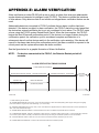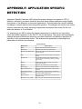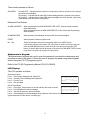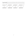
1
FireSeeker
Fire Alarm Control Panel
Model FS-250
Installation, Operation and Maintenance Manual
P/N 315-049353-6 (10.12.05) 8th Edition
Siemens Building Technologies
Fire Safety
TABLE OF CONTENTS
INTRODUCTION ....................................................................................................................................................... 1
CONTROL PANEL LIMITATIONS .....................................................................................................................................1
PREFACE...............................................................................................................................................................................2
DESCRIPTIONS........................................................................................................................................................ 3
FS-250 SYSTEM DESCRIPTION .........................................................................................................................................3
Power Supply .......................................................................................................................................................................3
P2 Addressable Device Circuit............................................................................................................................................3
Notification Appliance Circuits ...........................................................................................................................................4
Serial Interface Circuit ........................................................................................................................................................4
Status Relays........................................................................................................................................................................4
Programming Port...............................................................................................................................................................4
OPTIONAL MODULES ........................................................................................................................................................5
FS-MT Municipal Tie Board................................................................................................................................................5
FS-DACT Board ..................................................................................................................................................................5
FS-NPE Transformer Assembly...........................................................................................................................................5
FS-DLC Loop Driver Board ................................................................................................................................................5
Battery Sets ..........................................................................................................................................................................5
FS-REL Releasing Module...................................................................................................................................................5
AUXILIARY MODULES ......................................................................................................................................................6
Serial LCD Annunciator ......................................................................................................................................................6
Serial Relay Unit and Serial Relay Extender.......................................................................................................................6
Serial Annunciator Unit and Serial Annunciator Extender .................................................................................................6
PAD-3 Remote Signal Expander..........................................................................................................................................6
P2 ADDRESSABLE DEVICES .............................................................................................................................................7
FirePrint™ Smoke Detector ................................................................................................................................................7
Heat Detectors .....................................................................................................................................................................7
Addressable Modules (Monitor and Control) ......................................................................................................................7
Manual Stations ...................................................................................................................................................................7
Programming P2 Devices ....................................................................................................................................................7
EVENT HISTORY .................................................................................................................................................................9
GENERAL DESIGN FEATURES .........................................................................................................................................9
Environmental......................................................................................................................................................................9
Power Limiting ....................................................................................................................................................................9
Ground Fault Detection.......................................................................................................................................................9
NAC Operation ....................................................................................................................................................................9
Transient Protection ............................................................................................................................................................9
Security Features .................................................................................................................................................................9
REGULATORY STANDARDS...........................................................................................................................................10
Federal Communications Commission ..............................................................................................................................10
Underwriters Laboratories ................................................................................................................................................10
GENERAL SPECIFICATIONS ...........................................................................................................................................11
Environmental....................................................................................................................................................................11
Primary Supply ..................................................................................................................................................................11
Secondary and Trouble Power Supply...............................................................................................................................11
Auxiliary Power Outputs ...................................................................................................................................................11
Status Relays......................................................................................................................................................................11
Notification Appliance Circuits .........................................................................................................................................12
Serial Interface Circuit ......................................................................................................................................................12
P2 Addressable Device Circuits ........................................................................................................................................12
Municipal Tie (Optional Municipal Tie Board FS-MT).....................................................................................................13
DACT Circuit (Optional DACT Board FS-DACT) ............................................................................................................13
Additional Transformer (Optional Transformer Sub-Assembly FS-NPE) .........................................................................13
FS-REL (Optional Releasing Module)...............................................................................................................................13
i
CONTROL PANEL OPERATION ........................................................................................................................... 14
OPERATION INSTRUCTIONS ..........................................................................................................................................14
Standby Condition..............................................................................................................................................................14
Alarm Conditions...............................................................................................................................................................14
Trouble Conditions ............................................................................................................................................................16
Supervisory Conditions......................................................................................................................................................17
Pre-Alarm Conditions........................................................................................................................................................17
Maintenance ......................................................................................................................................................................17
ADDITIONAL OPERATING PROCEDURES ...................................................................................................................18
Lamp Test...........................................................................................................................................................................18
Drill ...................................................................................................................................................................................18
Recall .................................................................................................................................................................................18
Alert ...................................................................................................................................................................................18
History ...............................................................................................................................................................................19
FS-250 OPERATING INSTRUCTIONS..............................................................................................................................20
Alarm Operation................................................................................................................................................................20
Authorized Personnel Only ................................................................................................................................................20
Trouble Operation .............................................................................................................................................................20
Normal Standby Condition ................................................................................................................................................20
FS-RD2 OPERATING INSTRUCTIONS ............................................................................................................................21
Alarm Operation................................................................................................................................................................21
Authorized Personnel Only ................................................................................................................................................21
Trouble Operation .............................................................................................................................................................21
Normal Standby Condition ................................................................................................................................................21
FS-250 with RELEASING OPERATING INSTRUCTIONS ..............................................................................................22
Pre-Alarm Operation.........................................................................................................................................................22
Alarm Operation................................................................................................................................................................22
Authorized Personnel Only ................................................................................................................................................22
Trouble Operation .............................................................................................................................................................22
Normal Standby Condition ................................................................................................................................................22
CONTROL PANEL INSTALLATION ...................................................................................................................... 27
Enclosure Packages (Black or Red)...................................................................................................................................23
FS-250 Electronics Package..............................................................................................................................................23
FS-250 Electronics Package2............................................................................................................................................23
With FS-NPE Transformer Package..................................................................................................................................23
CAUTIONS ..........................................................................................................................................................................24
CONTROL PANEL LOCATION.........................................................................................................................................24
INSTALLATION .................................................................................................................................................................24
ENCLOSURE MOUNTING ................................................................................................................................................24
FS-250 Enclosure Mounting Pictures................................................................................................................................25
Remove Knock-Outs...........................................................................................................................................................26
Main Board Installation – FS-MB / FS-MB2.....................................................................................................................26
Bridge Rectifier Installation ..............................................................................................................................................27
FS-NPE Transformers Mounting.......................................................................................................................................28
FS-DLC Loop Driver Board Mounting..............................................................................................................................29
FS-DB / FS-DB2 Display Board Installation.....................................................................................................................30
SYSTEM WIRING.................................................................................................................................................... 31
AC Supply Connection .......................................................................................................................................................31
Battery Installation ............................................................................................................................................................32
Powering the Control Panel ..............................................................................................................................................32
Optional Modules ..............................................................................................................................................................32
Check System Operation....................................................................................................................................................32
WIRING................................................................................................................................................................................32
Control Panel Wiring Overview ........................................................................................................................................33
Wiring Entering Enclosure ................................................................................................................................................33
Install Wiring .....................................................................................................................................................................33
Wiring Separation..............................................................................................................................................................34
ii
Primary And Secondary Power Wiring .............................................................................................................................35
Status Relays And Auxiliary Power Outputs Wiring..........................................................................................................35
FS-250 System Power Requirements (Does not include NAC power) ...............................................................................36
Auxiliary Power Supply .....................................................................................................................................................36
Battery Size Calculations...................................................................................................................................................36
NAC Wiring .......................................................................................................................................................................37
Releasing Zone Wiring (Use only if FS-REL is installed)..................................................................................................38
Compatible Solenoids ........................................................................................................................................................38
Serial Interface Circuit ......................................................................................................................................................39
Serial Remote Device Wiring Overview.............................................................................................................................40
P2 Addressable Device Circuit..........................................................................................................................................41
P2 Addressable Device Wiring Diagrams .........................................................................................................................42
PROGRAMMING THE CONTROL PANEL ............................................................................................................ 44
KEYPAD PROGRAMMING ...............................................................................................................................................44
PC PROGRAMMING ..........................................................................................................................................................44
PROGRAMMING SECURITY............................................................................................................................................44
MAINTENANCE ...................................................................................................................................................... 45
GENERAL............................................................................................................................................................................45
QUICK TEST .......................................................................................................................................................................46
APPENDIX-A: REFERENCE DATA ....................................................................................................................... 47
WIRE SELECTION GUIDES ..............................................................................................................................................47
Resistance of Solid Copper Wire .......................................................................................................................................47
Notification Appliance Circuit Wire Selection Guide ........................................................................................................47
Maximum Wire Loop Distance (Feet)................................................................................................................................47
Addressable Device Circuit Wire Selection Guide ............................................................................................................48
Line Resistance Graph.......................................................................................................................................................48
BATTERY SIZE CALCULATIONS ...................................................................................................................................49
FS-250 Current Calculations.............................................................................................................................................49
Auxiliary Module Battery Calculations .............................................................................................................................50
Device Current Calculations .............................................................................................................................................50
Total System Currents........................................................................................................................................................51
Battery Size ........................................................................................................................................................................51
APPENDIX-B: COMPATIBLE DEVICES................................................................................................................ 52
DEVICES FOR ADDRESSABLE DEVICE CIRCUITS.....................................................................................................52
Siemens P2 Manual Pull Stations ......................................................................................................................................52
Siemens P2 Modules ..........................................................................................................................................................52
Siemens P2 Detectors ........................................................................................................................................................52
Siemens P2 Bases ..............................................................................................................................................................52
Siemens P2 Accessories .....................................................................................................................................................52
DEVICES FOR NOTIFICATION APPLIANCE CIRCUITS ..............................................................................................54
APPENDIX-C: TROUBLESHOOTING.................................................................................................................... 63
DEFINITIONS FOR EVENT HISTORY ENTRIES ...........................................................................................................63
A. General..........................................................................................................................................................................63
B. System Troubles.............................................................................................................................................................64
C. System Events ................................................................................................................................................................65
APPENDIX-D: MODULE INSTALLATION INSTRUCTIONS LIST ........................................................................ 66
APPENDIX-E: ALARM VERIFICATION ................................................................................................................. 67
APPENDIX-F: APPLICATION SPECIFIC DETECTION......................................................................................... 68
APPENDIX-G: TESTING/MAINTENANCE............................................................................................................. 69
APPENDIX-H: LCD, CONTROLS AND INDICATORS .......................................................................................... 70
Communication Port Connector ........................................................................................................................................70
LEDS, Sounder and Dedicated Push Buttons ....................................................................................................................70
Alphanumeric Keypad: ......................................................................................................................................................71
LCD Display:.....................................................................................................................................................................71
APPENDIX-I: GLOSSARY...................................................................................................................................... 73
iii
iv
INTRODUCTION
CONTROL PANEL LIMITATIONS
This control panel may not show an alarm condition without compatible initiating devices
(smoke detectors, etc.) and notification devices (horn, lights, etc.) connected to it. Electrical
ratings of the initiation and notification appliances must be compatible with the electrical ratings
of the control panel and must be properly interconnected. The wiring used for interconnection
must be large enough to carry the total current for all appliances without excessive voltage
drop.
The control panel must be connected to a dedicated primary electrical source that has a high
degree of reliability and adequate capacity for this control panel. The only means of
disconnecting this power source shall be available only to authorized personnel and clearly
marked "Fire Alarm Circuit Control".
The control panel must also have connected to it a battery set (24V) that has enough capacity
to properly operate the system for 24 or 60 (depending on system type) hours standby and 5
minutes alarm per NFPA 72 (Chapter 1). These batteries do lose capacity with age. Batteries
must be replaced when they fail to provide the control panel with the required standby and
alarm power or after 4 years, whichever happens first. These batteries must be checked for
performance at least two (2) times a year or more often if local requirements dictate.
Even though this control panel was made to last for the expected life of the fire alarm system,
any part could fail at any time. Therefore a regular test program should be followed and
documented to make sure that each part of the system is tested as in Chapter 7 of NFPA 72 or
more often if dictated by local code requirements. Malfunctioning units must be replaced or
repaired immediately by factory authorized service personnel.
This control panel is designed to show an alarm condition when the initiating devices
connected to it detect specific conditions. These conditions may or may not represent a lifethreatening condition. Also, evacuation of a building or area unnecessarily may subject
individuals to an unnecessary hazard. Therefore, it is most important that the building owner,
manager, or representative promulgate, distribute, and/or post instructions describing steps
to be taken when the fire alarm control panel signals an alarm condition. These instructions
should be developed in cooperation and conformance with representatives of the local
authority having jurisdiction.
As a backup or precautionary measure, it is strongly suggested that one of these steps should
be to notify the local fire department of an abnormal condition even where the DACT option (or
similar device) is included in the system.
1
PREFACE
Along with the use of this instruction manual, the appropriate following standards and the
manufacturer's instructions for initiating and notification devices should be used to install and
maintain a functioning fire alarm signaling system.
NFPA 70 National Electrical Code
NFPA 72 National Fire Alarm Code
NFPA 101 Life Safety Code
For other standards that may apply contact the authority having jurisdiction.
In order to comply with NFPA 12A, NFPA 13 and NFPA 2001, the FS-REL releasing module
must be installed.
For NFPA publications, contact:
National Fire Protection Association
Batterymarch Park
Quincy, Massachusetts 02269
2
GENERAL DESIGN FEATURES
Environmental
The FS-250 panels and its subassemblies are suitable for use in a dry, interior or protected
location.
Power Limiting
The AC power and battery wiring are not power limited. All other circuits leaving the control
panel are power limited, provided the proper installation rules are maintained.
Ground Fault Detection
The control panel provides system ground fault detection and is annunciated as a trouble
condition on the system. In addition, each addressable loop circuit has its own ground
detection circuitry and indicator.
NAC Operation
The notification appliance circuits are commanded and controlled by a mircroprocessor to
provide more versatility than in a total hardware system.
•
Output Sounding Patterns - The notification appliance circuits are operable in different
sounding patterns. Any circuit is selectable to any of eight software-generated patterns or
continuous sounding. For convenience, three of the patterns are preprogrammed for March
Time, Temporal, and Siemens SYNC Protocol.
•
Audible Silence Inhibit - In addition to designation of water flow zones, the entire control
panel may be programmed to inhibit audible silence for 0, 1, 3, or 6 minutes from the last
alarm. System reset may also be inhibited.
Transient Protection
Transient protection devices are provided to meet UL864 requirements.
Security Features
Processor control and addressing allow inclusion of several functions to assure security and
proper programming of the system.
Multi-level password protection of programming functions prevents unauthorized configuration
changes.
Device type supervision: If the type reported by an addressable detector or module does not
agree with the configuration, the system reports a trouble.
Device address supervision: The system checks that all configured devices on the addressable
device circuit and the Serial Interface Circuit responds to an address poll. If a configured
device is missing, the system reports a trouble. The system also polls unused addresses
periodically. If a device responds to such a poll of a non-configured device, the system reports
a trouble. Two devices addressed the same also cause a trouble to be reported.
9
REGULATORY STANDARDS
The FS-250 control panel meets the requirements of industry and government regulatory
agencies as noted.
Federal Communications Commission
The FS-DACT meets the Class A requirements of the Code of Federal Regulations (CFR 47),
Part 15 for electromagnetic field emissions. The FS-DACT also meets the requirements of the
Code of Federal Regulations (CFR 47), Part 68, for connection of equipment to the public
switched telephone network.
Underwriters Laboratories
The FS-250 Fire Alarm control panel is listed under UL Standard 864 for compliance to NFPA
Standard 72 for fire service.
10
CONTROL PANEL OPERATION
OPERATION INSTRUCTIONS
Standby Condition
In normal standby operation, the green AC POWER ON LED should be illuminated and no
other indicator operating. The display will show the system name, “System Normal”
announcement and the current date, day, and time.
Alarm Conditions
• GENERAL ALARM
• When a general alarm occurs, all NACs with output type set to “ALARM” activate. To
activate a general alarm, proceed as follows:
• - Press “MENU”.
• - On the Menu display, select “GENERAL ALARM”.
• At the next screen, select “Yes”.
• Silence and reset the system as with any alarm.
• NORMAL ALARM
In case of alarm, the system alarm LED activates (ON – flashing) and the buzzer activates (ON
– steady). Local audible and visual signals and remote alarm signals operate, and the LCD
panel display indicates the zone or point initiating the alarm.
On receipt of an alarm, proceed in accordance with the established emergency plan. Assure
that all personnel are accounted for, and notify the Fire Department.
To silence the audible after evacuation, where permitted by the codes and control panel
programming, press ALARM SILENCE. The alarm audible will be silenced, the alarm silence
LED will be illuminated and a system trouble indicated.
Operating the ACKNOWLEDGE button will silence the local buzzer and change the LED alarm
indicator from flashing to steady.
• WATERFLOW Alarms
Alarms detected on devices with usage designated as “waterflow” indicate sprinkler operation
and the audible alarms cannot be silenced in this condition. Operation of alarm silence will
produce no effect.
• POSITIVE Alarm Sequence (PAS)
Activation of an initiating device in an input group programmed for PAS, activates the Alarm
LED, display, buzzer, system and user-programmed outputs, but delays additional
programmed outputs for 15 seconds.
Operation of the ACKNOWLEDGE button within 15 seconds will add a number of seconds (60180) to the PAS timer for the purpose of investigation. If the ACKNOWLEDGE button is not
operated within 15 seconds, the additional user-programmed outputs activate.
14
If the initiating device and the panel are reset before the PAS timer times out, the alarm
sequence is aborted.
During the investigation period, an alarm condition on a detector programmed for direct alarm
response (such as the key switch on a manual station) will override the PAS timer and activate
the additional user-programmed outputs.
See the FS-250 Programming Manual, P/N 315-049403, for additional details.
• PRE-SIGNAL ALARMS
Activation of an initiating device in an input group programmed for PRE_SIGNAL, activates the
Alarm LED< display, buzzer, system and user-programmed outputs.
The delay of activation of additional user-programmed outputs can be programmed from 60 to
180 seconds. If the system is not reset during this periond, these additional user-programmed
outputs will activate.
See the FS-250 Programming Manual, P/N 315-049403, for additional details.
Do not reset the system until the alarm condition has been cleared. The LCD display will
indicate the area in which the alarm was detected. The detector or module associated with the
device initiating the alarm will display a light indicating activation (if applicable).
When the alarm condition has been corrected, return the system to standby operation by
pressing the SYSTEM RESET button.
• ALARMS ON RELEASING ZONES
Devices that will activate the releasing circuits must be assigned to the releasing group via the
FS-CT2 configuration tool or front panel programming. The releasing group may be configured
to activate on any one alarm, a number of alarms (between 2 – 10) or any one smoke plus any
one thermal alarm.
For instance, if the threshold of the group was set at any 2, the following would occur: The first
device activating will put the panel in a releasing group pre-alarm condition. When the second
device in that zone activates, it will start the agent release timer and put the panel in predischarge condition. If the threshold were to be set at one, any device in that group activating
would immediately start the agent release timer.
When the agent release timer is activated, the LCD display will display the timer as it counts
down. The screen will display “agent release in XX seconds” and the “Pre-Discharge” LED will
be ON-steady.
When the agent release timer expires, the panel goes to the discharge condition and activates
the releasing zone. This is indicated by the “Discharge” LED turning ON-steady.
15
Abort Function
Input modules may be assigned to the “Abort” function. The abort type is selected when
programming the releasing group. Failure of the abort switch to communicate with the fire panel will
automatically restart the agent release timer. When the abort input is activated, it puts the panel in
abort condition and turns the “Abort” LED to steady-ON. The following abort functions may be
assigned:
ULI Standard UL Type Delay Timer
If a monitor module is programmed for ULI, when it is activated the abort indicator will indicate
and the timer will continue to count down until it reaches 10 seconds. At that point, the timer
will stop as long as the abort switch is active. When the abort switch clears, the timer will
restart at 10 seconds.
IRI Type Delay Timer
The IRI type delay timer functions identical to the ULI timer except that the Abort timer will only
function if it is activated and held before the second activation of a cross zone.
NYC Type Delay Timer
If a module is programmed for NYC, when it is activated it will change to the timer value plus 90
seconds. The timer will not start as long as the abort switch is held.
AHJ Local Jurisdiction Delay Timer
Once the timer is started, activating this module will restore the timer to its full time. The timer will
not start as long as abort is held. Releasing the abort switch will start the timer. Re-activating it will
restore it to its full time.
Manual Release
Input modules will also have an input usage “Manual Release”. If an input module programmed for
Manual Release is activated, it will override all abort timers and automatically activate the releasing
circuit, putting the panel in discharge condition.
Trouble Conditions
In case of a trouble condition, the system trouble LED and any programmed trouble LEDs
activate (ON – pulsing), the LCD display identifies the problem, and the buzzer sounds
(pulsing). Refer to the applicable section of the system manual to determine the probable
cause of the trouble and the action to be taken.
When a trouble has been noted, the buzzer may be silenced by pressing the ACKNOWLEDGE
button. The trouble LEDs will change to ON - steady. If the trouble has not been corrected
when the trouble resound reminder expires, the trouble display reverts to its original condition
and the buzzer resounds (pulsing).
If the control panel is programmed for “trouble acknowledge required”, when the indicated
trouble condition has been cleared, the system reverts to standby condition only after the
ACKNOWLEDGE button is pressed.
Some trouble conditions are latching troubles that require a system reset to restore the
control panel to supervisory mode.
16
Supervisory Conditions
In case of a supervisory condition, the system supervisory LED activates (ON – flashing) and
the sounder activates (ON – pulsing). When the supervisory has been listed, the buzzer is
silenced by pressing the “ACKNOWLEDGE” button. The supervisory trouble LED changes to
ON –steady. When the supervisory is cleared, the supervisory condition is still indicated until it
is acknowledged. The releasing zone will indicate a supervisory condition when it is disabled.
Pre-Alarm Conditions
• A pre-alarm condition is annunciated by Pre-alarm LEDs and buzzers on the control panel
and LCD Annunciators and Remote Processors. The LEDs flash and buzzers are on
steady until acknowledgment.
• Acknowledging the Pre-alarm condition puts LEDs on steady and buzzers off.
• If pre-alarm has been acknowledged and the system restores to normal, the condition
clears. If the system proceeds into an alarm condition, the pre-alarm condition clears
whether or not it has been acknowledged and is replaced by alarm.
Maintenance
In order to insure continued safe and reliable operation of the fire alarm system, periodic
inspection and testing should be performed in accordance with applicable NFPA 72 standards.
If the system has remote connections to the Fire Department or other monitor, be sure to
disable the remote signals and/or notify the remote monitoring station before performing test
operations.
For any required service, refer to the system manual or contact a factory authorized
representative.
To access the Panel Firmware Version Number:
•
•
•
•
Press “MENU” on the Keypad.
Select the “Maintenance” mode.
Enter the maintenance password.
If the password is correct, the firmware version will be shown on the LCD screen.
17
ADDITIONAL OPERATING PROCEDURES
In addition to the basic fire alarm instructions above, several features are included to facilitate
maintenance and increase the versatility of the system. Following are procedures to call up
these functions.
Lamp Test
Lamp Test activates the buzzer and turns on all the LEDs on the user interface for 2 seconds,
then reverts to its previous state.
To operate the lamp test, press the MENU button. The LCD display will change to a MENU
screen. Press the button next to the “More” indication twice. Then press the button by the “Lamp
Test” indication. All lamps on the unit being operated will then light. Operating the button next to
“Esc” will then return the control panel to normal display. Note that the lamp test operates the
indicators only on the unit being operated, and no record is reported to system history.
Drill
When selected, activates all NACs assigned to the Output Zone selected for “Drill”.
To activate a fire alarm drill, proceed as follows:
•
•
•
•
•
Press "MENU".
On the MENU display, select "More".
At the next screen, select "DRILL".
At the next screen, select "Yes".
Operate ALARM SILENCE to terminate drill signal.
Recall
When selected, activates all NACs assigned to Output Ones selected for “Recall”.
To signal recall after a drill, proceed as follows:
•
•
•
•
•
Press "MENU".
At the next screen, select "More".
Select "RECALL".
At the next screen, select "Yes".
Operate ALARM SILENCE to terminate recall signal.
Alert
To activate alert alarm, proceed as follows:
•
•
•
•
Press "MENU".
On the MENU display, select "ALERT".
At the next screen, select "Yes".
Operate ALARM SILENCE to terminate alert signal.
18
History
The last 2000 system events are time-tagged and recorded for review in the user level event
history. This history is available to anyone with the door key, but may be erased only at the
maintenance security level.
•
Operation of history:
New events overwrite old when filled.
Printer (if used) records all events.
For more information see the event history section.
•
Access to history:
To recall past events, proceed as follows:
Press “MENU” button.
Operate button identified as "More".
Operate button identified as "More".
Operate button identified as "View History".
Operate upper left button (M1) for previous event display.
Operate lower left button (M2) for next event display.
Operate upper right button (M3) to exit to MENU DISPLAY.
The display reverts to its previous state if there is no action performed within 30 seconds.
19
FS-250 OPERATING INSTRUCTIONS
Alarm Operation
In case of alarm, the Alarm LED flashes, LCD displays alarm condition and the panel buzzer sounds
steady. Local audible and visual signals and remote alarm signals operate.
When an alarm occurs, proceed according to the established emergency plan. Assure that all personnel
are accounted for, and notify the Fire Department to advise of the alarm and/or verify that an automatic
signal has been received at the Fire Department.
Authorized Personnel Only
To acknowledge the alarm:
To acknowledge the alarm, press the Acknowledge button. The local buzzer will be silenced and
the Alarm LED will change from on-flashing to on-steady.
To silence the alarm:
To silence the notification appliances after evacuation, where permitted, press the Alarm Silenced
button. The silenceable notification appliances will be silenced. The Alarm Silenced LED will be
on-steady.
Note: Do not reset the panel until the alarm has been cleared.
Warning: Alarm silence inhibit (if set) prevents the alarm from being silenced for a
predetermined time.
To reset panel after alarm:
When the alarm condition is corrected, return the panel to normal standby operation by pressing
the System Reset switch.
Trouble Operation
Trouble is indicated by:
Trouble LED flashes
LCD will display trouble conditions
Panel buzzer sounds on-pulsing
To acknowledge the trouble buzzer:
Press the Acknowledge button. The Trouble LED turns on-steady and the buzzer turns off. When
the trouble condition has been cleared, you may need to reset the panel to restore to a normal
standby condition.
Warning: Leaving the panel in a trouble condition may cause a fire alarm condition not to
initiate a fire alarm sequence.
Normal Standby Condition
The green AC Power On LED will be lit and no other indicators on.
For service, contact: ___________________________________________
Telephone Number: _____________________________________________
Frame these instructions and mount them near the control panel for operator reference.
20
FS-RD2 OPERATING INSTRUCTIONS
Alarm Operation
In case of alarm, the Alarm LED flashes, LCD displays alarm condition and the buzzer activates
on-steady. Local audible and visual signals and remote alarm signals operate.
When an alarm occurs, proceed according to the established emergency plan. Assure that all personnel
are accounted for, and notify the Fire Department to advise of the alarm and/or verify that an automatic
signal has been received at the Fire Department.
Authorized Personnel Only
To acknowledge the alarm:
To acknowledge the alarm, press the Acknowledge button. The local buzzer will be silenced and
the Alarm LED will change from on-flashing to on-steady.
To silence the alarm:
To silence the notification appliances after evacuation, where permitted, operate the Button
Enable key switch and press the Alarm Silence switch. The notification appliances will be
silenced. The Alarm Silenced LED will be on-steady.
Note: Do not reset the panel until the alarm has been cleared.
Warning: Alarm silence inhibit (if set) prevents the alarm from being silenced for a
predetermined time.
To reset panel after alarm:
When the alarm condition is corrected, return the panel to normal standby operation by placing
the Button Enable key switch in the OK position and then pressing the System Reset switch.
Trouble Operation
Trouble is indicated by:
Trouble LED flashes
LCD will display trouble conditions
Buzzer activates on-pulsing
To silence the trouble buzzer:
Operate the Button Enable key switch to the ON position and press the Acknowledge button. The
Trouble LED changes to on-steady. When the trouble condition has been cleared, you may need
to reset the panel to restore to a normal standby condition.
Warning: Leaving the panel in a trouble condition may cause a fire alarm condition not to
initiate a fire alarm sequence
Normal Standby Condition
The green Power On LED will be lit and no other indicators on.
For service, contact: ___________________________________________
Telephone Number: _____________________________________________
Frame these instructions and mount them near the annunciator for operator reference.
21
FS-250 WITH RELEASING OPERATING INSTRUCTIONS
Pre-Alarm Operation
In case of an alarm on one of the devices on a releasing zone, the Pre-Alarm LED flashes, the LCD displays prealarm condition, the buzzer activates on-steady and any NACs configured to sound Pre-alarm will sound.
Alarm Operation
When another alarm occurs and the set threshold is satisfied on a releasing zone, the agent release timer is
activated. The LCD display will display the timer as it counts down. The screen will display “agent release in XX
seconds” and the “Pre-Discharge” LED will be on. Proceed according to the established emergency plan. Assure that
all personnel are accounted for and notify the Fire Department to advise of the alarm and/or verify that an automatic
signal has been received at the Fire Department.
Authorized Personnel Only
To Abort the suppression release
Press the Abort switch, depending on the configuration of the panel the pre discharge timer will be halted or
reset. Proceed to clearing and acknowledging the alarm.
To acknowledge the alarm:
To acknowledge the alarm, press the Acknowledge button. The local buzzer will be silenced and the Alarm
LED will change from on-flashing to on-steady.
To silence the alarm:
To silence the notification appliances after evacuation, press the Alarm Silence switch. The notification
appliances will be silenced. The Alarm Silenced LED will be on-steady.
Note: Do not reset the panel until the alarm has been cleared.
Warning: Alarm silence inhibit (if set) prevents the alarm from being silenced for a predetermined
time.
To reset panel after alarm:
When the alarm condition is corrected, return the panel to normal standby operation by pressing the System
Reset switch.
To initiate manual release:
Press the Manual Release switch. This will immediately activate the releasing zone and put the panel to
discharge condition regardless of the previous condition of the panel.
NOTE: Manual release and abort switch are installed external to the panel and normally monitored
by contact devices.
Trouble Operation
Trouble is indicated by:
Trouble LED flashes
LCD will display trouble conditions
Buzzer activates on-pulsing
To silence the trouble buzzer:
Operate the Button Enable key switch to the ON position and press the Acknowledge button. The Trouble
LED changes to on-steady. When the trouble condition has been cleared, you may need to reset the panel
to restore to a normal standby condition.
Warning: Leaving the panel in a trouble condition may cause a fire alarm condition not to initiate a
fire alarm sequence
Normal Standby Condition
The green Power On LED will be lit and no other indicators on.
For service, contact: ___________________________________________
Telephone Number: _____________________________________________
Frame these instructions and mount them near the annunciator for operator reference.
22
MAINTENANCE
GENERAL
The FS-250 provides a maintenance mode to allow for the setting and controlling of various
features in the system.
The maintenance functions are protected by a four digit password. To access the maintenance
features press the “MENU” button four times and select “Maint. Level” from the display, enter
the four digit code when prompted and then press “Enter”. The functions listed below are now
accessible to the user by using the function buttons on either side of the display.
Disable/Enable Devices
Disable/ Enable Groups
Disable Zones
Disable NACs
Disable City Tie
Disable DACT
Disable Status Relays
Disable/Enable Detector Applications
Quick Test
Print History
Print Sensor Levels
Edit Device Labels
Edit System Labels
Program a Device
Set the Time
Set the Date
Change the Password
Clear the History
Refer to the programming manual for more information about accessing and using the
maintenance level functions.
45
QUICK TEST
If the control unit has remote connections to the Fire Department or other monitor, be sure to
disable the remote signals and notify the remote monitoring station before performing test
operations, since an off-normal condition will be indicated.
The Quick Test mode makes it fast and easy to test a system by eliminating the need to reset
the panel after each device is activated. Quick test is done on a loop basis so that the
remainder of the system will continue to operate normally. Once the loop is placed into quick
test, the NACs will sound for a short configurable period as each device on the loop is
activated. In this way a single person is able to quickly check that each device is working and
activating the system.
The printer may also be enabled or disabled during “Quick Test” as desired.
Refer to the programming manual for the details of accessing the Quick test functions.
For any required service, contact a factory-authorized representative.
46
APPENDIX-C: TROUBLESHOOTING
DEFINITIONS FOR EVENT HISTORY ENTRIES
A. General
ENTRY
ALARM
ALRM
AVCntr
Blank
CrossZone
CZ1A
CZ1B
CZ2A
CZ2B
DETECTOR
HEAT
ION
LCDxx
MAIN
MANL PULL
Mntc
PAS
PAS INHBT
PHOTO
PRE SIGNL
PreA
SUPERVSRY
SUPR
TRBL
TROUBLE
USERx
WATERFLOW
INDICATES
General alarm
Alarm
Alarm Verify counter
Plain alarm
cross zone point
Cross zone
Cross zone
Cross zone
Cross zone
General alarm
Thermal detector
Ion detector
LCD Annunciator xx
Main panel
Manual pull station
Detector maintenance alert
Positive alarm sequence
PAS inhibit switch
PE detector
pre-signal
Pre-alarm
Supervisory
Supervisory
Trouble
Trouble
User-defined input x
Waterflow
63
B. System Troubles
ENTRY
AC Trouble
AddrLp 1 DBLSHT
AddrLp 1 OPEN
AddrLp 1 SHORT
BATT Trouble
CITY Trouble
DACT Acct Trb
DACT Com Trouble
DACT PL x Trouble
FLASH FATAL Trb
GRND FAULT Trbl
LCDxx NoRespons
LCDxx Not Pgmd
LCDxx Trouble
MNLP Bad Msg
MNLP Fifo Xmit
MNLP NoRespons
NACxx Trouble
PC Pgmr Trb
QuickTest Abort
Trb Reminder
INDICATES
AC input low or off
Double short trouble on addressable loop 1
Open circuit trouble on addressable loop 1
Short circuit trouble on addressable loop 1
Battery input low or off
Local Energy circuit open
DACT account reporting trouble
DACT communication trouble with main processor
Open or short on DACT phone line x
Configuration Flash memory trouble
Ground Fault trouble
LCD Annunciator xx programmed but is not responding
LCD Annunciator xx is not programmed but is responding
LCD Annunciator xx reports trouble
Main processor to loop processor communication trouble
Main processor to loop processor communication trouble
Main processor to loop processor communication trouble
NAC xx wiring is open or shorted
Control panel is not receiving communication from PC
Quick Test Timer expired causing abnormal exit of Quick Test
Trouble Reminder timer expired
64
C. System Events
ENTRY
Alarm Silenced
All AV Ctrs Clr
AutoProgram Run
Backup Cnfg Check
Backup Cnfg Edit
ConfigsCompared
ConfigsSwapped
EventHist Clear
Mnt Levl Enter
Mnt Levl Exit
Mnt Levl PW Changed
NACxx Active Confirm
Panel Reset
Power Up
PriConfigCopied
QuickTest Exit
QuickTest Start
System Date Changed
System Time Changed
Tech Levl Enter
Tech Levl Exit
Tech Levl PW Changed
User Levl Enter
User Levl Exit
INDICATES/NOTES
MAIN, LCDxx shown on bottom line
All AV counters cleared
Auto programming function run
Backup configuration validated, result on bottom line
Backup configuration edited
Backup and primary configurations compared, result on bottom line
Backup and Primary configurations swapped
Event History cleared
Entered Maintenance level
Exited Maintenance level
Changed Maintenance level password
NAC activation confirmed
MAIN, LCDxx shown on bottom line
Primary configuration copied to backup
Exited Quick Test, MAIN or LCDxx shown on bottom line
Started Quick Test, MAIN or LCDxx shown on bottom line
Changed system date, old and new dates shown on lines 3 and 4
Changed system time, old and new times shown on lines 3 and 4
Entered Tech level
Exited Tech level
Changed Tech level password
Entered User level
Exited User level
65
APPENDIX-E: ALARM VERIFICATION
Alarm verification provides FS-250 with a way to verify an alarm from area type addressable
smoke detectors connected to intelligent loops (FS-DLC). This feature reduces the incidence
of false alarms. Only detectors that do not contain an integral alarm verification feature can be
used.
Addressable detectors connected to FS-DLCs indicate that an alarm condition has been
detected. If the device is subject to alarm verification, the FS-DLC alerts the control panel that
the device has entered verification but is not yet considered to be in alarm. The FS-DLC starts
a timer using the FS-250 system Retard-Reset Period. When the timer expires, the FS-DLC
begins the fixed 60-second confirmation period. If the device is no longer in alarm during the
confirmation period, the verification cycle is considered complete and detection of a
subsequent alarm from that device results in the verification cycle restarting. If the device still
reports in the alarm state during this confirmation period, the alarm condition is reported to the
control panel and the system annunciates the alarm condition.
See the figure below for a graphic illustration of Alarm Verification.
NOTE:
For devices connected to the FS-DLC, the Detector Restart period is 0
seconds.
ALARM VERIFICATION TIMING DIAGRAM
ALARM VERIFICATION PERIOD
RETARD-RESET-RESTART PERIOD -- MAXIMUM 60 SECONDS
CONFIRMATION PERIOD -- 60 SECONDS
OPTIONAL
NO ALARM AT CONTROL UNIT
ALARM REQUIRED AT CONTROL UNIT
REGION
CONTROL UNIT
DETECTOR RESTART
RETARD-RESET PERIOD
(POWER-UP) PERIOD
B
A
C
t=0 Seconds
E
D
t=n Seconds
A - Smoke detector goes into alarm.
AB - RETARD-RESET PERIOD (Control Unit) - Control unit senses detector in alarm and retards (delays) alarm signal, usually by de-energizing
power to the detector. Length of time vaires with design. (11 to 55 seconds)
BC - RESTART PERIOD (Detector Power-up Time) - Power to the detector is reapplied and time is allowed for detector to become operational for
alarm. Time varies with detector design.
AC - RETARD-RESET-RESTART PERIOD - No alarm obtained from control unit. Maximum permissible time is 60 seconds.
CD - CONFIRMATION PERIOD - Detector is operational for alarm at point C. If detector is still in alarm at point C, control unit will alarm. If detector
is not in alarm, system returns to standby. If the detector re-alarms at any time during the confirmation period the control unit will alarm.
DE - OPTIONAL REGION - Either an alarm can occur at control unit or restart of the alarm verification cycle can occur.
AD - ALARM VERIFICATION PERIOD - Consists of the retard-reset-restart and confirmation periods.
67
APPENDIX-F: APPLICATION SPECIFIC
DETECTION
Application Specific Detection (ASD) allows the system designer to program an HFP-11
detector’s sensitivity, pre-alarm threshold, and other alarm-related parameters using English
descriptions of the detector's environment (application). This eliminates the need for detailed
knowledge of smoke detector terminology and operation. The designer can set all of the critical
detector parameters by simply selecting an application description that closely fits the one
where the detector is to be installed.
For example, to use ASD to select the optimal parameters for a detector in a hotel lobby,
select the LOBBY application in the FS-CT2 tool for that device. The system will automatically
transmit the factory determined sensitivity, pre-alarm threshold, and detection algorithm (Ralgorithm) to the corresponding device. This eliminates the guesswork of selecting these
parameters for different environments.
ASD APPLICATIONS
ASD Application
ASD Description
Disable
No Applications (Standard Photo/thermal Detector)
Office (Retail)
Reasonably clean, climate controlled atmosphere
Warehouse (Light Manufacturing)
Airborne dust, equipment, fork truck and light to medium dock
area exhaust fumes
Lobby
Relatively clean area, temperature changes, cellular phones,
smoking
Computer Room
Very controlled environment, clean, temperature closely
regulated, high cost clean machinery operating, no smoking,
high air velocity
Dormitory
Airborne dust and temperature changes, living quarters,
cooking fumes, smoking
Healthcare
Higher level risk, relatively clean, electronic equipment
Parking Garage
Airborne dust, car and diesel fumes, temperature swings
Utility (Transformer) Room
Normal to somewhat dirty environment, heat from running
equipment
Precious Storage (Sensitive
Environment)
Sensitive materials or equipment storage, clean dust-free
environment, earliest warning desired
Hostile Environment
Dirty, dusty, humid, operating equipment, RF present, wide
temperature swings
Duct (Open air or duct housing)
Dirty, dusty, humid, wide temperature swings, high air velocity
68
APPENDIX-G: TESTING/MAINTENANCE
If the system is connected to the fire department, etc., or actuates an internal system, disarm
the appropriate outputs before servicing to prevent actuation. Notify the fire department and
personnel at your facility that a System test is being performed so that any alarm sounding can
be ignored during the test. Notify the fire department before resetting the system.
Inspection, Testing, and Maintenance of the fire alarm system should be performed in
accordance with NFPA 72, The National Fire Alarm Code and all applicable local codes.
69
APPENDIX-H: LCD, CONTROLS AND
INDICATORS
The FS-250 has a sounder, 6 LEDs, 4 navigational push buttons adjacent to the LCD display
(M1-M4), 3 dedicated push buttons, alphanumeric keypad and communication port connector.
Communication Port Connector
The communication port is connected to the serial output terminal of the computer that has the
FS-CT2 programming tool. This is used to upload and/or download panel configuration if this
method of programming is used.
The computer must be disconnected from the panel if not in use.
LEDS, Sounder and Dedicated Push Buttons
The LEDs operate as follows:
POWER (Green)
Normally ON (steady) – indicates that power is applied to the panel.
OFF indicates that the panel is not powered up.
ALARM (Red)
Normally OFF – indicates that there is no alarm event in the system.
ON (flashing) – indicates that at least ONE alarm event is unacknowledged.
ON (pulsing) – indicates that ALL alarm events have been acknowledged.
ALARM SIL (Yellow)
Normally OFF – indicates that NACs are in the OFF state if the system is in normal
supervisory mode.
If any event is present, it indicates that the silenceable NACs are in the OFF state.
ON (steady) – indicates that at least one silenceable NAC has been activated.
PRE-ALARM (Yellow)
Normally OFF – indicates that there is no pre-alarm event in the system.
ON (flashing) – indicates that at least ONE pre-alarm event is unacknowledged.
ON (steady) – indicates that ALL pre-alarm events have been acknowledged.
SUPERVISORY (Yellow)
Normally OFF – indicates that there is no supervisory event in the system.
ON (flashing) – indicates that at least ONE supervisory event is unacknowledged.
ON (steady) – indicates that ALL supervisory events have been acknowledged.
TROUBLE (Yellow)
Normally OFF – indicates that there is no trouble event in the system.
ON (flashing) – indicates that at least ONE trouble event is unacknowledged.
ON (steady) – indicates that ALL trouble events have been acknowledged.
DISCHARGE LED (Yellow)
Indicates that one of the releasing circuits is active
PRE-DISCHARGE LED (yellow) Indicates that the panel is counting down the release delay timer before discharge
ABORT Led (Yellow)
Indicates that one of the devices which have been assigned to abort the discharge is
active
70
The sounder operates as follows:
SOUNDER
Normally OFF – indicates that the system is in supervisory mode or all events in the system
have been acknowledged.
ON (steady) – indicates that at least ONE unacknowledged alarm is present in the system.
ON (pulsing) – indicates that at least ONE unacknowledged non-alarm (trouble, supervisory
or pre-alarm) event is present in the system.
Dedicated Push Buttons:
ALARM SILENCED
When pressed when ALARM SILENCED LED is OFF, silences all the activated
silenceable NACs.
When pressed when the ALARM SILENCED LED is ON, reactivates all previously
silenced NACs.
ACKNOWLEDGE
When pressed, acknowledges all events that are unacknowledged.
RESET
When pressed, initiates a system reset.
M1 – M4
These push buttons are used for navigation while in the USER screen.
If events are present in the system, M1 (UP button) is used to scroll up to the next
event and M2 (DOWN button) is used to scroll to the previous event, M3 (TOP
button) is used to place the list at the top of the queue and M4 (NEXT QUE) is used
to go to the next queue (if present) of lower priority.
Alphanumeric Keypad:
The alphanumeric keypads are used to enter the password to access the maintenance and
technician modes of the panel. It allows the user to program the panel using these keypads
without using the FS-CT2 programming tool.
Refer to the FS-250 Programming Manual (P/N 315-049403).
LCD Display:
The LCD operates as follows:
Supervisory Mode:
Line 1 – First Custom Message and System ID
Line 2 – Second Custom Message and System ID
Line 3 – Current Time
Line 4 – Day and Date
20 supervisory msg01
20 supervisory msg02
10:16:30 am
Monday
07/26/04
Active Event Mode:
R-SUP 100/100 10:14
Line 1 – Event type, Event location in the list and time the event occurred.
20 char custom msg01
20 char custom msg02
Line 2 – First 20 character custom message.
1003 Dual in/rel
Line 3 – Second 20 character custom message.
Line 4 – acknowledged or unacknowledged event, address of the device where the event occurred and a
generic description of the device or trouble type.
71
The events are displayed one at a time and cycle through a circular list once the first event or last event
message is reached.
72
APPENDIX-I: GLOSSARY
Alarm Signal. A signal indicating an emergency requiring immediate action, such as an alarm
for fire from a manual station, a waterflow alarm, or an automatic smoke detector.
Alarm Silence Inhibit. An option that prevents a human operator from silencing the
notification appliances for a preset period of time.
Alarm System. A combination of compatible initiating devices, control panels, and notification
appliances designed and installed to produce an alarm signal in the event of a fire.
Alarm Verification. A preset option that causes the control panel to verify alarms originated by
smoke detectors before indicating an alarm.
Annunciator. A remotely located, electrically powered display, separate from the control
panel, containing LEDs or lamps to indicate the states of the fire alarm system.
Audible Signal. An audible signal is a sound made by one or more audible notification
appliances, such as bells or horns, in response to the operation of an initiating device.
Authority Having Jurisdiction (AHJ). The organization, office, or individual responsible for
approving equipment, installation or procedure.
Auto-Silence. The capability of a control to automatically silence the notification appliances
after a preset period of time.
Auxiliary Relays. Control relays that energize only during alarm conditions that are used to
either apply power to or remove power from other equipment during an alarm condition.
Class A Circuit. An initiating device or notification appliance circuit within which all
components remain fully functional, even though a single open or ground exists in the circuit.
Class B Circuit. An initiating device or notification appliance circuit within which some or all
components may be disabled with a single open or ground exists in the circuit.
Detector - FirePrint™. An intelligent fire detector that blends photoelectric, thermal and neural
network technologies for superior protection without false alarms.
Detector - Smoke, Photoelectric Type. A detector employing the photoelectric principle of
reflection or obstruction of light by smoke.
Detector - Thermal Type. An addressable thermal sensor that is programmable as either a
fixed temperature (135° F) or as a rate of rise detector.
End Of Line (EOL). A device used to terminate a supervised circuit.
General Alarm. A term usually applied to the simultaneous operation of all the notification
appliances on a system.
73
Ground Fault. A trouble condition in which a low resistance has been detected between the
system wiring and conduit ground.
Initiating Device. A manually or automatically operated device such as a manual pull station,
smoke detector, heat detector, waterflow switch or tamper switch.
Initiating Device Circuit (IDC). A circuit to which initiating devices are connected.
Labeled. Equipment or materials to which have been attached a label, symbol, or other
identifying mark of an organization acceptable to the authority having jurisdiction and
concerned with product evaluation, that maintains periodic inspection of the production of such
labeled equipment or materials. And by whose labeling the manufacturer indicates compliance
with appropriate standards or performance in a specified manner.
Listed. Equipment or materials included in a list published by an organization acceptable to
the authority having jurisdiction and concerned with product evaluation, that maintains periodic
inspection of production of listed equipment or materials. And whose listing states either that
the equipment or material meets appropriate standards or has been tested and found suitable
for use in a specified manner.
NEC. National Electrical Code also published as NFPA standard 70.
Notification Appliance. An electrically operated appliance used to indicate the system status
such as a bell, horn, strobe light or speaker.
Notification Appliance Circuit (NAC). A circuit to which notification appliances are
connected.
Power Supply. That portion of the fire alarm control panel, which provides the power needed
to operate all control panel modules, as well as that, needed to operate all electrically powered
initiating devices and all notification appliances.
Quick Test. A term pertaining to the test mode of the system, that automatically resets after a
service technician tests initiating devices.
Supervisory Alarm. A signal indicating the operation of a supervisory device.
Supervisory Device. A device that monitors the condition of a sprinkler system such as a
gate-valve switch, water-level switch, low pressure switch, low temperature switch or fire pump
monitor.
Trouble Signal. An audible signal indicating trouble of any nature, such as a circuit break or
ground, occurring in the device or wiring associated with a fire alarm signal.
Waterflow Switch. An assembly approved for service and so constructed and installed that
any flow of water from a sprinkler system equal to or greater than that from a single automatic
sprinkler head will result in activation of this switch and subsequent indication of an alarm
condition.
Zone. A designated area of a building. Commonly, zone, is interchanged with initiating device
circuit.
74
75
Siemens Building Technologies, Inc.
8 Fernwood Road
Florham Park, New Jersey 07932
P/N 315-049353-6 (10.12.05)