1
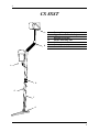
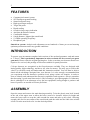
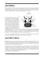
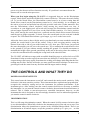
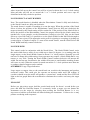
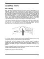
CS8SST
OPERATING INSTRUCTIONS
2
CS 8 SST - RAPID GET YOU GOING
INSTRUCTIONS
SET-UP
Assemble and adjust for length (Twist surplus lead around stem).
2
3
Insert batteries.
Set the controls on the front panel as follows:
• NOTCH (SELECT) Fully anti-clockwise
• NOTCH (WIDTH) Fully anti-clockwise
• DISC 9 o'clock
• POWER 3 o'clock. (This switches the unit on. The right hand LED on the front
panel will illuminate for about one second indicating charged batteries.)
SEARCHING
Keep the search head at a constant height, i.e. do not allow the head to swing higher
above the ground at the right and left edges of your swing.
PINPOINTING
When you hear a tone from the loudspeaker, you have found a target.
• Keep the head close to the ground & move it away from the target.
• Hold the PINPOINT push-button.
• Sweep the head over the target area.
• The sound will be loudest when the head is directly above the target.
THE DISCRIMINATE (DISC) CONTROL
Use to ignore metal in the following order as you turn the knob clockwise:
Iron, Silver Paper (Aluminium foil), new 10p, old 10p, Bottle Cap, £1 coin.
THE NOTCH CONTROLS
Can be set to selectively ignore only certain targets, however, please refer to the full
instructions to use this facility.
IF A PROBLEM IS ENCOUNTERED REFER TO THE FULL INSTRUCTIONS
3
4
CS 8SST
A
B
A
B
C
D
E
F
G
Battery Compartment
Upper Stem & Handle Grips
Din Plug & Socket
Stem Connecting Nut
Cable
Lower Stem
Search Head & Fastener
C
D
E
F
G
4
5
FEATURES
•
•
•
•
•
•
•
•
•
•
•
•
Computerised control system
SST intelligent ground tracking
Smart Scan panel array
High speed target analyser
Target Pin-point
Depth reading
Overdrive large target indication
Anti dust & moisture features
Comfortable balance
8 inch diameter, lightweight search head
12.5KHz operating Frequency
Headphone jack
SmartScan system: Analysis and adjustment occurs hundreds of times per second assuring
optimum performance under any ground conditions.
INTRODUCTION
To protect your investment complete both sections of the enclosed guarantee card and return
to C-Scope. This is particularly important in order to obtain the free second year parts
guarantee. Please retain the original packing box. In the event that your detector should ever
require to be serviced, this package will be most suitable for postal protection.
C-Scope detectors are recognised as the finest detectors available. They are designed with
lasting quality, high technology, and above all, value for money. The only way to realise this
value is to carefully study and understand this instruction manual. You will then be able to
obtain all the advantages designed into your detector. It is also strongly recommended that
you experiment with the detector's operation in air using various test samples, in order to
learn to identify and understand the detector's capabilities and responses. Always remember
that becoming a good metal detectorist is like becoming a good photographer or fisherman,
that is, although it is an advantage to buy the best equipment, having bought it, patience and
hours of practice are needed to become proficient.
ASSEMBLY
Open the carton and remove the main housing assembly. Twist the plastic stem lock, located
at the end of the upper stem to allow the lower stem to be inserted. Adjust for length and
rotate the lower stem to wrap the cable around the stems and take up any slack. Allowing
enough cable for free movement of the search head push the cable into the cable slots to hold
it firm. Turn the stem lock to fix it at the desired position.
5
6
BATTERIES
The CS8SST is powered by eight AA batteries (not supplied) available from garages,
department stores, etc. or a single 12v rechargeable pack from C-Scope. It is advisable to use
standard alkaline batteries to start with. You can then evaluate the sort of use you give the
detector and decide whether the investment in rechargeables is justified.
Battery
Compartment
The batteries should be fitted in the
holder which is located in the battery
CHARGER
HEADPHONE
compartment. To fit new batteries
SOCKET
SOCKET
first check the power switch on the
unit is switched to OFF. Then loosen
the two captive screws located in the
battery cover (do not fully remove
these from the cover) and remove the
cover. Inside is the battery holder.
BATTERY
COMPARTMENT
Lift out the holder and detach the
connector if it is already fitted. Load
it with the eight batteries ensuring
that each battery is inserted the correct way round, (direction of batteries alternating). Roll
each individual battery to ensure it is located correctly and making proper contact. Replace
the connector making sure that it is firm and well seated, and put the loaded holder into the
housing. Fit the cover and tighten the two captive screws finger tight.
Note: Zinc Carbon batteries should not be left in the detector for long periods where they
could leak, so remember to remove them at the end of a day's searching.
BATTERY CHECK
Battery check always occurs at instrument turn on. The Battery Check routine lasts 3 or 4
seconds then the instrument resumes normal operation. New or fully charged batteries should
cause the far right LED to illuminate. If no LEDs are lit the batteries should be recharged or
replaced. Only one LED will be lit at one time.
The LED bar graph is a good representation of battery condition. This means that as the
batteries drain, the LEDs will light from one to the next, right to left. A Ni-Cd pack will
progress down at a rate of 30 - 60 minutes for each LED. Generally when the battery check
reads 5 or 6 you are about halfway through the charge, or life, of that battery pack. The
amount of time varies depending on a number of factors.
For example, to maximise battery life:
6
7
1) Deactivate the SST Scan feature
2)Use headphones
The CS 8 SST has a built in battery monitoring system. This functions continuously during
normal operation. As long as the batteries have sufficient voltage to operate the instrument will
give no indication. However, when the voltage drops low enough to cause erratic or unpredictable
operation, the led bar graph will go blank. At that point there will be no ID or SST Scan (see
later). The audio will function but may not be reliable. When the LEDs blank the operator should
recharge or replace the batteries.
7
8
THE FEATURES IN DETAIL
•
•
•
•
•
•
•
LED Bar Graph
Power/Sensitivity
Discriminate
Pinpoint button
Notch Select
Notch Width
SST Scan
The LED bar graph provides target identification, depth (in inches) and indicates that the
ground Scan is activated.
The Power/Sensitivity control turns the unit on and sets the level of sensitivity. When
searching adjust the knob clockwise until the LEDs begin to lock on as though it something
was detected, then back off slightly until the LEDs go out. This feature will require a little
experimentation to find the best setting.
The Discriminate control eliminates items in the sequence Iron, Silver Paper (aluminium
foil), new 10p, old 10p, Bottle Cap, £1 coin. Sweep a sample of the item you want to
discriminate over the search head while adjusting the control until it is rejected. Make sure
there is no other metal near the search head when setting the Discrimination.
The Pin-Point button can be used to locate the target more precisely and to measure depth.
When pin-pointing, move the search head close to the target, then hold the search head
perfectly still while you depress and hold the button. Sweep the search head in ever shorter
swings until the target response is a mere blip. That is the centre of the target.
Note the position of centre mentally, and then holding the unit slightly off to one side,
depress and hold the button and move towards the centred target. Note the LEDs lighting
from left to right. Each LED indicates the depth of the target in inches and can also be used to
verify the position of the target.
Notch Select and Notch Width both operate in conjunction with the Discriminate control.
These controls work together to notch-in or notch-out selected targets. The range of the
Notch Select is exactly the same as the Discrimination Control. Generally speaking any target
that can be discriminated out by the Discrimination Control can be notched in or out with the
Notch Control. For example, say a target is picked up when the Discriminate Control is at the
1 o’clock position, but when you advance the control to just past the 1 o'clock position, then
the target is rejected. To notch this target simply set the Notch Select to the 1 o’clock
position. This will be true no matter where the target falls out on the Discriminate control.
The width of the notch band is adjusted to the optimum setting with the Notch Width control.
The SST Scan is a visual indication that the detector ground scan is operating (the ground
scan always functions whether the SST Scan is enabled or not). To enable this feature the
pinpoint button should be held down momentarily when the detector is turned on. When
enabled the LEDs illuminate consecutively across the bar graph in a rapid scan movement.
Do not hold the pinpoint button down too long (more than 2-3 seconds) when turning the
8
9
power on or the detector will not function correctly. If a problem is encountered turn the
detector off to reset the microprocessor.
When you first begin using the CS 8 SST it is suggested that you set the Discriminate
control, Notch Select and Notch Width fully counter-clockwise. This turns the notch facility
off. To set the Notch Select, the Discriminate control must be at a lower setting than the
Notch Select control (set the Discriminate control to 9 o’ clock initially). As an example, set
the unit to reject iron and pull-tabs but still pick up nickel and coins of other materials: first,
turn the Discriminate control clockwise while moving the search head over iron. A
screwdriver or your digging tool will work well. Increase the Discriminate control until the
unit no longer responds over iron. Next, set the Notch Width control to 12 o’clock- position.
Now, while moving the search head over a pull-tab, turn the Notch Select control clockwise
until the unit no longer responds. To check, move the search head over the coin and it should
respond. The LED should also indicate a good target, eg A to G on the lower scale.
Adjust the lower stem so that, with the unit in your hand and your arm extended towards the
ground, the search head is just off the surface. Using a slow sweeping motion, swing the
detector from side to side as you walk forward at a very slow pace. The slower you proceed
the more thoroughly you will cover the search area. Try to maintain the search head as close
to the ground as you can without actually touching the ground. You should concentrate to
maintain this height off the ground, particularly at the end of the swing where the tendency is
to raise the search head before starting the swing back in the other direction.
The CS 8 SST will indicate a target with an audible identifying tone as well as lock on a LED.
Sometimes it helps to read a target from more than one direction. Turn 90 degrees over the
suspected target and sweep again. Sometimes the reading will change indicating that the first
reading may be false. Practice will make you more proficient at this technique. In most cases
good targets read the same from any direction and bad targets tend to change.
THE CONTROLS AND WHAT THEY DO
POWER ON/OFF SENSITIVITY
This control turns the instrument on and off, and controls the motion mode sensitivity. Fully
clockwise is the most sensitive position. These instruments have sophisticated programs that
recognise the sensitivity setting and set the instrument for optimum performance. If the
instrument gives a false reading, turn the control counter-clockwise as necessary to stabilise
the instrument. As you turn the control counter-clockwise the maximum detection distance is
reduced. This is similar to non-microprocessor controlled instruments, however, on this
instrument the unit is designed to also increasingly desensitise itself to mineralised ground as
you turn the control counter-clockwise.
DISCRIMINATION
This is a full range discrimination control. When the control is fully counter-clockwise there
is zero discrimination. When fully clockwise the instrument rejects zinc and screw caps. Zero
discrimination allows the instrument to operate in the All Metal Motion Mode. There is no
discrimination at all and all targets, except the ground are picked up. To give you an idea
9
10
where items fall out on the control iron will be rejected at about the 8 or 9 o’clock setting.
Most pull-tabs will fall out at around the 2 or 3 o’clock position and screw caps are
eliminated at the fully clockwise position.
NOTCH SELECT & NOTCH WIDTH
Note: The notch function is disabled when the Discriminate Control is fully anti clockwise,
or the Notch Controls are fully anti clockwise.
The notch feature is capable of notching in or out the target. When the position of the Notch
Select is below the position of the Discriminate Control (but not fully anti clockwise) the
targets selected by the Notch setting will be notched in. If the position of the Notch Select is
above the position of the Discriminate Control, the targets selected by the Notch control are
notched out. As an example, set the Discriminate Control to reject foil. Now set the Notch
Select to reject Pull-Tabs. It is possible to set the Notch Width so that Pull-Tabs through to
Screw Caps are rejected. This approache works well for rejecting or accepting (ie picking up)
certain targets or bands of targets. To turn off the notch feature, turn the Notch Select and
Notch Width both fully counter-clockwise.
NOTCH WIDTH
This control works in conjunction with the Notch Select. The Notch Width Control varies
the notch width from a notch of zero width up to about 30 degrees. As a starting point for
single targets, set the Notch Width Control to about 12 o’ clock position. Normally you will
not have to change this width setting. Some operators may require a Notch Width that is very
narrow or very wide. Turning the Notch Width Control counter-clockwise will narrow the
width. Do not turn too far otherwise the width will become to small and the notching feature
will cease to work. When the control is turned toward the 5 o’ clock position more than one
or perhaps a band of targets can be notched.
OVERDRIVE Large Target Indication
Large targets or targets close to the search head can overdrive the instrument and produce
erroneous results. This could give the operator an incorrect audio and LED reading. If
overdrive should occur the audio will produce a “motor boat” sound and the Error LED will
light on the bar graph. Raise the search head to eliminate the overdrive and sweep the target
again.
PIN-POINT
Before you pin-point a target, hold the search head steady for about 1 second before you
press and hold the Pin-Point button. To accurately locate a target you can detune the
instrument over the target by releasing then pressing the Pin-Point Button. It is very
important to hold the search head still when detuning the instrument Failure to do so may
produce confusing audio responses.
10
11
GENERAL HINTS
Pin-Pointing
When pinpointing it is important that the search head is held still while pushing in and
holding the detune button. Hold the search head close but not directly over the suspected
centre and while keeping the search head stationary, depress the button. Now, sweep towards
the centre of the target. Repeat this procedure until the response is a short audio blip and that
will be the centre of the target. To verify the reliability of your target, it is a good practice to
check it from another angle. Try to ID the same target at 90 degrees from your first reading.
Also, by holding the pinpoint button in and checking depth, you can check that you have
correctly centred over the target. When the target reads the shallowest depth, that is the centre
of the target. Always use care in retrieving the target so as not to damage your find.
(i) The strongest signal will always be received when the object is directly beneath the centre
of the head (see X in the diagram below). To pinpoint the find, stop the search head when
you are directly over the target object, then move the search head through 900 and sweep
again, thus forming a cross with the two sweeps as shown in the diagram.
(ii) To ‘focus’ the target signal still further raise the search head, retuning if necessary, and
pass the search head over the object until only a faint signal is heard.
The faint signal will then be occurring at a point X under the centre of the head (see
diagram). More accurate pinpointing, particularly of deep buried objects can be achieved by
finding the centre of the target object as described above and making a mental note of the
position.
Turning your detector through 900 and sweeping across the target again will give a second
reading, accurately determining the centre of the object.
Digging carefully at point X will reveal the find.
11
12
Detection Range
Your CS8SST is a top performance detector but adverse soil conditions can significantly
reduce the depth of detection.
Detection ranges will vary depending on the size of the object, the length of time an object
has been buried, and the type of ground the object is buried in.
The best ground conditions are well compacted soils and coins can be found at the greatest
depth if the object has been buried for some time and the coin has interacted with the salts in
the ground, thereby appearing larger to the detector. The worst conditions for detecting are on
loosely compacted or freshly dug ground or when the object has only recently been buried. In
these conditions detection range will be reduced. 90% of all artefacts are found within 6" of
the surface.
Determining the Target Size
An operator who is familiar with his instrument will be able to do an excellent job of
determining object size, shape and depth before he digs. This technique is learned from
careful analysis of the LED bar graph and audio signal coming from the detector. Each time a
signal is heard, listen for any peculiar characteristics it may have, determine over how large
an area you get a detector signal, and try to 'outline' the object before you dig.
After digging up the object, compare the object size, shape, depth and position in the ground
with signal information you received before digging. After careful analysis of many signals
you will learn to 'read' the hidden target before digging.
12
13
OPTIONAL ACCESSORIES from C-Scope
Headphones:
Headphones not only extend battery life but improve sensitivity by cutting extraneous noise.
The headphones should be fitted with a standard stereo 1/4 inch (6.35 mm) jack plug. The
headphone socket is located under the protective cap in the battery housing.
Rechargeable battery pack:
A shrink wrapped pack of 8 rechargeable Nickel Cadmium batteries to replace the standard
batteries and holder.
Battery charger:
The C-Scope battery charger is designed to charge the rechargeable pack quickly and safely.
Search head cover:
This provides protection to the underside of the search head when detecting in muddy or
stony conditions.
CHARGING BATTERIES
A battery charge socket is provided for use with the C-Scope battery charger (see
Accessories) and is located under the protective cap in the battery housing. (The smaller of
the two sockets.) Inserting the charger will automatically remove the power from the detector
so the charger must be removed to do a battery check. Do not attempt to recharge standard
batteries. It will take between eight and fifteen hours to fully recharge flat batteries with the
C-Scope charging unit.
For further information, and a price list, for all C-Scope accessories please telephone
(01233) 629181, or contact your local dealer.
13
14
THE IMPORTANCE OF THE RIGHT
APPROACH
Treasure hunting can be a profitable and rewarding hobby, if approached in a patient and
diligent manner. Time spent researching to locate a worthwhile site for a search can be time
wasted if your search is hasty and erratic. To achieve maximum results it is important then, to
decide on your approach to any particular site in advance of the actual search.
Tactics will be decided by the type of site - it is more profitable to scan a small area
thoroughly than to conduct a haphazard search of the total site. However, when the site is too
far away for you to make several return visits, a plan should be adopted which gives
maximum coverage, at the same time as indicating the most likely area for detailed search.
Your detector alone is not a guarantee of successful treasure hunting. Any detector needs an
operator and for the best results the operator needs the right approach, attitude and technique.
Too many beginners neglect the importance of pre-planning and research before using their
detector in the field, and patience and technique during the actual search.
A successful search should begin with research some time before the day of the actual search.
The extent and thoroughness of your research will be one of the major factors in the success
of your detecting. You should aim to get as complete an understanding as possible of the
local history and geography.
The key to the choice of site is to think of people, where they congregated over the past few
hundred years. What were their customs and pursuits? Where did they spend money? Where
did they carry money? The answers are not Roman sites, nor are they associated with mystic
treasure stories of crocks of gold. Rather, they are unassuming, undramatic places, like public
footpaths and ancient rights of way, old houses and so on.
When you have chosen your site, allocate a whole day from early morning to early evening
for the search. Make sure you have all the equipment you are likely to need. Your detector
should be checked before starting out, and you should always carry a spare set of batteries.
You will also need a strong, sharp trowel. It is also a good idea to have a set of lines and pins
so that you can lay out your search area scientifically.
Most beginners make the mistake of rushing about hoping to chance upon a rare find. If for
example there happened to be a valuable ring that was buried 4" deep on the site you were
searching, if you rushed about haphazardly and quickly on the site, the odds would be very
much against you finding it. On the other hand, if you pegged out the area scientifically and
searched slowly and thoroughly, the odds of finding the ring would be very much more in
your favour.
Remember, BE PATIENT and WORK SLOWLY. Do not try to cover too large an area,
restrict yourself to a small area and work through it thoroughly. Make a note of the position
and the extent of the area, and then when you return you can start again further on without
missing any ground or covering the same area twice.
14
15
It is also important to keep the detector head as close to the ground as possible. Ideally, you
should 'iron' the ground with the search head of the detector, so that you do not lose any
detection range. Similarly, if you work slowly and carefully you should be able to distinguish
the faint signals as well as the clear-cut signals and further increase your finds.
The technique of getting the best out of your detector is not learnt overnight. You need to get
as much experience as possible so that you can recognise every kind of signal. Indeed, a good
detector operator can often tell you what is being detected before it is unearthed.
Search Head Position
A
B
C
D
It is essential that the search head is kept close and parallel to the ground as in B. Do not hold
the search head too high above the ground, or at an odd angle as in A, C, D as you will be apt
to miss finds.
SWEEPING TECHNIQUE
For extremely small object searching, such as coins, rings, nuggets, etc. lower the search
head to within 1 inch of the ground. Sweeping the coil from side to side in a straight line in
front of you. Keep the coil at a constant height as you sweep from side to side. Move the head
at a rate of 0.5 metre per second.
The optimum sweep rate must be determined by each operator. The detector should be held
comfortably in the hand, with the head held as closely to the ground as possible. As the
detector is scanned from side to side in front of the operator, the search head should be
advanced approximately two-thirds the diameter of the coil. This keeps the operator moving
ahead, and it allows some overlapping of each sweep. This overlapping ensures that nothing
will be missed. It is well to note here that the operator should not rush. This is one of the
most common mistakes made by detector users. If you rush, you will not adequately cover
the ground.
15
16
CODE OF CONDUCT
1. Do not trespass. Ask permission before venturing on to any private land.
2. Respect the Country Code. Do not leave gates open when crossing fields, and do not
damage crops or frighten animals.
3. Do not leave a mess. It is simple to extract a coin or other small objects buried a few
inches under the ground without digging a great hole. Use a sharpened trowel or knife to
cut a neat circle or triangle (do not remove the plug of earth entirely from the ground);
extract the object; replace the soil and grass carefully and even you will have difficulty in
finding the spot again.
4. Help to keep Britain tidy - and help yourself. Bottle tops, silver paper and tin cans are the
last thing you should throw away. You could well be digging them up again next year. Do
yourself and the community a favour by taking the rusty iron and junk you find to the
nearest litter bin.
5. If you discover any live ammunition or any lethal objects such as an unexploded bomb or
mine, do not touch it. Mark the site carefully and report the find to the local police.
6. Report all unusual historical finds to the landowner.
7. Familiarise yourself with the law relating to archaeological sites. Remember it is illegal
for anyone to use a metal detector on a scheduled ancient monument unless permission
has been obtained from the Historic Buildings and Ancient Monument Commission for
England or the Secretary of State for the Environment in Scotland and Wales.
8. Remember that when you are out with your metal detector, you are an ambassador for our
hobby. Do nothing that may give it a bad name.
9. The law relating to treasure finds must be followed. Details of the law can be obtained
from the Department of Culture, Media & Sport (Tel: 0171 211 6200) who produce
excellent literature to help you to understand how the law affects you and your hobby.
CARE OF YOUR DETECTOR
Storage
When not in use your detector should be stored in a dry warm environment. If it is not to be
used for a certain length of time it is advisable to remove the batteries to avoid leakage which
could cause serious damage. The working life of your detector will be shortened by careless
use or neglect of the unit. Think of your detector as a scientific instrument. Your detector is
designed to withstand rugged handling on any terrain, but misuse or lack of due attention will
tell in the end. After using your detector in a hostile environment (salt water, sand, etc.) The
exterior parts should be flushed with clean fresh water, paying particular attention to the head
and stems, then carefully wipe dry.
16
17
TROUBLESHOOTING
(a) Check the condition of batteries under load using the LEDs. (See Battery Check
Procedure).
(b) Check that the search head is properly attached to the control box via the search head
cable connector.
(c) Interchange batteries and ensure connections are correct and secure. Battery life can
vary tremendously between makes, therefore your 'new' batteries may already be
insufficiently powerful to run the detector.
Oscillating Signal Accompanied By LED Fluctuation
(a) This could be due to poor battery connections. Ensure that they are tight and the
batteries are securely clipped into place.
(b) Loose search head cable connection - tighten.
(c) Interference from a vehicle using a radio transmitter or possibly a stationary source of
electromagnetic radiation - if this occurs then reduce the sensitivity. If the problem
persists then the best remedy is to wait until the transmission stops.
Intermittent Sound From Speaker
(a) This could be due to poor battery connections. Ensure that they are tight and the
batteries are securely clipped into place.
(b) Loose search head cable connection - tighten.
(c) Radio interference (see above).
Further Information
If you experience any difficulty in operating your CS8SST, or have any questions on the
information in your CS8SST Operating Instructions Manual, please do not hesitate to phone
our Customer Service Department on (01233) 629181.
Before returning a detector for repair to C-Scope ensure you have done the
following:(a) Read the instructions thoroughly.
(b) Tried new batteries and checked procedure outlined above.
(c) Return your detector with a letter giving full details of fault.
This equipment conforms to the EMC Directive 89/336/EEC.
However, system performance may be impaired by unusually strong electromagnetic fields.
17
18
Kingsnorth Technology Park, Wotton Road, Ashford, Kent TN23 6LN
Telephone: (01233) 629181 Fax: (01233) 645897
Issue 1 (10/97)
18