1
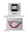
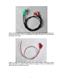
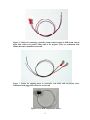
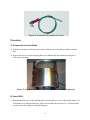
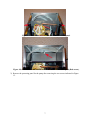
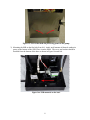
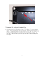
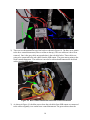
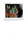
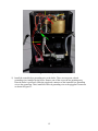
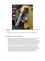
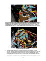
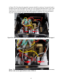
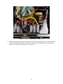
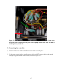
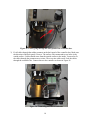
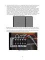
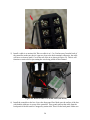
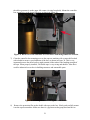
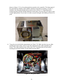
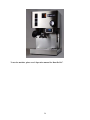
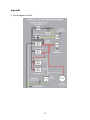
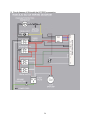
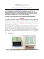
KIT-RSPb Installation Guide
Version 1.4
Auber Instruments, 730 Culworth Manor, Alpharetta, GA 30022
Tel: 770-569-8420
e-mail: [email protected]
www.auberins.com
This is a PID controller kit installation guide solely distributed to our clients, who have
purchased the KIT-RS kit. Once you are done with this guide, please send us your feedback,
comments, and/or suggestions (via e-mail to [email protected]) so that we may continue
making improvements to this guide. Your help is greatly appreciated!
Note: Please read through the entire guide before attempting any kind of installation.
Disclaimer:
This product was created and distributed by Auber Instruments Inc. Everything included in this
guide (images, text, etc.) is the intellectual property of Auber Instruments Inc. Thus, this guide is
not to be replicated, altered, or sold without express written permission from Auber Instruments
Inc. If you did not receive this document from Auber Instruments Inc, please let us know as it is
subject to inaccuracy and/or obsolescence. The Rancilio Silvia names and trademarks are owned
by Rancilio Macchine per caffè. S.p.A.
The modifications of Rancilio Silvia involve tampering with high-wattage electrical circuits in a
wet environment, which could result in electric shock, burns, other serious personal injury or
death, as well as fire, explosion and other property damage. This kit is for users with proper
electrical safety knowledge only. Attempting to access your espresso machine will void its
warranty. You, the user, will assume full responsibility for any modifications undertaken. Auber
Instruments Inc is not liable for any damage caused to your property as a result of improper use.
Parts Identification.
Figure 1. PID Controller, Aluminum extrusion box, rubber grommet, double sided tape
pre-assembled - Front view on left. Back view on right.
1
Figure 2. Dual Solid State Relay (SSR), mounting screw, nut and washer. The dual SSR
in the kit contains two SSRs in one package. The left side will be used for steam control
and the right side will be used for brew control.
Figure 3. Pair of red cables for connecting SSR output to the cables that used to be on
the brew thermostat. They are terminated with female disconnect on end and male
disconnect on the other.
2
Figure 4. Pair of black cables for connecting SSR output to the cables that used to be on
the steam thermostat. They are terminated with female disconnect on end and male
disconnect on the other.
Figure 5. Cables for connecting controller brew control output to SSR brew control
input. Red cable is for positive. White cable is for negative. They are terminated with
female disconnect terminal on one end.
3
Figure 6. Cables for connecting controller steam control output to SSR steam control
input. Red cable is for positive. Blue cable is for negative. They are terminated with
female disconnect terminal on one end.
Figure 7. Cables for tapping power to controller. One black and one brown color,
terminated with piggyback connector on one end.
Figure 8. The RTD temperature sensor..
4
Figure 9. Cable ties
Figure 10. Brew pump control cable. Green
Figure 11. Left, silicone heat transfer compound (white paste in the vial) for SSR and
sensor, Middle, RTD jumper cable, white. Right, jumper cable for brew pump control,
black.
5
Figure 12. Controller box ground wire. Green
Procedure
A. Preparation for installation.
1) Disconnect the power cord from power outlet. Remove the water tank, portafilter, and drip
tray.
2) Remove the top cover after removing the screws indicated by the red arrows in Figure 13.
Pull out the top panel.
Figure 13. Top panel. Red arrows indicate the screws that hold the top panel.
B. Install SSR.
1) Remove the back panel of the machine after removing the two screws indicated in Figure 14a.
Loosen the screw indicated in Figure 14b by several turns (do not remove it). The back panel
can be removed by sliding it back and lifting up.
6
Figure 14a. Red arrow indicates the screw that hold back panel.
Figure 14b. The screw on the bottom of machine that holds the back panel (Red arrow).
2) Remove the protecting panel for the pump after removing the two screws indicated in Figure
15.
7
Figure 15. Screws that hold the protecting panel for the pump.
3) Mounting the SSR on the first hole from left. Apply small amount of thermal conductive
grease to the bottom of the SSR. Place it on the metal. The screw and washer should be
installed from the bottom of the base as shown in Figure 16a and 16b.
Figure 16a. SSR mounted on the base.
8
Figure 16b. Bottom view of the SSR mounting screw.
C. Connecting SSR Cables and Grounding Wire.
1) Connecting the cables to SSR as shown in Figure 17. The left side is for steam temperature
control. The two black cables are connected to the output. The blue cable is connected to the
negative of the input. Red cable is connected to the positive of the input. The right side is for
the brew temperature control. The two red thick cables are connected to the output. The
white cable is connected to the negative of the input. Red cable is connected to the positive
of the input.
9
Figure 17. Connection of the cables to SSR
2) There are two thermostats on top of the boiler as shown in Figure 18. The blue arrow points
to the brew control thermostat (it has a red dot on the top). The two cables on it have been
removed. One is the gray cable on top and other is the red cable below. These cables are
going to be connected to the red cables from the SSR output. The green arrow points to the
steam control thermostat. The cables on it need to be removed and connected to the black
cables from the SSR output.
Figure 18. Brew control thermostat and steam control thermostat
3) As shown in Figure 19, the blue arrows show the red cables from SSR output are connected
to the cables originally were on the brew control thermostat. The green arrows show the
10
black cables from the SSR output are connected to the cables that originally were on the
steam control thermostat.
Figure 19. SSR output connections to thermostats cable
4) Tie up the cables with the cable tie as shown by the red arrows. The green arrow shows that
the SSR input cables are introduced to the front of the espresso machine through the gap
around the steam wand (see Figure 20 below for more details).
11
Figure 20. Tied up the cables
5) Install the controller box grounding wire to the boiler. There are two green colored
grounding wires installed on the boiler. Remove one of the wires (the one pointing away
from the boiler is preffered). Slide the piggyback connector of the controller box grounding
wire to the ground tap. Then, install the removed grounding wire to the piggyback connector
as shown in Figure 21.
12
Figure 21. Install the controller box grounding wire to the boiler. Red arrow shows its
position
6) Reinstall the protecting panel for the pump and the back panel to its original position.
D. Installation in the Top Compartment.
1) Install the RTD sensor. The RTD sensor should sit in the same place as the original brew
thermostat was located (indicated by the blue arrow in Fig 18). Remove the brew
thermostat by loose the screws that hold it. Insert the RTD sensor to the same bracket that
was used to hold the brew thermostat. Sometimes, it is convenient to work on the screws
by temporarily removing the cable connector on the left side terminal of the heater (green
arrow on Figure 22b). Please note that if the machine is old and as a result, the plastic
protection guard of the heater connector is brittle, it might break off and leave some
unprotected spots. You need to use a small to medium sized flat head screw driver to
remove the screw. Be very careful to not let it drop into the gap below. If it drops to the
top of the grouphead, it could be a lot of trouble to take it out. A magnetized screw driver
will help. Apply a small amount of silicone heat transfer compound to the bottom of the
RTD sensor before installation. This will ensure a fast and accurate temperature
measurement. Fig 22a shows the RTD has been installed (marked with red arrow).
13
Figure 22a. Red arrow shows the RTD sensor installed in the bracket that was for the brew
thermostat. The cable to the heater has been removed for easy installation (green arrow).
When installing the cable back, be sure to push the connector all the way in. Failure to
installed the cable back to its original position might result in cable overheat and damage.
Figure 22b. RTD sensor installed
2) The power for the controller box is tapped from the main power switch by using the
piggyback connectors on the black and brown cables. Remove the connectors with black and
red cables on the main power switch (red arrows in Figure 23a). Remember the original
position: the connector with black cable was on the left and connector with red cable in the
center. Slide the two controller power cable piggyback connectors on to the switch as shown
14
in Figure 23b. The tab on the piggyback connector should be on the top. You need to bend it
downward a little bit if the angle is too high. It is very important that black cable is put on the
left side of the switch and brown cable on right. After installing the connectors, connect the
cables that were just removed to the tab on the piggyback connector. It is very important to
keep the original position, black on the left and red in the center (see Figure 23c)
Figure 23a. Red arrow indicates the connectors that controller power cable will be tapped.
Figure 23b. The controller power cable piggyback connector location. (red arrows).
Brown cable on the right and black cable on the left.
15
Figure 23c. Put the original power cables back.
3) Install brew pump control cable. Remove the white colored cable from brew switch. Connect
the green colored brew pump control cable to the white cable and hold it in stable place by
tying it up to the other cable near by (see Figure 24).
16
Figure. 24. Red arrow shows where the white cable has been removed. Green arrow
shows the cable is connected to the green colored pump control cable. They are hold to
a stable place by a cable tie.
E. Connecting the controller.
1) Remove all 8 screws on the controller box. Save them in a safe place.
2) Fit the steam control cables, controller power cables and RTD sensor cables to the outside
through the gap around the steam wand (red arrow in Figure. 25).
17
Figure 25. Cables going through the back panel of the controller box.
3) Fit all cables through the rubber grommet on the back panel of the controller box. Make sure
the direction of the back panel is correct. The surface with countersunk screw holes is the
outside surface. Cables should come from the outside surface to the inside. You need to fit
the cables through the grommet one at a time. There are nine cables total. Feed the cables
through the controller box. Connect them to the controller as shown in Figure 26.
Figure 26. Connecting the wire to controller
18
4) Wiring the controller correctly is a very critical step. Failure to install it correctly can cause
damage to the machine and electric shock. The terminal numbers are printed on labels
located on both sides of the controller. The brown colored power cable needs to be
connected to terminal 1. The black colored power cable needs to be connected to terminal 2.
Connect the brew pump control jumper cable between terminal 2 and 4. The green colored
brew pump control cable needs to be connected to terminal 5. Both red colored cables from
SSR are connected to terminal 10. The white colored cable for SSR input is connected to
terminal 9. The blue colored steam control cable connects to terminal 3. The clear RTD
cables need to be connected to terminal 7 and 8. The white colored RTD jumper cable needs
to be connected to terminal 6 and 7. Please refer to Table 1 and Figure 27a for details
Table 1. Wiring to the controller
Color code of wire
Brown power cable
Black power cable
Black jumper cable
Blue steam control cable
Green (brew pump control cable)
White RTD jumper cable
Clear RTD cables
White SSR input cable
Red cables from SSR
Terminal
1
2
2&4
3
5
6&7
7&8
9
10
Bending the wire tip will make the insertion of the cable easier as shown in Figure 27b. In
order to prevent the cables from coming loose when pulling on them during box installation,
make sure all cables are securely tightened by a screw driver. Also, make sure there are no
small wires touching the other terminals, causing a short circuit.
.
Figure 27a. Detailed view.
19
Figure 27b. Bend the wire for easier insertion.
5) Install a cable tie as strain relief. Place a cable tie at 1.5 to 2 inches away from the back of
the controller (make sure the tie is not too close to the back terminals, otherwise, the cable
will have no room to bend). Cut off the tail of the tie as shown in Figure. 28. This tie will
function as strain relief to preventing the wire being pulled off the terminal.
.
Figure 28. Install a cable tie as strain relief (red arrow)
6) Install the controller to the box. Screw the front panel first. Make sure the surface of the box
with double sided tape is on top of the controller. Then, gently pull out the cable from the
back panel of the box until it is stopped by strain relief. Screw on the back panel. Make sure
20
the rubber grommet is on the upper left corner (viewing from back). Mount the controller
box ground wire to the lower left screw as shown in Figure 29.
Figure 29. Back view of the controller box. Red arrow indicated ground wire location.
7) Clean the controller box mounting area on the espresso machine with a cotton ball soaked
with alcohol to ensure a good adhesion of the box, as shown in Figure 30. This is very
important because the metal surface might contain oil that reduces the bonding strength of
the tape. When properly installed, 3M double tape is very strong and durable. It has been
used for industrial use such as in building structures and automobile parts.
Figure 30. Cleaning the box mounting area with alcohol.
8)
Remove the protection film on the double side tape on the box. Slowly and carefully mount
it on the espresso machine. Make sure there is a gap between the group head and box as
21
shown on Figure 31. It is for reducing the heat transfer to the controller. The front panel of
the controller box should be flush with the machine front panel for neatness. For the V3
machines, the front panel might need to come out by as far as 1/8”, depending on the
rotation position of the hex nut that holds the steam wand. You have only one chance to put
it in the right position. If you remove it and try to put back again, the bonding will not be as
good.
Figure 31. Control box position.
9) Tie up the wire in the boiler compartment (see Figure 32). Make sure there are no cables
touching the boiler surface. This is especially important for the cables installed by the
factory. The cables installed by the factory have PVC insulation that will melt when
touching the hot boiler surface. It can result in electric shock.
Figure 32. Tie up the cables.
22
10) Before re-installing the top cover, cut the excess tail of the cable ties. Check all connections
that have been changed. Make sure that there are no exposed wires or connectors that will
touch the top cover metal when it is installed. Some of the cables that stayed above the level
of the cover when fitted will move when the cover is installed. If that cable has an exposed
metal connector, it could result in an electric short.
11) Install the water tank.
The project is done. This is how the machine should look like now. The top machine has the
standard controller with red LED. The bottom machine has the optional controller with blue LED.
23
To use the machine, please read “Operation manual for Rancilio Kit”.
24
Appendix
1) Circuit diagram of Silvia.
25
2) Circuit diagram of Silvia with the KIT-RSPa connection
26