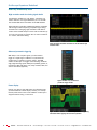
1
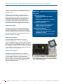
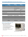
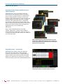
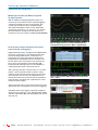
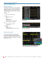
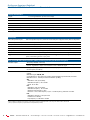
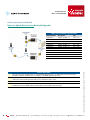
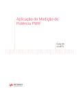
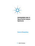
Oscilloscope Experience Redefined: Experience the speed, usability, and integration
Imagine an oscilloscope that sees everything, triggers on
anything, has the ease-of-use of a tablet device…and grows
with your projects.
The 4000 X-Series oscilloscopes are engineered for nextgeneration performance, delivering waveform update rates
20 times faster than the competition to display the most
signal detail. An industry-leading 12.1-inch capacitive touch
screen with innovative hardware-based InfiniiScan Zone
touch triggering provides the most intuitive interface to get
you answers faster. The 4000 X-Series provides maximum
investment protection with fully upgradable 5-instruments-in-1.
Series
ation
Experience the Speed
Anomalies and elusive events are the toughest to debug.
The 4000 X-Series oscilloscope redefines your debugging
experience with MegaZoom IV smart memory technology.
The industry-leading 1-million-waveforms-per-second update
rate, means you see more of your signal behavior and can
feel more confident in your design.
Ihr Spezialist
Spezialist für
für
Ihr
Mess- und
und Prüfgeräte
Prüfgeräte
Mess-
4000 X-Series - Oscilloscope experience redefined:
InfiniiVision 4000 X-Series
Oscilloscopes
Key features:
• Experience the speed:
· One million waveforms per second
update rate
· MegaZoom IV smart memory technology
· Standard segmented memory
• Experience the usability:
· Industry’s first capacitive touch screen
· Industry’s largest 12-inch display
· InfiniiScan Zone touch trigger
• Experience the integration:
· Industry’s first 5 instruments in 1
· Industry’s first fully upgradable including
bandwidth to 1.5 GHz
· Industry’s leading application solutions
Data sheet
Experience the Usability
You may be surprised just how easy it is to use the
InfiniiVision 4000 X-Series. A 12.1-inch capacitive touch
screen − the industry’s largest − works just like your favorite
tablet or smart phone, so debugging your devices is faster
than ever before. Innovative InfiniiScan Zone touch triggering
makes triggering on anything a snap. Just draw a box around
signals of interest and the oscilloscope triggers on them. So,
if you can see it, you can trigger on it.
Experience the Integration
The 4000 X-Series further redefines your oscilloscope
experience by integrating the capabilities of five instruments
in one: oscilloscope channels, logic channels, digital
voltmeter (DVM), dual-channel WaveGen function/arbitrary
waveform generator, and serial protocol analyzer including
USB. All are upgradable, including bandwidth, for the
ultimate investment protection.
Figure 1: MegaZoom IV smart memory technology enables the
speed, usability, and integration.
2
GRÖSSER. SCHNELLER. MEHR MÖGLICHKEITEN.
Oscilloscope
Experience
Redefined:
Erleben Sie die einzigartige
Kombination aus
Geschwindigkeit,
Benutzerfreundlichkeit und Integration.
Experience the speed, usability and integration
dataTec ▪ ▪▪ Ferdinand-Lassalle-Str.
Ferdinand-Lassalle-Str.
▪▪ 72770
Reutlingen
▪▪ Tel.
07121
51
50
▪▪ 07121
Fax
// 51
▪▪ [email protected]
▪▪ www.datatec.de
dataTec
Ferdinand-Lassalle-Str.
52▪ 72770
72770
Reutlingen
Tel.
07121
5150
50▪50
50
Fax 07121
07121
51
50
10
[email protected]
www.datatec.de
dataTec
5252
Reutlingen
▪ Tel.
07121
/ 51 //50
Fax
/ 51 50
1050
▪ 10
[email protected]
▪ www.datatec-gruppe.de
Oscilloscope Experience Redefined: Experience the speed, usability, and integration
Imagine an oscilloscope that sees everything, triggers on
anything, has the ease-of-use of a tablet device…and grows
with your projects.
The 4000 X-Series oscilloscopes are engineered for nextgeneration performance, delivering waveform update rates
20 times faster than the competition to display the most
signal detail. An industry-leading 12.1-inch capacitive touch
screen with innovative hardware-based InfiniiScan Zone
touch triggering provides the most intuitive interface to get
you answers faster. The 4000 X-Series provides maximum
investment protection with fully upgradable 5-instruments-in-1.
Experience the Speed
Anomalies and elusive events are the toughest to debug.
The 4000 X-Series oscilloscope redefines your debugging
experience with MegaZoom IV smart memory technology.
The industry-leading 1-million-waveforms-per-second update
rate, means you see more of your signal behavior and can
feel more confident in your design.
4000 X-Series - Oscilloscope experience redefined:
Key features:
• Experience the speed:
· One million waveforms per second
update rate
· MegaZoom IV smart memory technology
· Standard segmented memory
• Experience the usability:
· Industry’s first capacitive touch screen
· Industry’s largest 12-inch display
· InfiniiScan Zone touch trigger
• Experience the integration:
· Industry’s first 5 instruments in 1
· Industry’s first fully upgradable including
bandwidth to 1.5 GHz
· Industry’s leading application solutions
Experience the Usability
You may be surprised just how easy it is to use the
InfiniiVision 4000 X-Series. A 12.1-inch capacitive touch
screen − the industry’s largest − works just like your favorite
tablet or smart phone, so debugging your devices is faster
than ever before. Innovative InfiniiScan Zone touch triggering
makes triggering on anything a snap. Just draw a box around
signals of interest and the oscilloscope triggers on them. So,
if you can see it, you can trigger on it.
Experience the Integration
The 4000 X-Series further redefines your oscilloscope
experience by integrating the capabilities of five instruments
in one: oscilloscope channels, logic channels, digital
voltmeter (DVM), dual-channel WaveGen function/arbitrary
waveform generator, and serial protocol analyzer including
USB. All are upgradable, including bandwidth, for the
ultimate investment protection.
2
Figure 1: MegaZoom IV smart memory technology enables the
speed, usability, and integration.
dataTec ▪ Ferdinand-Lassalle-Str. 52 ▪ 72770 Reutlingen ▪ Tel. 07121 / 51 50 50 ▪ Fax 07121 / 51 50 10 ▪ [email protected] ▪ www.datatec.de
Oscilloscope Experience Redefined: Experience the speed, usability, and integration
Overview of Agilent InfiniiVision X-Series oscilloscopes
InfiniiVision
4000 X-Series
InfiniiVision
3000 X-Series
InfiniiVision
2000 X-Series
Analog channels
2 and 4
2 and 4
2 and 4
Bandwidth (upgradable)
200, 350, 500 MHz, 1 GHz, 1.5 GHz
100, 200, 350, 500 MHz, 1 GHz
70, 100, 200 MHz
Digital channels
16 (MSO models or upgrade)
16 (MSO models or upgrade)
8 (MSO models or upgrade)
Maximum sample rate
5 GSa/s
5 GSa/s (1-GHz models)
4 GSa/s (100-500 MHz models)
2 GSa/s
Maximum memory depth
4 Mpts (standard)
2 Mpts (standard),
4 Mpts (option)
100 kpts (standard),
1 Mpts (option)
Waveform update rate
> 1,000,000 waveforms per second
> 1,000,000 waveforms per
second
> 50,000 waveforms per
second
Display
12.1-inch capacitive touch display
8.5-inch display
8.5-inch display
InfiniiScan Zone touch trigger
Standard
No
No
WaveGen 20-MHz function/
arbitrary waveform generator
Dual-channel AWG (option)
Single-channel AWG (option)
Single-channel function
(option)
Integrated digital voltmeter
Yes (option)
Yes (option)
Yes (option)
Search and navigate
Yes
Yes
No
Serial protocol analysis
Yes (optional: ARINC 429, CAN-dbc, Yes (optional: ARINC 429, CAN
FlexRay, I2C, I2S, LIN, MIL-STD-1553, FlexRay, I2C, I2S, LIN, MILSPI, UART/RS232, USB 2.0)
STD-1553, SPI, UART/RS232)
Yes (optional: CAN, I²C, LIN,
SPI, UART/RS232)
Segmented memory
Standard
Yes (option)
Yes (option)
Mask/limit testing
Yes (option)
Yes (option)
Yes (option)
Power analysis
Yes (option)
Yes (option)
No
USB 2.0 signal quality test
Yes (option)
No
No
HDTV analysis
Yes (option)
Yes (option)
No
Advanced waveform math
Standard
Yes (option)
No
Connectivity
Standard USB2.0, LAN, video out
(GPIB option)
Standard USB2.0 (LAN/Video
option) (GPIB option)
Standard USB2.0 (LAN/Video
option) (GPIB option)
Need more memory, bandwidth, analysis or bits?
Consider the Infiniium 9000A and 9000 H-Series
•
•
•
•
•
•
•
•
•
•
600 MHz, 1 GHz, 2.5 GHz, 4 GHz (A-Series)
250 MHz, 500 MHz, 1 GHz, 2 GHz (H-Series)
Up to 20 GSa/s (A Series), up to 10 GSa/s (H-Series)
20 Mpts (A Series), 50 Mpts (H-Series) per channel standard
Up to 1 Gpts optional (A Series), up to 500 Mpts optional (H-Series)
4 channel + 16 digital channel (MSO or upgrade)
Up to 12 bits of vertical resolution (H-Series)
Industry’s largest 15-inch touch display
Industry’s only serial protocol viewer with multi-tab viewing
Widest range of applications including serial compliance,
jitter analysis and more.
Figure 2: Infiniium 9000 Series oscilloscope.
3
3
dataTec ▪ Ferdinand-Lassalle-Str. 52 ▪ 72770 Reutlingen ▪ Tel. 07121 / 51 50 50 ▪ Fax 07121 / 51 50 10 ▪ [email protected] ▪ www.datatec.de
Oscilloscope Experience Redefined:
Experience the Speed
One million waveforms per second update rate
If you can’t see the problem, it is hard to troubleshoot
it. With an industry-leading one million waveforms
per second update rate, the InfiniiVision 4000 X-Series
gives you the highest probability of capturing random
and infrequent events that you would miss on an
oscilloscope with a lower waveform update rate.
Powered by MegaZoom IV smart memory technology,
the InfiniiVision 4000 X-Series not only lets you see
more waveforms, but it has the uncompromised ability
to find the most difficult problems in your design. Unlike
other oscilloscopes, uncompromised ability means:
•
•
•
•
•
Always-fast, responsive operation
No slowdown with logic channels on
No slowdown with protocol decoding on
No slowdown with math functions turned on
No slowdown with measurements turned on
Figure 3: The 4000 X-Series captures a glitch occurring once in
a million waveform cycles.
What is waveform update rate and why is it important?
As oscilloscopes acquire data, process it, and plot it to the screen, there is inevitable “dead time,” or the time oscilloscopes
miss signals completely. In general, the faster the waveform update rate, the shorter the dead time. The shorter the dead
time, the more likely an oscilloscope is to capture anomalies and infrequent events. This is why it is critical to select an
oscilloscope with a fast waveform update rate.
Figure 4: Other vendor’s oscilloscope with 50,000 waveforms/second. A long dead time decreases your chances of
capturing infrequent events.
Figure 5: InfiniiVision 4000 X-Series with 1,000,000 waveforms/second. A short dead time increases your chances
of capturing infrequent events.
4
4
dataTec ▪ Ferdinand-Lassalle-Str. 52 ▪ 72770 Reutlingen ▪ Tel. 07121 / 51 50 50 ▪ Fax 07121 / 51 50 10 ▪ [email protected] ▪ www.datatec.de
Oscilloscope Experience Redefined:
Experience the Speed
Agilent achieves this industry-leading waveform update rate with MegaZoom IV smart memory technology
Traditionally, CPU processing was the major bottleneck for
oscilloscope waveform update rate and responsiveness.
Typically, the CPU handles interpolations, logic channel
plotting, serial bus decoding, measurements and more,
and the waveform update rate drops dramatically as these
features are turned on.
The InfiniiVision 4000 X-Series requires minimum support
from a CPU, as most core operations are handled by Agilent
proprietary technology, the MegaZoom IV smart memory
ASIC. MegaZoom includes hardware serial decoders and
hardware mask/limit testing capability, plots analog and
digital data directly to the display, supports GUI operation,
and integrates additional instruments like the dual-channel
WaveGen function/arbitrary waveform generator.
Figure 6. The 4000 X-Series oscilloscopes’ uncompromised responsiveness, speed and waveform update rate is enabled by the
MegaZoom IV, smart memory ASIC. The CPU is not used for core waveform operations.
5
5
dataTec ▪ Ferdinand-Lassalle-Str. 52 ▪ 72770 Reutlingen ▪ Tel. 07121 / 51 50 50 ▪ Fax 07121 / 51 50 10 ▪ [email protected] ▪ www.datatec.de
Oscilloscope Experience Redefined:
Experience the Speed
Segmented memory: A smart and efficient way to
capture waveforms
Acquisition memory size is an essential oscilloscope
specification because it determines the amount of data
you can capture in a single acquisition. In general, longer
memory is better. However, no memory is always long
enough to capture all the signals you need, especially when
capturing infrequent anomalies, data bursts, or multiple
serial bus packets. Segmented memory acquisition lets
you selectively capture and store important signal activity
without capturing unimportant signal idle time with the time
stamp of each segment relative to the first trigger event.
Segmented memory comes standard in the
4000 X-Series.
Figure 7 shows segmented memory successfully
capturing 1,000 events in 3.27274 seconds. Traditional
memory architecture would require 2.7 Gpts of memory to
accomplish the same result. This memory is not available on
any scope in the market.
Figure 7: Segmented memory efficiently manages the memory
to capture up to 1,000 segments of interest to you, making it an
effective ultra-deep memory oscilloscope that can easily capture
infrequent events and anomalies.
Segmented memory + serial decode
Segmented memory works in conjunction with serial
protocol decode. For example, by setting the trigger
condition to “CAN serial bus error,” segmented memory
captures and stores only CAN error packets and stitches
together each segment for easy viewing. You can quickly
compare time tags to discover time intervals between errors.
Figure 8: Segmented memory being used in conjunction with
serial decode resulting in maximum insight into serial bus.
6
6
dataTec ▪ Ferdinand-Lassalle-Str. 52 ▪ 72770 Reutlingen ▪ Tel. 07121 / 51 50 50 ▪ Fax 07121 / 51 50 10 ▪ [email protected] ▪ www.datatec.de
Oscilloscope Experience Redefined:
Experience the Speed
Mask/limit testing (option)
Whether you are performing pass/fail tests to specified
standards in manufacturing or testing for infrequent signal
anomalies, mask/limit testing can be a valuable productivity
tool (DSOX4MASK). The 4000 X-Series features powerful
hardware-based mask testing and can perform up to 270,000
tests per second. You can select multiple test criteria,
including the ability to run tests for a specific number of
acquisitions, a specified time, or until detection of a failure.
Figure 9 Mask testing evaluated > 22 M waveforms in just
2 minutes.
Search and navigation
The parametric and serial bus search and navigation feature
comes standard on the 4000 X-Series oscilloscopes. When
you are capturing long, complex waveforms using an
oscilloscope’s deep acquisition memory, manually scrolling
through stored waveform data to find specific events of
interest can be slow and cumbersome. With automatic
search and navigation capability, you can easily set up
specific search criteria and then quickly navigate to “found
and marked” events. Available search criteria include edges,
pulse width (time-qualified), rise/fall times (time-qualified),
runt pulses (time- and level-qualified), and serial bus frames,
packets, and errors.
Figure 10: The 4000 X-Series was set up to capture data signals
with various rise time edges. Using the search and navigation
capability, the oscilloscope was able to find, mark (white
triangles), and quickly navigate to 16 occurrences of “out of
compliance” rise-time edges.
Figure 11: Using the error condition search, the 4000 X-Series
quickly found 5 places with a missing acknowledgment in an I²C
serial bus. The navigation feature moves between the errors and
zooms automatically to show the error packet.
7
7
dataTec ▪ Ferdinand-Lassalle-Str. 52 ▪ 72770 Reutlingen ▪ Tel. 07121 / 51 50 50 ▪ Fax 07121 / 51 50 10 ▪ [email protected] ▪ www.datatec.de
Oscilloscope Experience Redefined:
Experience the Usability
Industry’s largest 12.1-inch display
From the start of product development, we designed every
aspect of this oscilloscope for a touch interface. Large,
easily touchable targets on the industry’s largest 12.1-inch
display with capacitive touch screen technology mean
operation is quick and natural, just like your favorite tablet
devices.
Capacitive touch screen technology
Capacitive touch screen technology provides enhanced
productivity. Use the alphanumeric pad for quick annotation,
place waveforms or cursors in exact positions and drag
docking panels across the screen to see more measurement
information.
Figure 12. The industry’s largest 12.1-inch display and capacitive
touch screen technology with large, touchable targets.
The 4000 X-Series offers three ways to access key menus
and features: touch GUI for those that prefer tablet or
smart phone touch interfaces, front panel keypads for the
traditional oscilloscope users, and Agilent Spark pull down
menu for users who prefer Windows-like operations. The
4000 X-Series also offers a “touch off” button as well as
USB mouse and keyboard support.
Redefine your remote Web control oscilloscope experience.
The 4000 X-Series not only supports traditional control via a
PC Web browser, but also supports remote control through
popular tablet devices.
Figure 13: See 10 measurements, cursor information, and the
DVM simultaneously by dragging the desired docking panel to
any open area.
Figure 14: Use the Agilent Spark pull-down menu for
Windows-like operation.
8
8
dataTec ▪ Ferdinand-Lassalle-Str. 52 ▪ 72770 Reutlingen ▪ Tel. 07121 / 51 50 50 ▪ Fax 07121 / 51 50 10 ▪ [email protected] ▪ www.datatec.de
Oscilloscope Experience Redefined:
Experience the Usability
InfiniiScan Zone touch trigger
One of the biggest challenges of using an oscilloscope is
setting up an advanced trigger to isolate a signal of interest.
While advanced triggers are powerful features, InfiniiScan
Zone touch trigger provides a turnkey trigger solution.
You simply observe the signal of interest on the display, and
draw a zone (box) around it. What used to be hours of work
can now take just a few seconds. If you want to move your
zones to another location, just drag them over. The 4000
X-Series can be set up to easily trigger on one or two zone
boxes simultaneously with either must intersect or must not
intersect conditions.
InfiniiScan Zone triggering does not compromise the
waveform update rate; the 4000 X-Series will still maintain
an ultra-fast 200,000 waveforms per second or more, even
with additional features turned on. In other words, the
oscilloscope that sees everything can easily trigger on
anything.
InfiniiScan Zone touch trigger + segment memory: a
whole new experience
The combination of the industry’s only hardware-based
InfiniiScan Zone touch trigger with the 4000 X-Series’
segment memory simplifies and enhances your debugging
experience. In Figure 16, the 4000 X-Series has isolated and
captured 1,000 metastable signals, showing the critical bit
errors over a 32-second time span at 5 GS/s sampling rate in
the segment memory. The segment memory also allows you
to overlay all segments to identify the worst-case signal.
Figure 15. When you see anomalies, all you have
to do is draw a zone box to trigger on them.
Figure 16. Combination of the InfiniiScan Zone
touch trigger and segmented memory.
9
9
dataTec ▪ Ferdinand-Lassalle-Str. 52 ▪ 72770 Reutlingen ▪ Tel. 07121 / 51 50 50 ▪ Fax 07121 / 51 50 10 ▪ [email protected] ▪ www.datatec.de
Oscilloscope Experience Redefined:
Experience the Integration
Investment protection through a fully-upgradable
5-in-1 instrument
The InfiniiVision 4000 X-Series redefines the
oscilloscope experience with unprecedented
integration. This 5-in-1 instrument provides:
•
•
•
•
•
Oscilloscope
16 digital channels
Serial protocol analyzer
Dual-channel WaveGen 20 MHz
function/arbitrary
waveform generator
3-digit voltmeter
Serial protocol
analysis
Oscilloscope
(analog)
channels
Digital
voltmeter
Logic channels
Dual-channel
WaveGen
Figure 17: The 4000 X-Series provides the capabilities of five
instruments seamlessly integrated into one.
Fully upgradable oscilloscope
Project needs change, and now your oscilloscope can
too. With the 4000 X-Series, your investment is protected.
If you need more bandwidth (up to the best-in-class 1.5
GHz), digital channels, dual-channel WaveGen, DVM or
measurement applications in the future, you can easily
add them at any time.
See pages 33 and 34 for more detailed information on
available upgrades.
Add at the time of your purchase or upgrade later:
• Bandwidth up to best-in-class 1.5 GHz
• Digital channels (MSO)
• Dual-channel WaveGen 20-MHz function/arbitrary
waveform generator
• 3-digit voltmeter
• Measurement applications
◦ Serial protocol analysis
◦ Power measurement analysis
◦ HDTV video triggering and analysis
◦ Mask testing
◦ Educators’ training kit
10
10
dataTec ▪ Ferdinand-Lassalle-Str. 52 ▪ 72770 Reutlingen ▪ Tel. 07121 / 51 50 50 ▪ Fax 07121 / 51 50 10 ▪ [email protected] ▪ www.datatec.de
Oscilloscope Experience Redefined:
Experience the Integration
Mixed signal oscilloscope (MSO): Integrated
16 digital channels
With an additional 16 integrated digital channels, you
now have up to 20 channels of time-correlated triggering,
acquisition and viewing on the same instrument. This
is especially important in today’s embedded designs
with sophisticated digital control circuitry. Unlike other
oscilloscopes in this class, you can buy a 2- or 4-channel
DSO and enable the 16 digital channels already in the
instrument at any time to make it an MSO. (DSOXPERFMSO)
Figure 18: Digital channels are captured and displayed timecorrelated with analog channels in MSOs or upgraded DSOs.
Serial protocol analysis: Hardware-based serial
protocol decode and triggering
Agilent InfiniiVision Series, including the new 4000 X-Series,
are the only oscilloscopes to use hardware-based serial
protocol decoding. Other vendors’ oscilloscopes use
software post-processing techniques to decode serial
packets⁄ frames, and therefore have slow waveform and
decode capture rates and could miss critical events and
errors due to a long dead-time. Faster decoding with
hardware-based technology enhances the probability of
capturing infrequent serial communication errors.
After capturing serial bus communication, you can easily
perform a search operation based on specific criteria
and then quickly navigate to bytes/frames of serial data
that satisfy that search criteria. The 4000 X-Series can
decode two serial buses simultaneously using hardwarebased decoding, and display the captured data in a time
interleaved “lister”display.
Figure 19: Dual serial bus CAN and LIN decode and interleaved
“lister“ display.
Serial protocol decoding can be used simultaneously with
segmented memory and InfiniiScan Zone touch triggering.
The 4000 X-Series has 8 options supporting 10 different
serial protocols including: I2C, SPI, USB 2.0, RS232/UART,
CAN-dbc, LIN, FlexRay, MIL-STD 1553, ARINC 429, and I2S.
(see page 22)
Figure 20: USB 2.0 trigger, decode and “lister” display.
11
11
dataTec ▪ Ferdinand-Lassalle-Str. 52 ▪ 72770 Reutlingen ▪ Tel. 07121 / 51 50 50 ▪ Fax 07121 / 51 50 10 ▪ [email protected] ▪ www.datatec.de
Oscilloscope Experience Redefined:
Experience the Integration
Dual-channel WaveGen 20-MHz function/arbitrary
waveform generator: Industry-exclusive
The 4000 X-Series offers the industry’s only dual-channel,
integrated 20-MHz function/arbitrary waveform generator.
(DSOX4WAVEGEN2) The integrated generator provides
stimulus output of sine, square, ramp, pulse, DC, noise, sine
cardinal (sinc), exponential rise, exponential fall, cardiac,
Gaussian pulse and arbitrary waveforms (AWG) to your
device under test. Signal modulation capability is also
available.
With AWG functionality, you can store waveforms from
analog channels or reference memory to the arbitrary
memory and output from WaveGen. Easily create and edit
the waveform using the built-in editor or Agilent’s free
BenchLink Waveform Builder Basic software.
Figure 21: WaveGen sine wave output with and without added
AM modulation.
With dual channels, you can generate differential signals
to: output arbitrary clock and data signals to simulate
serial buses, create complex modulations (more than the
standard modulation feature), output IQ signals and more.
The two channels can be tracked together as well (identical
frequency, amplitude, offset and duty cycle).
3-digit voltmeter
The 4000 X-Series offers an integrated 3-digit voltmeter
(DVM) and 5-digit frequency counter inside the oscilloscope
(DSOXDVM). The voltmeter operates through the same
probes as the oscilloscope channels. However, the DVM
measurements are de-coupled from the oscilloscope
triggering system so that both the DVM and triggered
oscilloscope waveform capture can be made with the same
connection. The voltmeter results are always displayed,
keeping these quick characterization measurements at your
fingertips.
Figure 22: WaveGen arbitrary waveform editing screen.
Figure 23: Dual channel WaveGen output of differential arbitrary
signals. Common mode is shown as a math function.
Figure 24: DVM 3-digit
voltage and 5-digit
frequency measurements
always at your fingertips.
12
dataTec ▪ Ferdinand-Lassalle-Str. 52 ▪ 72770 Reutlingen ▪ Tel. 07121 / 51 50 50 ▪ Fax 07121 / 51 50 10 ▪ [email protected] ▪ www.datatec.de
Oscilloscope Experience Redefined:
Other Key Productivity Tools
Power measurements and analysis
When you are working with switching power supplies
and power devices, the power measurements application
(DSOX4PWR) provides a full suite of power measurements
and analysis in the oscilloscope.
Included with the DSOX4PWR is a license for the U1881A
PC-based power analysis software package, which provides
additional offline measurements and report generation.
Figure 25: Power quality measurement, one of many in the power
measurements application.
HDTV video triggering and analysis.
Whether you are debugging consumer electronics with
HDTV or characterizing a design, the HDTV measurement
application (DSOX4VID) provides support for a variety of
HDTV standards for triggering and analysis.
Figure 26: Triggering on 1080p HDTV signal analysis.
USB 2.0 signal quality analysis
With the USB 2.0 signal quality test option (DSOX4USBSQ),
designers of systems with USB interfaces can now perform
automated signal quality testing. This option supports
low-speed, full-speed, and hi-speed applications (hi-speed
tests require 1.5 GHz models). The USB 2.0 signal quality
test with HTML pass/fail report generation includes eyediagram mask testing, jitter analysis, EOP bit-width, signaling rate, edge monotonicity, and rise/fall times; all based on
official USB-IF algorithms embedded in the oscilloscope.
Figure 27: Perform automatic signal quality testing on USB 2.0
low-speed, full-speed, and hi-speed signals.
13
13
dataTec ▪ Ferdinand-Lassalle-Str. 52 ▪ 72770 Reutlingen ▪ Tel. 07121 / 51 50 50 ▪ Fax 07121 / 51 50 10 ▪ [email protected] ▪ www.datatec.de
Oscilloscope Experience Redefined:
Other Key Productivity Tools
The Xilinx FPGA dynamic probe
The Xilinx FPGA Dynamic Probe for the 4000 X-Series
(DSOX4FPGAX) allows internal FPGA signal activity to be
correlated to external signal activity. Running on an external
PC, it allows the user to switch between up to 64 signals
inside the FPGA for each debug pin on the outside of the
FPGA in seconds, all while automatically mapping internal
signal names to the oscilloscope channel labels. The
DSOX4FPGAX supports the Virtex-6 series, Virtex-5 series,
Virtex-4 series, Virtex-II Pro series, Virtex-II series, and
Spartan-3 series devices.
Figure 28. FPGA dynamic probe routing out internal FPGA
signals, to be captured by the 4000 X-Series, correlated with
this external analog sine wave in the design.
Educator’s oscillocope training kit
Teach your students what an oscilloscope is and how
to perform basic measurements with the Educator’s
Oscilloscope Training Kit (DSOXEDK). This kit includes
training tools created specifically for electrical
engineering and physics undergraduate students and
professors. It contains an array of built-in training
signals, a comprehensive oscilloscope lab guide and
tutorial written specifically for undergraduate students
and an oscilloscope fundamentals PowerPoint® slide
set for professors and lab assistants. Also available
is an advanced triggering guide to help even the most
experienced oscilloscope users to get the most out of their
4000 X-Series oscilloscope.
Figure 29: DSOXEDK gets both students and experienced users
efficiently using the 4000 X-Series.
14
14
dataTec ▪ Ferdinand-Lassalle-Str. 52 ▪ 72770 Reutlingen ▪ Tel. 07121 / 51 50 50 ▪ Fax 07121 / 51 50 10 ▪ [email protected] ▪ www.datatec.de
Oscilloscope Experience Redefined:
Other Key Productivity Tools
Advanced math analysis
Advanced math analysis provides a variety of additional
math functions and comes standard on the 4000 X-Series.
Additionally, math functions can be nested to provide
additional insight into your designs. You can create up
to four math functions, with one resultant math function
displayed at a time.
Operators
• Add, subtract, multiply, divide
Transforms
• Differentiate, integrate
• FFT
• Ax + B
• Squared, square root
• Absolute value
• Common logarithm, natural logarithm
• Exponential, base 10 exponential
Figure 30: A variety of advanced math functions are standard in
the 4000 X-Series.
Filters
• Low-pass filter, high-pass filter
• Averaged value
Visualizations
• Magnify
• Measurement trend
• Chart logic bus timing, chart logic bus state
Figure 31: Four math functions can be created and nested with
one resultant math function.
35 automatic measurements
Automatic measurements are the essential tool of
an oscilloscope. In order to make quick and efficient
measurements, the 4000 X-Series provides 35 powerful
automatic measurements and can display up to 10 at a time.
Measurements can be gated by auto select, main window,
zoom window, or cursors.
Figure 32: Up to 10 automated measurements displayed
simultaneously. Measurements can be gated by cursors.
15
15
dataTec ▪ Ferdinand-Lassalle-Str. 52 ▪ 72770 Reutlingen ▪ Tel. 07121 / 51 50 50 ▪ Fax 07121 / 51 50 10 ▪ [email protected] ▪ www.datatec.de
Oscilloscope Experience Redefined:
Other Key Productivity Tools
Reference waveforms
Store up to four waveforms in the scope’s non-volatile
reference waveform memory. Compare reference
waveforms with live waveforms, and perform post analysis
and measurements on stored data. You can also store
waveforms on a removable USB memory device in *.h5
format and recall them back into oscilloscope’s reference
waveform memory later. Save and/or transfer waveforms to
a PC as XY data pairs in a comma-separated values format
(*.csv) or store bitmap images and transfer them to a PC for
documentation purposes in a variety of image formats.
Figure 33: Store and recall up to four reference waveforms.
Powerful probe solutions and compatibility
Get the most out of your 4000 X-Series scope, by using
Agilent’s complete family of innovative probes and
accessories for your application. The 4000 X-Series
supports up to four active probes simultaneously with its full
AutoProbe interface.*
All 4000 X-Series scopes come standard with a 700 MHz
bandwidth, 10 MΩ input passive probe per each channel
and gives you 700 MHz system bandwidth when used in
conjunction with the 4000 X-Series 1 GHz/1.5 GHz models.
Also available is the N2750A InfiniiMode differential probe
and N2795A/96A single-ended active probe for high signal
fidelity measurements without the high price. For ultra low
current measurements, the N2820A Series high-sensitivity
current probes are the best solution in the industry.
For the most up-to-date and complete information about
Agilent’s probes and accessories, visit our Web site or
refer to the InfiniiVision Probes and Accessories data
sheet with the Agilent literature number 5968-8153EN.
Figure 34: The N2750A InfiniiMode probe allows convenient
measurement of differential, single-ended, and common mode
signals with a single probe tip without reconnecting the probe
to change the connection.
* Some restriction may apply. Contact Agilent for more details.
Localized front panel, GUI and help
Operate the oscilloscope in the language most familiar
to you. The graphical user interface, built-in help system,
front panel overlays, and user’s manual are available in 11
languages. During operation, access the built-in help system
just by pressing and holding any button.
Figure 35: The 4000 X-Series and N2820A Series high-sensitivity
current probe measuring >500 mA and <1 mA current
simultaneously.
16
dataTec ▪ Ferdinand-Lassalle-Str. 52 ▪ 72770 Reutlingen ▪ Tel. 07121 / 51 50 50 ▪ Fax 07121 / 51 50 10 ▪ [email protected] ▪ www.datatec.de
Oscilloscope Experience Redefined:
Other Key Productivity Tools
Connectivity and LXI compatibility
Standard USB 2.0 hi-speed host (two on front, one on back)
and device (one on back) ports make PC connectivity easy.
Operate the scope from your PC and save/recall stored
waveforms and setup files via standard LAN (LXI IPv6
Extended Function). Connect your projector or external
monitor through VGA output, standard with the 4000 X-Series,
when sharing and presenting screen information. An optional
external GPIB-to-LAN adapter is also available (N4865A).
IntuiLink toolbars and data capture let you quickly move
screen shots and data into Microsoft® Word® and
Excel® software. You can download and install these
toolbars.
Figure 36: Standard VGA output, USB host and
device and LAN.
Virtual front panel
The 4000 X-Series’ innovative capacitive touch screen
matches perfectly with the latest tablet technologies.
In addition to the traditional virtual front panel remote
operation through your favorite PC Web browser, the 4000
X-Series supports remote oscilloscope control from your
tablet devices (and smart phones with enough resolution).
The tablet virtual front panel is identical to the 4000
X-Series’ touch GUI so you can touch icons, draw InfiniiScan
Zone Touch trigger zones and drag slide panels as if you are
sitting in front of the actual oscilloscope.
Documentation and e-mail
Figure 37: Tablet virtual front panel control.
Annotation becomes a simple task. Bring up the annotation
menu and start editing it using the keypad, and then drag it
to the desired location.
Quick e-mail allows you to e-mail the data you want instantly
to your inbox. Send out the screenshot, waveform data, or even
a USB signal quality test report. This removes the hassle of
connecting your PC to your oscilloscope.
Figure 38(a): Annotation and keypad.
Figure 38(b): E-mail configuration screen.
17
17
dataTec ▪ Ferdinand-Lassalle-Str. 52 ▪ 72770 Reutlingen ▪ Tel. 07121 / 51 50 50 ▪ Fax 07121 / 51 50 10 ▪ [email protected] ▪ www.datatec.de
Oscilloscope Experience Redefined:
Other Key Productivity Tools
InfiniiView oscilloscope analysis software
Agilent’s InfiniiView PC-based oscilloscope analysis
software (N8900A) allows you to do additional signal
viewing, analysis and documentation tasks away from your
oscilloscope.
Capture waveforms, save to a file, and recall the waveforms
into InfiniiView. The application supports a variety of
popular waveform formats from multiple oscilloscope
vendors and includes the following features: navigate, view,
measurements, analyze, view windows, documentation, and
optional analysis upgrades.
Figure 39: InfiniiView enables a variety of advanced signal
analysis while providing extensive, yet intuitive, waveform
documentation.
Agilent spectrum visualizer (ASV software)
ASV PC-based software package (64997A) connects to the
oscilloscope via USB or Ethernet connection. ASV provides
affordable advanced FFT frequency-domain analysis and
spectrum and spectrogram analysis with an intuitive user
interface familiar to RF engineers.
Figure 40: Waterfall view for ASV spectrogram measurements.
3-Year standard warranty, 2-Year calibration interval
Secure erase
Through improved quality processes and rigorous testing,
the Agilent InfiniiVision 4000 X-Series oscilloscopes are able
to perform at guaranteed specification for two years without
calibration, thereby reducing your cost of ownership. These
oscilloscopes come with a standard factory 3-year warranty.
The secure erase feature comes standard with all
4000 X-Series models. At the press of a button, internal
non-volatile memory is clear of all setup, reference
waveforms, and user preferences, ensuring the highest
level of security in compliance with National Industrial
Security Program Operation Manual (NISPOM) Chapter 8
requirements.
18
18
dataTec ▪ Ferdinand-Lassalle-Str. 52 ▪ 72770 Reutlingen ▪ Tel. 07121 / 51 50 50 ▪ Fax 07121 / 51 50 10 ▪ [email protected] ▪ www.datatec.de
Oscilloscope Experience Redefined:
Other Key Productivity Tools
High-resolution mode for viewing signal details
To build more confidence in your designs, sometimes you
need to look into more signal detail than you can see with
the standard 8-bit vertical resolution of the 4000 X-Series.
High-resolution mode offers additional resolution and insight
into the signal, without requiring a repetitive signal. Using
real-time boxcar averaging, high-resolution mode reduces
random noise and effectively increases vertical resolution, up
to 12 bits. For example, it achieves the 113 uVrms noise floor
at 1 mV/div, 100 us/div setting.
Figure 41: Getting 113 uVrms noise floor at 1 mV/div with the high
resolution mode.
Advanced parametric triggering
With today’s more complex signals, you often need to
trigger on complex signal conditions to synchronize the
oscilloscope’s acquisition on specific events. The 4000
X-Series oscilloscope can trigger on the following conditions:
edge, edge then edge, pulse width (time-qualified), pattern, or,
rise/fall time, Nth edge burst, runt, setup and hold, video, and
various serial buses (optional).
Figure 42: Wide array of advanced
parametric trigger modes.
Freeze display
Perhaps you need to share with others an infrequent event
you found. With the “freeze display” feature, you can keep
intensity information on the screen while the oscilloscope is
stopped or before saving a screen shot.
Figure 43:
Figure 43: The “freeze screen” feature keeps the intensity-grading
information while stopping the waveform acquisition.
19
dataTec ▪ Ferdinand-Lassalle-Str. 52 ▪ 72770 Reutlingen ▪ Tel. 07121 / 51 50 50 ▪ Fax 07121 / 51 50 10 ▪ [email protected] ▪ www.datatec.de
Oscilloscope Experience Redefined
“Designed for touch.” Industry’s first and
largest 12.1 inch capacitive touch screen to
redefine your oscilloscope experience. The
way an oscilloscope was meant to be driven,
with a designed-for-touch interface.
The class leading 1.5 GHz upgradeable
bandwidth expands your application
coverage, including USB 2.0 hi-speed
signal integrity testing.
The new InfiniiScan Zone touch trigger,
if you can see it, you can trigger on it
by just drawing a box.
5-in-1 instruments redefines the
integration experiences: oscilloscope
channels, digital channels, serial
protocol analysis, dual-channel
WaveGen, and DVM.
All features are fully upgradeable,
including bandwidth.
Industry-leading coverage of serial
protocol including USB 2.0 trigger and
decode.
Industry’s first dual-channel WaveGen
function/arbitrary generator now allows
you to generate differential, clock and
data, two channel modulation, and IQ
signals. Modulation of any signal is also
included.
Both USB keyboard and mouse
are supported for additional ease
of use.
20
20
dataTec ▪ Ferdinand-Lassalle-Str. 52 ▪ 72770 Reutlingen ▪ Tel. 07121 / 51 50 50 ▪ Fax 07121 / 51 50 10 ▪ [email protected] ▪ www.datatec.de
Industry-leading 1 million waveform
per second update rate minimizes the
dead-time for maximum probability
of capturing infrequent events and
anomalies.
Docking panels with the capacitive
touch screen add a new dimension
of usability. See setup summary,
automatic measurements, cursor info,
DVM, and navigation pane in any
combination, anywhere on the screen.
Standard advanced math and four
cascade-able math functions enable
even the most sophisticated signal
analysis.
Display up to 10 measurements
simultaneously, without compromising
other key info. 35 automatic
measurements can be gated by cursors.
Not a touch screen fan? Turn off the
touch screen from a front panel button
if desired.
Independent knobs per channel for
fast operation. All front panel knobs
are push-able for access to common
controls.
Standard segmented memory powered by
MegaZoom IV smart memory technology
provides intelligent capture of just the
signal of interest.
Industry’s only integrated DVM.
Asynchronous from the 4 analog
triggered waveforms.
Simultaneous 1GHz bandwidth
across all 4 channels.
Four AutoProbe (active or current
probes) are supported simultaneously for
demanding applications.
21
21
dataTec ▪ Ferdinand-Lassalle-Str. 52 ▪ 72770 Reutlingen ▪ Tel. 07121 / 51 50 50 ▪ Fax 07121 / 51 50 10 ▪ [email protected] ▪ www.datatec.de
Oscilloscope Experience Redefined:
Configuring your InfiniiVision 4000 X-Series Oscilloscope
Step 1. Choose your bandwidth and number of channels
InfiniiVision 4000 X-Series scopes oscilloscopes
4022A
Bandwidth * (-3dB)
Calculated rise time (10-90%)
Input channels
4024A
4032A
200 MHz
4034A
4052A
350 MHz
≤ 1.75 ns
4054A
4104A
500 MHz
≤ 1 ns
1 GHz
≤ 700 ps
4154A
1.5 GHz
≤ 450 ps
≤ 300 ps
DSOX
2
4
2
4
2
4
4
4
MSOX
2 + 16
4 + 16
2 + 16
4 + 16
2 + 16
4 + 16
4 + 16
4 + 16
* For example, if you chose 1 GHz, 4+16 channels, the model number will be MSOX4104A.
Step 2. Tailor your oscilloscope with integrated capabilities and measurement applications to save time and
money. After purchase upgrade model numbers are listed below (values in parentheses are factory-installed option
numbers).
Description
Model Number
Serial protocols
Embedded serial triggering and decode (I²C, SPI)
DSOX4EMBD(-EMB)
Computer serial triggering and decode (RS232/UART)
DSOX4COMP(-CMP)
USB 2.0 Full/Low Speed serial triggering and decode
DSOX4USBFL(-USF)
USB 2.0 Hi-Speed serial triggering and decode
DSOX4USBH(-U2H)**
Automotive serial triggering and decode (CAN/CAN-dbc/LIN)
DSOX4AUTO(-AMS)
FlexRay serial triggering and decode
DSOX4FLEX(-FLX)
Audio serial triggering and decode (I²S)
DSOX4AUDIO(-SND)
Aerospace and defence serial triggering and decode (MIL-STD 1553, ARINC 429)
DSOX4AERO(-AER)
Measurement applications
Dual-channel WaveGen 20 MHz arbitrary/function generator
DSOX4WAVEGEN2(-WAV)
3-digit voltmeter (DVM)
DSOXDVM(-DVM)
Power analysis application
DSOX4PWR(-PWR)
Mask limit testing
DSOX4MASK(-MSK)
Enhanced video/TV application package
DSOX4VID(-VID)
FPGA dynamic probe option for Xilinx
DSOX4FPGAX(-FPX)
USB 2.0 signal quality test option
DSOX4USBSQ (-U2Q)***
Productivity tools
Education training kit
DSOXEDK(-EDK)
InfiniiView oscilloscope analysis software
N8900A
Agilent spectrum visualizer (ASV)
64997A
Vector signal analyzer software (version 16 and higher)
89601B
BenchLink waveform builder pro and basic
33503A
** DSOX4USBH is only available for 1 GHz and 1.5 GHz models.
*** USB 2.0 hi-speed tests require 1.5 GHz models.
See page 33 for more detailed upgradability and installation process information.
22
22
dataTec ▪ Ferdinand-Lassalle-Str. 52 ▪ 72770 Reutlingen ▪ Tel. 07121 / 51 50 50 ▪ Fax 07121 / 51 50 10 ▪ [email protected] ▪ www.datatec.de
Oscilloscope Experience Redefined:
Configuring your InfiniiVision 4000 X-Series Oscilloscope
Step 3. Choose your probes.
Probes
4000 X-Series
N2894A passive probe 700 MHz, 10:1, 10 MΩ
Included standard. 1 per channel.
N6450-60001 16 digital channel MSO cable
Included on MSOX models and DSOXPERFMSO
10076B high-voltage passive probe 250 MHz 4 kV
Optional
N2795A active single-ended probe 1-GHz 1-pF 1-MΩ with AutoProbe
Optional
N2796A active single-ended probe 2-GHz 1-pF 1-MΩ with AutoProbe
Optional
N2750A InfiniiMode differential probe 1.5-GHz 700-fF 200-kΩ with AutoProbe
Optional
N2790A differential active probe 100 MHz, ±1.4 kV with AutoProbe
Optional
N2791A differential active probe 25 MHz, ±700 V
Optional
N2792A differential active probe 200 MHz, ±20V
Optional
N2793A differential active probe 800 MHz, ±15V
Optional
1147B AC/DC current probe 50 MHz 15 A with AutoProbe
Optional
N2893A AC/DC current probe 100 MHz 15 A with AutoProbe
Optional
N2820A 2-channel high-sensitivity current probe 50 uA - 5 A
Optional
N2821A 1-channel high-sensitivity current probe 50 uA - 5 A
Optional
Step 4. Add the final touches.
Recommended accessories
4000 X-Series
GPIB-to-LAN external adapter
N4865A
Rack mount kit
N2763A
Soft carrying case
N2733B
Hard copy manual
N6455A
23
23
dataTec ▪ Ferdinand-Lassalle-Str. 52 ▪ 72770 Reutlingen ▪ Tel. 07121 / 51 50 50 ▪ Fax 07121 / 51 50 10 ▪ [email protected] ▪ www.datatec.de
Oscilloscope Experience Redefined:
InfiniiVision 4000 X-Series Performance Characteristics
DSO and MSO 4000 X-Series oscilloscopes
4000 X-Series specification overview
4022A
Bandwidth * (-3dB)
4024A
4032A
4034A
4052A
4054A
4104A
4154A
1 GHz
1.5 GHz***
200 MHz
350 MHz
500 MHz
4 channel real time bandwidth
200 MHz
350 MHz
500 MHz
1 GHz
1 GHz
Calculated rise time (10-90%)
≤ 1.75 ns
≤ 1 ns
≤ 700 ps
≤ 450 ps
≤ 300 ps
Input channels
DSOX
2
4
MSOX
2 + 16
4 + 16
Maximum sample rate
2
4
2
4
4
4
2 + 16
4 + 16
2 + 16
4 + 16
4 + 16
4 + 16
5 GSa/s half channel, 2.5 GSa/s all channel
Maximum memory depth
Standard 4 Mpts, standard segmented memory
Display size and type
12.1-inch high-definition capacitive touch display
Waveform update rate
> 1 million waveforms per second
System bandwidth with N2894A
standard passive probe
200 MHz 200 MHz
350 MHz
350 MHz
500 MHz
500 MHz
700 MHz
700 MHz
Vertical system analog channels
Hardware bandwidth limits
Approximately 20 MHz (selectable)
Input coupling
AC, DC
Input impedance
Selectable: 1 MΩ ± 1% (16 pF), 50 Ω ± 1.5%
200 MHz ~ 500 MHz models: 1 mV/div to 5 V/div** (1 MΩ and 50 ohm)
Input sensitivity range
1 GHz and 1.5 GHz models: 1 mV/div to 5 V/div** (1 MΩ), 1 mV/div to
1 V/div (50 ohm)
Vertical resolution
8 bits
Maximum input voltage
300 Vrms, 400 Vpk; transient overvoltage 1.6 kVpk
With N2862A, N2863A or N2890A 10:1 probe: 300 Vrms
Frequency de-rating (assumes sine wave input): 400 Vpk until 40 kHz. Then
de-rates at 20 db/dec until 6 Vpk
DC vertical gain accuracy*
± 2.0% full scale**
DC vertical offset accuracy
± 0.1div ± 2 mV ± 1% of offset setting
Channel-to-channel isolation
200 MHz~1 GHz
≥ 40 dB from DC to maximum specified bandwidth of each model
1.5 GHz
≥ 40 dB from DC to 1 GHz, ≥ 35 dB from 1 GHz to 1.5 GHz
Offset range
±5 V (< 10 mV/div), ±20 V (10 to 200 mV/div), ±75 V (> 200 mV/div)
Vertical system digital channels
Digital input channels
16 digital (D0 to D15. Pod 1: D7 ~ D0, Pod 2: D15 ~ D8)
Thresholds
Threshold per pod
Threshold selections
TTL (+1.4 V), 5 V CMOS (+2.5 V), ECL (–1.3 V), user-defined (selectable by pod)
User-defined threshold range
± 8.0 V in 10 mV steps
Maximum input voltage
± 40 V peak CAT I; transient overvoltage 800 Vpk
Threshold accuracy*
± (100 mV + 3% of threshold setting)
Maximum input dynamic range
± 10 V about threshold
Minimum voltage swing
500 mVpp
Input impedance
100 kΩ ± 2% at probe tip
Input capacitance
~8 pF
Vertical resolution
1 bit
* Denotes warranted specifications, all others are typical. Specifications are valid after a 30-minute warm-up period and ± 10 °C from firmware calibration temperature.
** 1 mV/div and 2 mV/div is a magnification of 4 mV/div setting. For vertical accuracy calculations, use full scale of 32 mV for 1 mV/div and 2 mV/div sensitivity setting.
*** 1.5 GHz real time bandwidth in half-channel mode or full channel equivalent time mode.
24
24
dataTec ▪ Ferdinand-Lassalle-Str. 52 ▪ 72770 Reutlingen ▪ Tel. 07121 / 51 50 50 ▪ Fax 07121 / 51 50 10 ▪ [email protected] ▪ www.datatec.de
Oscilloscope Experience Redefined:
InfiniiVision 4000 X-Series Performance Characteristics
Horizontal system analog channels
4022A
Time base range
4032A
4034A
2 ns/div to 50 s/div
Time base accuracy*
Time base delay time range
4024A
4052A
4054A
1 ns/div to 50 s/div
4104A
4154A
500 ps/div to 50 s/div
±10 ppm
Pre-trigger
Greater of 1 screen width or 200 μs (400 μs in interleaving mode)
Post-trigger
1 s to 500 s
Channel-to-channel deskew range
± 100 ns
Δ Time accuracy (using cursors)
± 0.001% of reading ± 0.16% screen width ± 30pS
Modes
Main, zoom, roll, XY
XY
On channels 1 and 2 only. Z Blanking on Ext Trigger Input, 1.4 V threshold
Bandwidth: Maximum bandwidth. Phase error at 1 MHz: < 0.5 degree
Time base: 200 ns/div to 50 ms/div
Horizontal system digital channels
Minimum detectable pulse width
2 ns
Channel-to-channel skew
2 ns (typical); 3 ns (maximum)
Acquisition system
4022A
4024A
Maximum analog channels sample rate
4034A
4052A
4054A
4104A
4154A
5 GSa/s half channel interleaved, 2.5 GSa/s all channels
Analog channels equivalent sample rate
N/A
Maximum analog channels record length
128 Gsa/s
4 Mpts half channel interleaved, 2 Mpts all channel
Maximum digital channels sample rate
1.25 GSa/s
Maximum digital channels record length
Modes
4032A
2 Mpts (with digital channels only)
Normal
Default mode
Peak detect
Capture glitches as narrow as 200 ps at all time base settings
Averaging
Selectable from 2, 4, 8, 16, 64, ... to 65,536
High
resolution
Real-time boxcar averaging reduces random noise and effectively increases vertical
resolution
12 bits: ≥ 50 μs/div 11 bits: ≥ 20 μs/div 10 bits: ≥ 10 us/div 9 bits: ≥ 5 us/div
Segmented
Segmented memory optimizes available memory for data streams that have
long dead times between activity. Maximum segments = 1000. Re-arm time =
1 μs (minimum time between trigger events). Re-arm time when used with the
InfiniiScan Zone = 65 us or faster (typical)
Roll
Displays the waveform moving across the screen from right to left. Available at the
time base 50 ms/div or slower
Equivalent
time
1 GHz and 1.5 GHz models only. 7.8 ps fine interpolator resolution yields a
maximum effective sample rate of 128 GSa/s
* Denotes warranted specifications, all others are typical. Specifications are valid after a 30-minute warm-up period and ±10 °C from firmware calibration temperature.
25
25
dataTec ▪ Ferdinand-Lassalle-Str. 52 ▪ 72770 Reutlingen ▪ Tel. 07121 / 51 50 50 ▪ Fax 07121 / 51 50 10 ▪ [email protected] ▪ www.datatec.de
Oscilloscope Experience Redefined:
InfiniiVision 4000 X-Series Performance Characteristics
Trigger system
Trigger sources
Trigger modes
Trigger coupling
Analog channel (1~4), digital channel (D0~D15), line, external, WaveGen (1,
2, or Mod) (FM/FSK)
Normal
Requires trigger event for oscilloscope to trigger.
Auto
Triggers automatically in absence of trigger event.
Single
Front panel button that triggers only once on a trigger event. Press [Single]
button again for oscilloscope to find another trigger event, or press [Run]
front-panel button to trigger continuously in either auto or normal mode.
Force
Front panel button that forces a trigger
DC
DC coupled trigger
AC
AC coupled trigger, cutoff frequency: < 10 Hz (internal); < 50 Hz (external)
HF reject
High-frequency reject, cutoff frequency ~ 50 kHz
LF reject
Low-frequency reject, cutoff frequency ~ 50 kHz
Noise reject
Adds hysteresis to the trigger circuitry. Selectable OFF or ON, decreases
sensitivity 2x.
Trigger holdoff range
Trigger sensitivity (internal)*
40 ns to 10.00 s
200 MHz~1 GHz
< 10 mV/div: greater of 1 div or 5 mV; ≥ 10 mV/div: 0.6 div
1.5 GHz
DC to 1 GHz: < 10 mV/div: greater of 1 div or 5 mV; ≥ 10 mV/div: 0.6 div
± 1.6 V
40 mVpp DC to 100 MHz, 70 mVpp 100 MHz to 200 MHz
±8V
200 mVpp DC to 100 MHz, 350 mVpp 100 MHz to 200 MHz
1 GHz to 1.5 GHz: < 10 mV/div: greater of 1.5 div or 5 mV; ≥ 10 mV/div: 1.0 div.
Trigger sensitivity (external)*
Trigger level range
Any channel
± 6 div from center screen
External
8 V range = ± 8 V, 1.6 V range = ± 1.6 V
* Denotes warranted specifications, all others are typical. Specifications are valid after a 30-minute warm-up period and ±10 °C from firmware calibration temperature.
26
26
dataTec ▪ Ferdinand-Lassalle-Str. 52 ▪ 72770 Reutlingen ▪ Tel. 07121 / 51 50 50 ▪ Fax 07121 / 51 50 10 ▪ [email protected] ▪ www.datatec.de
Oscilloscope Experience Redefined:
InfiniiVision 4000 X-Series Performance Characteristics
Trigger type selections
InfiniiScan Zone (HW zone qualifier) Trigger on user-defined zones drawn on the display. Applies to one analog channel at a time.
Specify zones as either “must intersect” or “must not intersect.” Up to two zones. > 200,000
wfm/sec update rate.
Supported modes: normal, peak detect, high resolution.
Also works simultaneously with the serial decodes and mask/limit test.
Edge
Trigger on a rising, falling, alternating or either edge of any source.
Edge then edge (B trigger)
Arm on a selected edge, wait a specified time, then trigger on a specified count of another
selected edge. Minimum 4 ns.
Pulse width
Trigger on a pulse on a selected channel, whose time duration is less than a value, greater than a
value, or inside a time range
• Minimum duration setting: 2 ns (500 MHz, 1 GHz, 1.5 GHz), 4 ns (350 MHz), 6 ns (200 MHz)
• Maximum duration setting: 10 s
• Range minimum: 10 ns
Pattern
Trigger when a specified pattern of high, low, and don’t-care levels on any combination of analog,
digital, or trigger channels is [entered | exited]. Pattern must have stabilized for a minimum of
2 ns to qualify as a valid trigger condition.
• Minimum duration setting: 2 ns (500 MHz, 1 GHz, 1.5 GHz), 4 ns (350 MHz), 6 ns (200 MHz)
• Maximum duration setting: 10 s
Or
Trigger on any selected edges from available sources (analog and digital channels only).
Bandwidth is 500 MHz.
Rise/fall time
Trigger on rise-time or fall-time edge speed violations (< or >) based on user-selectable threshold.
Select from (< or >) and time settings range between
• Minimum: 1 ns (500 MHz, 1 GHz, 1.5 GHz model), 2 ns (350 MHz model), 3 ns (200 MHz model)
• Maximum: 10 s
Nth edge burst
Trigger on the Nth (1 to 65535) edge of a pulse burst. Specify idle time (10 ns to 10 s) for framing.
Runt
Trigger on a position runt pulse that fails to exceed a high-level threshold. Trigger on a negative
runt pulse that fails to exceed a low-level threshold. Trigger on either polarity runt pulse based on
two threshold settings. Runt triggering can also be time-qualified (< or >) with a minimum time
setting of 2 ~ 6 ns and maximum time setting of 10 s
• Minimum time setting: 2 ns (500 MHz, 1 GHz, 1.5 GHz), 4 ns (350 MHz), 6 ns (200 MHz)
Setup and hold
Trigger on setup/hold violations. Setup time can be set from -7 s to 10 s. Hold time can be set
from 0 s to 10 ns. Minimum window (setup time + hold time) must be 3 ns or greater.
Video
Trigger on all lines or individual lines, odd/even or all fields from composite video, or broadcast
standards (NTSC, PAL, SECAM, PAM-M).
Enhanced video (HDTV) (Option)
Trigger on lines and fields of enhanced and HDTV standards (480p/60, 567p/50, 720p/50,
720p/60, 1080p/24, 1080p/25, 1080p/30, 1080p/50, 1080p/60, 1080i/50, 1080i/60).
ARINC429 (Option)
Trigger and decode on ARINC429 data. Trigger on word start/stop, label, label + bits, label range,
error conditions (parity, word, gap, word or gap, all), all bits (eye), all 0 bits, all 1 bits.
CAN (Option)
Trigger on CAN (controller area network) version 2.0A and 2.0B signals. Trigger on the start of
frame (SOF) bit, remote frame ID (RTR), data frame ID (~RTR), remote or data frame ID, data
frame ID and data, error frame, all errors, acknowledge error and overload frame . Also trigger at a
message and signal level by loading a .dbc file
FlexRay (Option)
Trigger on frame ID or specific error condition, along with cycle-base and repetition-cycle filtering.
Can also trigger on specific events such as BSS, TSS, FES, and wake up
I²C (Option)
Trigger at a start/stop condition or user defined frame with address and/or data values. Also
trigger on missing acknowledge, address with no acq, restart, EEPROM read, and 10-bit write.
I²S (Option)
Trigger on 2’s complement data of audio left channel or right channel (=, ≠, <, >, > <, < >,
increasing value, or decreasing value)
LIN (Option)
Trigger on LIN (local interconnect network) sync break, sync frame ID, frame ID and data , parity
error, or checksum error
27
27
dataTec ▪ Ferdinand-Lassalle-Str. 52 ▪ 72770 Reutlingen ▪ Tel. 07121 / 51 50 50 ▪ Fax 07121 / 51 50 10 ▪ [email protected] ▪ www.datatec.de
Oscilloscope Experience Redefined:
InfiniiVision 4000 X-Series Performance Characteristics
Trigger type selections
MIL-STD1553 (Option)
Trigger on MIL-STD 1553 signals on data word start/stop, command/status start/stop, RTA, RTA
+ 11 bits, and error conditions (parity, sync, Manchester)
SPI (Option)
Trigger on SPI (serial peripheral interface) data pattern during a specific framing period. Supports
positive and negative chip select framing as well as clock Idle framing and user-specified number
of bits per frame. Supports MOSI and MISO data
UART/RS232/422/485 (Option)
Trigger on Rx or Tx start bit, stop bit, data content, or parity error
USB (Option)
Trigger on start of packet (SOP), end of packet (EOP), suspend***, resume***, reset***, packets
(token, data, handshake, or special), and errors (PID, CRC5, CRC16, glitch, bit stuff***, SE1***).
Supports USB 2.0 low speed, full speed, and hi-speed (hi-speed is supported on 1 GHz and 1.5 GHz
models only).
Waveform measurements and cursors
DC vertical accuracy/cursors**
Single cursor accuracy: ± [DC vertical gain accuracy + DC vertical offset accuracy +
0.21% full scale]
Dual cursor accuracy: + [DC vertical gain accuracy + 0.42% full scale]*
Cursors
2 pairs of XY cursors
Automatic measurement of positions, ∆X, 1/∆X, ∆Y, and ∆Y/∆X
Automatic measurements
Measurements continuously updated with statistics. Cursors track last selected
measurement. Select up to four measurements from the list below:
Voltage
Peak-to-peak, maximum, minimum, amplitude, top, base, overshoot, pre-shoot,
average- N cycles, average- full screen, DC RMS- N cycles, DC RMS- full screen,
AC RMS- N cycles, AC RMS- full screen (standard deviation), ratio (RMS1/
RMS2).
Time
Period, frequency, counter, + width, - width, burst width, duty cycle, rise time,
fall time, delay, phase, X at min Y, X at max Y
Count
Positive pulse count, negative pulse count, rising edge count, falling edge count
Mixed
Counter
Mask limit test option
Area- N cycles, area- full screen
Built-in frequency counter
Source
Any analog or digital channel
Resolution
5 digits. Up to 8 digits with an external reference 10 MHz input.
Max frequency
Bandwidth of oscilloscope
Standard mask/limit test capability that provides easy, fast pass/fail comparison
of a signal under test to a predefined mask template or auto-mask template.
Predefined mask templates or edits to an auto-mask template can be made via a
simple text editor. > 270,000 mask tests per second (waveform update rate)
Waveform math
Number of math functions
Four (display one at a time)
Arithmetic
Add, subtract, multiply, FFT, differentiate, integrate, square root, divide, Ax + B, square,
absolute, common log, natural log, exponential, base 10 exponential, LP filter, HP filter,
averaged value, magnify, measurement trend, chart logic bus (timing or state)
FFT
Up to 64 kpts resolution. FFT window types: hanning, flat top, rectangular, Blackman-Harris
* Denotes warranted specifications, all others are typical. Specifications are valid after a 30-minute warm-up period and ±10 °C from firmware calibration temperature.
** 1 mV/div and 2 mV/div is a magnification of 4 mV/div setting. For vertical accuracy calculations, use full scale of 32 mV for 1 mV/div and 2 mV/div sensitivity setting
*** Suspend, resume, reset, bit stuff error, and SE1 error are USB 2.0 low and full speed only.
28
28
dataTec ▪ Ferdinand-Lassalle-Str. 52 ▪ 72770 Reutlingen ▪ Tel. 07121 / 51 50 50 ▪ Fax 07121 / 51 50 10 ▪ [email protected] ▪ www.datatec.de
Oscilloscope Experience Redefined:
InfiniiVision 4000 X-Series Performance Characteristics
Display characteristics
Display
12.1-inch high-definition capacitive touch display
Resolution
800 (H) x 600 (V) pixel format (screen area)
Graticules
8 vertical divisions by 10 horizontal divisions with intensity controls.
Format
YT, XY and Roll
Maximum waveform update rate
> 1,000,000 wfm/s
Persistence
Off, infinite, variable persistence (100 ms - 60 s)
Intensity gradation
64 intensity levels
Connectivity
USB 2.0 hi-speed host port
USB 2.0 hi-speed host ports x3, two front and one real panel. Supports memory devices and printers.
USB 2.0 hi-speed device port
One USB 2.0 hi-speed device port on rear panel. USB Test & Measurement Class (USBTMC) compatible.
LAN port
10/100Base-T port on rear panel. LXI IPv6 extended function
Web remote control
VNC Web interface (via major Web browsers)
Video out port
SVGA out on rear panel. Connect oscilloscope display to an external monitor or projector.
GPIB port
N4865A GPIB-to-LAN adapter (optional)
10 MHz out/in
BNC connector on the rear panel. Supported modes: Off, 10 MHz out, or reference signal mode (10 MHz in).
Trigger out
BNC connector on the rear panel. Supported modes: triggers, mask, waveform generator 1 sync
pulse, and waveform generator 2 sync pulse.
Dual-channel WaveGen built-in function/arbitary waveform generator (specifications are typical)
WaveGen outputs
Two (front-panel BNC connectors)
Both waveform generator outputs can be frequency tracked, amplitude tracked, or completely
tracked.* A generator’s output can be inverted to create a differential signal
Waveforms
Sine, square, ramp, pulse, DC, noise, sine cardinal (sinc), exponential rise, exponential fall, cardiac,
Gaussian pulse, and arbitrary
Modulation
Modulation is available on channel 1 only. Modulation is not available when tracking mode is
enabled.
Modulation Types: AM, FM, FSK
Carrier Waveforms: Sine, Ramp, Sine Cardinal, Exponential Rise, Exponential Fall, and Cardiac.
Modulation Source: Internal (no external modulation capability)
AM:
Modulation: Sine, Square, Ramp
Modulation Frequency: 1Hz to 20 kHz
Depth: 0% to 100%
FM:
Modulation: Sine, Square, Ramp
Modulation Frequency: 1Hz to 20 kHz
Minimum Carrier Frequency: 10Hz
Deviation: 1 Hz to Carrier Frequency or (2e12 / Carrier Frequency), whichever is smaller
FSK:
Modulation: 50% duty cycle square wave
FSK Rate: 1Hz to 20 kHz|
Hop Frequency: 2 x FSK Rate to 10 MHz
* Only the following combination of wave shapes can be frequency tracked or completely tracked: 1) sine, ramp, sine cardinal, cardiac, and Gaussian
pulse. 2) square wave and pulse. 3) exponential rise and exponetial fall. 4) arbitrary.
29
29
dataTec ▪ Ferdinand-Lassalle-Str. 52 ▪ 72770 Reutlingen ▪ Tel. 07121 / 51 50 50 ▪ Fax 07121 / 51 50 10 ▪ [email protected] ▪ www.datatec.de
Oscilloscope Experience Redefined:
InfiniiVision 4000 X-Series Performance Characteristics
Dual-channel WaveGen built-in function/arbitary waveform generator (specifications are typical)
Sine
Square wave /pulse
Ramp/triangle wave
Pulse
Frequency range:
0.1 Hz to 20 MHz
Amplitude flatness:
±0.5 dB (relative to 1 kHz)
Harmonic distortion:
–40 dBc
Spurious (non harmonics):
–40 dBc
Total harmonic distortion:
1%
SNR (50-ohm load, 500-MHz BW):
40 dB (Vpp ≥ 0.1 V); 30 dB (Vpp < 0.1V)
Frequency range:
0.1 Hz to 20 MHz
Duty cycle:
20 to 80%
Duty cycle resolution:
Larger of 1% or 10 ns
Rise/fall time:
19 ns (10 to 90%)
Overshoot:
<2%
Asymmetry (at 50% DC):
±1% ± 5ns
Jitter (TIE RMS):
500 ps
Frequency range:
0.1 Hz to 200 kHz
Linearity:
1%
Variable symmetry:
0 to 100%
Symmetry resolution:
1%
Frequency range:
0.1 Hz to 10 MHz
Pulse width
20 ns minimum
Pulse with resolution:
10 ns
Edge time:
Fixed at 19 ns (not variable)
Overshoot:
<2%
Noise
Bandwidth:
20 MHz typical
Sine cardinal (Sinc)
Frequency range:
0.1 Hz to 1.0 MHz
Exponential rise/fall
Frequency range:
0.1 Hz to 5.0 MHz
Cardiac
Frequency range:
0.1 Hz to 200.0 kHz
Gaussian pulse
Frequency range:
0.1 Hz to 5.0 MHz
Arbitrary
Waveform length:
1 to 8,192 points
Amplitude resolution:
10 bits (including sign bit)**
Repetition rate:
0.1 Hz to 12 MHz
Sample rate:
100 MSa/s
Filter bandwidth:
20 MHz
Sine wave and ramp accuracy:
130 ppm (frequency < 10 kHz)
Frequency
50 ppm (frequency > 10 kHz)
Square wave and pulse accuracy:
[50 + frequency/200] ppm (frequency < 25 kHz)
50 ppm (frequency ≥ 25 kHz)
Amplitude
Resolution:
0.1 Hz or 4 digits, whichever is larger
Range: minimum
20 mVpp if |offset| ≤ 0.5 Vpp into Hi-Z*
10 mVpp if |offset| ≤ 0.5 Vpp into 50Ω*
Range: maximum
10 Vpp except, 9 Vpp if Sinc or Cardiac, 7.5 Vpp if
Gaussian pulse into Hi-Z; 5 Vpp/4.5 Vpp into 50 Ω
Resolution:
100 μV or 3 digits, whichever is higher
Accuracy:
1.5% (frequency = 1 kHz)
* Sinc, cardiac and Gaussian pulse: ±1.25 V into Hi-Z; ± 625 mV into 50 Ω
** Full resolution is not available at output due to internal attenuator stepping
30
dataTec ▪ Ferdinand-Lassalle-Str. 52 ▪ 72770 Reutlingen ▪ Tel. 07121 / 51 50 50 ▪ Fax 07121 / 51 50 10 ▪ [email protected] ▪ www.datatec.de
Oscilloscope Experience Redefined:
InfiniiVision 4000 X-Series Performance Characteristics
Dual channel WaveGen - built-in function/arbitary waveform generator
DC offset
Range
±5 V into Hi-Z, except ±4 V if sine wave, ±2.5 V if sinc,
cardiac, or Gaussian pulse into Hi-Z
±2.5 V into Hi-Z, except ±2 V if sine wave, ±1.25 V if
sinc, cardiac, or Gaussian pulse into 50 Ω
Main output
Trigger output
Resolution:
Accuracy (waveform modes):
Accuracy (DC mode):
Impedance :
Larger of 250 uV or 3 digits
±1.5% of offset setting ±1% of amplitude ±1 mV
±1.5% of offset setting ±3 mV
50 Ω typical
Isolation:
Not available, main output BNC is grounded
Protection:
Overload automatically disables output
Trigger output available on trig-out BNC
Digital voltmeter (specifications are typical)
Source
Analog channels only (1-4)
Functions
ACrms, DC, DCrms, frequency
Resolution
ACV/DCV: 3 digits
Counter frequency: 5.5 digits
Measuring rate
100 times/second
Autoranging
Automatic adjustment of vertical amplification to maximize the dynamic range of measurements
Range meter
Graphical display of most recent measurement, plus extrema over the previous 3 seconds
General and environmental characteristics
Power line consumption
Maximum 120 watts
Power voltage range
100-120V, 50/60/400 Hz; 100-240V, 50/60 Hz ± 10% auto ranging
Humidity
Altitude
Operating:
50% to 95% RH at 40 °C for 5 days
Nonoperating:
90% RH at 65 °C for 24 hr
Operating:
up to 3,000 m (15,000 ft)
Nonoperating:
Electromagnetic compatibility
up to 15,300 m (50,000 ft)
Meets EMC Directive (2004/108/EC), meets or exceeds IEC 61326-1:2005/EN
61326-1:2006 Group 1 Class A requirement
CISPR 11/EN 55011
IEC 61000-4-2/EN 61000-4-2
IEC 61000-4-3/EN 61000-4-3
IEC 61000-4-4/EN 61000-4-4
IEC 61000-4-5/EN 61000-4-5
IEC 61000-4-6/EN 61000-4-6
IEC 61000-4-11/EN 61000-4-11
Canada: ICES-001:2004
Australia/New Zealand: AS/NZS
Safety
UL61010-1 2nd edition, CAN/CSA22.2 No. 61010-1-04
31
31
dataTec ▪ Ferdinand-Lassalle-Str. 52 ▪ 72770 Reutlingen ▪ Tel. 07121 / 51 50 50 ▪ Fax 07121 / 51 50 10 ▪ [email protected] ▪ www.datatec.de
Oscilloscope Experience Redefined:
InfiniiVision 4000 X-Series Performance Characteristics
General and environmental characteristics
Vibration
Meets IEC60068-2-6 and MIL-PRF-28800; class 3 random
Shock
Meets IEC 60068-2-27 and MIL-PRF-28800; class 3 random; (operating 30 g, ½
sine. 11 ms duration, 3 shocks/axis along major axis, total of 18 shocks)
Dimensions
454 mm W x 275 mm H x 156 mm D
Weight
Net: 6.3 kg (13.9 lbs), shipping: 11.4 kg (25 lbs)
Kensington style lock
Rear-panel security slot connects to standard Kensington-style lock
Nonvolatile storage
Reference waveform display
2 internal waveforms or USB thumb drive
Save formats
Setup (*.scp), 8 or 24-bit bitmap image (*.bmp), PNG 24-bit image (*.png), CSV data (*.csv), ASCII
XY data (*.csv), binary data (*.bin), lister data (*.csv), reference waveform data (*.h5), mask
(*.mask), arbitrary waveform data (*.csv), power harmonics data (*.csv)
Max USB flash drive size
Supports industry-standard flash drives
Set ups without USB flash drive
10 internal setups
Set ups with USB flash drive
Limited by size of USB drive
Included standard with oscilloscope
Factory warranty
3-year warranty (90 days for unserialized accessories such as passive probes)
Calibration
Certificate of Calibration, 2-year calibration interval
Probes
One per channel N2894A 700 MHz passive probe (10:1 attenuation)
N6450-60001 16-digital-channel MSO cable (1 per oscilloscope included on all MSO models and
DSOXPERFMSO)
Localized interface
English, Chinese (simplfied and traditional), French, German, Italian, Japanese, Korean,
Portuguese, Russian, and Spanish localized front panel overlays, interface, and built-in help
system
Power cord
Localized power cord
Front panel protection
Front panel cover
Documentation
CD containing localized user’s guide, service guide, and programmer’s manual
Related literature
Publication title
Publication type
Publication number
Triggering on Infrequent Anomalies and Complex Signals Using InfiniiScan Zone Trigger
Application note
5991-1107EN
Characterizing Hi-Speed USB 2.0 Designs in Embedded Designs
Application note
5991-1148EN
Oscilloscope Memory Architectures- Why All Acquisition Memory is not Created Equal
Application note
5991-1024EN
Switch Mode Power Supply Measurements
Application note
5991-1117EN
32
32
dataTec ▪ Ferdinand-Lassalle-Str. 52 ▪ 72770 Reutlingen ▪ Tel. 07121 / 51 50 50 ▪ Fax 07121 / 51 50 10 ▪ [email protected] ▪ www.datatec.de
Oscilloscope Experience Redefined:
License-only Bandwidth Upgrades and Measurement Applications
4000 X-Series bandwidth upgrade models
Type
Model Number Description
Model
Number
Description
DSOX4B3T52U
350 MHz ~ 500 MHz , 2 ch
License Only
DSOX4USBFL
USB 2.0 Full/Low Speed serial decode and triggering
DSOX4B3T54U
350 MHz ~ 500 MHz , 4 ch
License Only
DSOX4USBH *
USB 2.0 Hi-Speed serial decode and triggering
DSOX4USBSQ
USB 2.0 signal quality test
DSOX4EMBD
Embedded serial triggering and analysis (I²C, SPI)
DSOX4COMP
Computer serial triggering and analysis (RS232/UART)
DSOX4AUTO
Automotive serial triggering and analysis (
CAN/CAN-dbc/ LIN)
DSOX4FLEX
FlexRay serial triggering and analysis
DSOX4AUDIO
Audio serial triggering and analysis (I²S)
DSOX4AERO
Aerospace and defence serial triggering and decode (MIL-STD
DSOX4WAVEGEN2
Dual-channel WaveGen 20 MHz arbitrary/function generator
1553 and ARINC 429)
DSOXDVM
3-digit voltmeter (DVM)
DSOX4PWR
Power analysis application
DSOX4MASK
Mask Limit Testing
DSOX4VID
Enhanced video/TV application package
DSOX4FPGAX
FPGA dynamic probe option for Xilinx
DSOXEDK
Education and training kit
* DSOX4USBH is available only for 1 GHz and 1.5 GHz models.
Process description
1
Place order for a license-only upgrade or measurement application product with an Agilent sales partner.
2
For measurement applications, you will receive a paper or electronic .pdf entitlement certificate. For bandwidth upgrades only, you will
receive a stick-on label document indicating upgraded bandwidth specification in addition to a paper entitlement certificate.
3
Use entitlement certificate containing instructions and certificate number needed to generate a license file for a particular 4000 X-Series
oscilloscope model number and serial number unit.
4
Receive the licensed file and installation instructions via email.
5
Copy license file (.lic extension) from email to a USB drive and follow instructions in email to install the purchased bandwidth upgrade
or measurement application on the oscilloscope.
6
For bandwidth upgrades only, attach bandwidth upgraded stick-on labels to front and rear panels of the oscilloscope. Model number
and serial number of the oscilloscope do not change.
33
33
dataTec ▪ Ferdinand-Lassalle-Str. 52 ▪ 72770 Reutlingen ▪ Tel. 07121 / 51 50 50 ▪ Fax 07121 / 51 50 10 ▪ [email protected] ▪ www.datatec.de
Ihr Spezialist für
Mess- und Prüfgeräte
Oscilloscope Experience Redefined:
Return-to-Agilent Service Center Bandwidth Upgrades
Model Number
Description
Type
DSOX4B2T32U
200 MHz ~ 350 MHz , 2 ch
Service center
DSOX4B2T34U
200 MHz ~ 350 MHz , 4 ch
Service center
DSOX4B5T104U
500 MHz ~ 1 GHz , 4 ch
Service center
DSOX4B1T154U
1 GHz ~ 1.5 GHz , 4 ch
Service center
DSOX4B2T52U
200 MHz ~ 500 MHz , 2 ch
Service center
DSOX4B2T54U
200 MHz ~ 500 MHz , 4 ch
Service center
DSOX4B2T104U
200 MHz ~ 1 GHz , 4 ch
Service center
DSOX4B2T154U
200 MHz ~ 1.5 GHz , 4 ch
Service center
DSOX4B3T104U
350 MHz ~ 1 GHz , 4 ch
Service center
DSOX4B3T154U
350 MHz ~ 1.5 GHz , 4 ch
Service center
DSOX4B5T154U
500 MHz ~ 1.5 GHz , 4 ch
Service center
Process description
34
1
Place order for a return-to-Agilent service center bandwidth upgrade product to an Agilent sales partner. Serivce Center
installation, calibration, shipment costs are in addition to bandwidth upgrade product price.
2
Agilent Business Center will contact you regarding process and timing of the service center installation. Continue to use
oscilloscope until contacted again later when parts are available at service center.
3
Ship the oscilloscope per provided instructions to service center.
4
Service center ships back upgraded oscilloscope with stick-on labels applied to front and rear panels indicating upgraded
bandwidth specification. Model number and serial number of the oscilloscope do not change.
Änderungen und Irrtümer vorbehalten. dataTec 16-04-2014 Update Agilent: October 18, 2013 | 5991-1103EN
4000 X-Series bandwidth upgrade models
dataTec ▪ Ferdinand-Lassalle-Str. 52 ▪ 72770 Reutlingen ▪ Tel. 07121 / 51 50 50 ▪ Fax 07121 / 51 50 10 ▪ [email protected] ▪ www.datatec.de
Ihr Spezialist für
Mess- und Prüfgeräte
STARKE MARKEN. HÖCHSTE PRODUKTVIELFALT. BESTE QUALITÄT.
Schnell und bequem online bestellen – bei dataTec ist das möglich. Bei uns finden Sie die perfekte Lösung für ihre vielfältigen Anforderungen.
Wir bieten eine unschlagbare Auswahl an Mess- und Prüfgeräten namhafter Hersteller. Diese reicht von
Arbiträr-Funktionsgeneratoren über Logikanalysatoren bis hin zu Stromversorgungen und Stromzangen
oder Oszilloskopen bis 90 GHz Bandbreite. Hohe Lagerkapazität und kurze Wege sorgen dafür, dass
die gewünschte Ware ganz schnell bei Ihnen ist. Bundesweit meist innerhalb eines Tages.
Mehr Klicks, mehr Vorteile:
mehrere tausend Mess- und Prüfgeräte
tagesaktuelle Preise und Promotions
Warenkorbrabatt bei Onlinebestellung
Angebotsanfrage oder Bestellung unter:
* ab € 80,- Auftragswert
35
versandkostenfrei*
Datenblatt-Download
u. v. m.
B2LIB
NEON
SHOP
SHOP
ONLIN
E
B2B--
dataTec ▪ Ferdinand-Lassalle-Str. 52 ▪ 72770 Reutlingen ▪ Tel. 07121 / 51 50 50 ▪ Fax 07121 / 51 50 10 ▪ [email protected] ▪ www.datatec.de
Ihr Spezialist für
Mess- und Prüfgeräte
KOMPETENTE BERATUNG VOR UND NACH DEM KAUF.
Haben Sie eine technische Frage zu den Geräten, zum Handling und Bedienung eines Gerätes, zur
passenden Software und / oder bei der Auswahl des richtigen Equipments für Ihre Messaufgabe?
Bei uns kümmern sich echte Diplom-Ingenieure, Elektronik- und Elektrotechniker mit langjähriger
Praxiserfahrung und hoher Kompetenz um Ihr Anliegen. Kostenlos berät Sie unser praxiserfahrener
und herstellerzertifizierter Außendienst direkt bei Ihnen vor Ort und / oder führt Ihnen live das gewünschte Mess- und Prüfgerät vor.
Die technischen Experten für:
Oszilloskope
Spektrum- / Netzwerkanalysatoren
Netzgeräte / Stromversorgungen
Thermografie / Temperatur
Prüfgeräte VDE / Netzanalyse
u. v. m.
Technische Frage oder Termin vereinbaren unter:
ICHE
BINDL
UNVER
UNG
T
A
R
E
B
T
R
VOR O
VOR O
RT
BERAT
UNG
UNVER
BINDL▪ www.datatec.de
dataTec ▪ Ferdinand-Lassalle-Str. 52 ▪ 72770 Reutlingen ▪ Tel. 07121 / 51 50 50 ▪ Fax 07121 / 51 50 10 ▪ [email protected]
I
CHE