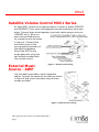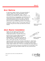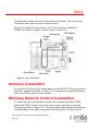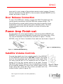
1
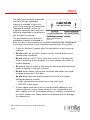
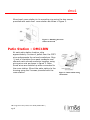
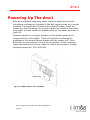
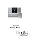
dmc1
dmc1 Finish-Out
Instructions
2861 Congressman Lane | Dallas, Texas 75220 | 800.877.6631 | www.mssystems.com
Page 1
dmc1
Introduction
Designed for installation in new home, the dmc1 is a whole-house
music communications system. It is designed to provide years of
enjoyment and service to the homeowner.
M&S audio products are backed with more than 50 years of experience
in the design and manufacture of precision acoustical equipment for
the home. To ensure that the homeowners receives the high-quality
music and voice reproduction that the system is designed to deliver, it
is important that each step of the installation be done carefully. In the
event you need troubleshooting assistance, please call our technical
staff at 1-800-366-9422.
Prior to installing the dmc1 system, read and observe the Important
Safety Instructions on page 2.
Our web address is www.mssystems.com.
2861 Congressman Lane | Dallas, Texas 75220 | 800.877.6631 | www.mssystems.com
Page 2
dmc1
Important Safety
Instructions
READ ALL INSTRUCTIONS CAREFULLY BEFORE
INSTALLING OR USING THE DMC1 SYSTEM
FOR CONTINUED PROTECTION AGAINST RISK OF FIRE
REPLACE THE FUSE IN THE POWER SWITCH MODULE ONLY
WITH SAME TYPE 6 AMP, 120 VOLT FUSE.
THE dmc1 MUST BE INSTALLED BY A M&S SYSTEMS DEALER OR
INSTALLERS, AND MUST CONFORM TO ALL LOCAL BUILDING
AND ELECTRICAL CODES.
Warning: always follow these safety instructions.
Retain these instructions for future system reference.
• Adhere to all warnings on the dmc1 and in these instructions.
Follow all operating and installation instructions.
•
CAUTION: These installation and servicing instructions are for use
by qualified personnel only. To reduce the risk of electric shock, do
not perform any servicing other than that contained in the
operating instructions unless you are qualified to do so.
•
DO NOT attempt to service the dmc1 yourself as opening or
removing covers may expose you to dangerous voltage or other
hazards. Refer all servicing to qualified service personnel.
2861 Congressman Lane | Dallas, Texas 75220 | 800.877.6631 | www.mssystems.com
Page 3
dmc1
The lightning flash with arrowhead
symbol within an equilateral
triangle is intended to alert the
user to the presence of uninsulated
“dangerous voltage” within the
product’s enclosure that may be of
sufficient magnitude to constitute a
risk of shock to persons.
The exclamation point within an
equilateral triangle is intended to
alert the user to the presence of important operating and maintenance
(servicing) instructions in the literature accompanying the product.
•
Finish out the dmc1 system after the application of wall covering
material.
•
Do not power up the dmc1 master until all remote stations and
speakers are connected.
•
Do not connect a CAT-5 wire if you are unsure of it terminating
point. Connecting a door speaker to a room station may result in
system damage.
•
Do ensure that all rough-in instructions have been followed before
power is applied to the dmc1 system.
•
Do not splice cables. Splices are unreliable and defeat the signal
isolation properties of the cable.
•
Do not attach devices unauthorized for use with this system.
Authorized devices include:
• Audio components connected via a line level input
• DMC1CD 6-disc player
•
If extra cables have been run for future speaker additions, care
must be taken to ensure these cables are not connected to the
dmc1 master unit. Un-terminated cables (no station) connected to
the dmc1 master may cause electronic feedback that will damage
the master unit.
2861 Congressman Lane | Dallas, Texas 75220 | 800.877.6631 | www.mssystems.com
Page 4
dmc1
•
Do not over-tighten the screws for the remote stations or the
master as the plastic face panels may crack or strip out.
•
Use only M&S Systems certified replacement parts and have them
installed by an M&S Systems dealer or installer. Unauthorized
substitutions can result in fire, electric shock, or other hazards.
•
Upon completion of any service or product repair, have the M&S
Systems dealer or installer conduct a safety check to ensure the
system is in proper operating condition.
•
Use only a damp cloth to clean the dmc1 master and room stations.
Do not use liquid cleaners or aerosol cleaners.
Finish-Out Instructions
The finish-out installation should be made after the application of wall
covering material.
Tools required:
•
#2 Phillips screwdriver
•
Standard flat head screwdriver
•
Wire stripper/cutter
• Level
Installing the Room Station
Collect all the connectors included in the room
station packages and place them in the wall
housing for use later. At each room station
location, strip approximately 4 inches of jacket
from the CAT5 wire and separate the colored
conductors from one another. Strip ½ inch of
insulation from each conductor as shown in figure 1.
Figure 1 - CAT5 wire
Connect each colored conductor to its respective screw terminal. The
screw terminals are marked with the appropriate wire colors. Note:
Some screw terminals have more than one wire connected to them.
2861 Congressman Lane | Dallas, Texas 75220 | 800.877.6631 | www.mssystems.com
Page 5
dmc1
Mount each room station to its mounting ring using the two screws
provided with each dmc1 room station as shown in figure 2.
Figure 2 – Attaching the room
station to the wall
Patio Station – DMC1RW
At each patio station location, strip
approximately 4 inches of jacket from the CAT5
wire and separate the colored conductors. Strip
½ inch of insulation from each conductor and
connect each colored conductor together using
wiring wire nuts as shown in figure 3. Note:
Some wires are doubled up when connected to
the room station. Mount the patio station to the
housing using the 2 screws provided with the
room station.
2861 Congressman Lane | Dallas, Texas 75220 | 800.877.6631 | www.mssystems.com
Page 6
Figure 3 – Patio station wiring
connections
dmc1
Satellite Volume Control MVC1 Series
At each MVC1 location strip approximately 4 inches of jacket (MS4XSC
and MS2SXSC) from wires and separate colored conductors from each
other. Connect drain wires together from both cables using a wire nut
(MS4XSC only). Wire nut
each colored conductor to
its respective wire as shown
in figure 4. Connect blue
and violet wires to the
corresponding terminals of
the satellite speakers.
Mount the MVC1to the
single gang box using the
two screws provided with
the volume control.
External Music
Source - AWP
Figure 4 - Volume control wiring
Use the labels provided to mark respective
cables. Connect the cables to the plate as shown
in figure 5 and mount the plate using the two
screws provided.
to dmc1
Figure 5 - External source wiring
2861 Congressman Lane | Dallas, Texas 75220 | 800.877.6631 | www.mssystems.com
Page 7
dmc1
Door Stations
At each door station location, strip approximately 4
inches of jacket from wire and separate colored
conductors from one another. Strip ½ inch of
insulation from conductors as shown in figure 1. Cut
each shield drain wire at jacket to prevent them from
touching each other (MS4DCXSC only). Terminate
yellow and orange wires to the screw terminals on
the bell button (if equipped). Connect the red and
black wires to the red ban black wires on the speaker
respectively. Refer to figure 6. Mount door station to
housing using the two screws provided with the door
station.
Figure 6 - Door station
connections
dmc1 Master Installation
Gather all room station and door station
cables and cut cable ends to the same
length approximately 12 inches from entry
point into wall housing. Make sure that all
cables remain properly labeled. Strip
approximately 2” of insulation from each of
Figure 7 - Connector
wiring diagram
the CAT5 cables. Untwist the individual wire
pairs. Insert each wire pair into the correct
connector location and close connector (see figure 7). Insert each
cable connector into its proper location on the dmc1 master. Note:
Verify that the outdoor patio speaker is connected into the Patios
station cables location only. If you are connecting two patio speakers,
use the screw terminal connectors provided with the dmc1RW for the
patio. Connect both patio stations cables into one screw terminal
connector.
2861 Congressman Lane | Dallas, Texas 75220 | 800.877.6631 | www.mssystems.com
Page 8
dmc1
Important: Verify all cable run locations prior to connecting if they
were not labeled at rough-in. Incorrectly connecting cables to the
master, room stations or door stations may result in system damage.
Install the optional chime module MC3 or
MC8 in the wall housing by pressing the
chime module over the 4 plastic
standoffs attached to the wall housing as
shown in figure 8. Refer to the
instructions shipped with the chime
module.
Suspend the master unit from the
Figure 8 - Chime module
wall housing by looping the third
installation
hand wire (thick green wire) over
the hook at the top of the housing. Be
careful not to damage the wall surface. See figure 9.
If the dmc1 system has more than 9
room stations, some room selector
switches will control two room stations.
Do not exceed more than 15 total
speakers on the system. This limitation
does not include remote controls,
volume controls, speakers connected
to the optional stereo power amp, of
door stations. The station location can
be noted on the inside of the front
access panel on the left side of the
dmc1 master.
Figure 9 - Third hand assembly
Connect the red and black wires of
the door station cables
(MS4DCX/MS4DCXSC) to the red and black door speaker terminals on
the dmc1 master as shown in figure 10. Insulate the bare wires using
some of the jacket material to prevent shorting to the circuit board.
Connect this wire to terminal labeled shield. Connect all orange wires
from the door stations to the common terminal on the MC3 or MC8.
2861 Congressman Lane | Dallas, Texas 75220 | 800.877.6631 | www.mssystems.com
Page 9
dmc1
Connect each yellow wire to a note selection terminal. (Do not connect
more than one yellow wire per note terminal.)
Plug in the modular chime plug to the 4 pin connector labeled as
CHIME on the dmc1 master unit as shown in figure 10.
Figure 10 - dmc1 connections
Antenna Connection
Connect the FM dipole twin lead antenna to the FM 300 Ohm terminals on
the dmc1 master as shown in figure 10. Connect the orange AM antenna
wire to the AM terminal on the master.
Wireless Remote Control Connection
To install the optional wireless remote control receiver module MCRC,
attach the MCRC module using the Velcro strips provided to the wall
housing as shown in figure 10. Place the white antenna lead through the
hole provided in the wall housing into the wall cavity. Failure to do so
2861 Congressman Lane | Dallas, Texas 75220 | 800.877.6631 | www.mssystems.com
Page 10
dmc1
may result in poor range of the wireless remote control system. Connect
the wire harness from the MCRC to the connector labeled REMOTE on the
master as shown in figure 10.
Door Release Connection
To use of the DRW door release, connect the VM127X cables from the
remote power transformer and the DRW door release striker. The
24volt/4amp dry contact switch closure may also be used for home
automation or security panel panic alarm interface. Note: The door
release operation may only be used for one type of function per
application.
Power Amp Finish-out
At each cable end, strip approximately 4 Inches of jacket (MS5XSC and
MS2SXSC) from wires and separate colored wires from each other. Strip
1/2 Inch of insulation from each wire as shown in figure 1. On the
MS7XSC, strip 1/4 Inch of insulation from each wire as shown in figure 2.
Figure 12 – MS7XSC Wiring
Figure 11 – MS5XSC/MS2SXSCWiring
Satellite Volume Controls
Connect the shield wire from outside shield of the MS5XSC
to the MS2SXSC shield wires. DO NOT connect the shield
wire for the brown/gray pair at this end of the cable! Wire
nut each colored wire to its respective wire as shown in
figures 13-14 for the volume control to be used. Connect
the BLUE and VIOLET wires to the corresponding terminals
of the satellite speaker(s). Mount the volume control to the
single gang box using the two screws provided with the
volume control (refer to figure 15).
2861 Congressman Lane | Dallas, Texas 75220 | 800.877.6631 | www.mssystems.com
Page 11
Figure 15 – Volume
control mounting
dmc1
Figure 13 – Stereo
wiring connections
Figure 14 – Mono
wiring connections
Satellite Speakers
At each speaker location, strip approximately 4 Inches of jacket from the
MS2SXSC cables and separate the colored wires from each other. Strip
1/2 Inch of insulation from each wire. Connect the
MS2SXSC cable to the speaker as shown in figure 8.
NOTE: The bare drain wire from the cable is not
connected and should be cut off. On speakers
equipped with RED and BLACK terminals, connect the
BLUE wire to the BLACK terminal and the VIOLET
wire to the RED terminal.
Figure 16 – Speaker
Amplifier Mounting
connections
The amplifier module will install on a single vertical stud previously
marked during rough-in. The vertical height of the
amplifier will allow complete coverage over the wall
openings for the remote volume controls and control
panel wiring. Mark the location of the top mounting
keyhole and bottom mounting holes. With the amplifier
removed verify the location of the vertical stud by
installing the enclosed mounting screws at the marked
locations. Once the location of the stud has
Figure 17 – Amplifier mounting
been verified, remove the screws. Remove
the cover from the amplifier. While positioning the amplifier (with cover
removed) into position, bring the volume control and preamp cabling
through the holes provided. Secure the amplifier to the wall in the
2861 Congressman Lane | Dallas, Texas 75220 | 800.877.6631 | www.mssystems.com
Page 12
dmc1
marked locations with the screws provided as shown in figure 17. FAILURE
TO PROPERLY MOUNT THE AMPLIFIER MAY LEAD TO AMPLIFIER DAMAGE AND/OR
VOLUME CONTROL/PREAMP WIRING DAMAGE.
dmc1 Connection
Locate the MS7X5SC cable from the dmc1 master. Connect
each of the 7 colored wires and shield drain wire from the
MS7XSC cable to the 8 pin terminal block as shown in
figure 18. Plug the 8 pin
connector into the jack labeled
PREAMP INTERCONNECT. Locate
the MS7X5SC cable from the
second power amplifier
(MC960PA), if used. Connect
each of the 7 colored wires and
Figure 18 – Wiring
shield drain wire from the
diagram
MS7XSC cable to the 8 pin
terminal block as shown in figure 18. Plug the
from
8 pin connector into the jack labeled TO
dmc1
SECOND AMP.
dmc1
Gather all volume control cables (MS5XSC).
Pigtail all shield drain wires (bare) from the
Figure 19 – Wiring
MS5XSC cables to the SHIELD terminal on the
connections
remote amplifier. Then connect each of the colorcoded wires to its respective terminals as shown in Figure 19.
2861 Congressman Lane | Dallas, Texas 75220 | 800.877.6631 | www.mssystems.com
Page 13
dmc1
Stereo/Mono Configuration
Each MC960PA remote amplifier is equipped with a stereo/mono select
jumper. All MC960PA amplifiers are shipped
from the factory with this jumper in the STEREO
position. If an amplifier is required to drive more
than 10 monaural speakers, this jumper must
be set to the MONO position (refer to figure 20).
Setting the jumper to the MONO position will
cause monaural output to all speakers whether
they are connected via stereo controls or mono
controls. The jumper setting of one MC960PA
amplifier has no effect on other MC960PA
amplifiers.
Figure 20 – Jumper connections
Other Sources
Plug in the RCA phono plugs to the jacks as marked for the source
equipment. Figure 21 shows a typical installation using the AWP/AWPRX
audio wall plate installation kit.
to dmc1
Figure 21 – AWP audio plate
connections
2861 Congressman Lane | Dallas, Texas 75220 | 800.877.6631 | www.mssystems.com
Page 14
dmc1
Powering Up The dmc1
After all connections have been made, insert the power plug into the
transformer and secure the master to the wall housing using the 2 screws
provided. If using the dmc1F frame with a dmc1CD player, install the
master unit over the frame. Do not over tighten the screws as the plastic
may distort or crack. Install the speaker panel on the master as shown in
figure 22.
Please be careful to only apply pressure on the speaker panel at the
corners and not in the middle. Check all functions by following the
guidelines in the Owners Manual shipped with the master unit. If any
difficulties are encountered, recheck all connections. If after reviewing
these instructions and you are unable to resolve any problems, contact
technical support at 1-800-366-9422.
Figure 22 - DMC1 speaker cover installation
2861 Congressman Lane | Dallas, Texas 75220 | 800.877.6631 | www.mssystems.com
Page 15
dmc1
M&S Systems 2-Year Warranty
M&S Systems warrants its products to be free of defects for 2 years. Except for
the AirVac Gold power units. The warranty period begins on either (a) the date
of purchase or installation date of this product or (b) the date of closing on a
new residence in which this product was originally installed. The warranty
extends to the original user of the product and to each subsequent owner of the
product during the term of the warranty. M&S will repair or replace, at its
option, parts and materials at no charge. Parts supplied under this warranty may
be new or rebuilt at the option of M&S Systems.
If during the warranty period the product appears to have a defect, please call
our toll free service number (800-366-9422) prior to dismantling. Dismantling
the product prior to calling our service number may void the warranty. Before
returning any product to M&S Systems, obtain a Return Authorization Number
(RAN) from our service department. M&S Systems will return the repaired
product freight prepaid within the continental United States. ANY PRODUCT
RETURNED TO M&S SYSTEMS WITHOUT A RAN NUMBER WILL BE REFUSED.
This limited warranty is in lieu of any other warranties, express or implied,
including any implied warranty of merchantability or fitness for a particular
purpose or otherwise, and of any other obligations or liability on the seller’s
part. This limited warranty does not cover damage caused by improper
installation, acts of God, criminal acts, the violation of applicable building or
electrical codes or the use of non-M&S wire, cable (excluding CAT5 and RG-6) or
wall housings.
Under no circumstances shall M&S Systems be liable for consequential,
incidental or special damages arising in connection with use, or inability to use
this product. In no event shall M&S Systems liability hereunder exceed the cost
of the product covered hereby. No person is authorized to assume for us or
obligate us for any other liability in connection with the sale of this product.
Some states do not allow the exclusion or limitation of consequential, incidental
or special damages, so the above limitation or exclusion may not apply to you.
This limited warranty gives you specific legal rights, and you may also have
other rights, which vary from state to state.
116002
2861 Congressman Lane | Dallas, Texas 75220 | 800.877.6631 | www.mssystems.com
Page 16