1
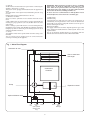
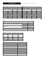
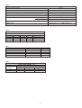
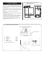
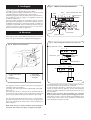
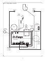
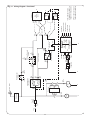
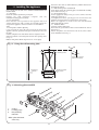
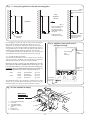
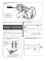
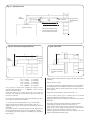
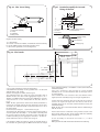
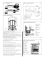
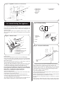
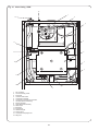
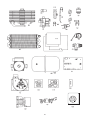
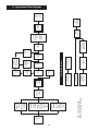
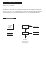
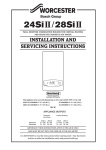
Bosch Group
15SBi / 24SBi
WALL MOUNTED BOILERS FOR CENTRAL HEATING
and Indirect supply of domestic hot water
INSTALLATION AND
SERVICING INSTRUCTIONS
24SBi
This appliance is for use with Natural Gas or LPG (Cat II 2H3P).
15SBi GC NUMBER 41 311 43 (N.G.) 24SBi GC NUMBER 41 311 44 (N.G.)
15SBi GC NUMBER 41 311 45 (L.P.G.) 24SBi GC NUMBER 41 311 46 (L.P.G.)
APPLIANCE OUTPUTS
Natural Gas
LPG (Propane)
24SBi
Minimum 15.0 kW
Maximum 24.0 kW
15.0 kW
24.0 kW
15SBi
Minimum 6.0 kW
Maximum 15.0 kW
6.0 kW
15.0 kW
IMPORTANT: THESE INSTRUCTIONS APPLY IN THE UK ONLY
AND MUST BE LEFT WITH THE USER OR AT THE GAS METER
Read the instructions before starting work - they have been written to make
the installation easier and prevent hold-ups.
Contents
1. Installation Regulations . . . . . . . . . . . . . . . . . . . . . . . . . . . Page 2
2. Introduction . . . . . . . . . . . . . . . . . . . . . . . . . . . . . . . . . . . . . Page 2
3. Technical Data . . . . . . . . . . . . . . . . . . . . . . . . . . . . . . . . . . . Page 4
4. Siting the Appliance . . . . . . . . . . . . . . . . . . . . . . . . . . . . . . Page 6
5. Flue Terminal Positions . . . . . . . . . . . . . . . . . . . . . . . . . . . . Page 7
6. Air Supply . . . . . . . . . . . . . . . . . . . . . . . . . . . . . . . . . . . . . . . Page 7
7. Sealed System . . . . . . . . . . . . . . . . . . . . . . . . . . . . . . . . . . . Page 8
8. Domestic Hot Water . . . . . . . . . . . . . . . . . . . . . . . . . . . . . . Page 8
9. Gas Supply . . . . . . . . . . . . . . . . . . . . . . . . . . . . . . . . . . . . . . Page 10
.........................................................
10. Electrical . . . . . . . . . . . . . . . . . . . . . . . . . . . . . . . . . . . . . . . Page 10
11. Installing the Appliance . . . . . . . . . . . . . . . . . . . . . . . . . . Page 13
12. Commissioning the Appliance . . . . . . . . . . . . . . . . . . . . Page 19
13. Instructions to the User . . . . . . . . . . . . . . . . . . . . . . . . . . Page 21
14. Inspection and Service . . . . . . . . . . . . . . . . . . . . . . . . . . . Page 21
15. Replacement of Parts . . . . . . . . . . . . . . . . . . . . . . . . . . . . Page 21
16. Component Parts List. . . . . . . . . . . . . . . . . . . . . . . . . . . . Page 28
17. Operational Flow Diagrams. . . . . . . . . . . . . . . . . . . . . . . Page 29
18. Fault Finding . . . . . . . . . . . . . . . . . . . . . . . . . . . . . . . . . . . Page 30
1. Installation Regulations
2. Introduction
1.1 Gas Safety (Installation & Use) Regulations 1998.
It is the law that all gas appliances are installed by a competent
person in accordance with the above regulations. Failure to
install appliances correctly could lead to prosecution. It is in
your interest, and that of safety, to ensure compliance with the
law.
1.2 The manufacturers notes must not be taken, in any way, as
overriding statutory obligations.
1.3 The compliance with a British Standard or European Norm
does not, in itself, confer immunity from legal obligations.
1.4 The installation of the appliance must be in accordance with
the relevant requirements of the Gas Safety Regulations, current
IEE Regulations, Building Regulations, Building Standards
(Scotland) and local water bye-laws.
1.5 The installation should follow the recommendations of the
following British Standards unless otherwise indicated and to
any other relevant standards.
BS5440:1 - Flues and ventilation for gas appliances: Flues
BS5440:2 - Flues and ventilation for gas appliances: Air supply.
BS5449 - Central heating for domestic premises.
BS5482 - Domestic propane gas burning installations.
BS5546:1 - Installation of gas hot water supplies.
BS6700 - Domestic water supply (when relevant).
BS6798 - Installation of gas fired hot water boilers.
BS6891 - Low pressure gas pipework installations up to 28mm
(R1).
BS7593 - Water treatment.
BS7671 - Requirements for electrical installations.
1.6 The appliance and/or components must conform, where
applicable, to all relevant Directives.
1.7 In accordance with COSSH the appliance does not contain
any substances which are harmful to health.
1.8 Product Liability regulations indicate that, in certain
circumstances, the installer can be held responsible, not only for
mistakes on his part but also for damage resulting from the use
of faulty materials. We advise that to avoid any risk, only
quality approved branded fittings are used.
1.9 LPG Installation. The appliance shall not be installed in a
room or internal space below ground level when it is intended for
use with LPG. This does not preclude the installation into rooms
which are basements with respect to one side of the building but
open to the ground on the opposite side.
1.10 These instructions cover, as far as possible, the foreseeable
situations which may arise. Contact Worcester Heat Systems
Technical Department, Telephone: 0990 266241, for advice on
specific installations.
2.1 General Information
The appliance is set to give the mid-range output of 19.5kW
[24SBi] or 10.8kW [15SBi].
Kits are available to convert the appliance from Natural Gas to
Propane operation and vice versa.
2.2 Electrical Supply
230V - 50Hz. Load 180 watts. External fuse 5A, Internal fuse
F1 - 4A.
2.3 Gas supply
The 24SBi appliance requires a maximum of 2.86 m 3/h of
natural gas (G20) or 1.1 m3/h of propane (G31).
The 15SBi appliance requires a maximum of 1.78 m 3/h of
natural gas (G20) or 0.68 m3/h of propane (G31).
The installation and the connection of the gas supply to the
appliance must be in accordance with BS6891.
The meter or regulator should deliver a dynamic pressure of 20
mbar (G20) or 37mbar (G31) at the appliance, which is
equivalent to about 19 mbar or 36 mbar at the gas valve inlet
pressure test point.
Total length of gas supply pipe Pipe size
(metres)
(Ømm)
3
6
9
12
Propane
Gas
1.5
–
–
–
15
Discharge
8.0
5.2
4.2
3.6
22
Rate
Gas Discharge
15.9
8.8
8.5
7.2
28
Rate 3
Natural Gas
3 (m /hr)
(m /hr)
8.7
5.8
4.6
–
22
18.0
12.0
9.4
–
28
2.4 Installation
The appliance is suitable for indoor installation and for use with
a sealed system only and includes a built in filling loop.
If the appliance is fitted in a cupboard or a compartment is built
around it after installation, then the structure must conform with
the requirements of BS6798. However, because of the low casing
losses, there is no need for cooling ventilation openings in the
compartment. The spaces specified for servicing must be
maintained. Refer to Section 6.
An optional wall frame is available to create space for the service
pipes to pass at the back of the appliance.
2.5 Flue
The flue can be to the right, left or rear. A vertical flue system is
available.
An internal flue fitting kit is available. Fitting instructions are
given in Section 11.9.
2.6 Controls
A control knob adjusts the CH temperature and switching.
A facia mounted mechanical clock is available.
Only mains voltage external controls can be used.
A plug- in mid-position diverter valve is available as an optional
extra.
2
2.7 System
All dirt must be flushed from the system before connecting the
appliance. Refer to Fig. 5,6 and 7.
The system can be pre-piped and flushed before the appliance is
fitted.
The connections in the system must withstand a pressure of up
to 3 bar.
Radiator valves must conform to BS2767:10:1977.
2.8 Domestic Hot Water
Single feed direct cylinders are not suitable and must not be
used.
A HW cylinder must be of the indirect coil type and suitable for
working at a gauge pressure of, at least, 0.35bar above the relief
valve setting.
Where a storage system will not have a vent to atmosphere the
installation must comply with Building Regulations and Water
Company bye-laws. If connecting to an existing system the local
authority should be informed.
2.9 Safety
The appliance must not be operated with the inner casing cover
removed.
The gas and electricity supplies must be turned off before
servicing or working on the appliance.
IMPORTANT: Where back-flow prevention devices, including
water meters, are fitted the expansion of hot water into cold
water main can be prevented. This can result in a pressure
build-up that may cause damage to the boiler and household
devices such as showers, washing machines etc.
In these cases we recommend that a mini-expansion vessel
be fitted adjacent to the boiler in the cold water pipe.
2.10 Operation
Central Heating
A demand for heat will ignite the burner. The temperature is
controlled by the integral sensor. At the end of the demand the
burner will go out and the pump will continue to run for up to 3
minutes to dissipate the heat.
Domestic Hot Water:
The supply of domestic hot water depends upon the type of hot
water equipment installed and the control system. Refer to the
separate leaflet.
The use of unvented cylinders must be in accordance with the
manufacturers instructions relevant to British Standards
Fig. 1. Water flow diagram.
Automatic air vent
Gas to water heat
exchanger
Combustion
Chamber
Pump
Expansion vessel
By-pass
Optional diverter valve
C.H.
flow
Return
Cold in
Cylinder
flow
(with optional
diverter valve
only)
3
Relief
valve
discharge
3. Technical Data
Table 1.
The data plate is fixed to the inner casing cover.
15SBi
Table 1.
24SBi
NOMINAL BOILER RATINGS (10 Minutes After Lighting)
BOILER ADJUSTED FOR G20 (Natural Gas)
BURNER
OUTPUT
INPUT (Net)
GAS RATE
PRESSURE
kW
kW
m bar.
m3/h
6
6.93
1.6
0.73
10.8
12
6.4
1.27
15
16.65
12
1.76
NOMINAL BOILER RATINGS (10 Minutes After Lighting)
BOILER ADJUSTED FOR G20 (Natural Gas)
BURNER
OUTPUT
INPUT (Net)
GAS RATE
PRESSURE
kW
kW
m bar.
m3/h
15
17.5
4.5
1.85
19.5
22.1
8
2.34
24
27
12.5
2.86
BOILER ADJUSTED FOR G31 (Propane)
6.93
4.3
12
13.9
BOILER ADJUSTED FOR G31 (Propane)
17.5
13.5
22.1
22.5
6
10.8
15
16.65
28.6
0.28
0.49
15
19.5
0.68
24
Natural Gas: Net Input = Gross Input x 0.901
27
35.5
LPG (Propane): Net Input = Gross Input x 0.922
Table 2.
FLUE DETAILS
HORIZONTAL FLUE
mm
WALL HOLE DIAMETER
STANDARD FLUE
EXTENDED FLUE
EXTERNAL FIX
110
INTERNAL FIX
150
MINIMUM LENGTH
100
MAXIMUM LENGTH
725
MAXIMUM LENGTH
4000
FLUE ASSEMBLY DIAMETER
100
Table 3
MAXIMUM AVAILABLE PUMP HEAD
BOILER OUTPUT
kW
HEAD
Metres
MIN. FLOW RATE
L/min.
FLOW/RETURN
DIFFERENTIAL
°C
6.0
5.7
7.8
11
15.0
3.8
19.5
11
24.0
2
27
12.7
Table 4
MECHANICAL SPECIFICATIONS
CENTRAL HEATING FLOW - COMPRESSION
22mm
RETURN - COMPRESSION
22mm
COLD WATER INLET - COMPRESSION
15mm
CYLINDER FLOW - COMPRESSION
22mm
GAS INLET
Rp 3⁄4
RELIEF VALVE DISCHARGE - COMPRESSION
15mm
CASING HEIGHT
850mm
CASING WIDTH
450mm
CASING DEPTH
365mm
WEIGHT - LIFT
15SBi 35kg
24SBi 37kg
WEIGHT - PACKAGED
15SBi 42kg
24SBi 44kg
4
0.72
0.9
1.1
Table 5
PERFORMANCE SPECIFICATIONS
PRIMARY WATER CAPACITY
2.0 litres
MAXIMUM MAINS INLET PRESSURE
10 bar
MAXIMUM CENTRAL HEATING FLOW TEMPERATURE
85°C (nom)
MAXIMUM CENTRAL HEATING SYSTEM SET PRESSURE
2.5 bar
MINIMUM CENTRAL HEATING SYSTEM SET PRESSURE
0.5 bar
OUTPUT TO CENTRAL HEATING
NATURAL GAS (G20)
15SBi 6.0 - 15.0kw
24SBi 15.0 - 24.0kw
LPG - PROPANE (G31)
15SBi 6.0 - 15.0kw
24SBi 15.0 - 24.0kw
NOx CLASSIFICATION FOR BOTH 15 & 24SBi
Class 2
SEDBUK Rating
15SBi - Band D - 79.1% 24SBi - Band D - 78.3%
Table 6
GAS SUPPLY SYSTEM - BASED ON NG (G20)
TOTAL LENGTH OF GAS SUPPLY PIPE (COPPER) metres
3
6
9
12
GAS DISCHARGE RATE - PRESSURE DROP mbar. m3/h PIPE DIAMETER mm
8.7
5.8
4.6
3.9
22
18.0
12.0
9.4
8.0
28
Table 7
CLEARANCES
(mm)
INSTALLATION
ABOVE APPLIANCE FLUE ELBOW
30
IN FRONT OF APPLIANCE
600
BENEATH APPLIANCE
200
RIGHT AND LEFT HAND SIDE
10
SERVICE
30
600
200
10
Refer to Section 6.
Table 8
INITIAL
PRESSURE bar
1.0
1.5
SYSTEM CAPACITY
TOTAL SYSTEM VOLUME litres
INITIAL CHARGE PRESSURE bar
0.5
1.0
1.5
72
92
N/A
39
53
64
5
Fig. 2. Appliance casing dimensions and
required clearances.
4. Siting The Appliance
The appliance may be installed in any room subject to the
requirements of the current IEE regulations and, in Scotland, the
relevant electrical provisions of the Building Regulations with
respect to the installation of appliances in rooms containing
baths or showers.
If the appliance is installed in a room containing a bath or
shower, any switch or appliance control using mains electricity
must NOT be able to be touched by a person using the bath or
shower.
The appliance is NOT suitable for external installation.
The wall must be able to support the weight of the appliance.
Refer to Table 4.
The specified clearances must be available for installation and
servicing. Refer to Table 7 and Fig.2.
The appliance can be installed in a cupboard/compartment to
be used for airing clothes providing that the requirements of
BS6798 and BS5440/2 are followed. Refer to Section 2.4.
The clearance between the front of the appliance and the
cupboard/compartment door should be not less than 250mm.
LPG Installation. Refer to Section 1.10.
30mm*
150mm
Front view
365mm
600mm*
850mm
225mm
Side view
450mm
200mm*
10mm*
10mm*
* Space required for installation and servicing
Fig. 3. Appliance pipework connections
Screw driver required to operate Valves.
Valves shown closed.
F
Rear of appliance
A
B
C
D
E
View on underside of appliance showing
connections
A
B
C
D
E
F
CH Flow
Cylinder Flow*
Cold In
Gas Inlet
Return
Safety Discharge
=
=
=
=
=
=
62.5
127.5
192.5
257.5
322.5
382.5
(F)
195
*Use with optional diverter valve
61
A
B
C
91
D
E
F
6
(A, B, C, D, and E)
5. Flue terminal positions
6. Air Supply
The flue system must be installed following the requirements of
BS5440:1.
The standard flue kit length is 425 - 725mm. Extension kits for
flues up to 4m are available.
The terminal must not cause an obstruction nor the combustion
products a nuisance.
If the terminal is within 1m of a plastic or painted gutter or
within 500mm of painted eaves then an aluminium shield at
least 750mm long should be fitted to the underside of the gutter
or painted surface.
If the terminal is less than 2m above a surface to which people
have access then a guard must be fitted. The guard must be
evenly spaced about the terminal and fixed with plated screws.
A guard Type K2 can be obtained from Tower Flue Components,
Vale Rise, Tonbridge, TN9 1TB.
It is essential that products of combustion cannot re-enter the
building. Refer to Fig 4.
A separate vent for combustion air is not required.
If the appliance is in a cupboard or compartment it is not
necessary to have additional ventilation for the boiler
providing that the following clearances are provided:
Above the flue turret
30mm
In front*
250 mm
Below
200mm
Right-hand side
75 mm
Left-hand side
75mm
* Clearance to a removable panel i.e. door.
If the appliance is installed in a cupboard or compartment that
does not allow these clearances then permanent air vents are
required in the compartment, one at a high level and one at a
low level. Both high and low level air vents must communicate
with the same room or must both be on the same wall to the
outside air. The minimum requirements are:
Model
Position of vent
24SBi
15SBi
Air from room
Air from outside
High
2
315cm
158cm2
Low
315cm2
158cm2
High
315cm2
158cm2
Low
315cm2
158cm2
Fig. 4. Siting of the flue terminal.
A
L
G
B,C
K
L
D
K
F
F
HI
A
F
J
TERMINAL POSITION
A– directly below an openable window or
other opening e.g. air brick.
B– Below gutters, soil pipes or drain pipes.
C– Below eaves.
D– Below balconies or car port roof.
E– From vertical drain pipes and soil pipes.
F– From internal or external corners.
G– Above ground, roof or balcony level.
H– From a surface facing a terminal.
E
G
M
MIN. DISTANCE
TERMINAL POSITION
I– From a terminal facing a terminal
J– From an opening in a car port (e.g. door
window) into dwelling.
K– Vertically from a terminal on the same
wall.
L– Horizontally from a terminal on the same
wall.
M– From door, window or air vent (achieve
where possible).
300mm
75mm
25mm
25mm
25mm
25mm
300mm
600mm
7
MIN. DISTANCE
1200mm
1200mm
1500mm
300mm
300mm
expansion vessel must be fitted as near to the appliance as
possible in the return pipe.
A filling loop is fitted to the appliance. Refer to Fig 8.
The system and the appliance must be properly vented.
Repeated venting loses water from the system and usually
indicates that there is a leak.
An adjustable by-pass is fitted to the appliance. Refer to Fig 9.
The pump is set at maximum and must be adjusted to suit the
system load
7. Sealed System
7. Sealed System
The system must comply with requirements of BS6798 and
BS5449.
The appliance must not be operated without the system being
full of water and correctly pressurised.
The pressure relief valve will operate at 3 bar. The discharge pipe
must be directed away from any electric's or from where it might
be hazard.
All connections in the system must withstand a pressure of up to
3 bar.
The expansion vessel, to BS4814, has a capacity of 10 litres
charged to 0.5 bar, which is suitable for a static head of 5 metres.
A schraeder type valve allows the pressure to be increased if the
static head is greater than 5 metres. Refer to BS 7074:1, BS5449
and Table 9 for a guide to the available system capacity. If the
expansion vessel fails then it must be replaced with the
designated spare part.
The maximum system design pressure is 1.5 bar. If the pressure
is above 2.6 bar when at maximum temperature then another
8. Domestic Hot Water
It is NOT suitable for direct water supply.
Do not connect to a direct cylinder.
The SBi can be connected to any indirect cylinder, i.e unvented or
thermal store, all the benefits of a "dry loft" and mains pressure
hot water can be realised. Refer to a separate leaflet or contact
Worcester Heat Systems Technical Helpline. 0990 266241.
Fig. 5. System layout if using built - in diverter valve.
LV
RV
For Details of
the wiring
requirements
for the system
controls,
please refer to
the SBi System
Wiring Guide
and the
Instructions
supplied with
the Built-in
Mid-Position
Valve.
INDIRECT
CYLINDER
LV
RV
Cylinder Return
Note:
A drain cock
should be fitted
at the lowest
point of the
heating circuit
and beneath
the appliance
IMPORTANT
APPLIANCE
RV
LV
Heating Return
LV
Heating Flow
RV
Radiator Valve - Flow
RV
Lockshield Valve - Return LV
Refer to fig.1.
Appliance
Water
Flow
Diagram
Safety Discharge
Hot Water Flow
Mains Cold Water
BS
Stop Valve Fixed Cylinder Type
Fig. 6. System layout if using external diverter valve.
LV
RV
APPLIANCE
RV
Radiator Valve - Flow
RV
Lockshield Valve - Return LV
Heating Return
LV
Refer to fig.1.
Appliance
Water
Flow
Diagram
Safety Discharge
Diverter
Valve
Mains Cold Water
BS
Stop Valve Fixed Cylinder Type
8
Hot Water Flow
Cylinder Return
RV
LV
RV
For Details of
the wiring
requirements
for the system
controls,
please refer to
the SBi system
wiring guide.
INDIRECT
CYLINDER
LV
Heating Flow
Note:
A drain cock
should be fitted
at the lowest
point of the
heating circuit
and beneath
the appliance
IMPORTANT
Fig. 7. System layout if using twin zone valves (S) plan.
LV
RV
For Details of
the wiring
requirements
for the system
controls,
please refer to
the SBi system
wiring guide.
INDIRECT
CYLINDER
LV
RV
APPLIANCE
RV
LV
Radiator Valve - Flow
RV
Lockshield Valve - Return LV
Heating Flow
RV
Fig. 8. Filling Loop.
Heating Return
LV
CH
Zone
Valve
Refer to fig.1.
Appliance
Water
Flow
Diagram
Safety Discharge
Hot Water Flow
Cylinder Return
Note:
A drain cock
should be fitted
at the lowest
point of the
heating circuit
and beneath
the appliance
IMPORTANT
DHW Zone Valve
Mains Cold Water
BS
Stop Valve Fixed Cylinder Type
Fig. 8a. Filling Key inserted for filling.
Filling Loop
Filling Key
NOTE:
Always remove
the filling key
after filling
Filling Knob
Fig. 9. Central heating by-pass adjustment
Central Heating
System By-Pass
Adjustment Screw
Use Flat Bladed
Screwdriver to
make adjustment.
9
9. Gas Supply
Fig.11 . Mains electricity connections.
The 24SBi appliance requires a maximum of 2.86m3/h of natural
gas (G20) or 1.1m3/h of propane (G31). Refer to Table 1.
The 15SBi appliance requires a maximum of 1.76m3/h of natural
gas (G20) or 0.68m3/h of propane (G31). Refer to Table 1.
A natural gas appliance must be connected to a governed meter.
The installation of the gas supply to the appliance must be in
accordance with BS6891.
The meter and the pipework to the appliance must be checked,
preferably by the gas supplier, to ensure that a dynamic pressure
of 20mbar for natural gas or 37mbar for propane is available at
the appliance [equivalent to about 18mbar or 35mbar at the gas
valve inlet pressure connection] and that the gas flow is
adequate for all the installed gas appliances.
Bottom Left Hand Side - Facia
Earth
230V
L
ST12
N
Ls
Lr
N
External Controls
Green
/yello
w
Blue
n
ow
Br
Brown
10. Electrical
Blue
Green/yellow
Strain relief clamp
Mains supply: 230V ( 50 Hz 180watts. External fuse 5A. Internal
fuse F1-4A. Spare internal fuse is supplied with the appliance.
Fig 12 - Mains Voltage External Controls Connections
Fig 10 - Replacement internal fuse
1
Room Thermostat - 230 Volt
Ls Lr
2
N
X2
Live
Switched Live
Neutral
Remove link
3
Room Thermostat
4
Frost Thermostat - 230 Volt
Ls Lr
FROST
X2
5
1. Control Panel Pivot
Point
2. Fuse -F1
3. Pressure Gauge
N
4. Facia Panel
5. Control Board
Assembly
Frost Thermostat
A room thermostat must be suitable for mains voltage operation.
A mechanical timer, to fit into the facia, is available.
A frost thermostat should be considered where parts of the
system are remote from the appliance. For any frost thermostat
function, the boiler temperature control knob must not be set to
the 'off' position.
NOTE: In some cases these devices should not be connected
at these points. Refer to separate system wiring guide booklet.
Safety Check: If there is an electrical fault after installation check
for fuse failure, short circuits, incorrect polarity of connections,
earth continuity or resistance to earth.
The appliance must be earthed and it must be possible to
completely isolate the appliance.
The mains cable must be 0.75mm2 (24x0.20 mm) to BS6500 Table 15 or 16.
The mains cable must be connected to the terminal marked L
(red or brown lead), N (black or blue lead) and the Earth stud
(green or green/yellow lead) and secured with the cable clamp.
The connection to the mains must be either : A 3A fused threepin plug and unswitched socket outlet (both complying with
BS1363) or a double pole isolator with a contact separation of
3mm in all poles.
NOTE: There must be no other permanent electrical supply to
the system. This ensures the safety of a single fused supply.
10
Fig.13 . Wiring diagram - pictorial.
Fan
Overheat
Cut-off
CH Sensor
Flame
Sense
Electrode
Spark
Electrode
Gas Valve
Mid
Position
Valve
Y Plan
(Optional)
Pump
Cylinder
Thermostat
1
1
X10
Air Flow
Switch
1
X11
X12
Control Board
X4
X3
X1
X2
1
br
br
br
bl
y
br
X5
bl
bl
2 green
2 red
bl - Blue
br - Brown
y - Yellow
g - Green
Facia
Mounted
Timer
(Optional)
X6
2 orange
11
Live
Pin L
X1
Fuse F1
4A Fast
12
Pump
N
X5
101
RY
Top Pin
Electronics
Electronics
Pin 1
X12
Left
Terminal
X2
2
RY
N
Fan
102
RY
X4
Top Pin
Top Pin
X5
Hot water
ON
OFF
Central
Heating
ON
X12
Pin 5
X12
Pin 4
X12
Pin 3
X2
N
Right
Terminal
Frost Thermostat
(if fitted)
Operating Switch
or Programmer
Power ON - Green
Pin 2
X3
Call
X3
Pump
Fan
Spark
Valve
Pin 4 Gas
Pin 3
X3
C
Satisfied
X3
Pin 1
DC
Pin 1
X10
Pin 2
X10
Cylinder Thermostat
X10
Pin 3
Provides CH only signal
X2
Pin Lr
Room Thermostat
(if fitted)
Optional Link
Overheat
Thermostat
X2
Pin LS
X2
Pin N
OS
N
Electronics
Safety
Low
Voltage
Boiler Demand
High
Voltage
Y
Slide switch
X11
Pin 3
X11
Pin 2
X11
Pin 1
Flame Sense
Air Flow Switch
Temperature Sensor
Temperature Control
Reset Button
*
Zone
Valve
DHW
Zone
Valve
CH
S Plan
Mid
Position
Valve
Y Plan
N
N
N
S-Plan valves can only be
fitted outside the appliance
available, as an option, for
fitting within the appliance.
* A Mid-Position Valve is
orange
grey
white
Fig.14 . Wiring diagram - functional
Cut the flue duct hole at 110mm diameter [150mm diameter for
internally fitted flues].
11.4 Wall Mounting Plate and Manifold
Fit the plugs and fix the mounting plate and manifold assembly
to the wall. Refer to Fig 15.
11.5 Gas and Water Pipes
Fix the appropriate fitting to the gas cock to connect the inlet
supply pipe. Refer Fig 16.
It is important that the system pipes are not fixed near the
appliance using clips that put a strain on the connections.
Before the appliance is connected to the wall manifold
thoroughly flush the system.
11.6 Install the Boiler
Lift off the cabinet front panel.
Check that the gas and water valves on the manifold are closed.
Refer to Fig 16.
Remove the plastic cover and fit the seals to the service valves
on the manifold. Refer to Fig 16.
11. Installing The Appliance
Note: READ THIS SECTION FULLY BEFORE COMMENCING THE
INSTALLATION
11.1 Unpacking
Check the contents against the packing list.
Remove the wall mounting template and the
manifold/mounting plate assembly.
11.2 Site Preparation
Check that the correct position for the appliance has been
chosen and that the wall is sound, flat and will support the
weight of the appliance. Refer to Sections 4 & 5 and Tables 4
and 8.
11.3 Fixing Holes and Flue Opening
If it is necessary for any of the pipes to run up the back of the
appliance then the, optional extra, space frame must be fitted to
the wall.
Hold the template to the wall. Check that the template is level.
Mark the position of the fixing holes and the flue opening. Refer
to Fig 15.
Drill the fixing holes 60mm deep for the No. 12 size plugs.
Fig. 15 . Fixing the wall mounting plate.
116
211
Top wall fixing screws
(2)
19
6.5
(230mm if the optional
space frame is fitted)
723
Pre-plumbing
manifold
820
Plumbing manifold
fixing screws
(4)
99
425
Dimensions in mm
Fig. 16 .Mounting plate manifold.
w
Flo
g
n
ti
ea
lH
w*
a
r
nt
Flo
et
e
r
C
Inl
de
r
n
e
i
l
at
Cy
t
sW
n
i
nle
Ma
sI
a
G
e
rg
ha
c
s
Di
lve
a
fV
lie
Re
n
tur
Re
1.
2.
3.
O-Ring
Locating pegs
Pre-plumbing
manifold
* With optional diverter
valve only
1
2
3
13
ing
en
p
eO
Pip
Fig. 17 . Fixing the appliance to the wall mounting plate.
Step. 2
Secure the top with
M6 nuts and washers
(2).
Keep
Appliance
Vertical
Appliance
Step. 1
Rest the appliance on
the pre-plumbing
manifold and push
backwards engaging
the valves.
Step.3
Secure the bottom
with the caps and
washers (3).
Check that all the
O-Rings are in place.
Pre-plumbing
manifold
Lift the appliance against the wall to engage in the top support
plate and lower onto the manifold assembly. Refer to Fig. 17.
Tighten the gas and water connections. Lower the facia and fit a
discharge pipe to the relief valve leading it away from any electric's.
The pipe must not be less than 15mm in diameter and must run
continuously downward outside the appliance. Refer to Fig 47.
If the optional internally fitted diverter valve is to be connected
then full instructions are sent with the valve. Refer to Fig. 20.
Fig.18. Appliance casing and control
equipment fixings.
Side casing
fixing
screws (4)
Inner casing
cover
screws (4)
11.7 Air and Flue Duct Preparation
The method of installation of the flue system may be varied to
suit the actual site conditions. The instructions for connecting
and fixing the ducts must, however, be strictly followed.
Unpack the flue spigot, restrictor ring and clamping rings from the
Flue Spigot Kit in the boiler Installation Pack. Fit the spigot to the
boiler top panel with the four screws provided in the Flue Spigot Kit.
Facia panel
fixing
screws (2)
IMPORTANT Check the maximum flue length and if it is less than 1m
total overall length then fit the restrictor ring as shown in Fig. 21.
24SBi
15SBi
- 75mm
- 75mm
- 74mm
- 79mm
Horizontal flue
Vertical flue
Horizontal flue
Vertical flue
up to 1m
up to 1m
up to 1m
up to 1m
Connections
cover fixing
screws (3)
The standard telescopic flue assembly is suitable for flues from
425mm up to 725mm measured from the centre-line of the
boiler flue outlet to the outer face of the wall. Refer to Fig.22.
24SBi
Fig.19. Flow manifold assembly
6
IMPORTANT
DO NOT REMOVE
THIS CLIP!
1.
2.
3.
4.
5.
6.
Flow manifold assembly
Connector
Clips (Removable)
Assembly mounting
plate
Filling Loop
Protection cap
1
5
3
2
14
4
Fig.20. Mid-position diverter valve
(Optional)
IMPORTANT
5
DO NOT REMOVE
THIS CLIP!
1
1.
2.
3.
4.
5.
6.
7.
Flow manifold assembly
Clips (Removable)
Diverter valve connector plug
Earth connection
Mid-position diverter valve
Valve status indicator
Manual operating switch
4
2
6
3
between 425mm and 725mm.
Fix the flue assembly together using the self-tapping screws
provided. Refer to Fig.22.
If L>725mm then extension duct kit/s will be required - each kit
extends the flue by 750mm up to a maximum of 4m. See table
below.
EXTENSION
1
2
3
4
5
7
It will only be necessary to cut the standard assembly if
L<425mm. Cut the flue turret assembly and the terminal
assembly by the same amount i.e L=350 - remove 75mm from
each assembly.
MAXIMUM FLUE LENGTH mm
1475
2225
2975
3725
4000
Minimum side flue length = 335mm
(accommodating a
10mm Service clearance and a 100mm wall)
Minimum rear flue length = 296mm
100mm wall)
11.8 Measure and Cut the Ducts.
General: Cut the ducts as necessary, ensuring that the ducts are
square and free from burrs. Always check the dimensions before
cutting.
Measure the distance L. Refer to Fig.24 and 25.
If L is between
1175 - 1475mm
1925 - 2225mm
2675 - 2975mm
3425 - 3725mm
not necessary to cut the ducts.
(accommodating a
(1 extension)
(2 extension)
(3 extension)
(4 extension) it is
The standard flue can be telescopically adjusted to any length
Fig.22 . Standard flue assembly.
Fig.21. Flue turret fixing and automatic
air vent.
1.
2.
3.
4.
5.
6.
Flue spigot fixing screws
Flue spigot
Restrictor ring
Flue spigot fixing holes
Combustion sensing
point
Automatic air
vent
1
2
L
3
Turret
assembly
Fixing screw
4
6
Terminal
assembly
5
Appliance casing
Restrictor Ring Sizes
24SBi - 75mm horizontal and vertical flue up to 1m
15SBi - 74mm horizontal flue up to 1m
15SBi - 79mm vertical flue up to 1m
15
Telescopic
adjustment
Fig.23 . Extension Duct.
L
Turret
assembly
Fixing screws
Fixing screw
Terminal
assembly
Ducts of equal length
Appliance casing
Shorten first extension fitted
to the turret assembly if more
than one extension is fitted
Fig.25 . Rear flue.
Fig.24. Flue duct length (side flue).
L
L
Terminal
assembly
Flue
Turret
assembly
Rear face of appliance
and face of mounting
wall
If L is between
725 - 1175mm
1475 - 1925mm
2225 - 2675mm
2975 - 3425mm
3725 - 4000mm
External
wall face
Make good the internal wall face and the external brickwork or
rendering.
(1 extension)
(2 extension)
(3 extension)
(4 extension)
(5 extension)
Replace the inner casing.
11.10 Fitting of the Flue Assembly without access to the Terminal.
The rubber gasket kit is available from Worcester Heat Systems.
NOTE: A larger diameter opening opening in the wall is required.
Refer to Table 2.
It is necessary to shorten the assembly by cutting the first
extension duct assembly i.e. L = 1000mm - remove 175mm
from the air and flue ducts.
NOTE: Extension duct measurements do not include the
socketed end. Unless specifically instructed the socketed end
must not be removed.
Prepare the flue assembly as descried in Section 11.8.
Fit the rubber sealing gasket centrally onto the terminal
assembly and tighten the clamp. Refer to Fig. 27.
Apply the plastic tape to the air duct in contact with the external
brickwork.
Fix the flue ducts together before fixing the surrounding air duct,
the cut ducts fit into the flue assembly.
11.9. Fitting the Flue Assembly with Access to the Terminal.
Prepare the flue duct assembly as described in Section 11.8.
Apply the plastic tape to the air duct in contact with the external
brickwork.
From inside push the assembly through the wall. Align the flue
turret and push fully onto the spigot on the appliance. Tighten
the clamping ring and fix using the self drilling screw provided.
Refer to Fig.26.
From inside push the assembly through the wall so that the
gasket flange is against the outer face. Refer to Fig. 27.
It may be necessary to adjust the legs of the flue centering ring.
Align the flue turret and push fully onto the socket on the
appliance. Tighten the clamping ring. Refer to Fig 26.
Seal the gap around the duct at the inner wall face with the
flexible seal provided and make good.
16
Fig.26 . Flue Turret Fixing .
Fig.27 . Terminal assembly for internal
fitting of the flue.
1
5
1
2
4
3
2
3
4
1. Flue centering ring
2. Air duct
3. Flue duct
1. Flue turret assembly
2. Clamp
3. Appliance
4. Fixing screw
4. Rubber sealing gasket
5. Flue Terminal
Rubber sealing
gasket
Replace the inner casing.
Flue terminal
11.11 Flue Bends.
90° and 45° bends are available. A maximum of two bends may
be used in addition to the first bend on the flue turret.
A 90° bend is equivalent to 1m of straight duct.
Clamping ring
Z
Fig. 28. Flue bends.
Air Z – 81mm
Flue Z – 51mm
Y
Y – 162mm
(plain tube)
X
of the terminal assembly i.e Z=350mm - remove 75mm from the
terminal assembly.
If Z in 425 - 725mm it is not necessary to cut the terminal
assembly or use a second extension duct as the length can be
set telescopically.
If Z>725mm then two extension duct assemblies will be
required, the first assembly being cut to length as plain tubes.
A 45° bend is equivalent to 0.5m of straight duct.
A maximum flue assembly of 3m is possible with 1 X 90° bend
and 2m with 2 X 90° bends.
Measure the lengths X,Y and Z. Refer to Fig.28.
The maximum value of X using the turret assembly only in
506mm. Reduce the ducts to the appropriate length i.e. X =
406mm, cut 100mm from the air duct and 120mm (to cover the
entry into the 45° or 90° elbow) from the flue duct. Refer to
Fig.29.
NOTE: The flue system ducts between the elbows, dimension Y,
requires the socketed ends (of the first extension if two or more
are used) to be removed and the air and flue tubes to be cut to
the same length.
Cut the ducts to a length Y - 162mm. Refer to Fig.28.
The final section, dimension Z, of the flue system must include a
section of plain duct assembly i.e . an extension assembly with
the sockets removed. Reduce the final section, including the
terminal assembly, by the appropriate amount i.e. Air duct Z 81mm and the flue duct Z - 51mm. Refer to Fig.28.
If more than two extension ducts are needed in any section to
achieve the required length then the final section of the
assembly must not be less than 325mm without cutting the
terminal assembly.
NOTE: The flue duct of the final extension must be 30mm longer
than the air duct.
Each section must be connected to the previous section of the
flue bend by fixing the flue ducts together and then similarly
fixing the air ducts which engage the elbows.
Fit the assembly as described in Section 11.9, 11.10 as
appropriate.
Make good the internal and external brickwork or rendering.
If Z<425mm it will be necessary to cut the air and flue ducts of
the extension to a plain length of 100mm and reduce the length
17
Fig. 29 - Elbow to Flue Turret
Assembly.
Fig. 31 - Facia Connections Cover.
120mm
1
2
100mm
Flue Turret
Bend
3
1. Control Panel Fixing Screws
2. Facia
3. Control Panel Pivot Point
4. Connection Cover
5. Connection Cover Fixing
Screws
Fig.30 Vertical Adapter.
Flue Duct
5
4
Air Duct
Fig.32. Rear Connections Cover
1
Adapter
2
3
Flue Spigot
1. Rear Connections
Cover Fixing
Screws (2)
2. Rear Connections
Cover
3. Cable Entry With
Clamps
5
4 Facia
11.12 Vertical Adapter for Horizontal Flues.
An adapter is available for an initial short section of vertical flue.
Refer to Fig. 30.
Measure and cut the flue as described in Section 11.11.
The first, vertical, section (equivalent to dimension X) is
measured from the top of the boiler casing. Cut the vertical
section of the extension duct to 167mm less than the measured
distance. Do not remove the socketed ends.
The minimum measured distance is 167mm.
Seal the air duct to the turret using silicone sealant.
6
5 System selector
Switch
4
11.13 Completion of the Installation.
Check that all the connections on the manifold have been
tightened. Refer to Fig.16.
6 Controls
Connections
Fig.33. Rear Connection Point
1. Cable Clamps
Remove the facia bottom panel. Refer to Fig.31.
2. System selector
Switch
Connect the mains electricity supply lead to the appliance and
secure the cable clamp. Refer to Fig.11.
Check there is sufficient loose lead to allow the release of the
facia panel assembly and that the earth lead of the mains supply
cable is longer than the live and neutral leads.
3. Cylinder
Thermostat
Connector
Fit the facia mounted clock. Refer to Fig.34.
Connect any external controls ensuring that the leads pass
through the appropriate clamps. refer to Fig.12 and 33.
7
1
2
3
4. Diverter Valve
Connector
4
5. Timeswitch
Connections
5
6. Earth Connections 6
Test for gas soundness as described in BS6891.
7. Appliance Earth
If the appliance is not commissioned immediately, replace the
cabinet and facia bottom panel. Check that the gas and
electricity services have been turned off.
18
Fig 34 - Programmer Connection - Facia Position
4
1. Programmer
2. Programmer
Fixing Clip
3. Pressure
Gauge
3
1
4. Programmer
Connector
2
Fig. 36. Pump venting.
12. Commissioning The Appliance
1
12.1 Lift off the cabinet front panel. .
Check that the electricity and gas supplies to the appliance are
turned off and that all the water connections throughout the
system are tight.
Open the system valves at the appliance. Refer to Fig 16. Open
all the radiator valves. Remove the automatic air vent cap. Refer
to Fig 35.
2
3
Fig.35. Auto air vent.
1. Electrical
Connections
Cover
6
1
2. Pump
3
2
3. Cap
4
5
1.
2.
3.
4.
5.
6.
Fig.37 . Pressure relief valve.
Auto Air Vent Cap (remove)
Auto Air vent
Combustion Test Point Cap
Combustion Test Point
Inner Casing Cover
Flue Spigot
Turn knob
anti-clockwise
to test
Fill the system.
Remove the bottom panel to gain access to the filling loop.
Insert the bayonet end of the filling key into the corresponding
cut-outs in the filling loop housing and twist to lock the key in
place. Refer to Fig. 8
Turn the grey knob anti-clockwise to allow water to fill the
system until the pressure gauge shows 2.5bar.
Turn the grey knob clockwise to stop the water flow and remove
the filling key by lining up the bayonet end of the key with the
cut-outs in the filling loop housing and withdraw the key.
Note: The key must always be removed from the filling loop
housing after the system has been filled to prevent accidental
filling and to comply with the Water Regulations.
Check for water soundness throughout the system.
Vent each radiator in turn.
Remove the cap from the pump and turn the shaft about half a
turn. Replace the cap. Refer to Fig. 36.
Lower the facia and check that the relief valve operates by
turning the knob anti-clockwise until it releases. Refer to Fig. 37.
12.2 Set the Expansion Vessel Pressure
The charge pressure of the expansion vessel as dispatched is
0.5bar, which is equivalent to a static head of 5m [17ft].
Pressure
relief
valve
The charge pressure must not be less than the static head at the
point of connection. A Schraeder type valve is fitted to the
expansion vessel to allow the charge pressure to be increased if
necessary. Refer to Fig. 52. The expansion vessel must be
charged to 0.3bar less than the initial system design pressure.
Note: 1bar = 10.2m = 33.5ft of water.
12.3 Set the System Pressure
Fill the system through the filling loop until the pressure gauge is
at 2.5bar and check for leaks.
Release water through the relief valve until the required system
pressure is obtained, up to a maximum of 1.5bar.
Set the pointer on the pressure gauge to record the set system
pressure.
If the pressure indicated on the gauge is greater than 2.6bar
when operating at the maximum central heating temperature,
19
an extra expansion vessel must be fitted to the system as close
as possible to the appliance in the central heating return
connection.
The appliance [as despatched] can accommodate a system
volume of about 90 litres. Refer to BS7074 Part 1, BS5449 and
Table 9. If the system volume is greater then an extra vessel
must be fitted as close as possible to the appliance in the central
heating return connection and pressurised to the same figure as
the integral vessel.
12.4 Clock/Programmer: The controls fitted to the appliance
should be set up at this stage.
12.5 Check that the gas and electricity supplies are turned off.
Refer to Fig. 16.
Connect a pressure gauge to the gas valve. Refer to Fig. 39.
12.6 Checking the Burner Pressure
Set the temperature control knob to maximum and the
clock/programmer to operate continuously.
Turn on the gas and electricity supplies. A continuous spark will
occur until the burner is alight and sensed by the control circuit.
The burner will light and ramp up to the factory set pressure. If
the burner does not light then press the 'lock-out' reset button.
Refer to Fig 40. Note: The burner pressure is factory set at the
mid point of the range of the boiler and may be reset to match
the system requirements. If, after checking that the supply
pressure is sufficient i.e. 18.0mb approx [NG] or 35mb approx
[Propane] at the gas valve inlet pressure test point, the required
pressure cannot be obtained then contact Worcester Heat
Systems Service Department.
Reset the pressure as necessary by adjusting the screw on the
gas valve. Refit the plastic cap and re-seal using the sealing label
Refer to Table 1 and Section 15.4.1. Refer to Fig.38.
Test for gas soundness at the joint between the burner and the
gas valve with leak detection fluid.
12.7 Domestic Hot Water
Check that all external controls are calling for heat and that the
flow pipe to the cylinder is hot after a short period. Check that
the cylinder thermostat, if fitted, is set to about 55°C.
12.8 Central Heating
Check that all the radiators heat up evenly. If necessary carefully vent.
12.9 Balance the system to give a temperature differential of
11°C. An adjustable by-pass is fitted to the appliance.
12.10 Set the room thermostat to minimum and check that the
burner goes out. Reset the room thermostat and the burner will
re-light.
Turn off the gas service cock. The burner will go out but, after a
short pause, the appliance will attempt to restart and spark for
10 seconds and then 'lock-out'. After 60 seconds carefully open
the gas service cock, press the reset button and observe the
burner re-light and follow the normal sequence of operation.
Refer to Fig 16 and 40.
Turn off the gas service cock and the electricity supply to the
appliance.
Drain the system while the appliance is hot.
Refill, vent and re-pressurise the system as described in Section
12.1, adding a suitable proprietary inhibitor. Further information
is available from WHS Technical Information Dept, Telephone
0990 266241.
12.11 Completion of Commissioning
Disconnect the pressure gauge from the gas valve and tighten
the test point screw.
Replace the facia panel covers.
Restart the appliance and check for gas soundness around the
test point screw.
Refit the cabinet casing.
If the appliance is to be passed over to the user immediately
then set the controls to the users requirements.
If the appliance is to be left inoperative in frosty conditions then
set the programmer, if fitted, to continuous and the appliance to
operate at a low temperature under the control of a frost
thermostat, if fitted.
If there is any possibility of the appliance being left totally
unused in freezing conditions then switch off the gas and
electricity and drain the appliance and the system.
Fig. 38. Gas valve - Softlite adjustment.
ADJUSTER
SEALING LABEL
15SBi
SOFTLITE
SETTINGS
LPG
LPG
G31
NG
G20
LPG
G31
NG
G20
NG
24SBi
1.
LPG
NG
5.
4.
2.
3.
1.
2.
3.
4.
5.
Softlite Adjustment Cover
Burner Pressure Test Point
Inlet Pressure Test Point
Burner Pressure Adjustment Screw
Plastic Cap
Fig. 39. Gas Valve.
1
2
8
3
7
6
4
5
1.
2.
3.
4.
5.
6.
7.
8.
20
Gas Valve Outlet
Gas Valve
Pressure Adjustment
Solenoids
Gas valve Inlet
Inlet Pressure Test Point
Burner Pressure Test Point
Softlite Adjustment Point
Inner Casing. Unscrew the four screws and remove. Refer to Fig 18.
13. Instructions To The User
Combustion Chamber. Unscrew the two screws at the top.
Loosen but do not remove the two wing-nut extended screws at
the sides, unhook the clips and remove the chamber. Refer to Fig 41
and 42.
Fan. Carefully pull off the electrical connections and the tubes
from the air flow detector. Unscrew the three screws to remove
the fan assembly. Refer to Fig 51.
Fig.40 . User controls.
Mains indicator
Reset button
System
pressure
gauge
Flue Hood. Remove the fan. Unscrew the two screws at the front
and withdraw the hood. Ensure that the replaced hood passes
under the lip at the rear of the appliance.
Burner. Remove the combustion chamber. Release the union nut
at the top of the gas valve. Carefully pull-off the connections to
the spark electrode and separate the in-line connector to the
flame sensing electrode. Refer to Fig 43 and 44.
14.4 Component Cleaning
Do not use a brush with metal bristles to clean components.
Clean the fan taking care not to block air flow detector.
Clean the burner to ensure that the blades and injector are clear.
Do not us a metal probe to clean the injector.
Clean the electrodes and check the alignment. Replace if there is
any sign of deterioration.
24SBi
C.H temperature control and
On/Off knob
13.1 Hand over the User Booklet and explain how to operate the
appliance safely and efficiently.
13.3 Tell the user what to do if the appliance is not to be used in
very cold conditions.
13.4 Tell the user what to do if the system pressure falls.
13.5 Explain that regular servicing will maintain the safe and
efficient operation and extend the life of the appliance. WHS can
offer a comprehensive maintenance contract.
13.6 Tell the user that any work on the appliance must only be
carried-out by a competent person.
Clean the heat exchanger after covering the gas inlet tube.
Straighten any distorted fins on the heat exchanger.
Check the combustion chamber insulation and replace if there is
any sign of damage or deterioration. Refer to Section 15.4.5.
Carefully refit any components removed and check that all
screws are tight and the connections properly re-made with the
appropriate gaskets/O-rings.
Re-commission, as necessary, for correct operation to the users
requirements. Refer to Section 12 Commissioning.
14. Inspection And Service
15. Replacement Of Parts
14.1 The extent of the service will be determined by the
operating condition of the appliance. It is the law that any
service work is carried-out by a competent person.
Important: Turn off the gas and electricity supplies and drain,
where necessary, before replacing any components.
15.1 Always check for gas soundness where relevant and carryout functional checks as described in Section 12-Commissioning.
Any O-ring or gasket that appears damaged must be replaced.
15.2 Component Access
Refer to Section 14.3 Inspection and Servicing for access to
components.
15.3 Draining the Appliance
Turn off the heating flow and return valves at the appliance.
Refer to Fig 16.
Remove the casing bottom panel by releasing it from the clips.
Fit a tube to each of the drain connections and open the taps.
Refer to Fig 47. Close the taps when the flow has stopped.
Important: A small quantity of water will remain in some
components. Protect any electrical components when removing
items that might retain water.
15.4 Component Replacement
Refer to Fig 41, 42 and 43 for the location of the components.
Replace any components removed from the appliance in the
reverse order using new gaskets/O-rings/sealant/heat transfer
paste where necessary. Always check that any electrical
connections are correctly made and that all screws are tight.
14.2 Inspection
Check that the terminal and the terminal guard, if fitted, are clear
and undamaged.
If the appliance is in a compartment or cupboard check that the
specified clearances are clear. Refer to Table 8.
Check all the joints and connections in the system and remake
any that show signs of leakage. Refill and re-pressurise as
described in Section 12-Commissioning.
Operate the appliance and take note of any irregularities. Refer to
Section 18-Fault Finding.
Check the combustion performance
Remove the cap from the sample point on the top of the
appliance and connect the meter. Refer to Fig 35.
With the appliance at maximum rate and stable expect readings
of about 6.5% - 7.00% CO2 and 0.002% CO.
Refit the sample point cap after the test.
Always test for gas soundness after the service has been
completed.
Disconnect the electrical supply at the mains and turn off the
gas supply at the gas service cock on the appliance before
starting any service procedures.
14.3 Component Access
Remove some or all of the following parts to gain access to
components.
Cabinet Front Panel. Lift off the supports.
Facia. Unscrew the two screws and lower. Refer to Fig 18.
21
Fig. 41. Inner Casing 15SBi
15
1
14
2
3
4
16
5
13
6
12
7
11
10
8
9
1.
2.
3.
4.
5.
6.
7.
8.
9.
10.
11.
12.
13.
14.
15.
16.
Fan Assembly
Air Flow Sensing Tubes
Flue Hood
Overheat Thermostat
Combustion Chamber
Combustion Chamber Fixing Screws
Gas Pipe (Burner Assembly)
Burner Assembly
Spark Electrode Assembly
Return Pipe
Flow Pipe
Flow Sensor
Heat Exchanger
Auto Air Vent
Combustion Sampling Point
Wing Nut
22
Fig. 42. Inner Casing 24SBi
14
1
13
2
3
4
5
12
6
11
7
10
8
9
1.
2.
3.
4.
5.
6.
7.
8.
9.
10.
11.
12.
13.
14.
Fan Assembly
Air Flow Sensing Tubes
Flue Hood
Overheat Thermostat
Combustion Chamber
Combustion Chamber Fixing Screws
Gas Pipe (Burner Assembly)
Burner Assembly
Spark Electrode Assembly
Flow Pipe
Flow Sensor
Heat Exchanger
Auto Air Vent
Combustion Sampling Point
23
Fig.43 . Lower Casing - Gas and Water
Controls.
5
1
4
6
2
3
1.
2.
3.
4.
5.
6.
7.
8.
1
15.4.1 Gas Valve
Do not remove the inner casing.
Unscrew the fixing screw and unplug the connections.
Remove the air pressure switch. refer to section 15.4.19.
Unscrew the union connections above and below the gas valve,
unscrew the mounting bracket and remove the assembly. Use
new gaskets when replacing the valve. Refer to Fig. 43.
Set the Gas Valve:
Connect a pressure gauge to the burner pressure test point on
the valve. Refer to Fig. 39.
Switch on the gas and electricity supplies. Check for gas
soundness at the gas valve inlet.
Refer to Section12-Commissioning for the method of checking
the pressures.
Check for gas soundness at the gas valve outlet.
Adjust the gas valve to obtain the required pressure.
Switch off the appliance, disconnect the pressure gauge and
tighten the test point screw. Refer to Fig. 43.
Pump
Flow manifold
Filling Loop
Air pressure switch
Gas Valve
Pressure relief valve
Connector
Bypass
Fig.44 . Burner and Electrode
5-6mm
Flame sensor
detail
Burner injector
Flame
sensor
position
15.4.2 Spark Electrode
Remove the inner casing and the combustion chamber.
Lower the facia
Carefully pull off the leads at the electrodes. Loosen the screw
and remove the electrode assembly. Refer to Fig .44.
Spark
electrode
assembly
3-4mm
5-6mm
15.4.3 Flame Sense Electrode
Remove the inner casing and the combustion chamber.
Lower the f`acia.
Separate the in-line connector located in the controls
compartment. Remove the burner. Refer to Section 15.4.4.
Loosen the screw and remove the electrode assembly. Refer to
Fig.44. Ensure that the new electrode is at the correct height
above the burner blade.
Burner
Burner
fixing nut
Spark electrode
detail
15.4.4 Burner
Remove the inner casing and the combustion chamber.
Separate the flame sense electrode in-line connector located in
the controls compartment.
Release the union connection beneath the burner and remove
the burner from the appliance. Refer to Fig. 43 and 44.
Do not omit the gasket when fitting the new burner.
24
15.4.5 Combustion Chamber Insulation
Remove the burner and the primary heat exchanger. Refer to
Section 15.3.4, 15.4.21.
Replace the side and front pads in the combustion chamber
assembly.
Replace the rear insulation pad. Refer to Fig.45
Fig.46. Pressure Gauge Fixing.
Fig.45. Combustion Chamber Insulation.
2
1
2
1
2
1. Pressure Gauge Head
2. Pressure Gauge Head Fixing Clips
3
1. Combustion Chamber Insulation - Front Panel
2. Combustion Chamber Insulation - Side Panel
3. Combustion Chamber Assembly
15.4.7 Relief Valve
Remove the cabinet front panel and lower the facia panel.
Drain the appliance as described in Section 15.3 preceding.
Remove the casing bottom panel and disconnect the discharge
pipe and pressure gauge sensor. Refer to section 15.4.6.
Withdraw the clip and withdraw, at an angle, the valve. Refer to
Fig .37 and 43.
15.4.6 Pressure Gauge
Remove the cabinet front panel and lower the facia panel. Drain
the appliance as described in Section 15.3 preceding.
Withdraw the clip and remove the pressure sensor. Unclip the
gauge head and remove. Refer to Fig. 46 and 47.
Do not omit the O-ring from the pressure capillary when fitting
the replacement gauge.
15.4.8 Diverter Valve. [if fitted]
Remove the cabinet front panel and lower the facia panel.
Drain the appliance as described in Section 15.3 preceding.
Disconnect the electrical connections. Pull out the correct clips
and remove the valve. Refer to Fig.20
Fig.47. Pressure Gauge and Relief Valve
7
6
1
2
3
1.
2.
3.
4.
5.
6.
7.
4
5
25
Pressure Gauge Sensor Fixing
Drain
Pressure Gauge Head Fixing
Facia
Facia Fixing Screw (2)
Relief valve
Relief Valve Discharge Pipe Connection
Fig.48. Rear Control Board Cover.
3
2
4
1
1.
2.
3.
4.
5.
6.
7.
Control Board Cover Fixing Screws (4)
Rear Connections Cover Fixing Screws (2)
Rear Connections Cover
Control Board Cover
Facia
Pressure gauge
clock clips
5
7
6
15.4.9 Control Board
Remove the facia bottom panel and carefully disconnect all the
electrical connections. Refer to Fig. 11 and 12.
Lower the facia panel and remove the splash cover. Refer to
Section 14.3.
Disconnect the earth connection at the appliance. Refer to Fig. 33.
Remove the rear connection cover, unplug the connections and
release the cable clamps.
Unscrew the four screws to remove the metal cover. Refer to Fig. 48.
Lift out the control board.
15.4.11 Heat Exchanger
Drain the appliance as described in Section 15.3 preceding.
Remove the combustion chamber, fan and flue hood as
described in Section 14.3, Inspection and Servicing.
Remove the temperature sensors as described in 15.4.15, 16, 17.
Refer to Fig.49.
Remove the auto-air vent and connecting pipe.
Release the connections and remove the heat exchanger
15.4.12 Pump
Remove the cabinet front panel and lower the facia panel.
Drain the appliance as described in Section 15.3 preceding.
Release the water connections and remove the pump. Refer to
Fig.50.
Disconnect and transfer the electrical connections to the new
pump. Set the pump speed to that of the replaced pump. Do not
forget to fit the gaskets at the connections.
Alternatively replace the pump head only by unscrewing the
four Allen screws.
15.4.10 Clock
Remove the cabinet front panel and lower the facia panel.
Remove the splash cover and the rear connection cover.
Disconnect the clock/programmer. Refer to Fig. 34
Fig.49 . Heat exchanger (24SBi)
1
2
Fig.50 . Circulating pump
Unscrew union fittings
3
4
9
Expansion vessel
Allen screws (4)
remove if changing
pump head only
5
8
ad
p he
Pum
6
7
1.
2.
3.
4.
5.
6.
Auto Air Vent
Inner Casing Seal
Auto Air Vent Assembly Clip
Gas to Water Heat Exchanger
Flow Sensor Clip
Primary flow Sensor
Pump
7. Heat Exchanger Support
Bracket
8. Overheat Thermostat
9. Overheat Thermostat
Fixing Screws
Electrical
connection
cover
26
Unscrew union
fitting
15.4.15 Air Flow Detector
Remove the fan as described in 15.3.13. Unscrew and withdraw,
through the fan outlet, the air flow detector. Refer to Fig .51.
The detector is 'handed' - do not force it into place.
Fig.51. Fan /Flue Hood Assembly
5
4
2
1
6
15.4.16 Primary Flow Sensor
Carefully pull-off the connections.
Pull off the clip and remove the sensor. Refer to Fig .49.
15.4.17 Overheat Thermostat
Carefully pull-off the connections. Twist the sensor to expose the
fixing screws. Refer to Fig.49.
Unscrew and remove the sensor.
Carefully position the replacement sensor so that the
connections are away from the flue hood.
15.4.18 Auto Air Vent
Drain the appliance as described in Section 15.3 preceding.
Unscrew and remove the auto air vent.
Do not omit the O-ring when fitting the replacement air vent.
Remove the cap. Refer to Fig.49.
Ensure that the casing seal is not disturbed.
3
1.
2.
3.
4.
5.
6.
Fan Assembly Fixing Screws (3)
Fan Assembly
Flue Hood
Auto Air Vent
Combustion Products Test Point
Air Flow Sensor
Fig.53 . Air pressure switch.
15.4.13 Fan
Remove the inner casing.
Remove the fan as described in Section 14.3 Inspection and
Servicing. Ensure that all the connections are correctly made to
the new fan. Refer to Fig. 51.
Do not use any sealant on the fan/flue duct connection.
1
2
15.4.14 Expansion Vessel
Drain the appliance as decribed in Section 15.3 preceding.
Remove the cabinet front and lower the facia.
Remove the air flow switch and bracket. Refer to Section 15.4.19.
Remove the pump. Refer to Section 15.4.12.
Remove the bypass pipe by removing the clips.
Remove the flow manifold and mid-position diverter valve (if
fitted) and the filling loop assembly.
Disconnect the return pipe from the relief valve. Refer to Fig 43
and 52.
Cut the plastic retaining clip and remove the expansion vessel.
When replacing the components do not omit any seals, gaskets
or O-rings replace any that are damaged
Alternatively the specified replacement can be fitted into the
system return as close to the appliance as possible. Re-fill and
pressurise the system as described in Section 12 Commissioning.
Fig.52 . Expansion Vessel
6
3
4
5
7
1.
2.
3.
4.
5.
6.
7.
1
Gas Valve Outlet connection
Gas Valve
Gas Valve Electrical Connection
Gas valve Inlet Connection
Air Flow Sensing Pipes, Clear (front), Red (rear)
Air Pressure Switch
Gas Valve Mounting Bracket
Cut
15.4.19 Air Pressure Switch
Carefully disconnect the air (note the position of each tube) and
electrical connections to the switch. Unscrew the fixing screws
and remove the switch. Refer to Fig.53.
Ensure that the connections are correctly made on the
replacement switch.
4
1.
2.
3.
4.
Strap
Support bar
Pressure valve
Connection
3
15.4.20 Sight Glass
Remove and replace the complete inner casing cover if the sightglass is damaged. Refer to Section 14.3, Inspection and
Servicing.
2
27
16. Short Parts List
Key
No.
G.C. No.
85
86
29
112
113
88
90
104
68
117
117
75
93
45
36
105
91
69
67
49
72
120
118
119
128
137
173 091
E00 741
375 697
E01 903
E01 598
299 352
E00 717
299 506
375 699
E01 602
173 015
375 696
299 355
Part
15SBi Burner NG
15SBi Burner LPG
24SBi Burner NG
24SBi Burner LPG
15SBi Burner Injector NG
15SBi Burner Injector LPG
24SBi Burner Injector NG
24SBi Burner Injector LPG
Gas Valve Assembly
24SBi Air Pressure Switch
15SBi Air Pressure Switch
Spark Electrode Assembly
Harness - Flame Sensor
Ignition Harness Assembly
15SBi Heat Exchanger
24SBi Heat Exchanger
15SBi Insulation Pack
24SBi Insulation Pack
Auto Air Vent 38in BSP
Pressure Gauge 4 Bar Dark Gray
Pressure Relief valve
Pump c/w Harness Assembly
Pipe - Expansion Vessel
PCB Control Board
Overheat Thermostat
Thermister Sensor
Charging Link assembly
15SBi Fan
24SBi Fan
Fuse 4A Fast blow 20X5mm (10 Pack)
Fibre Washer Pack
SBi O-Ring Pack
SBi Twin Channel Digital Timer
Mid Position Diverter Valve
Manufacturer’s Reference
Aeromatic AC23/053591
Aeromatic AC23/053592
Aeromatic AC23/053593
Aeromatic AC23/053594
Stereomatic, type 7, 3.6mm dia.
Stereomatic, type 7, 2.35mm dia.
Stereomatic, type 7, 4.5mm dia.
Stereomatic, type 7, 2.78mm dia.
Honeywell, VK4105T1009
HUBA 605.99487
HUBA 605.99483
Buccleuch, BE/3462/SI
ELM 8716142812
Giannoni, ref PR22 323 003, spec D2107
Caleffi, Mini Call 502030
Caleffi, 312439
Honeywell
Elmwood, 2455R98789
Elmwood, 665590035
MVL-RLD76/0027-3020L-207
Sifan FFB0226-029/FIME GR00590
28
Qty
WHS
Part No.
1
1
1
1
1
1
1
1
1
1
1
1
1
1
1
1
1
1
1
1
1
1
1
1
1
1
1
1
1
1
1
1
1
1
8 716 142 647 0
8 716 142 648 0
8 716 142 649 0
8 716 142 650 0
8 716 156 396 0
8 716 156 397 0
8 716 140 208 0
8 716 140 209 0
8 716 156 751 0
8 716 156 765 0
8 716 146 156 0
8 716 142 100 0
8 716 120 126 0
8 716 120 236 0
8 716 142 812 0
8 716 142 800 0
7 716 192 204 0
7 716 192 204 0
8 716 140 500 0
8 716 142 300 0
8 716 142 404 0
8 716 143 107 0
8 716 100 642 0
8 716 146 328 0
8 716 142 303 0
8 716 142 302 0
8 716 121 443 0
8 716 121 484 0
8 716 121 456 0
8 716 156 008 0
8 716 192 205 0
8 716 192 244 0
7 716 192 029 0
8 716 192 195 0
I AUTO O
M
T
W
RUN DHW CH
Th
F
S
Su
8: 3 7
P
DAY
HR
MIN
Set
R
29
ADV
30
DHW & CH
selected on
timer, tank
stat calling,
room stat
calling.
DHW & CH
demand
In addition for
Y plan:
DHW selected
on timer &
tank satisfied
or
DHW off
signal from
timer.
CH = Central Heating
DHW = Domestic Hot Water
Facia
light
ON
CH selected
on timer &
room calling.
CH only
demand
DHW selected
on timer, tank
stat calling
DHW only
demand
Facia control
knob above
position 'I'
Fan
ON
APS
ON
If HL stat
has tripped,
4 second
delay
LOCKOUT
(all outputs OFF
EXCEPT pump)
Overheat of
gas to water
heat exchanger
Failed ignition
Overheat
thermostat
trip.
Fan and burner OFF.
Pump running.
Protection Systems
Pump
ON
Temperature
Sensor disconnected.
BOILER
HEAT
DEMAND
20
second
delay
Reset
on
facia
Gas valve
and
sparking
ON
No flame
sense for
8
seconds
Gas valve not
energised during
ignition recycle.
Flame
sense
Burner
LOCKOUT
Burner ON.
This sequence
is cycled to
satisfy
temperature
set by facia
control knob.
DEMAND
END
Reset
using facia
red button
Pump
continues
for
3
minutes
17. Operational Flow Diagram
18. Fault Finding
NOTE: This fault finding information is for guidance only. Worcester Heat systems cannot be held responsible for costs incurred by
persons not deemed to be competent.
To use this guide, operate the boiler and follow the observations down the left hand column until the boiler fails. The associated tests
will help find the fault.
This guide assumes a component failure has occured following a period of normal runing. It is not intended to solve installation errors.
PRELIMINARY CHECKS
Preliminary electrical system checks are the first electrical checks to be carried out during a fault-finding procedure. On completion of the
Service/Fault-finding task which has required the breaking and remaking of electrical connections, check (a) EARTH CONTINUITY,
(b) SHORT CIRCUIT CHECK, (c) POLARITY and (d) RESISTANCE TO EARTH.
FACIA INDICATOR TEST
Switch on the mains
electrical supply.
Is the facia
indicator
illuminated?
No
Is there mains
230V
at connector X1?
No
Check electrical
supply to boiler
Yes
Yes
No
Has fuse F1 blown?
Refer to
BOILER DEMAND TEST
Yes
Replace fuse and
investigate cause.
Suggestions: Cable
damage, connections to (or
faults within) pump, fan,
external system controls.
31
Replace control board
(Section 15.4.9)
BOILER DEMAND TEST
Set the system to create a boiler demand. Turn facia control knob to maximum.
Does the boiler pump
run?
(removal of pump
venter plug may help
identify rotation of
pump)
No
Is the facia
indicator
still on?
No
Refer to
above section
Yes
Does the fan run and
normal ignition
take place?
Yes
No
Drop down the facia
and expose the three
PCB rear connectors.
Is there 230V at pins
3 & 4 of connector
X11?
(centre connector)
No
The system is not
creating a boiler
demand. Refer to
SYSTEM TEST
Yes
Yes
Is there 230V AC
across both pins of
connection X5?
No
Replace control board.
(Section 15.4.9)
Yes
Replace the Pump.
(Section 15.4.12)
Does the Fan
run?
No
Press the facia
reset button.
Does the fan run
after approx
20 seconds?
No
No
Is there 230V AC
across both pins
of connector
X4?
Yes
Yes
Control was in a lock
out condition.
There are two main
causes for this:
gas/ignition problem
or limit thermostat
tripping.
Continue fault finding
sequence:
Switch off mains
supply.
Remove Molex
connector at X6 and
measure the
resistance across the
red wires. Is the
resistance below
50k ohms?
No
Check or replace
temperature
sensor or sensor
harness.
Yes
Measure the continuity
across the green wires.
Is it open circuit?
No
Replace air
pressure switch.
Yes
Remove Molex connector at X3
and measure the resistance
across the two wires that run to
the gas valve.
Is the resistance between
3000 and 5000 ohms?
Yes
Replace control board.
(Section 15.4.9)
32
No
Replace gas
valve or cable
to gas valve.
Does the electrode
spark at the burner?
No
Does the
fan stop
after a few
seconds?
No
No
Remove electrical
connectors from the
pressure switch and
restart the boiler. Is
there continuity
across the two switch
terminals when the
fan runs?
No
Pressure switch
has not closed.
Are the silicone
tubes in good
condition and
free of
condensation?
Replace tubes.
If condensation has
occurred also replace
pressure switch and
check condition of
venturi in the fan.
Yes
Inspect the flue.
Is it free of
restrictions?
Yes
Yes
Yes
Yes
Replace air pressure
switch.
NOTE: In the unlikely
event of this not
solving the problem.
Inspect the pressure
pick up (venturi)
in the fan.
Is there continuity
on the two green
wires?
Boiler has
LOCKED OUT
(probably due to
overheating). Is
the boiler fully
water
pressurised and
is all air vented.
No
Yes
Replace control board.
(Section 15.4.9)
No
Rectify fault.
Yes
Switch off mains
supply and remove
boiler front panel and
combustion chamber
cover. Inspect the
primary (red) sensor.
Is it fixed securely to
the pipe?
No
Re-fix sensor to pipe.
Yes
Remove Molex
connector at X3. Is
there continuity
across the two orange
wires? (ensure black
overheat stat is cool).
No
Replace overheat
thermostat or
harness to it.
33
Repair or replace
harness.
No
Rectify flue
problem
Yes
Are the spark
electrodes and gap
connections in
good order?
No
Repair or replace
electrodes or leads.
Yes
Replace control board.
(Section 15.4.9)
No
Does the burner
ignite? (use spy glass
to observe flame)
No
(LOCKOUT will occur
after 8 seconds)
Is gas supply
connected and at
the correct pressure?
Rectify gas supply
problem.
Yes
Press facia button to
reset the LOCKOUT.
With a new boiler
demand is there
approx 210V DC
across pins 1& 4 of
connector X3 during
spark sequence?
Yes
No
Replace control board.
(Section 15.4.9)
Yes
Replace the gas valve
(Section 15.4.1)
Does the flame
continue for more
than 10 seconds?
NOTE: Reverse
live/neutral polarity
will cause this fault.
And system should
be cool.
No
Switch off mains
supply. Remove boiler
front panel and
combustion chamber
cover. Is the sense
electrode and lead in
good condition and is
gap correct?
No
Repair or replace
flame sensor or
wiring.
Yes
Check the burner
ports are clear and
clean the burner if
necessary.
Yes
Extract control
board from facia. Is
there continuity
from flame sense
electrode to board
connector?
No
Yes
Replace control board.
(Section 15.4.9)
34
Set the system to
end the boiler
demand.
Does the burner
shut down?
No
Yes
Does the pump
continue to run for
approx 3 minutes?
(failure to do so may
cause overheat
problems).
Drop down the facia
and expose the three
PCB rear
connections.
Measure AC voltage
at pins 3 & 4 of
connection X11.
This should be OV.
No
System is still creating a demand.
Check appropriate “IMPORTANT NOTES” section
of the wiring guide booklet. If this does not
highlight the probable cause of problem, then
the fault is very likely to be: mid-position valve if
Y plan DHW, or CH zone valve is S plan.
Yes
No
Replace control board.
(Section 15.4.9)
END OF TEST
SYSTEM TEST
This test assumes the system is set to create a boiler demand, but mains voltage is not present at the connector X11 pins 3 & 4
The system is not creating
a demand signal at the
control board
Is the system fully
prewired at a junction box
remote from the boiler (see
Worcester system wiring
guide. Page 4)
Yes
Complete systems outside
the boiler are not the
responsibility of Worcester
Heat Systems. But as a
fault finding guide: Check
the “IMPORTANT NOTES”
on Page 4 of the wiring
guide booklet and use any
proprietary information
from the junction box
supplier
No
Boiler is used as a wiring
centre for Y plan or S plan
system. Firstly check the
“IMPORTANT NOTES” on
the appropriate page of
the Worcester wiring
guide. If problem is not
solved then continue..
To simplify the demand
situation set the system
for DHW ONLY (CH timed
off, HW timed on, cylinder
cold). Is there 230V now at
X11 pins 3 & 4?
NOTE
X10, X11 and X12 are the three connectors on the rear of
the boiler control board
No
No
For Y plan
system: Replace
control board.
For S plan
system: Replace
DHW zone valve
No
Is there 230V
across X12 pin 3
and X11 pin 4?
Yes
Yes
For Y plan system: Replace
mid-position valve. For S
plan system: Replace CH
zone valve.
Check or replace
room thermostat
35
Is there 230V
across X10 pin 3
and X11 pin 4?
Yes
Yes
Yes
Now also create a CH
demand (roomstat to max
and CH timed on). Is there
230V at X11 pins 1 & 4.
Is there 230V
across pin 1 of
connector X10
and pin 4 of
connector X11?
Replace cylinder
thermostat
No
No
Check or replace
programmer/
timeclock
This manual is to be used in conjunction
with the variant part number of the bar
code below:
Bosch Group
Worcester Heat Systems Limited, Cotswold Way, Warndon, Worcester WR4 9SW.
Telephone: 01905 754624. Fax: 01905 754619.
Technical Helpline 08705 266241.
www.worcester-bosch.co.uk
This booklet is accurate at the date of printing but will be superseded and should be disregarded if specifications and/or appearances are changed in the interests
of continued improvement.
All goods sold are subject to our official Conditions of Sale, a copy of which may be obtained on application.
PUBLICATION 8 716 115 065a (05/08)
37