1
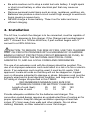
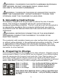
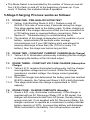
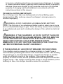
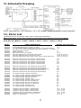
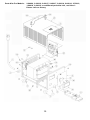
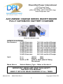
Diversified Power International 414 Century Court Piney Flats, TN 37686 (423) 538-9002 (423) 538-9202 (fax) www.DPIpower.com ACCUSENSE CHARGE SERIES ON/OFF BOARD FULLY AUTOMATIC BATTERY CHARGER *Photo for reference only* SPECIFICATIONS: Part Numbers: X-72C012xxx-xxxx X-64C014xxx-xxxx X-60C014xxx-xxxx X-48C017xxx-xxxx X-48C885xxx-xxxx X-42C017xxx-xxxx X-36C018xxx-xxxx X-24C020xxx-xxxx X-24C018xxx-xxxx Input: X = 1: X=2 120Vac, 230Vac, X=1R or 2R 120V or 230V with AC Relay Disconnect Mode Select: 72V 12A Lead-Acid Charger 64V 14A Lead-Acid Charger 60V 14A Lead-Acid Charger 48V 17A Lead-Acid Charger 48V 8.5A Lead-Acid Charger 42V 17A Lead-Acid Charger 36V 18A Lead-Acid Charger 24V 20A Lead-Acid Charger 24V 18A Lead-Acid Charger 60Hz 50Hz Selects Battery Type – Refer to Section 6. IMPORTANT: READ AND SAVE THIS SAFETY INSTRUCTION MANUAL. KEEP IT WITH OR NEAR CHARGER AT ALL TIMES Manual P/N: MNUL0018 Rev.9 Copyright © 2014 DPI 1 Table of Contents Section 1 2 3 4 5 6 Description Features Introduction User Safety Installation Grounding Preparing to Charge Pg 2 2 3 4 5 5 Section 7 8 9 10 11 12 Description 5-Stage Charge L.E.D. Display Troubleshooting Wiring Diagram Parts List Warranty Pg 7 9 10 13 13 15 Throughout the manual, look for this symbol. It means BE ALERT – YOUR SAFETY IS INVOLVED. If you do not follow these safety instructions, personal injury or property damage may occur. 1. Features Fully Automatic - starts and stops charging automatically 5 L.E.D. display to easily interpret charge and/or charge error conditions Many safety features, including Reverse Battery Protection and Wrong Battery Connections Charge algorithm controls BOTH voltage and current for precise charging Microprocessor-based control implements an intelligent charge After completion of charge, charger will maintain battery at full charge 2. Introduction The Diversified Power International (DPI) battery charger is designed to recharge deep-cycle, lead-acid batteries. It is factory preset to operate in one of 4 different charge modes; refer to Section 6 for further details. A Mode Select Jumper field, on front of charger, allows user to change Mode settings to select a different battery set. CAUTION – Incorrect Mode setting may result in permanent damage to your battery pack or property damage. Refer to Section 6 for the correct settings. Its simple method of operation and trouble-free performance makes it attractive to use. To operate, after the charger is connected to AC power, 2 simply plug in the DC cord set to activate the unit. The charger then automatically charges the battery, and also monitors the battery condition determining the proper charge profile and the correct finish phase before automatically terminating the charge when the battery is fully charged. 3. User Safety Operations Guide WARNING - RISK OF EXPLOSIVE GASES. WORKING WITH LEAD-ACID BATTERY IS DANGEROUS. EXPLOSIVE GASES DEVELOP DURING NORMAL BATTERY OPERATION. READ THIS MANUAL EACH TIME AND MAKE CERTAIN YOU FULLY UNDERSTAND IT AND FOLLOW THE SAFETY AND OPERATING INSTRUCTIONS AT ALL TIMES. To reduce risk of battery explosion, follow all safety instructions below and those published by the battery manufacturer. Review cautionary markings on vehicle or equipment containing the battery. Use of an attachment not recommended or sold by the battery charger manufacturer may result in a risk of fire, electric shock or injury to persons. Do not operate this charger if it has received a sharp blow, was dropped or otherwise damaged in any manner. Refer to a qualified service agent. Charger contains no serviceable parts. If it fails during its warranty period, contact your dealer for a warranty replacement. To reduce risk of electric shock, unplug charger from AC outlet before attempting any maintenance or cleaning. Personal Precautions While Working With Batteries Have someone within range of your voice to come to your aid if needed. Have plenty of fresh water and soap nearby in case battery acid contacts your skin, clothing or eyes. Wear eye and clothing protection and avoid touching eyes. If battery acid contacts skin or clothing, wash immediately with soap and water. If acid enters eye, immediately flush eye with running cold water for at least 10 minutes. Get medical attention immediately. NEVER smoke or allow a spark or flame in vicinity of battery. 3 Be extra cautious not to drop a metal tool onto battery. It might spark or short circuit battery or other electrical part that may cause an explosion. Remove personal metal items such as rings, necklaces, watches, etc. Batteries can produce a short-circuit current high enough to weld such items causing a severe burn. NEVER charge a frozen battery. Thaw it out for safer and more efficient charging. 4. Installation The AC line, to which the charger is to be connected, must be capable of supplying 10 amperes to this charger. If the Charger part number begins with ‘1’ connect to a 120Vac-60Hz line; if part number begins with ‘2’ connect to a 230V-50Hz line. CAUTION: TO REDUCE THE RISK OF FIRE, USE THIS CHARGER ONLY ON CIRCUITS PROVIDED WITH A MAXIMUM OF 20 AMPERE BRANCH CIRCUIT PROTECTION (CIRCUIT BREAKER OR FUSE), IN ACCORDANCE WITH THE NATIONAL ELECTRICAL CODE, ANSI/NFPA 70, AND ALL LOCAL CODES AND ORDINANCES. The use of an extension cord with the charger should be avoided. The use of an improper extension cord could result in a risk of a fire or electric shock. If an extension cord must be used, it must be UL and/or CSA approved. Locate all cords so that they will not be stepped on, tripped over or otherwise subjected to damage or stress. Extension cord must be properly wired and in good electrical condition, and large enough for the AC rating of charger as specified in this TABLE: RECOMMENDED MINIMUM AWG SIZE FOR EXTENSION CORDS FOR BATTERY CHARGERS Length of cord (feet): 25 50 100 150 AWG size of cord: 12 12 10 8 Provide adequate ventilation for the batteries and charger. The convection-cooled design requires an unobstructed flow of cooling air for proper operation. Keep all charger ventilation openings at least two inches (2") (5cm) away from walls and other objects. Do not allow clothing, blankets, or other material to cover the charger. 4 WARNING: CHARGERS CAN IGNITE FLAMMABLE MATERIALS AND VAPORS. DO NOT USE NEAR FUELS, GRAIN DUST, SOLVENTS, OR OTHER FLAMMABLES. WARNING: TO REDUCE THE RISK OF AN ELECTRIC SHOCK, KEEP THE CHARGER DRY. DO NOT EXPOSE IT TO RAIN. FOR STORAGE, KEEP THE CHARGER IN A BUILDING. 5. Grounding Instructions This battery charger must be grounded to reduce the risk of electric shock. This charger is equipped with an AC cord set having an equipment-grounding conductor. This AC cord set must be connected to an appropriate receptacle that is properly installed and grounded in accordance with the National Electrical Code and all local codes and ordinances. WARNING: IMPROPER CONNECTION OF THE EQUIPMENTGROUNDING CONDUCTOR CAN RESULT IN A RISK OF AN ELECTRIC SHOCK. The conductor with insulation having an outer surface that is green, with or without yellow stripe(s), is the equipment-grounding conductor. If repair or replacement of the charger’s AC cord set is necessary, refer to a qualified service agent, and do not connect the equipment-grounding connector to a live terminal. 6. Preparing to Charge The instructions printed on the charger are for daily reference. Chargers may be factory preset to Mode-2, but the MODE can be changed to suit different battery types by rearranging the Jumpers found under the Cover Plate located on the front of the charger, per the diagram found on the inside of the Mode Select Cover Plate, accessible by removing its 2 screws. Also, this diagram is reprinted below. Each Mode (‘color key’) is set to charge a particular Battery Type: Mode ‘1’ or Black: Mode ‘2’ or Brown: Mode ‘3’ or Red: Mode ‘4’ or Orange: Use for Flooded US Battery batteries Use for Flooded Trojan batteries Use for Flooded Exide Batteries Use for Crown / AGM Batteries Note: Most other batteries share a charge algorithm that is similar to one of the above – call your battery supplier for help. 5 Upon connection to Battery Pack, ALL FIVE L.E.D.s flash on, then off, up to 4 times. The charger is communicating the Mode Setting to you. Simply count the number of times you see ALL FIVE L.E.D.s turn on, and off. Batteries are a ‘designed component’ and the materials used in their construction determines its charge characteristic and also its suitability to your application. NEVER assume differing battery types are equal in performance or charge requirements. WARNING: ENSURE THE CHARGER AND ITS MODE SETTING IS CORRECTLY MATCHED TO THE BATTERY PACK TYPE. DAMAGE TO THE CHARGER AND BATTERIES, AND/OR PERSONAL OR PROPERTY DAMAGE MAY RESULT IF THE CHARGER OR THE MODE SETTING IS APPLIED TO THE WRONG BATTERY PACK TYPE! 6.1 Be sure area around battery is well ventilated while battery is being charged. Gas can be forcefully blown away using a non-metallic material like cardboard. 6.2 WARNING: TO REDUCE THE RISK OF AN ELECTRIC SHOCK, CONNECT ONLY TO A PROPERLY GROUNDED, SINGLE-PHASE (3WIRE) OUTLET. ALSO, REFER TO GROUNDING INSTRUCTIONS. DANGER: RISK OF ELECTRIC SHOCK! DO NOT TOUCH ANY UNINSULATED PARTS OF THE CHARGER OUTPUT CONNECTOR, BATTERY CONNECTOR, OR BATTERY TERMINALS. DANGER: VISUALLY AND MANUALLY INSPECT TO VERIFY THAT THE DC OUTPUT CORD SET, PLUG AND BATTERY CHARGING RECEPTACLE ARE IN GOOD WORKING CONDITION BEFORE EACH AND EVERY USE AND DO NOT USE THE CHARGER IF: The DC charging receptacle does not grip the DC cord set plug tightly, is loose or does not make a good electrical connection. The DC cord set plug or charging receptacle feel hotter than normal. The DC cord set plug blades or charging receptacle contacts are bent, corroded or are dark or bluish in appearance. The DC cord set plug, cords, receptacle or equipment charging wiring are cut, worn, broken or have any exposed conductors. The DC cord set plug, cords, charger or receptacles are damaged or distressed in any way. 6 Using the charger with any of the above symptoms could result in a fire, property damage or personal injury. Have your distributor, dealer or other qualified service agent, repair or replace worn or damaged parts immediately. Repairs should not be attempted by people who are not qualified. 6.3 Connect the DC cord set plug to the charging receptacle by grasping the plug body or handle and pushing the plug straight into the receptacle. Then connect charger’s AC cord set to AC power. The charger will start automatically in approximately three (3) seconds. 6.4 Ensure that the Charger Mode is appropriate for your battery voltage. For example, do not use a 48V rated charger to charge a 42v rated battery pack. WARNING: DO NOT DISCONNECT THE DC CORD SET PLUG FROM THE CHARGING RECEPTACLE WHEN THE CHARGER IS ON. THE RESULTING ARCING AND BURNING OF THE PLUG AND RECEPTACLE COULD CAUSE THE BATTERIES TO EXPLODE. IF THE CHARGER MUST BE STOPPED, FIRST DISCONNECT THE AC POWER SUPPLY CORD FROM ITS AC OUTLET, AND THEN DISCONNECT THE CHARGER DC CORD SET PLUG FROM THE CHARGING RECEPTACLE. WARNING: WHENEVER REMOVING AC OR DC CORD SET PLUGS FROM RECEPTACLES, PULL FROM THE PLUGS’ BODY AND NOT FROM THEIR RESPECTIVE CORDS. 7. 5-STAGE CHARGE 3seconds after connection to A.C. Power, (and assuming the use of the 120Vac 60Hz model part number 1-48C017xxx-xxxx, set to MODE2, all 5 charger L.E.D.s will flash on and off, twice, and then the Power L.E.D. and Detection L.E.D. will illuminate. The Detection L.E.D. will turn off when the charger’s output DC Cable connects to a battery pack (means that the charger has detected the battery pack). 7 The Mode Select is annunciated by the number of times you see all five L.E.D.s flash on and off, at the beginning of power-up. If you count ‘4’ flashes, this indicates Mode-4 operation. 5-Stage Charging Process works as follows: 7.1. STAGE ONE - PRE-QUALIFICATION TEST 7.1.1. Yellow, Light Emitting Diode (L.E.D.), flashes on and off SLOWLY at a rate of once every 2 seconds during this stage. This stage applies tests to the battery pack. Further charging is prohibited if the charger discovers a fault such as connection to a 72V battery pack or reversed battery connections. Refer to Section 9 - ‘Troubleshooting’ for understanding faults. 7.1.2. The duration of this stage is dependent on the condition of your battery - approximately 45 seconds under average circumstances, but if your 48V battery pack was allowed to severely discharge to less than 42v (10.5v for every 12v battery), then this stage can last as long as 5hrs. 7.2. STAGE TWO - CONSTANT CURRENT CHARGE (Bulk Charge) 7.2.1. Yellow L.E.D. illuminates continuously indicating that the charger is charging the battery at the full rated output. 7.3. STAGE THREE - CONSTANT VOLTAGE CHARGE (Absorption Charge) 7.3.1. Yellow L.E.D. remains illuminated continuously, but the charger now regulates voltage and not current. While the charger maintains a constant voltage, the charge current gradually decreases. 7.3.2. When the charger has determined the battery pack has reached 80-90% capacity, the Yellow and Green L.E.D.s both illuminate. 7.3.3. This stage ends when the charge is replenished to 100% capacity. 7.4. STAGE FOUR - CHARGE COMPLETE (Standby) 7.4.1. Green L.E.D. only, illuminates continuously. If the charger is supplied with an AC Disconnect Relay (1R or 2R series), the charger will disconnects itself from AC power, thereby saving energy and cost. If not supplied with AC Disconnect Relay, the charger continues to operate as a maintainer to safely maintain battery capacity at 100%, by preventing battery self-discharge. While connected to the battery, the microprocessor remains 8 active to monitor battery voltage keeps a record of elapsed time. The charger’s DC cord set can now be disconnected from the charging receptacle by grasping the plug body or handle and pulling the plug straight out of the receptacle. 7.5. RECYCLE CHARGE STAGE FIVE 7.5.1. Only after the completion of Stage 4, and after 28 days of time has elapsed, the charger will reset itself; thereby automatically initiating a new charge cycle routine and restoring battery to full capacity. If the charger is left connected to AC Power, and then the DC cord set plug is re-connected to another battery pack, the charger will restart a new charge cycle from the beginning (Stage 1). If, while charging, the charger finds an abnormal charge condition, it will attempt to shut down and indicate the ‘Condition’ by flashing one or all of its RED L.E.D.s. Refer to the ‘Troubleshooting’ section for a description of the Charge Error Condition, if you encounter a flashing RED L.E.D. 8. L.E.D. DISPLAY Under normal charge circumstances, the L.E.D.s operate as follows: Power On (Red) Illuminates continuously when AC power power is present. Refer to the section ‘TROUBLESHOOTING’ if Flashing. Abnormal Shutdown (Red) Normally not illuminated. Refer to ‘TROUBLESHOOTING’ if Flashing. Detection Error (Red) If connected to A.C. Power, but not connected to a battery pack, or battery pack is discharged to near 0V, L.E.D. will illuminate to indicate the charger cannot ‘see’ a battery connected. Refer to ‘TROUBLESHOOTING’ if Flashing. Charging (Yellow) Charge Status Indicator – it flashes or illuminates during the 5-Stage Charge Process. Refer to Section 7. Charged (Green) Illuminates continuously during the 4th Stage of the Charge Process. Refer to Section 7. 9 CAUTION: TO AVOID DAMAGE TO THE CHARGER CORDS, PLUGS, AND CHARGING RECEPTACLE, DO NOT PULL ON ANY OF THE CHARGER’S CORDS. DO NOT TWIST, ROCK, OR PULL THE PLUGS FROM THEIR MATING RECEPTACLES SIDEWAYS. 9. TROUBLESHOOTING GUIDE To be able to troubleshoot safely and effectively, it is important to read this guide completely before beginning any tests. WARNING: DO NOT DISASSEMBLE THE CHARGER. TAKE IT TO A QUALIFIED SERVICE AGENT WHEN SERVICE OR REPAIR IS REQUIRED. INCORRECT REASSEMBLY MAY RESULT IN A RISK OF ELECTRIC SHOCK OR FIRE. THE FOLLOWING PROCEDURES ARE INTENDED ONLY TO DETERMINE IF A MALFUNCTION MAY EXIST IN THE CHARGER. DANGER: TO REDUCE THE RISK OF ELECTRIC SHOCK, ALWAYS DISCONNECT THE CHARGER’S AC CORD SET FROM AC POWER AND ITS DC CORD SET PLUG FROM BATTERIES BEFORE ATTEMPTING ANY MAINTENANCE OR CLEANING WARNING: DO NOT OPERATE THE CHARGER IF IT IS MALFUNCTIONING. PERSONAL INJURY OR PROPERTY DAMAGE COULD RESULT. If any of the three red L.E.D.s flash, the charge cycle has terminated prematurely. An abnormal charging condition was detected and charging stopped due to a Charge Error Condition. Refer to the following Charge Error Table for a description of the possible failure or condition. CHARGE ERROR TABLE Flashing L.E.D.s Condition Power Abnormal Detection Battery Voltage High Off Off Flash Battery Polarity Reversed Off Flash Off Output Overload Off Flash Flash Charge Level Unbalanced Flash Off Off Excessive Charging Time Flash Off Flash Excessive Overload Flash Flash Off Excessive Discharged Flash Flash Flash 10 Battery Voltage High. Charger’s DC cord set possibly connected to a battery pack with voltage higher than the output rating of the charger. Battery Polarity Reversed. Check output connector and ensure proper polarity. Remake connections. Output Overload. While charging, and, for example, under severe motor loading, charger may shut down. This error is not very likely to occur. Charge Level Unbalanced. Caused by unbalanced battery condition. Example: some batteries are at a much higher state of charge than others. This may require replacement of the batteries. Refer to the Equipment’s Operators manual for instructions on servicing the battery pack. Excessive Charging Time. Occurs when charging took too long. Possible causes include: use of a battery load that is draining energy from the battery while the charger is trying to charge that same battery, aged or unbalanced battery conditions, etc. Excessive Overload. In the unlikely event that a heavy load is placed across the battery pack while the charger is trying to charge the battery and the charger cannot keep up with supplying energy to both the battery and the load, then, the battery voltage will decrease. Further charging is terminated. Excessive Discharged. This error is only generated by a condition found during the Pre-Qualification Test Stage. If a severely discharged battery pack did not charge up to 42v within 5 hrs, this error occurs. WARNING: ENSURE THAT EACH INDIVIDUAL BATTERY, IN THE BATTERY PACK, IS AT THE SAME STATE OF CHARGE AS ALL OTHER INDIVIDUAL BATTERIES AND THAT ALL BATTERIES ARE: equal condition, same size, and same rating. Use a voltmeter to check the voltage across each battery and confirm that no battery is higher or lower in voltage than other batteries by more than +/-0.2Vdc. DO NOT MIX DIFFERING SIZES OR TYPES or Manufacturers or mix Old with New in the same pack. Doing so may cause the battery pack 11 to become unbalanced and may cause permanent damage to charger or cause excessive battery gassing and/or personal bodily or property damage. Never use charger for any purpose contrary to its intended purpose of charging lead acid batteries in accordance with ALL instructions printed in this manual. TECHNICAL NOTES (IMPORTANT) Do not charge more than one battery pack at a time. Battery pack characteristics differ and may cause the charger’s microprocessor to function improperly. WARNING: AVOID CHARGING AN UNBALANCED BATTERY PACK! The first sign of an unbalanced battery pack is when one or more (but not all) batteries begin to gas. There are many causes that contribute to an unbalanced pack and including the design of the vehicle’s electrical system. WARNING: IF THE CHARGER’S AC OR DC OUTPUT PLUGS OR THEIR MATING RECEPTACLES ARE BROKEN, TWISTED, BENT OR LOOSE AND DOES NOT MAKE GOOD ELECTRICAL CONTACT, HAVE IT REPLACED BY A QUALIFIED SERVICE AGENT IMMEDIATELY. DO NOT USE THIS CHARGER IN THIS CONDITION AS FIRE OR PERSONAL INJURY CAN RESULT. IF THE BUILDING AC LINE CIRCUIT BREAKER OR FUSE OPENS This condition can be caused by a charger problem, a “weak” fuse or circuit breaker protecting the circuit or an overloaded circuit. If the building AC power fuse or circuit breaker blows, connect the charger to another outlet (on different circuits) in the building. If the charger operates properly on other circuits, have a qualified electrician inspect and test the original circuit. If the charger causes other fuses or circuit breakers (in the building) to blow, the charger should be tested for a problem. 12 10. Schematic Drawing NOTE: Relay optional - only installed in ‘1R’ or ‘2R’ models. Lockout circuits are model dependent 11. Parts List If replacement items are needed, order by their corresponding Kit Number. NOTE: Some parts, shown, may not apply to your model, search by Series Title as listed below: Parts Kits For Models: 1-24020, 1-36018, 1-42017, 1-48017, 1-64014, 1-72012 KIT No. PARTS DESCRIPTION Explode View Item No(s) KITS0002 KITS0001 KITS0119 KITS0107 KITS0113 KITS0055 KITS0109 KITS0115 KITS0120 Strain Relief Bushing for A.C. And D.C. Cord Set A.C. Input Cord for models equipped with Input A.C. Relay (1R/2R models) A.C. Input Cord for models not equipped with Input A.C. Relay (1- / 2- models) Bumper Feet, Set of 4 pieces Meter – 20A Scale Mode Select Cover and 2 Jumpers Enclosure without Meter Hole, Handle, Screws, Label Enclosure with Meter Hole, Handle, Screws, Label Enclosure without Meter Hole, Handle, Screws, Label (1-48015 Series only) 2, 8 1, 2 1, 2 3 13 17, 18 16, 22, 23, 24, 25, 6 16, 22, 23, 24, 25, 6 16, 22, 23, 24, 25, 6 KITS0129 KITS0106 KITS0125 KITS0156 KITS0157 Electronic Control Card for 72V Charger (1-72C012 Series) Electronic Control Card for 48V Charger (1-48C017 Series) Electronic Control Card for 42V Charger (1-42C017 Series) Electronic Control Card for 36V Charger (1-36C018 Series) Electronic Control Card for 24V Charger (1-24C020 Series) 20, 7 20, 7 20, 7 20, 7 20, 7 KITS0154 KITS0130 KITS0152 KITS0103 KITS0155 Electronic Control Card for 72V Charger (1R-72C012 Series) Electronic Control Card for 64V Charger (1R-64C014 Series) Electronic Control Card for 48V 8.5A Charger (1R-48C885 Series) Electronic Control Card for 48V Charger (1R-48C017 Series) Electronic Control Card for 36V Charger (1R-36C018 Series) 20, 7 20, 7 20, 7 20, 7 20, 7 KITS0066 KITS0067 KITS0068 KITS0069 KITS0070 KITS0027 KITS0079 KITS0080 KITS0081 KITS0126 KITS0127 D.C. Output Cord Set, Club Car Round 3-pin D.C. Output Cord Set, Club Car Crowfoot 2-pin Blade D.C. Output Cord Set, EZgo 36V D-Shape 2-Pin D.C. Output Cord Set, EZgo 48V TXT 2-Pin D.C. Output Cord Set, Yamaha, 2-Pin D.C. Output Cord Set, Yamaha, 3-Pin Powerdrive D.C. Output Cord Set, Star-Car 3-Pin Black Tip D.C. Output Cord Set, Star-Car 3-Pin Yellow Tip D.C. Output Cord Set, Star-Car 3-Pin Green Tip D.C. Output Cord Set, Red SB-50 2-Pin D.C. Output Cord Set, Gray SB-50 2-Pin 8,9 8,9 8,9 8,9 8,9 8,9 8,9 8,9 8,9 8,9 8,9 KITS0121 KITS0122 KITS0123 KITS0124 KITS0128 KITS0008 Transformer Kit, 24V Charger 1-24C020 Series Transformer Kit, 36V Charger 1-36C018 Series Transformer Kit, 48V Charger 1-48C017 Series Transformer Kit, 48V Power Supply 1-48015 Series Transformer Kit, 72V Charger (1-72C012 Series) Relay – A.C. Disconnect 10, 11, 12, 26 10, 11, 12, 26 10, 11, 12, 26 10, 11, 12, 26 10, 11, 12, 26 14, 15, 27 13 Parts Kits For Models: 2-24020, 2-36018, 2-42017, 2-48017, 2-60014, 2-64014, 2-72012, 1-24018, 2-24018, or additional parts kits info, not listed… Please call our factory 14 12. LIMITED WARRANTY Diversified Power International LLC (DPI) warrants exclusively to the original purchaser that this product will be replaced or repaired, at DPI’s option, if it fails during the first 3 years after date of purchase due to a defect in material or workmanship. In order for a claim to be processed the product must be returned to DPI (i) with all transportation charges prepaid, (ii) accompanied by a acceptable proof of purchase, and with a Return Material Authorization (RMA) number, previously obtained from DPI, printed and clearly visible on the outside of the shipping container. This warranty does not apply if the product has been modified, abused, or damaged or improperly or negligently used, connected, maintained, or operated in any manner contrary to the instructions stated in this manual or affixed to the product’s enclosure. Repair or replacement as provided under this warranty is the exclusive remedy of the purchaser, and the purchaser shall have no claim against DPI except for the breach of an express warranty stated herein. DPI shall not be liable for any incidental, consequential, or special damages for breach of any expressed or implied warranty. Except to the extent required by applicable law any implied warranty of merchantability or fitness for a particular purpose is limited in duration to the first three (3) years after the date of purchase (and lifetime Transformer warranty for original purchaser, only). Some states do not allow the exclusion or limitation of incidental or consequential damages or allow limitations on how long an implied warranty lasts, so the above limitations or exclusion may not apply to you. This limited warranty gives you specific legal rights, and you may also have other rights which vary from state to state. APART FROM THE WARRANTIES SET FORTH ABOVE, DPI MAKES NO OTHER WARRANTY, EXPRESS OR IMPLIED, WITH RESPECT TO THE SUITABILITY OR MERCHANTABILITY OF THIS PRODUCT, THE FITNESS OR THIS PRODUCT FOR ANY SPECIFIC USE OR PURPOSE, OR ANY OTHER MATTER PERTAINING TO THIS PRODUCT. Return information: DIVERSIFIED POWER INTERNATIONAL LLC 414 CENTURY COURT PINEY FLATS, TN 37686, U.S.A. 423 538-9002 RMA # ________________ For further information, product updates, technical information, or general inquiries, please visit our web site at: www.DPIpower.com 15