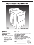
1
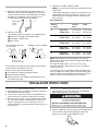
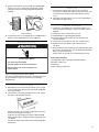
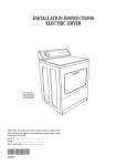
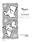
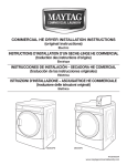
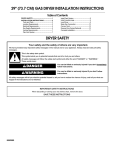
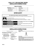
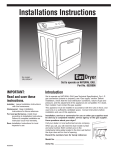
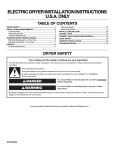
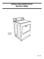
INSTALLATION INSTRUCTIONS
ELECTRIC DRYER
for models:
3RLEC8600
3RLEQ8033
W10131579A
Table of Contents
DRYER SAFETY............................................................................ 2
INSTALLATION REQUIREMENTS .............................................. 2
Tools and Parts .......................................................................... 2
Location Requirements.............................................................. 3
Electrical Requirements ............................................................ 4
Venting Requirements .............................................................. 5
Plan Vent System ...................................................................... 5
INSTALLATION INSTRUCTIONS ............................................ 6
Install Vent System .................................................................... 6
Install Leveling Legs .................................................................. 6
Electrical Connection ................................................................ 7
Level the Dryer .......................................................................... 7
Connect Vent ............................................................................ 7
Complete Installation ................................................................ 7
DRYER SAFETY
Your safety and the safety of others are very important.
We have provided many important safety messages in this manual and on your appliance. Always read and obey all safety
messages.
This is the safety alert symbol.
This symbol alerts you to potential hazards that can kill or hurt you and others.
All safety messages will follow the safety alert symbol and either the word “DANGER” or “WARNING.”
These words mean:
You can be killed or seriously injured if you don't immediately
follow instructions.
DANGER
You can be killed or seriously injured if you don't follow
instructions.
WARNING
All safety messages will tell you what the potential hazard is, tell you how to reduce the chance of injury, and tell you what can
happen if the instructions are not followed.
IMPORTANT SAFETY INSTRUCTIONS
When discarding or storing your old clothes dryer, remove the door.
SAVE THESE INSTRUCTIONS
INSTALLATION REQUIREMENTS
Tools and Parts
Gather the required tools and parts before starting installation.
Read and follow the instructions provided with any tools
listed here.
Tools needed
■
■
2
level
20 to 30 cm (8" or l0") adjustable wrench that opens
to 2,5 cm (1")
■
■
■
■
■
■
■
flat-blade screwdriver
nut driver or socket wrench — 0,62 cm (1/4")
caulking gun and compound
knife
duct tape
hex-head socket wrench — 2,5 cm (1")
tin snips
Parts supplied
Remove parts bag from dryer drum. Check that all parts were
included.
NOTE: No other fuel-burning appliance can be installed in the
same closet as a dryer.
Installation Clearances
The location must be large enough to allow the dryer door to
open fully.
4 leveling legs
Recessed Area and Closet Installation Instructions
Parts needed
Check local codes, and read electrical and venting requirements
before purchasing parts.
Location Requirements
This dryer may be installed in a recessed area or closet. For
recessed area and closet installations, minimum clearances can
be found on the serial tag on the dryer.
The installation spacing is in centimeters (inches) and is the
minimum allowable. Additional spacing should be considered for
ease of installation, servicing, and compliance with local codes
and ordinances.
If closet door is installed, the minimum unobstructed air opening
in the top and bottom is required. Louvered doors with equivalent
air openings are acceptable.
This dryer must not be installed behind a lockable door, a sliding
door or a door with a hinge on the opposite side to that of the
dryer.
The dryer must be exhausted outdoors.
No other fuel-burning appliance may be installed in the same
closet as the dryer.
Minimum Installation Clearances
Observe all governing codes and ordinances.
You will need
■ A location that allows for proper exhaust installation. The
dryer must be exhausted to the outdoors. See “Venting
Requirements.”
■ A sturdy floor to support the dryer and a total weight (dryer
and load) of 79,4 kg (175 lb). The combined weight of a
companion appliance should also be considered.
■ A level floor with a maximum slope of 2,5 cm (1") under entire
dryer. If slope is greater than 2,5 cm (1"), install Extended
Dryer Feet Kit, Part No. 279810. Clothes may not tumble
properly and models with automatic sensor cycles may not
operate correctly if dryer is not level.
■ It is important to make sure the room has an adequate air
supply for drying operation. The operation of this appliance
may affect the operation of other appliances which take their
air supply for safe combustion from the same room.
■ Adequate ventilation must be provided to avoid a backflow of
gases into the room from appliances burning other fuels,
including open fires. If in doubt consult the appliance
manufacturers.
Do not operate your dryer at temperatures below 7ºC (45ºF). At
lower temperatures, the dryer might not shut off at the end of an
automatic cycle.
The dryer must not be installed or stored in an area where it will
be exposed to water and/or weather.
Check code requirements. Some codes limit, or do not permit,
installation of the dryer in garages, closets, mobile homes, or
sleeping quarters. Contact your local building inspector.
35,6 cm
(14") max.
45,7 cm
(18")
Closet
door
10 cm
(4")
2,5 cm (1")
2,5 cm (1")
68,6 cm
(27")
2,5 cm (1")
Closet side view
Recessed front view
Additional clearances for wall, door and floor moldings may be required or if external
exhaust elbow is used.
7,6 cm (3")
310 cm2*
(48"2)
Front
View
closet
door
155 cm2*
(24"2)
7,6 cm (3")
*Opening is the minimum for a closet door.
Louvered doors with equivalent air openings are acceptable.
3
Electrical Requirements
Product Dimensions
Dimensions shown with feet extended 2,5 cm (1") from bottom of dryer.
terminal block cover
27,9 cm
(11")
power supply
cord/cable
strain relief
35,6 cm
(14")
The dryer door
extends
35,6 cm (14")
from the front
of the dryer
when fully
opened.
109,5 cm
(43 ¹⁄₈")
97,2 cm
(38 ¹⁄₄")
This dryer is supplied without an electric cord and plug. It must
be connected by a competent electrician to a single-phase
electricity supply at the voltage shown on the dataplate, using a
suitable fixed wiring installation in accordance with local and
national wiring regulations.
■ A 3-wire circular cord of minimum conductor size 2.5 mm2
cross-section area should be used.
■ A 30A supply fuse should be used, and a switch with a
minimum contact separation of 3 mm in both poles must be
incorporated into the fixed wiring for dryer disconnection. The
dryer should be positioned so that the disconnection switch is
easily accessible to the user.
■ A cord clamp bush is provided on the dryer, and should be
tightened on completion of wiring. The electrical mains
terminals are located behind the small rear access panel
(terminal block cover), and connections should be made in
accordance with the terminal markings. Remember to replace
the terminal access panel (terminal block cover).
NOTE: In accordance with the European EMC Directive
(89/336/EEC) the maximum electricity supply system impedance
to which the electric dryer should be connected is declared to be
0.302 Ohm + j0.189 Ohm.
74,3 cm
(29 ¹⁄₄")
68,6 cm (27")
WARNING
Side swing door clearances
57,8 cm (22 ³⁄₄")
9,8 cm (3 ⁷⁄₈")
48,9 cm
(19 ¹⁄₈")
Electric Shock Hazard
Electric earthing is required on this dryer.
57,8 cm (22 ³⁄₄")
Do not earth to a gas pipe.
Do not have a fuse in the neutral or earthing circuit
Location must be large enough to fully open dryer door.
Check with a qualified electrician to be sure the dryer is
properly earthed.
Exhaust dimensions
Failure to follow these instructions could result in
death, fire, or serious injury.
10 cm
(4")
35,9 cm
(14¹⁄₈")
back exhaust
4
10,8 cm
(4¹⁄₄")
26 cm
(10 ¹⁄₄")
left or right
side exhaust
If codes permit and an additional earth bond wire is used, it is
recommended that a competent electrician determine that the
earth bond path is adequate.
Recommended Earthing Method
■ It is your responsibility to contact a qualified electrical installer
to ensure that the electrical installation is adequate and in
conformance with all local codes and ordinances.
Improper venting can cause moisture and lint to collect
indoors, which may result in:
■ Moisture damage to woodwork, furniture, paint,
wallpaper, carpets, etc.
■ Housecleaning problems and health problems.
EARTHING INSTRUCTIONS
SAVE THESE INSTRUCTIONS
IMPORTANT: Observe all governing codes and ordinances.
Use a heavy metal vent. Do not use plastic or metal foil vent.
Rigid metal vent is recommended to prevent crushing and
kinking.
Flexible metal vent must be fully extended and supported when
the dryer is in its final position. Remove excess flexible metal vent
to avoid sagging and kinking that may result in reduced airflow
and poor performance.
An exhaust hood should cap the vent to prevent rodents and
insects from entering the home.
Exhaust hood must be at least 30,5 cm (12") from the ground or
any object that may be in the path of the exhaust (such as
flowers, rocks or bushes, etc.).
If using an existing vent system, clean lint from the entire length
of the system and make sure exhaust hood is not plugged with
lint. Replace any plastic or metal foil vent with rigid metal or
flexible metal vent.
Venting Requirements
Plan Vent System
Route the Vent
The exhaust outlet is located at the center of the rear of the dryer.
The exhaust vent can be routed up, down, left, right or straight
out the back of the dryer.
A
WARNING: To reduce the risk of fire, this dryer MUST BE
EXHAUSTED OUTDOORS.
■ The dryer exhaust must not be connected into any gas vent,
chimney, wall, ceiling, or concealed space of a building.
■ Do not use an exhaust hood with a magnetic latch.
■ Do not install flexible non-metal vent.
■ Do not install metal vent that is smaller than 10 cm (4") in
diameter.
■ Do not install flexible vent in enclosed walls, ceilings or floors.
■ 10 cm (4") heavy metal vent and clamps must be used.
■ Use 10 cm (4") clamps to seal all joints. Vent must not be
connected or secured with screws or other fastening devices
which extend into the interior of the vent. Do not use duct
tape.
B
C
A. Standard rear offset exhaust installation
B. Left or right side exhaust installation
C. Bottom exhaust installation
The design of the flue system should ensure that any condensate
formed when operating the appliance from cold, is either retained
and subsequently evaporated or discharged. Following these
installation instructions should adequately meet this requirement.
5
Vent System Length
1. Select the route that will provide the straightest and most
direct path outdoors. Plan the installation to use the fewest
number of elbows and turns. Avoid making 90° turns. When
using elbows or making turns, allow as much room as
possible. Bend vent gradually to avoid kinking.
A
Exhaust Air Flow
A. Better
B. Good
B
2. Determine vent length.
The maximum length of the exhaust system depends upon:
■ The type of vent (rigid metal or flexible metal).
■ The number of elbows used.
■ Type of hood.
Recommended hood styles
are shown here.
10 cm (4")
Number of Type of vent
90º turns
or elbows
Box or
louvered
hoods
Angled
hoods
0
Rigid metal
Flexible metal
15,8 m (52 ft.)
9,4 m (31 ft.)
13,4 m (44 ft.)
7,0 m (23 ft.)
1
Rigid metal
Flexible metal
13,4 m (44 ft.)
7,9 m (26 ft.)
11,0 m (36 ft.)
5,5 m (18 ft.)
2
Rigid metal
Flexible metal
11,0 m (36 ft.)
6,7 m (22 ft.)
18,5 m (28 ft.)
4,3 m (14 ft.)
3
Rigid metal
Flexible metal
8,2 m (27 ft.)
6,1 m (20 ft.)
6,4 m (21 ft.)
3,7 m (12 ft.)
4
Rigid metal
Flexible metal
6,1 m (20 ft.)
5,5 m (18 ft.)
4,3 m (14 ft.)
3,0 m (10 ft.)
Angled hood style acceptable.
B
A
3. Determine the number of elbows needed.
NOTE: Do not use vent runs longer than specified in the Vent
Length Chart.
The following chart helps you determine your maximum vent
length based on the number of 90° turns or elbows you will
need and the type of vent (rigid or flexible metal) and hood
that you will use.
Vent Length Chart
10 cm
(4")
6,4 cm
(2¹₂")
10 cm (4")
A. Box hood style
B. Louvered hood style
See the exhaust vent length chart that matches your hood type
for the maximum vent lengths you can use.
Exhaust systems longer than specified will:
■ Accumulate lint, creating a potential fire hazard.
■ Shorten the life of the dryer.
■ Reduce performance, resulting in longer drying times and
increased energy usage.
NOTE: Side and bottom exhaust installations have a 90º turn
inside the dryer. To determine maximum exhaust length, add one
90º turn to the chart.
The maximum length using a 5,1 cm x 15,2 cm (2" x 6")
rectangular vent with 2 elbows and a 6,4 cm (2-1/2") exhaust
hood is 2,4 m (8 ft.).
For exhaust systems not covered by exhaust vent length charts
(such as multiple unit hookups, plenums, and power-assist fans),
see Service Manual, Part No. 603197. (To purchase the Service
Manual, contact your local authorised service company).
INSTALLATION INSTRUCTIONS
Install Vent System
1. Install exhaust hood. Use caulking compound to seal exterior
wall opening around exhaust hood.
2. Connect vent to exhaust hood. Vent must fit inside exhaust
hood. Secure vent to exhaust hood with 10 cm (4") clamp.
3. Run vent to dryer location. Use the straightest path possible.
See “Vent System Length.” Avoid 90º turns. Use 10 cm (4")
clamps to seal all joints. Do not use duct tape, screws or
other fastening devices that extend into the interior of the vent
to secure vent.
Install Leveling Legs
1. Open dryer door and remove drying rack, if included. Wipe
drum with damp cloth to remove any dust.
2. Take two cardboard corners from dryer carton and place them
on floor in back of dryer. Firmly grasp body of dryer and
gently lay it on its back on the cardboard corners.
6
3. Start to screw legs into holes by hand. Use an adjustable
wrench or 2,5 cm (1") hex-head socket wrench to finish
turning legs until you reach the ridge with the diamond
marking.
Connect Vent
1. Connect vent to dryer outlet using 10 cm (4") clamp. If
connecting to existing vent, make sure the vent is clean. The
vent must fit over the dryer outlet and inside the exhaust
hood.
2. Move dryer into final position. Do not crush or kink exhaust
vent. Make sure dryer is level.
A
Complete Installation
A. diamond marking
4. To protect the floor, use a large flat piece of cardboard from
the dryer carton. Stand dryer up on the cardboard.
Electrical Connection
WARNING
Electric Shock Hazard
This dryer must be earthed.
Securely tighten all electrical connections.
Failure to do so can result in death, fire, or
electric shock.
1. Check to be sure all parts are now installed. If there is an
extra part, go back through the steps to see which step was
skipped.
2. Check to be sure you have all of your tools.
3. Properly dispose of all packaging materials.
4. Check the dryer’s final location. Be sure the vent is not
crushed or kinked.
5. Check to be sure the dryer is level. See “Level the Dryer.”
6. Read the Use & Care Guide to fully understand your
new dryer.
7. Select a full heat cycle (not the air cycle) and start dryer. After
five minutes, open dryer door. You should feel heat inside the
dryer or on the exhaust vent.
If dryer makes an unusual noise, check that dryer is level.
Technical Specifications
(see rating plate in door opening for full model details)
220-240V ~ 50 Hz, 1 ph
4575W, IPX4
Clothes capacity: 9.0 Kg max.
This is a 3-wire dryer which must be earthed.
This dryer is supplied without an electric cord and plug, it must
be connected by a competent electrician. See “Electrical
Requirements.”
Level the Dryer
1. Move dryer close to its permanent location. Leave enough
room to connect the exhaust vent. Remove the cardboard
from under the dryer.
2. Check levelness of dryer by placing a level on top of dryer,
first side to side, then front to back.
If dryer is not level, use a wrench to adjust dryer legs up or
down and check again for levelness.
If legs are not long enough to level dryer, order Extended
Dryer Feet Kit, Part No. 279810 (sold two legs per kit), from
your dealer.
The dryer must be level to reduce noise and assure proper
performance.
7
W10131579A
© 2007, Whirlpool Corporation
10/2007
Printed in U.S.A.