1
Thermo Fisher Scientific
WX Ultra Series
WX 100, WX 90, WX 80
Instruction Manual
50105750-4
October 2010
IMPORTANT!
Please reference this page for the most up-to-date information on the
following*
•
• web site addresses
• contact information
copyright and trademark information
*All subsequent pages in this manual may have incorrect web site addresses and contact information.
©2013 Thermo Fisher Scientific Inc. All rights reserved. Delrin, TEFLON, and Viton are registered
trademarks of DuPont. Noryl is a registered trademark of SABIC. POLYCLEAR is a registered
trademark of Hongye CO., Ltd. Hypaque is a registered trademark of Amersham Health As. RULON A
and Tygon are registered trademarks of Saint-Gobain Performance Plastics. Alconox is a registered
trademark of Alconox. Ficoll is a registered trademark of GE Healthcare. Haemo-Sol is a registered
trademark of Haemo-Sol. Triton X-100 is a registered trademark of Sigma-Aldrich Co. LLC. All other
trademarks are the property of Thermo Fisher Scientific Inc. and its subsidiaries.
Manufacturer
Thermo Fisher Scientific
Robert-Bosch-Straße 1
D - 63505 Langenselbold
Germany
Thermo Fisher Scientific Inc. provides this document to its customers with a product purchase to use
in the product operation. This document is copyright protected and any reproduction of the whole or
any part of this document is strictly prohibited, except with the written authorization of Thermo Fisher
Scientific Inc.
The contents of this document are subject to change without notice. All technical information in this
document is for reference purposes only. System configurations and specifications in this document
supersede all previous information received by the purchaser.
Thermo Fisher Scientific Inc. makes no representations that this document is complete,
accurate or error-free and assumes no responsibility and will not be liable for any errors,
omissions, damage or loss that might result from any use of this document, even if the
information in the document is followed properly.
This document is not part of any sales contract between Thermo Fisher Scientific Inc. and a
purchaser. This document shall in no way govern or modify any Terms and Conditions of Sale, which
Terms and Conditions of Sale shall govern all conflicting information between the two documents
C
Contents
Chapter 0
Preface - Intended use and safety definitions ............................................................................................... iii
Safety Definitions ..................................................................................................................................iii
Important safety reminder .....................................................................................................................iv
Chapter 1
Description...........................................................................................................................................................1-1
General description............................................................................................................................. 1-1
External view of ultracentrifuge ...................................................................................................... 1-2
Design ................................................................................................................................................ 1-3
Control panel ................................................................................................................................. 1-3
Rotor chamber................................................................................................................................ 1-6
Safety devices.................................................................................................................................. 1-7
Rotor adapter ................................................................................................................................. 1-8
Chapter 2
Operation ..............................................................................................................................................................2-1
Run preparation ................................................................................................................................. 2-2
Starting up the ultracentrifuge ........................................................................................................ 2-3
Preparing tubes/bottles and rotor.................................................................................................... 2-4
Basic operation ................................................................................................................................... 2-4
Setting run conditions .................................................................................................................... 2-4
Setting user ID code ....................................................................................................................... 2-9
Using Rotor Life Management ..................................................................................................... 2-10
Basic operating procedure................................................................................................................. 2-11
Normal operation ......................................................................................................................... 2-13
Zonal operation ............................................................................................................................ 2-15
Acceleration and deceleration rates ................................................................................................... 2-17
How to use the FUNCTION field ................................................................................................... 2-19
Programmed operation ................................................................................................................. 2-21
Step-mode operation .................................................................................................................... 2-32
RTC (real-time control) feature .................................................................................................... 2-40
Displaying and setting RCF.......................................................................................................... 2-48
Setting w2T.................................................................................................................................. 2-56
Defrost function ........................................................................................................................... 2-58
Setting and resetting zonal operation ............................................................................................ 2-59
Rotor management ........................................................................................................................... 2-60
Rotor life management ................................................................................................................. 2-60
Automatic rotor deration .............................................................................................................. 2-61
Automatic rotor exclusion............................................................................................................. 2-61
Registering a rotor ........................................................................................................................ 2-61
Deleting a registered rotor ............................................................................................................ 2-64
Updating the existing data for a rotor ........................................................................................... 2-65
When power failure occurs ............................................................................................................... 2-66
Features of the menu screen.............................................................................................................. 2-69
Thermo Scientific
WX Ultra Series
i
Contents
Centrifuge scheduler..................................................................................................................... 2-69
User list ........................................................................................................................................ 2-71
Alarm information........................................................................................................................ 2-76
Rotor catalog ................................................................................................................................ 2-77
User Customizations..................................................................................................................... 2-77
Print utilities (option)....................................................................................................................... 2-81
Operating procedure..................................................................................................................... 2-82
Contents of print utilities ............................................................................................................. 2-84
Automatic run result printing ....................................................................................................... 2-86
Printer fault handling ................................................................................................................... 2-87
Lockout (optional)............................................................................................................................ 2-88
Chapter 3
Maintenance........................................................................................................................................................3-1
Rotor chamber.................................................................................................................................... 3-1
Drive spindle ...................................................................................................................................... 3-2
Cabinet............................................................................................................................................... 3-2
Replacement parts .............................................................................................................................. 3-2
Service decontamination policy .......................................................................................................... 3-2
Chapter 4
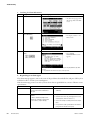
Troubleshooting ..................................................................................................................................................4-1
Alarm indicators ................................................................................................................................ 4-1
Diagnosed problems - requiring maintenance..................................................................................... 4-3
Non-diagnosed problems ................................................................................................................... 4-3
Chapter 5
Preinstallation .....................................................................................................................................................5-1
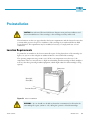
Location Requirements....................................................................................................................... 5-1
Electrical requirements ....................................................................................................................... 5-2
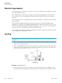
Leveling.............................................................................................................................................. 5-2
Moving the ultracentrifuge ................................................................................................................. 5-3
Chapter 6
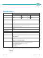
Specifications .....................................................................................................................................................6-1
Chapter 7
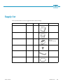
Supply list.............................................................................................................................................................7-1
Appendix A Service Decontamination Policy ....................................................................................................................A-1
Appendix B Condensed operating instructions .................................................................................................................B-1
Appendix C Chemical Compatibility Chart .........................................................................................................................C-1
Appendix D WARRANTY.........................................................................................................................................................D-1
Appendix E Contact Information ........................................................................................................................................... E-1
ii
WX Ultra Series
Thermo Scientific
P
Preface - Intended use and safety definitions
This manual is a guide to the use of the Sorvall WX Ultra series ultracentrifuge.
Information herein has been verified and is believed adequate for the intended use of the centrifuge.
Because failure to follow the recommendations set forth in this manual could produce personal injury
or property damage, always follow the recommendations set forth herein. Thermo does not guarantee
results and assumes no obligation for the performance of centrifuges or other products that are not
used in accordance with the instructions provided. This publication is not a license to operate under,
nor a recommendation to infringe upon, any process patents.
Safety Definitions
DANGER, WARNING, CAUTION, and NOTE within the text of this manual are used to
emphasize important and critical instructions.
DANGER Informs the operator of an extreme hazard or an unsafe practice that will result
in death or serious injury.
WARNING
Informs the operator of a hazard or an unsafe practice that could result in
serious injury or death, affect the operator's health, or contaminate the environment.
CAUTION Informs the operator of a hazard or an unsafe practice that could cause minor
injury, or result in damage of equipment or property.
Note Highlights essential information that is not hazard-related.
DANGER, WARNING and CAUTION information is accompanied by a hazard symbol and appears
throughout the manual, both on the Important Safety Reminder pages and near the information it
corresponds to.
Before you operate the centrifuge, we recommend that you read this instruction manual thoroughly,
particularly all DANGERS, WARNINGS and CAUTIONS.
Never operate the centrifuge without first considering all items on the Important Safety Reminder
pages, and never operate the centrifuge in any manner not described in this instruction manual.
Thermo Scientific
WX Ultra Series
iii
Preface - Intended use and safety definitions
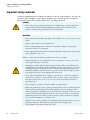
Important safety reminder
Important safety reminder
Certain potentially dangerous conditions are inherent to the use of all centrifuges. To ensure safe
operation of this centrifuge, anyone using it should be aware of all safe practices and take all
precautions described below and throughout these operating instructions.
DANGER
• Before removing any cabinet panel (such as for maintenance or repair), always turn
the main Power Switch OFF and unplug the centrifuge, then wait at least three
minutes to eliminate the potential for severe electric shock.
WARNING
• Never exceed the maximum rated speed of the installed rotor; to do so can cause rotor
failure.
• Always reduce (derate) rotor speed whenever:
1. The rotor speed/temperature combination exceeds the solubility of the gradient
material and causes it to precipitate.
2. The compartment load exceeds the maximum allowable compartment load (or design
mass) specified for your rotor.
Failure to reduce speed under these conditions can cause rotor failure.
• Always inspect the rotor as specified in your rotor manual. Do not use a rotor that
shows signs of damage or corrosion.
• Centrifuges routinely deal with high energy levels and could move suddenly in the
unlikely event of rotor failure. During centrifuge operation, never lean on or move the
centrifuge, keep the surrounding area clear of objects (including all hazardous and
flammable materials), and do not work on top of or next to the centrifuge (as a rule,
keep people and objects at least 300 mm [12 inch] away).
• Never unlock the chamber door, attempt to open the door, or otherwise attempt to
touch the rotor while it is rotating. In the event of a power outage, it can take more
than three hours for the rotor to stop - be sure to wait at least three hours before
opening the door.
• Never attempt to override or otherwise disable any safety features.
• When using radioactive, toxic, or pathogenic materials, be aware of all characteristics
of the materials and the hazards associated with them in the event leakage occurs
during centrifugation. If leakage does occur, neither the centrifuge nor the rotor can
protect you from particles dispersed in the air. To protect yourself, we recommend
additional precautions be taken to prevent exposure to these materials, for example,
use of controlled ventilation or isolation areas.
• Always be aware of the possibility of contamination when using radioactive, toxic, or
pathogenic materials. Take all necessary precautions and use appropriate
decontamination procedures if exposure occurs.
iv
WX Ultra Series
Thermo Scientific
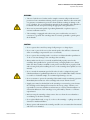
Preface - Intended use and safety definitions
Important safety reminder
WARNING
• The use of sealed rotors, buckets and/or sample containers will provide increased
protection from contamination during routine operation. However, these items will
not guarantee contamination protection from accidents resulting in damage to the
rotor or buckets. Do not run hazardous materials in the centrifuge unless placed in a
biohazard enclosure and operated using all appropriate safety precautions.
• Never use any materials capable of producing flammable or explosive vapors, or
extreme exothermic reactions.
• The centrifuge is equipped with a three-wire power cord that has one wire for
connection to ground. The centrifuge must be correctly grounded to guard against
shock hazards.
CAUTION
• Do not operate the control keys using a ball-point pen or a sharp object.
• Do not run or precool the rotor at the critical speed as this will have a detrimental
effect on centrifuge component life (see rotor manual).
• Do not operate the centrifuge with a rotor that is not balanced within specification.
To do so can cause damage to the centrifuge drive assembly.
• Always make sure the rotor is correctly assembled and properly seated on the
centrifuge drive spindle before operation. If using a swinging-bucket rotor, always
make sure that a bucket is installed at each position and that each is properly seated
and can swing freely after installing the rotor on the centrifuge drive spindle (see rotor
manual).
• Do not exceed the maximum speed of the tubes, bottles, or adapters being used.
Check manufacturer's published specifications or see Sorvall Product Guide; if unsure,
to avoid loss of valuable sample, we recommend performing a test run.
• Do not continue to operate the centrifuge if abnormal sounds occur during operation.
Immediately discontinue use of the centrifuge and contact Thermo Service.
• Supply power must be checked before the centrifuge is connected to power because
the centrifuge can be damaged if connected to the wrong voltage. Thermo is not
responsible for incorrect installation and warranty is void if an initial installation or
electrical modification of the centrifuge is not performed by Thermo or a Thermo
representative.
• Before moving the centrifuge, always remove the rotor from the rotor chamber to
avoid damage to the drive assembly.
• Do not place fluids inside, on top of, or close to the centrifuge --- spillage can result in
electrical or mechanical failure.
• Always operate and maintain the centrifuge and all rotors as instructed in this manual
and in the rotor manual(s).
Thermo Scientific
WX Ultra Series
v
Preface - Intended use and safety definitions
Important safety reminder
vi
WX Ultra Series
Thermo Scientific
1
Description
General description
The Sorvall WX Ultra series ultracentrifuges are designed and manufactured based on our long
experience in the development of centrifuges; they are easy to use and highly reliable. Features include
the following:
1. Maximum speed of 100,000 rpm (802,006 x g)
2. Control panel is simple with easy key operation and easy-to-see liquid crystal screen.
3. The displayed language can be switched over between English and Japanese.
4. The real-time control (RTC) feature enables setting a start time or a finish time, thus letting you
run your machine at a desired date and time.
5. Centrifugal force (RCFmax and RCFavg) can be displayed and set.
6. Twenty varieties of nine stepped modes can be programmed for a wide range of applications.
7. Various alarms notify users of causes and necessary actions when fault conditions are detected
allowing easier and quicker troubleshooting.
8. Space saving design. The installation area required is 0.81 m2 (90 x 90 cm) pr 9.0 ft2 (3.0 x 3.0 ft). Lower
top deck makes it easy to install and remove the rotor.
9. Low noise level makes the ultracentrifuge suitable for use in any laboratory.
10. Samples can be easily balanced visually.
11. CFC-free thermoelectric cooling system with greater cooling capacity.
Advanced features (options)
The options of the Sorvall WX Ultra series ultracentrifuges are: Compass Software, Lockout Kit, and a
Printer.
The Compass Software is a calculation/simulation system for centrifuge support that is compatible with
Windows R 2000 / XP Professional. Compass Centrifugation software helps determine appropriate run
conditions prior to starting centrifugal separation, and calculates optimum centrifuge and rotor run
conditions for materials in which proper run conditions are unknown. For more information on this
please consult the Compass Operator's Manual.
The Lockout Kit limits centrifuge access to a group of registered users (up to 40) which is controlled by
lab managers/supervisors (up to 3). For more information on this see page 2-95, Lockout.
The printer provides hard copy reports of information maintained in the centrifuge including: Set and
actual run conditions, rotor use, programmed memory contents, and others. For more information on
this see page 2 - 89, Print Utilities.
Thermo Scientific
WX Ultra Series
1-1
Description
General description
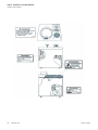
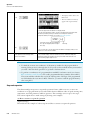
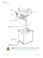
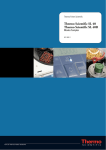
External view of ultracentrifuge
The WX Series ultracentrifuge have the same external view, except for the model name printed on front
cover. The following is the external view of the WX ultracentrifuge.
External view of ultracentrifuge
Display panel
Safety cover
690 mm (27.2 in)
790 mm (31.1in)
850 mm (33.5 in)
1000 mm (39.4 in)
Door
Top deck
Operation key
Rotor rubber mat
Power switch
Front cover
Note * This height is measured from level floor surface.
Figure 1-1 External view of the Sorvall WX Ultra series
1-2
WX Ultra Series
Thermo Scientific
Description
Design
Design
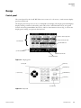
Control panel
The control panel for the Sorvall WX Ultra series consists of a color screen, a touch sensitive display
panel and a keyboard.
The display panel incorporates an easy-to-read liquid crystal display. The display panel (field display)
displays running conditions and running status (this screen is called the Run Screen), along with
features such as Programmed Run, Rotors List, and User Customization Screens. Fig. 1-2 shows the
display panel, and Fig.1-3 represents the keyboard.
(1) Field display
{
} Operation state display field
} Setting value display field
(2) FUNCTION field
(3) Message indicator
(4) RUN mode indicator
(5) Vacuum indicator
Figure 1-2 Display panel
(9) ESC key
(12) Key pad
(10) MENU key
(8) VACUUM key
(11) Cursor key
(7) STOP key
(6) START key
Figure 1-3 Keyboard
Thermo Scientific
WX Ultra Series
1-3
Description
Design
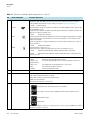
Table 1-1 [Functions of the display panel-keyed by item no. to fig. 1-2]
No.
Name and Symbol
Functions and actions
(1)
Field display
Displays various fields.
The SPEED, TIME, and TEMP fields give the current status indicator in the top row and the
setting indicator in the bottom row. (For setting, see Section “Setting run conditions”.)
SPEED
TIME
TEMP
• SPEED
(Speed indicator)
(Top row) Displays speeds in increments of 10 rpm at lower than 5,000 rpm, and in steps of 100
rpm at 5,000 rpm or more.
(Bottom row) Sets speeds from 1,000 to maximum speed in increments of 100 rpm. The lower two
digits (one, ten positions) display zeros.
• TIME
(running time indicator)
(Top row) Displays the remaining operation time or the time elapsed during operation if settings
are performed on the User Customization screen. If the running time is set to HOLD, this field
displays time elapsed.
(Bottom row) Specifies a setting in the range from 1 minute to 99 hours 59 minutes in steps of
minutes and hours.
• TEMP
(temperature indicator)
(Top row) Displays in steps of 0.1 °C.
(Bottom row) Sets a setting in the range from 0 °C to 40 °C in increments of 0.1 °C
• ACCEL
(acceleration mode indicator). Displays acceleration modes 1 through 9.
• DECEL
(deceleration mode indicator). Displays deceleration modes 1 through 9, along
with free coast (F).
(2)
Function field
• ID CODE
• RLM
• PROG • RTC
programmed run.
• RCF • ω2T
• DEF
• ZONAL
Sets an ID code.
Switches to the Rotor Management screen.
Sets, recalls programmed runs or sets the time and the end time for a
Sets and displays the centrifugal force or sets an ω2T
Sets and resets the defrost function.
Sets the zonal operation mode.
(3)
Message indicator
Displays an alarm message and various suggestions for operation.
(4)
Run mode indicator
The following terms are displayed:
STOP, ACCEL, RUN (running at the set speed)
DECEL, WAIT (waiting for vacuum during acceleration)
ZONAL (for zonal operation)
DELAY (until the start time in an RTC run)
(5)
VACUUM indicator
Displays the following four stages according to the vacuum of the rotor chamber.
(1)
Atmospheric state. The vacuum pump is not activated.
(2)
Low vacuum. The rotor waits at 4,000 rpm until the vacuum reaches an inter-
mediate level
(3)
Intermediate vacuum.
(4)
High vacuum.
Note If the sample is sensitive to a temperature rise, do not press the START key until the
chamber is at high vacuum level.
1-4
WX Ultra Series
Thermo Scientific
Description
Design
Table 1-2 [Functions of keyboard-keyed by item no. to fig. 1-3]
No.
Name and Symbol
Functions and actions
(6)
START key
Starts rotor rotation. If VACUUM is off, this key activates the vacuum pump and starts
temperature control.
(7)
STOP key
Stops rotor rotation.
(8)
VACUUM key
Starts up the vacuum pump and activates air vent (As soon as vacuum pump is on, temperature control starts.) Air vent for vacuum chamber after a run cannot be opened as
long as the rotor is spinning.
(9)
ESC key
Moves the display back to the screen at the preceding level (for example, to switch
back from the Menu Screen to the Run Screen).
(10)
MENU key
Displays the Menu Screen.
The Menu Screen offers the choice of Centrifuge Scheduler, User List, Alarm Information, Rotor Catalog, and User Customization Routines.
(11)
Cursor key
a. Displays the cursor on the Run Screen, putting the display into input wait status.
b. Move the cursor on the screen.
1. Moves the cursor up
2. Moves the cursor down
3. Moves the cursor to the right
4. Moves the cursor to the left
(12)
Numeric key
Used to type numbers for setting run conditions.
During time and temperature entry: Moves cursor from hours to minutes.
Acts as decimal point for data entry.
a. During operation time entry: sets continuous run.
b. When entering deceleration conditions: sets a free coast.
Use this when you have entered the wrong value while entering an
operating condition or entering a number or when the alarm device is
activated.
Functions of this key
a. This key clears the cursor-carrying input field and returns you to the
preinput state.
b. Use this key to clear an alarm signal. If more than one alarm signal is
on, this key will clear them one by one.
Registers the entered value.
Thermo Scientific
WX Ultra Series
1-5
Description
Design
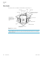
Rotor chamber
The structure of the rotor chamber (vacuum chamber) is shown in Fig. 1-4.
Drive spindle
Chamber door seal
Speed sensor
Overspeed detector
(detecting any instance
exceeding the maximum
allowable speed of the
rotor)
Handle
Chamber door
Temperature sensor (measuring
the temperature of the rotor)
Door lock system
Vacuum chamber
Guard
Bowl (Rotor Chamber)
Thermoelectric cooling element
(cooling the rotor)
Figure 1-4 Rotor chamber
Note If sample or water drops to the window of the temperature sensor, it may cause an incorrect
detection. Whenever the sensor is wet, wipe it with a clean, dry cloth. Take care not to scratch the
surface of the sensor.
1-6
WX Ultra Series
Thermo Scientific
Description
Design
Safety devices
(1) Containment
Should a rotor failure occur, the guard ring will contain the contents of the rotor inside the centrifuge
(Fig. 1-4).
(2) Imbalance detector
If during operation the vibration of the rotor becomes excessive due to serious imbalance or improper
bucket setting, the imbalance detector detects the situation and decelerates the rotor immediately.
However, the ultracentrifuge is designed to tolerate imbalance associated with visual balancing-it is
equipped with an imbalance tolerant drive. (For more information on the balancing of rotors, see
Section 2-1-2, “Preparing tubes/bottles and rotor”.)
(3) Door lock system
The chamber door automatically locks for safety while the rotor is spinning. When the power supply is
off, the door remains locked. The door can only be opened and closed when the rotor is at rest and the
rotor chamber is vented. Unless the door is closed, the rotor will not start rotating except in zonal
mode. To open the door in the event of a power failure, see Section 2-7, “When power failure occurs”.
(4) Speed sensor and overspeed detector
For protection in the event of entry errors the ultracentrifuge is provided with an automatic system to
stop the rotor when its speed exceeds the maximum allowable speed. If a speed higher than the
maximum permitted speed is set, the ultracentrifuge will detect the mistake before the speed reaches
3000 rpm, and then will display an alert message and decelerate the rotor to a stop.
Thermo Scientific
WX Ultra Series
1-7
Description
Design
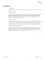
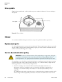
Rotor adapter
Overspeed Decal
The overspeed decal located on the rotor base has alternating black and white bands. The number of
bands corresponds to the maximum permitted speed of the rotor. (See Fig. 1-5.)
Overspeed decal
Standard rotor with
overspeed decal
Figure 1-5 Standard rotor
To protect the overspeed decal, be sure to store the rotor on the rotor stand provided. (See Fig. 1-6.)
Figure 1-6 Rotor stand
1-8
WX Ultra Series
Thermo Scientific
2
Operation
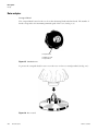
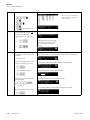
The Sorvall WX Ultra series ultracentrifuges are capable of operation in more than one mode to meet a
wide range of applications. The outline of each available mode is given below:
Outline
Reference
Section Normal operation
Speed
Normal operation
Time
Speed
Speed
Programmed operation
You can store set run conditions in memory for later use in
repeated operation.
Store
Recall
Section How to use the
FUNCTION field
Section Programmed
operation
Time
Time
More than one normal operation can be combined into a
sequence of operations or step for successive centrifugation.
Section Step-mode
operation
Speed
Step-mode operation
Time
Run starts or completes at a required date and time.
A finish date
and time required
Speed
RTC (real-time control) operation
START
key ON
Section RTC (real-time
control) feature
Time
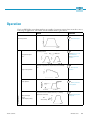
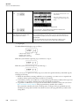
Thermo Scientific
RCF (centrifugal
force)
value display setting
RCF
value setting
Section Displaying and
setting RCF
Speed
Optional features
This feature calculates centrifugal force (RCF) values from
set speed. It can also calculate reversely, i.e., finding
speed from such values.
Time
WX Ultra Series
2-1
Operation
Run preparation
ω2T setting
Section Setting w2T.
Speed
Calculates and displays the running time from the set values of speed and ω2T.
Time
Zonal operation is a mode of operation using a zonal
rotor.
Section Zonal operation.
Optional features
Speed
Zonal operation
Zonal speed
Time
Run preparation
WARNING
1. Never use any materials capable of producing flammable or explosive vapors, or extreme
exothermic reactions.
2. When using radioactive, toxic, or pathogenic materials, be aware of all characteristics
of the materials and hazards associated with them in the event leakage occurs during
centrifugation. If leakage does occur, neither the centrifuge nor the rotor can protect
you from particles dispersed in the air. To protect yourself, we recommend additional
precautions be taken to prevent exposure to these materials, for example, use of
controlled ventilation or isolation areas.
CAUTION Do not place fluids inside, on top of, or close to the centrifuge---spillage can result
in electrical or mechanical failure.
2-2
WX Ultra Series
Thermo Scientific
Operation
Run preparation
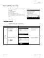
Starting up the ultracentrifuge
Before setting run conditions, display the run screen (screen for setting run conditions)
(1) Displaying the Run Screen (screen for setting run conditions)
1. Turn on the POWER switch.
2. The initial screen appears.
Initial screen
3. The Run Screen appears.
Figure 2-1 Initial screen, and run screen
Thermo Scientific
WX Ultra Series
2-3
Operation
Basic operation
Preparing tubes/bottles and rotor
Within 5 mm
(0.197 in)
Within 5 mm
(0.197 in)
The Sorvall WX Ultra series ultracentrifuges allow you to balance, by eye, tubes or bottles containing a
sample solution and then centrifuge them. Make sure that the difference between meniscus levels of
sample solution in tubes or bottles in within 5 mm (0.197 in) (See fig. 2-2).
(2) Bottles
(1) Tubes
Figure 2-2 Balancing tubes/bottles containing a sample solution
To prevent tube or bottle failure, some tube and rotor combinations cannot be run to the maximum
speed of the rotor when partially filled. The tube or bottle must be full in the following cases:
1. When a thin tube or seal tube is used.
2. When a thick tube is used for swinging rotor.
3. When a bottle is used 100,000 x g or more.
Basic operation
WARNING
Do not lean on, tilt or place anything on the centrifuge while in operation.
CAUTION
1. Do not operate the keyboard with a ball-point pen or a sharp object.
2. Do not continue to operate the centrifuge if abnormal sounds occur during operation.
Immediately discontinue use of the centrifuge and contact Thermo Service.
Setting run conditions
This section will first describe the screen for basic operation (the run screen) and the cursor keys.
2-4
WX Ultra Series
Thermo Scientific
Operation
Basic operation
[run screen]
The screen for displaying run conditions and operational status is called the run screen.
Speed, time, and temperature are displayed in two rows: the top row displays the current actual run
conditions, while the bottom row displays the set run conditions.
The acceleration (ACCEL) and the deceleration (DECEL) fields display set conditions.
state
} Operation
display field
value
} Setting
display field
}
Run mode indicator
Figure 2-3 Run screen
[Cursor key]
Pressing the cursor key will highlight the field where changes can be made. (This blinking/highlighted
object is referred to as the cursor in this manual.)
The screen setting field is in either of the following states depending on whether the cursor is there.
1. Determined input state: This is a normal state and the cursor does not appear.
2. Input wait state: Press a cursor key (either the top, bottom, right, or left) while in the determined
input state, and the numerical part of the setting field will blink a 0 (or numerical value) and
display the cursor. In this state, the system accepts a numerical input. Press cursor keys to move the
cursor.
To set a run condition, enter the cursor into an input wait state, move the cursor to the item you want
to set, then enter a value. If you have made no keystroke (such as a numerical input) for more than 30
seconds, the system will automatically enter a determined input state.
Note When the screen is in a determined input state without a cursor (when the Run Screen is on
after power-up), if you wish to enter a numerical value in a specified parameter field, press a cursor
key (either of the upward, downward, right, and left arrow keys), move the cursor to the specified
parameter field, then enter the value.
The cursor keys display and move a cursor. Once a cursor appears, pressing a cursor key moves the
cursor to the corresponding direction (upward, downward, rightward, or leftward).
Thermo Scientific
WX Ultra Series
2-5
Operation
Basic operation
Cursor key
Cursor (blinking)
The system does not accept a
numerical input.
The system accepts a numerical input.
Use cursor keys to move to the next
setting item.
(2) Input wait state
(1) Determined input state
Figure 2-4 Setting indicator
Note
1. If you enter the wrong value, press CE key to return to the input wait state.
If you have pressed ENTER key, press a cursor key, enter the device into an input wait state,
then enter the correct value.
2. When setting two or more run conditions, you do not have to press ENTER key after each
setting. Pressing the cursor key will enter the setting, thus making the system wait for a new
input.
3. If the system is running in (HOLD) and you want to set it to shut down at a future time, enter
a new time setting while the instrument is in operation; enter the sum of the time elapsed plus
the time remaining. If, for example, this machine has run continuously for five hours and you
want to stop it one and a half hours later, use cursor keys to enter TIME into an input wait state,
then enter
How to set speed, running time, temperature, and other parameters
Here are some examples and descriptions:
2-6
Setting item
RPM (SPEED
Running time (TIME)
Typical setting
100,000 rpm
2 hours 30 minutes
WX Ultra Series
Thermo Scientific
Operation
Basic operation
1
Press cursor keys to enter the system into an
input wait state.
2
Use cursor keys to move the cursor to the
status indicator. (The arrows indicate the
directions the cursor can be moved..
The system enters an
input wait state.
2 hours 30 minutes
The system enters an
input wait state.
Arrow
The cursor in the setting item field blinks for
about 30 seconds.
Blinking means that the system enters an
input wait state.
4
Use numeric keys to enter a setting.
Operation procedure
3
The last two digits are
fixed.
Press the “
Set it to 100,000 rpm.
Set it to 2:30
(2 hours 30 minutes).
Can be set to any value in
the range from 1,000 rpm
to maximum speed in
increments of 100 rpm.
Can be set to any value
up to 99 hours 59 minutes
in increments of 1 minute.
move the cursor to the
“minutes” position.
For a continuous run,
press HOLD/FREE.
Entered numbers are moved to the left every
time a new number is entered.
5
Make a check, then press ENTER.
” key to
After pressing a cursor key, you can still
enter a setting similarly to the ENTER key.
Use CE to cancel an input.
Setting range and units
Temperature (TEMP)
4.5 °C
Enters an input wait state.
Thermo Scientific
Acceleration (ACCEL)
9
Enters an input wait state.
Deceleration (DECEL)
7
Enters an input wait state.
WX Ultra Series
2-7
Operation
Basic operation
The cursor blinks at one place.
FUNCTION field
For free coast, press HOLD/FREE.
Display: F
When one decimal place is not
required, you do not need to enter
. If you press
, it becomes
a “decimal place” input and the
machine waits for an input of decimal places.
Set it to 4.5 °C.
Set it to 9
Set it to 7.
• The FUNCTION field
switches to the ID CODE
field.
• The number of units of ID
CODE blinks.
Can be set to any value in the range
from 0 to 40 °C in increments of 0.1
°C.
1 to 9
1 to 9
+
free coast (F)
• The entered number is not
displayed on the screen. * is
displayed instead of the
number.
>> After the registered ID CODE is entered, the name (USER NAME) corresponding to
the ID CODE is displayed.
2-8
WX Ultra Series
Thermo Scientific
Operation
Basic operation
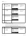
Setting user ID code
The USER ID CODE is a number to identify each user and can be set in up to 4 digits.
When the user ID CODE is entered, the user record will be stored in the memory of the centrifuge and
can be printed if a printout operation is done (optional).
Entering a user ID CODE may not be always required for operation (Lockout feature optional). If the
centrifuge is not equipped with the optional lockout feature and the user does not need to be
identified, the centrifuge can be operated without an ID CODE.
• To use a name (user name) corresponding to the user ID code or ID code, it must be registered.
For the registration method, see Section User list.
Step
Key operation
1
On the Run Screen, use cursor keys to
move the cursor to ID CODE and press
the ENTER key.
Screen display and considerations
• The display switches to the
rotor control field, which
displays the Rotor List
screen.
2
Use numeric keys to enter ID CODE
(4 digits).
(When entering 0123)
ID code
• The display switches back
to the Run Screen and
“T-8100-1234” is
displayed in the message
field.
3
Press the ESC key on the keyboard to
return to the FUNCTION field.
Thermo Scientific
WX Ultra Series
2-9
Operation
Basic operation
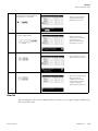
Using Rotor Life Management
The rotor type and serial number may be set in rotor management to allow for rotor logging within the
centrifuge. Whether the rotor type and serial number for a particular rotor have been set or not, it does
not affect the normal operation of the ultracentrifuge. However, you are advised to set the rotor type
and serial number of the rotor for each run to allow effective rotor life management. Any registered
rotor that does not have its rotor type and serial number set will appear as an undefined rotor in the
displayed list (“Undefined rotor 1”).
You can use a particular rotor as undefined if you need to manage the rotor separately from the other
defined rotors in terms of the number of runs made and accumulated run time (“Undefined rotor 2”).
For more information on rotor life management, see Section Rotor management.
Step
Key operation
1
On the Run Screen, use cursor keys to
move the cursor to RLM and press the
ENTER key.)
2
On the rotor control field, use the left
and right arrow keys
and
3
Screen display and considerations
to select each page.
Use the up and down arrow keys to
move the cursor to the row of the rotor
type to be used and press the ENTER
key.
In this example, the cursor moves to
“T-8100-1234”.
Select “Running”.
2-10
WX Ultra Series
Thermo Scientific
Operation
Basic operating procedure
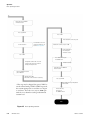
Basic operating procedure
There are two basic modes of operation, normal and zonal. The procedures for these two modes are shown in Fig. 2-5.
START
Zonal run
Turn on the POWER.
Open the chamber door and
install the rotor.
Normal run
Close the door and set the run
conditions.
For information on how to set
the run conditions, see
Section Basic operation
Reaches the set time,
or press STOP.
Rotor comes to a stop.
Press VACUUM.
Press VACUUM.
Temperature control is OFF.
Vacuum pump is OFF.
Air valve is open and door lock
is released.
Vacuum pump is ON.
Temperature control starts.
Check the set run conditions
for accuracy.
Remove the rotor and turn off
the POWER switch.
Press START.
Rotor accelerates to the set speed, and then
high-speed centrifugation begins.
END
: Indicates panel key.
Thermo Scientific
WX Ultra Series
2-11
Operation
Basic operating procedure
Move the cursor to ZONAL
in the Run Screen.
Press 3, 0, ENTER
Press START.
Rotor accelerates to the set speed.
Set run conditions.
For information on how to
set the run conditions, see
Section Basic operation.
Reaches the set time, or press STOP.
Rotor decelerates to
the zonal speed.
The buzzer sounds.
Press START.
Press VACUUM and open
the chamber door.
Temperature control starts. The rotor
rotates at the zonal speed. Load the
sample, then cap the rotor.
Unload the sample.
Move the cursor to ZONAL in
the Run Screen.
Close the chamber door and
press VACUUM.
Vacuum pump is ON.
Check the set run conditions for accuracy.
* This step may be skipped. Just press START to
run the ultracentrifuge. When START is pressed,
the vacuum pump turns on and the rotor begins
to accelerate. Then the rotor stays at 4000 rpm
until the rotor chamber reaches predetermined
vacuum level.
Press 0, 0, ENTER
Rotor comes to a stop. Temperature
control is OFF.
Remove the rotor,
then turn off
the POWER switch.
END
Figure 2-5 Basic operating procedure
2-12
WX Ultra Series
Thermo Scientific
Operation
Basic operating procedure
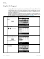
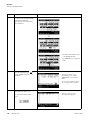
Normal operation
Given below is a description of the operational procedure for a normal run.
Speed
Note Before starting up this machine, carefully read the operation manual for your rotor and make
sure that you have selected the correct type of tubes and entered the correct amount of sample.
Time
Figure 2-6 Normal operation mode
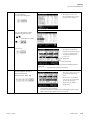
Step
Operation and keystrokes
Unit operation and considerations
1
Turn on the POWER switch on this machine.
>> The panel display lights up.
>> The door is unlocked.
2
Open chamber door and make sure chamber is
dry.
3
Install the rotor.
>> Before installation, read the rotor instruction manual carefully.
4
Set run conditions.
>> See Section Setting run conditions and set run conditions.
5
Press VACUUM key. (optional)
>> The machine starts evacuating the rotor chamber.
>> Temperature control starts.
>> The degree of vacuum in the rotor chamber is displayed on the vacuum indicator
on the display panel.
(1) In a low vacuum
(1 indicator)
(2) In an intermediate vacuum
(2 indicators)
(3) In a high vacuum
(3 indicators)
>> If the rotor compartment has moisture or frost on it, it takes a long time to reach
a high vacuum.
In that case, wipe it off with a clean, dry cloth or sponge.
>> If the sample is sensitive to a temperature rise, do not press the START key
until the chamber is at high vacuum level.
6
Press START key
Thermo Scientific
>> The rotor starts spinning.
>> The timer begins operating.
>> The rotor accelerates to the set speed.
>> This ultracentrifuge waits at 4,000 rpm until an intermediate vacuum is
reached.
WX Ultra Series
2-13
Operation
Basic operating procedure
7
The specified centrifugation time elapses
(time-out). Or press STOP key.
>> The rotor decelerates and stops.
8
The rotor brakes or coasts to a stop.
>> Beeps to indicate that the rotor has stopped.
9
Press VACUUM key.
>> The vacuum stops, the air leak valve gets activates, and the rotor chamber
reaches atmospheric pressure.
>> The door unlocks, and is able to be opened and closed.
10
Take out the rotor.
Speed (rpm)
The run mode indicator on the display panel displays the following:
Time
Figure 2-7 Displays of run modes
Note Use the vacuum key to avoid prolonged vacuum wait time at 4,000 rpm when the ambient
temperature is low.
2-14
WX Ultra Series
Thermo Scientific
Operation
Basic operating procedure
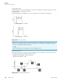
Zonal operation
Zonal operation is a mode of operation using a zonal rotor or continuous flow rotor for density
gradient centrifugation with large amounts of sample or continuous sedimentation of particles from a
large volume sample.
The following zonal rotors are available for operation in the Sorvall WX Ultra series ultracentrifuges:
TZ-28 sealed zonal rotor
TCF-32 continuous flow zonal rotor
The TZ-28 can only be operated in a sealed zonal mode. Dynamic loading/unloading or continuous
flow operation IS NOT allowed.
The TCF-32 zonal rotor can be operated in a continuous flow mode requiring dynamic loading and
unloading. The rotor comes with a kit to modify the Sorvall WX Ultra series.
The continuous flow zonal operation consists of the following three stages:
1. Centrifugation at low speed, called the zonal speed *, the gradient or sample being loaded in this stage.
2. Acceleration to set speed and separation of the sample, or
Speed
3. Centrifugation at zonal speed, the sample and or gradient being unloaded in this stage.
* Zonal speed
Time
Figure 2-8 Zonal operation mode
* Zonal speed: The zonal speed is one that is required for loading and unloading the sample.
The zonal speed is normally set at 3,000 rpm, but it can be set in the range from 2,000 to 3,000 rpm in
increments of 100 rpm to obtain the required speed. For details of how to change zonal speed, see
Section User Customizations.
WARNING
When operating the centrifuge with the door open and the rotor spinning,
eliminate all possibility of contact with the rotor. Remove any objects not essential to
operating procedures which could either catch on or drop into the spinning rotor (that is,
neckties, rings, bracelets, watches, long sleeves, or any loose articles in breast pockets).
The following explains how to perform a zonal run.
Step
Operation and keystrokes
Unit operation and considerations
1
Install the zonal rotor on the drive spindle.
>> See zonal rotor manual.
Thermo Scientific
• The characters ZONAL
are displayed in the
message display field on
the screen and the zonal
operation mode is set.
WX Ultra Series
2-15
Operation
Basic operating procedure
2
On the Run Screen, move the cursor to ZONAL
and enter the following by operating numeric
keys to set the zonal operation mode.
• Rotor begins to accelerate
to the zonal speed.
• Temperature control
begins.
3
Set the run conditions.
4
Press the START key.
>> For details, see Section Basic operation.
Note The time being consumed at zonal speed is not counted as
part of the run.
5
Install the seal assembly on the rotor.
>> For details, see zonal rotor manual.
6
Load the sample and the gradient solution.
7
Install the cap assembly on the rotor.
8
Close the chamber door.
9
Press the VACUUM key. (This step may be omitted.)
>> Vacuum pump begins to work.
>> Chamber door is locked.
10
Press the START key again.
>> Rotor begins to accelerate to the set speed.
Note The run time is counted from when the START key is pressed. The
instrument can also count only the time elapsing while the rotor is
spinning at high speed. This is possible by changing the run time setting
range. For details, see Section “Run time range setting” on page 2-80.
11
If you need to stop the run before the set time
elapses, press the STOP key.
>> Rotor is decelerated to the zonal speed and then the buzzer sounds.
12
Press the VACUUM key.
>> Vacuum pump stops working and air enters the rotor chamber.
>> Door lock is released.
2-16
WX Ultra Series
Thermo Scientific
Operation
Acceleration and deceleration rates
13
Open the chamber door.
14
Remove the cap assembly
15
Install the seal assembly and unload the sample.
16
On the Run Screen, move the cursor to ZONAL
in the FUNCTION field and enter the following
by operating numeric keys to set the normal
operation mode.
>> For details, see zonal rotor manual.
>> Rotor decelerates to a stop.
Note During the zonal mode, the rotor will not decelerate even if the
STOP key is pressed during the rotor's spinning at the zonal sped.
17
Be sure that the rotor is at rest, then remove the
rotor.
>> If the rotor is still spinning, do not remove it. Wait until it comes to a complete
stop.
Note By changing to the NORMAL mode when loading and unloading the sample, you can
decelerate the rotor to a stop.
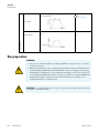
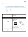
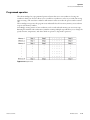
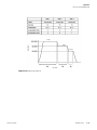
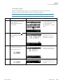
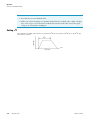
Acceleration and deceleration rates
In order to meet various experimental protocols, the acceleration and deceleration rates can be adjusted
between 0 to 500 rpm.
The figure and table below show the relationship between ACCEL/DECEL code numbers selected and
resulting approximate acceleration/deceleration times.
Speed (rpm)
ACCEL/DECEL code numbers
Time
Thermo Scientific
WX Ultra Series
2-17
Operation
Acceleration and deceleration rates
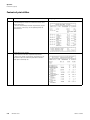
Code No.
Acceleration time (minutes) from rest to
500 rpm
Deceleration time (minutes) from 500
rpm to rest
9
Minimum time*
Minimum time*
8
1
1
7
2
2
6
3
3
5
4
4
4
5
5
3
6
6
2
7
7
1
8
8
F
-
Coasting deceleration
* Minimum time is the time for accelerating or decelerating by the driving motor with maximum
torque. this time depends on the type of rotor in use.
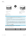
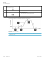
The following are typical examples of application of acceleration and deceleration rates
Suggested code nos.
ACCEL
DECEL
Characteristic of separation
Density gradient centrifugation
using a vertical rotor
5
7
The sample and gradient in tubes reorient during acceleration and deceleration. Therefore, the sample and
gradient can become mixed, especially in wide tubes, if
you use rapid acceleration or deceleration.
DNA separation by CsCl isopycnic separation (self-forming
gradients)
9
7
You can operate at maximum acceleration because the
density gradient is not formed during the run. As for the
deceleration, it is better to decelerate slowly to obtain
sharp bands.
Pelleting using a fixed angle
rotor
9
9
Rapid pelleting of samples is possible (the run time
decreases).
Density gradient centrifugation
using a swinging bucket rotor
8
8
The sample and gradient do not reorient. Therefore,
mixing of the layers is less than that in the case of using
a vertical rotor.
Note For a swinging bucket, there is no difference with regard to turbulence if ACCEL/DECEL is
less than or equal to 8. However, when the mode for long acceleration time is selected, (1, 2, 3), an
imbalance alarm indicator may light.
2-18
WX Ultra Series
Thermo Scientific
Operation
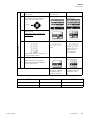
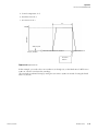
How to use the FUNCTION field
Speed
Allowable maximum speed
500 rpm
2 minutes
15 minutes
15 minutes
2 minutes
Figure 2-9 Operation with setting ACCEL = 0 and DECEL = 0
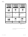
How to use the FUNCTION field
This ultracentrifuge incorporates a number of features. These features are displayed and specified in the
FUNCTION field.
The FUNCTION field is extended as shown in the following figure.
ENTER key
ENTER key
Figure 2-10 FUNCTION field
Thermo Scientific
WX Ultra Series
2-19
Operation
How to use the FUNCTION field
ID CODE:
Sets an ID code.
RLM:
Switches the Run Screen to the rotor management field.
PROG:
Programs, stores, and recalls run conditions. This feature
also offers a step-mode operation: a continuous run of
multiple run conditions.
RTC:
Sets a start time or a finish time and runs the ultracentrifuge
at a desired date and time.
RCFmax:
Maximum centrifugal force for the maximum radius rmax of
the rotor used. This feature is used to cause the system to
automatically calculate and display RCFmax. It also sets an
RCFmax value and calculates the speed.
RCFavg:
Causes the system to automatically calculate and display the
average centrifugal force RCFavg for the average radius ravg
of the rotor used. It also sets an RCFavg value and calculates
the speed.
ω2T:
Performs an rω2T run and arithmetic operations.
DEF:
Turns on and off the defroster.
ZONAL:
Selects between zonal operation and normal operation.
Figure 2-11 Rotor radius
The above features can be used in combination.
When all settings are entered, press ESC to move back to the Run Screen. Then enter a setting for
another feature to form a combination.
Note To perform a combination of PROG and RTC, first set PROG and then set RTC. Once
RTC is activated, you cannot change the run time. You therefore cannot activate PROG.
2-20
WX Ultra Series
Thermo Scientific
Operation
How to use the FUNCTION field
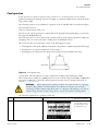
Programmed operation
This ultracentrifuge has a programmed operation feature that stores run conditions. Storing run
conditions which you often use allows you to recall those conditions as often as you wish, thus saving
time in setting. (The saved run conditions will remain in effect even after the power switch is turned
off.)
This centrifuge incorporates the program areas indicated below. It has twenty memory areas and nine
steps in each memory number.
Accordingly, twenty patterns of run conditions can be stored and each memory can store nine steps.
Running this machine with each memory number retaining multiple steps will allow you to change the
speed, run time, temperature, and others while in operation. (Step-mode operation).
Figure 2-12 Program areas
Thermo Scientific
WX Ultra Series
2-21
Operation
How to use the FUNCTION field
Basic operation of the programmed operation feature
Use cursor keys
to
select
and
ENTER key
press ENTER key.
Use cursor keys
select
to
and
ENTER key
If you know which memory number
stores the run condition.
press ENTER key.
Enter a memory
number.
To store, change or delete a
program, or if you have forgotten
the memory number where the run
conditions are stored.
ENTER key
Press
key to cause
to blink and
press ENTER key.
Programmed operation
possible
Enter a desired memory number and
press ENTER key.
Memory unit number
ENTER key
Press ESC several times to go
back to the Run Screen.
Next page
2-22
WX Ultra Series
Thermo Scientific
Operation
How to use the FUNCTION field
Note You cannot create, change, or delete a program while in running. Perform these operations
while not in running. However, you can search the memory screen every time.
Thermo Scientific
WX Ultra Series
2-23
Operation
How to use the FUNCTION field
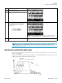
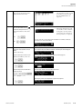
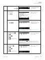
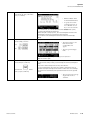
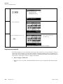
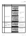
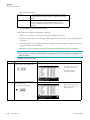
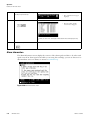
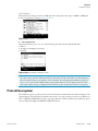
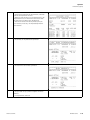
1. Programming procedure for run conditions (creating or changing)
Shown below is the procedure for storing (creating) or changing a run condition.
Step
Key operation
1
While in the Run Screen, use the cursor keys to move the cursor to PROG •
RTC and press ENTER key.
Then, move the cursor to PROG and
press ENTER key.
Screen display and considerations
• The FUNCTION field
switches to the PROGRAM
field.
• The MEMORY No. setting
field blinks.
2
Press the upward cursor key
to
cause PROGRAM to blink, then press
ENTER key.
• The display switches to the
Program Map screen and the
MEMORY No. selection
field blinks.
>> If you wish to store a new condition, enter it into an empty memory number.
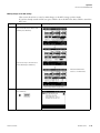
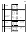
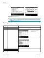
3
4
Use numeric keys to enter a memory
number you wish to store (or change).
Example: To store a condition in memory number 3, press
• The memory screen you
have just specified appears.
Select “Creating or Changing.”
• The message field in the bottom
row switches to what is shown in
the figure to the left.
2-24
WX Ultra Series
Thermo Scientific
Operation
How to use the FUNCTION field
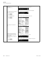
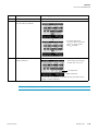
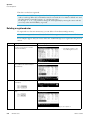
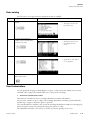
5
6
Enter a desired condition.
For example, select “SPEED”.
Select a desired rotor.
To select a desired rotor from the
“Used Rotor List”:
• The display switches to the
Choose Rotor screen.
• The display switches to the Used
Rotor List screen.
• You can search for the rotor
number you need in the order
starting with the latest date/time.
To select a desired rotor from the
“Rotor Catalog”:
(1) Select “Rotor Catalog”.
• The display switches to the Select
Rotors screen.
(2) Select Fixed Angle Rotor in the rotor
types.
(When using fixed angle rotor T-880)
• The display switches to the Fixed
Angle Rotor list screen.
(3) Select fixed angle rotor T-880.
• The specifications of the T-880
are displayed.
(4) Select “Yes”.
Thermo Scientific
WX Ultra Series
2-25
Operation
How to use the FUNCTION field
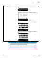
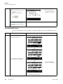
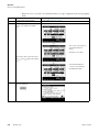
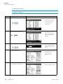
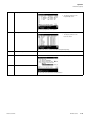
6
To select a desired rotor from the
“Rotor Management”:
(1') Select “Rotor Management”.
• The display switches to the Rotor
Management screen and the
Rotor List is displayed.
(2') Select a desired rotor using the
upward or downward cursor key
.
(When using fixed angle rotor T-8100)
(3') Select “Yes”.
• The rotor type you have just
entered appears in the top row in
the screen.
• The SPEED field in the SPEED
priority screen blinks.
To select no rotor:
Select “None”.
7
Enter values into SPEED (RCFmax or
RCFavg or ω2T), TIME, TEMP, A
(ACCEL), and D (DECEL).
Example
(Downward cursor key)
2-26
• The SPEED field in the SPEED
priority screen blinks.
WX Ultra Series
• When you finish entering run
conditions for step 1, step 2 enters
into an input wait state.
>> To enter run conditions in multiple steps in a step-mode operation, continue
the operation from the above. (See Section Step-mode operation.)
>> You cannot skip a step. (You cannot enter anything in step 2 with nothing
entered into step 1.)
Thermo Scientific
Operation
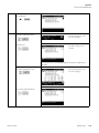
How to use the FUNCTION field
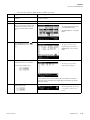
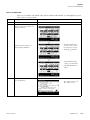
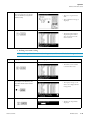
To change a run condition, use cursor
keys to move to the item you want to
change and then enter a value.
8
Press the downward cursor key
to blink the value part of the message
field in the bottom row. Then select
“Yes”.
• This diagram shows what you will
get if you move the cursor and
enter the TIME field into an
input wait.
>> If you select “Yes”:
• The message field in the bottom
row switches to what is shown in
the diagram to the left, and the
storing of the run conditions in
memory number 3 is completed.
Yes
>> If you select “No”, the message field in the bottom row switches to what you
see in process 4. Select a new setting.
No
9
After entering memory run conditions,
perform an entry operations for User
Name.
(1) Press the ESC key.
>> When you press ESC key, the bottom row message is displayed.
(1) A selection field as to whether User Name should be input or deleted appears.
(2) When attaching User Name to the
memory run conditions, select “Yes”.
(2) A selection field for selecting either inputting or deleting appears.
(3) Select “Inputting User Name”.
(3) The display switches to the ID CODE input field.
(4) Enter 4 digits of the ID CODE that is
already registered.
(4) The display switches to the User Name check field.
ID code
(5) Check User name and select “Yes”.
Thermo Scientific
(5) The display switches to the Registration completion message field.
WX Ultra Series
2-27
Operation
How to use the FUNCTION field
10
Add Remark to the run conditions in
the memory.
(1) Press the ESC key.
>> When you press ESC key, the bottom row message is displayed.
(1) A selection field to input or delete Remark appears.
(2) A selection field to select either inputting or deleting appears.
(2) To add Remark to the run conditions
in the memory, select “Yes”.
(3) Select “Inputting Remark”.
(3) The display switches to the Remark registration field.
(4) Enter Remark in 8 characters or
less.
(4) Remark is entered from the left.
(5) After entering the characters for
Remark, move the cursor to SET and
press the ENTER key to register the
character string.
(6) Check the contents of Remark and
select “Yes”.
(5) The display switches to the Remark check field.
(6) The display switches to the registration completion message field.
2-28
WX Ultra Series
Thermo Scientific
Operation
How to use the FUNCTION field
11
When the storing is over, press ESC
key several times.
>> The first push on ESC key switches the message display in the bottom row to
what you see in process 3 as shown below. To run this centrifuge, select Running.
>> Pushing ESC key a second time displays the Program Map screen shown in
process 3.
• Make sure that the condition is
stored in memory number 3.
>> The third push on ESC key switches you back to the Run Screen (program
screen).
>> The fifth push on ESC key switches you back to the Run Screen (FUNCTION
field).
Note
1. If you make and store changes in a memory area that already stores run conditions, the
previous conditions are replaced by the new conditions.
2. You cannot store a run condition while running (while the rotor is spinning). Always
perform this function while not running.
Thermo Scientific
WX Ultra Series
2-29
Operation
How to use the FUNCTION field
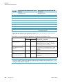
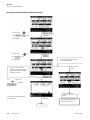
2. How to perform a programmed operation
Shown below is how to perform a “programmed operation”, that is, how to recall a stored set of run
conditions and run this centrifuge accordingly.
(a) If you know which memory unit number you need
Step
Key operation
Screen display and considerations
1
Turn on the POWER switch on the centrifuge.
>> The panel display appears.
>> The door unlocks.
2
Install a rotor.
>> Install the rotor securely on the shaft.
3
While in the Run Screen, use cursor
keys to move the cursor to PROG • RTC
and then press ENTER key.
Next, move the cursor to PROG and
press ENTER key.
4
• The FUNCTION field switches
to the PROGRAM field.
• The MEMORY No. setting field
blinks.
Enter the memory number you wish to
operate.
• The run conditions in memory
appear in the respective fields.
Example: to call memory number 3,
press
>> The message field in the bottom row displays PROG.
>> If the STEP field displays what is shown below, this means that the memory
unit you have just called stores multiple run conditions (stepmode feature). For
details, see Section Step-mode operation.
In the Run Screen, the run conditions of
this step are displayed (the first step
in this case).
Final step
>> The system only accepts numbers 1-20.
5
2-30
Run the centrifuge under normal operation without making changes to the
run conditions.
WX Ultra Series
>> Run this machine according to Normal operation.
>> If you make changes to the run conditions (such as SPEED and TIME) after calling a program, the program you have just called is canceled. You must call it
again to use it.
Thermo Scientific
Operation
How to use the FUNCTION field
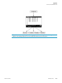
(b) If you do not know which memory number you need
Step
Key operation
Screen display and considerations
1
Turn on the POWER switch of this
machine.
>> The panel display appears.
>> The door unlocks.
2
Install a rotor.
>> Install the rotor securely on the shaft.
3
While in the Run Screen, use cursor
keys to move the cursor to PROG • RTC
and then press ENTER key. Then, move
the cursor to PROG and press ENTER
key.
4
5
Press the upward cursor key
to
blink PROGRAM. Then press ENTER
key.
• The FUNCTION field switches
to the PROGRAM field.
• The MEMORY No. setting field
blinks.
• The display switches to the
Program Map screen and the
MEMORY No. selection field
blinks.
Use numeric keys to enter the memory
number where you have stored data.
To call memory number 3, press
• The image of the specified
memory number appears.
>>If the contents of the memory number you have just recalled is not what you
want, press ESC to switch back to the Program Map screen and then call another
memory unit number.
6
If you get the memory number you
want, select Running.
• The message field in the bottom
row switches to what you see
below.
Thermo Scientific
WX Ultra Series
2-31
Operation
How to use the FUNCTION field
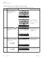
7
To run the centrifuge, select “Yes”.
>> If you select “Yes”
• The display switches back to the
Run Screen.
Yes
• The run conditions in memory
appear in the respective fields.
>> The message field in the bottom row displays PROG.
>> If the STEP field displays what is shown in the figure below, that means that
the memory number you have just called stores multiple run conditions
(step-mode feature). For details, see Section Step-mode operation.
In the Run Screen, the run conditions of
this step are displayed (the first step in
this case).
Final step
No
>> If you select “No”, the message field in the bottom row displays what you see
in process 5. Select a new condition.
8
Start running the centrifuge under normal operation with no changes made
to the run conditions.
>> Run this machine according to Section Normal operation.
>> If you make changes to the run conditions (such as SPEED and TIME) after
recalling a program, the program you have just recalled will be canceled. You
must recall the program again to use it.
Note
1. To check the contents (run conditions) of the memory number for the program while in
running, follow processes 3 through 5 in (b) “If you do not know which memory unit number
you need.” After the check, press ESC to get back to the Run Screen.
2. To perform a combination of a programmed run with RTC (real-time control) (see Section
RTC (real-time control) feature), first recall a programmed memory number, then set RTC.
The system will then calculate the total of the running times of all steps of the programmed
run and calculate the start time for RTC. Therefore, you cannot recall the program memory
after setting RTC.
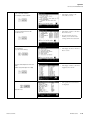
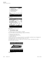
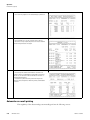
Step-mode operation
This ultracentrifuge incorporates a step-mode operation feature, which stores two or more run
conditions in one program memory area and switches between different values of speed, running time,
temperature, and other parameters while in operation. This centrifuge can store up to nine steps.
This section explains how to make settings by showing some examples.
(1) How to activate a step-mode operation
[Typical settings]
Shown below is the example of a three-step run and how to activate a step-mode operation.
2-32
WX Ultra Series
Thermo Scientific
Operation
How to use the FUNCTION field
Step 1
Speed (rpm)
Step 2
Step 3
Run time
Figure 2-13 A typical step-mode run
Thermo Scientific
WX Ultra Series
2-33
Operation
How to use the FUNCTION field
Step
Key operation
1
While in the Run Screen, use the cursor keys to move the cursor to PROG •
RTC and press ENTER key.
Then move the cursor to PROG and
press ENTER key.
Screen display and considerations
• The FUNCTION field switches
to the PROGRAM field.
• The MEMORY No. setting field
blinks.
2
Press the upward cursor key
to
cause PROGRAM to blink, then press
ENTER key.
• The display switches to the
Program Map screen and the
MEMORY No. selection field
blinks.
• To store a new condition, enter it
into an empty memory number.
3
Use numeric keys to enter the memory
unit number you want to store.
To store data in memory number 3,
press
2-34
WX Ultra Series
• The image of the specified
memory number appears.
Thermo Scientific
Operation
How to use the FUNCTION field
4
Select “Creating or Changing.”
• The message field in the bottom
row switches to what you see on
your left-hand side.
5
Enter a desired condition.
To select SPEED, press
• The display switches to the
Choose Rotor screen.
To select no rotor, press.
• The display switches to the
SPEED priority setting field and
the SPEED area blinks.
>> To select and enter RCFmax or RCFavg, see Section 1. Programming procedure for
run conditions (creating or changing)
6
Specify run conditions for step 1.
• The entry of run conditions for
step 1 is complete.
Downward cursor key
>> If you press the cursor key
(downward) after setting numeric value for
DECEL (D) in step 1, setting the run conditions in step 1 finishes and step 2 enters
into an input wait state.
7
Then specify run conditions for step 2.
• The entry of run conditions for
step 2 is complete.
Downward cursor key
Thermo Scientific
WX Ultra Series
2-35
Operation
How to use the FUNCTION field
8
Lastly, specify run conditions for step
3.
• The entry of run conditions for
step 3 is complete and step 4 is
ready for input.
Downward cursor key
9
Press the downward cursor key
to blink the value part of the message
field in the bottom row. Then select
“Yes”.
If you select “No”, the message field
in the bottom row switches to what
you see in process 4. Input a new
setting.
Yes
No
10
>> If you select “Yes”:
After entering step-mode run conditions, perform an entry operations for
User Name.
>> When you press ESC key, the bottom row message is displayed.
(1) A selection field as to whether User Name should be input or delete appears.
(1) Press the ESC key.
(2) When attaching User Name to the
memory run conditions, select “Yes”.
(3) Select “Inputting User Name”.
(4) Enter 4 digits of the ID CODE that is
already registered.
(2) A selection field for selecting either inputting or deleting appears.
(3) The display switches to the ID CODE input field.
(4) The display switches to the User Name check field.
ID code
(5) The display switches to the Registration completion message field.
(5) Check User Name and select “Yes”.
2-36
WX Ultra Series
Thermo Scientific
Operation
How to use the FUNCTION field
11
Add Remark to the run conditions in
the memory.
(1) Press the ESC key.
>> When you press ESC key, the bottom row message is displayed.
(1) A selection field to input or delete Remark appears.
(2) To add Remark to the run conditions
in the memory, select “Yes”.
(2) A selection field to select either inputting or deleting appears.
(3) Select “Inputting Remark”.
(3) The display switches to the Remark registration field.
• The message field in the bottom
row switches to what is shown in
the diagram on your lefthand
side, and the storing of the run
conditions in the appropriate
memory number is completed.
(4) Enter Remark in 8 characters or
less.
(5) After entering the characters of
Remark, move the cursor to SET and
press the ENTER key to register the
character string.
(6) Check the contents of Remark and
select “Yes”.
12
Press ESC key when the storing is over.
13
Select “Running”.
Thermo Scientific
(4) Remark is entered from the left.
(5) The display switches to the Remark check field.
(6) The display switches to the registration completion message field.
WX Ultra Series
2-37
Operation
How to use the FUNCTION field
14
To run the centrifuge, select Yes.
>> If you select “Yes”:
• The display switches back to the
Yes
Run Screen.
• The run conditions of step 1 in
memory appear in the respective
fields.
>> The message field in the bottom row displays PROG.
15
No
>> If you select “No”, the message field in the bottom row displays what
you see in process 10. Make the selection again.
Start running the centrifuge under normal operation with no changes made
to the operational conditions.
>> Run the centrifuge according to Normal operation.
>> If you make changes to the run conditions (such as SPEED and TIME) after calling a program, the program you have just called gets canceled. You must call the
program again.
>> Pressing START makes the rotor rotate under the run condition of step 1.
>> When step 1 ends, the system moves to steps 2 and 3 automatically.
1. Step display
The PROGRAM field displays steps as follows:
In the Run Screen, the run
conditions of this step are
displayed (step 1 in this case).
Final step
When the system finishes separating step 1 and moves to step 2,
When the system moves from step 2 to the final step 3,
Thus, you can see at a glance how many steps are stored in the specified memory and which step the
centrifuge is following.
2. While the instrument is running (while the rotor is spinning), you cannot store a stepmode run
condition. Always perform this function while not in running.
3. To check the contents (run conditions) of a step-mode program memory number, follow processes
1 through 3. To get back to the Run Screen after the check, press ESC key.
4. To perform a combination of a step mode run with an RTC (real-time control) run (see Section
RTC (real-time control) feature), call a program memory number, then set RTC.
The system then calculates the total of running times of all steps of the programmed run and
calculates the startup time for RTC. You therefore cannot call a program memory number after
setting RTC.
2-38
WX Ultra Series
Thermo Scientific
Operation
How to use the FUNCTION field
(2) Deleting a program
This section explains how to delete a set of run conditions stored in program memory.
To delete a memory number, delete all steps in that memory number.
Note While the instrument is running, you cannot delete a program memory number.
Step
Key operation
1
While in the Run Screen, use cursor
keys to move the cursor to PROG • RTC
and press ENTER key.
Then move the cursor to PROG and
press ENTER key.
2
3
Press the upward cursor key
to
cause PROGRAM to blink, then press
ENTER key.
Use numeric keys to enter the memory
unit number you want to delete.
To delete memory unit 3, press
4
Screen display and considerations
• The FUNCTION field switches
to the PROGRAM field.
• The MEMORY No. setting field
blinks.
• The display switches to the
Program Map screen and the
MEMORY No. field blinks.
• The image of the memory unit
you have just specified appears.
Select “Deleting”.
• The message field in the bottom
row switches to what you see on
your left.
Thermo Scientific
WX Ultra Series
2-39
Operation
How to use the FUNCTION field
5
To delete this memory number, select
Yes.
Yes
>> If you select “Yes”.
• The system deletes all run
conditions in memory number 3.
(While in step mode, all steps get
deleted.)
No
>> If you select “No”, the screen switches to what you see in process 3. Make the
selection again.
6
Press ESC several times to move back
to the Run Screen.
>> If you delete a memory number, you can no longer run the centrifuge according
to that number.
(3) Other procedures
1. Making changes to the run conditions
Call the memory number you want to make changes to and make the changes. Alternatively, delete
the memory number, then store a new set of run conditions.
To make a change that will result in fewer steps, delete the memory number and then enter a new
set of run conditions and store them.
While in a programmed run, modification of a run condition is limited to the step which is
currently running.
2. Running the centrifuge starting from an intermediate step
You cannot run the centrifuge starting from an intermediate step in a memory number that
contains multiple steps.
Store (register) run conditions for the intermediate step and later steps in another memory
number. Then recall the memory number and run it.
3. What if a “SPEED” alarm goes on?
If a step stores a speed exceeding the maximum allowable speed of your rotor, the system will detect
it in the step 1 run and display the “SPEED” alarm.
Double-check the speed of all steps and correct any wrong ones.
4. Stopping the centrifuge in operation
Press STOP. The rotor stops and the system does not move to the next step.
RTC (real-time control) feature
The Sorvall WX Ultra series ultracentrifuges contain an internal clock, allowing you to run the
machine at a specified start or finish time for centrifugation. This feature for running the machine at a
specified time is called the RTC (real-time control) feature.
Below is an example of how to perform an RTC run.
Example: If you wish to install your rotor on the centrifuge under the run conditions listed below on
the evening of October 1 and take the samples out around 9:30 a.m. the next morning;
1. Rotor: T-8100
2. RPM: 100,000 rpm
3. Separation time: 4 hours
2-40
WX Ultra Series
Thermo Scientific
Operation
How to use the FUNCTION field
4. Control temperature: 4 °C
5. Acceleration mode: 9
6. Deceleration mode: 7
4h
Speed (rpm)
100,000
START key ON
4:30 p.m, October 1
Automatic start at 5:30 a.m., October 2
Stop around 9:34 a.m.
Finish time
9:30 a.m.
Figure 2-14 A typical RTC run
In this example, you set the above run conditions (2) through (6), set the finish time for RTC run to
9:30 a.m., October 1 and start the centrifuge.
(You can make an identical setting by setting the start time to 5:30 a.m. instead of setting the finish
time to 9:30 a.m.)
Thermo Scientific
WX Ultra Series
2-41
Operation
How to use the FUNCTION field
1. How to perform an RTC run
Step
Key operation
1
Screen display and considerations
Set operational conditions while in the
Run Screen.
Use cursor keys to enter the SPEED
part into an input wait, then press
Move the cursor to PROG • RTC and
press ENTER key.
2
3
Move the cursor to RTC and press
ENTER key.
Select the item you wish to set. To
select the “Setting stop time”, press
• The display switches to the
RTC Setup screen.
>> Setting the “Setting stop time”
• The “dd” item blinks.
“mm” and “dd” indicate the
current date as a default.
>> Setting the “Setting start time”
• If you do not make any
input for 30 seconds, the
cursor disappears, and you
cannot make an input. At
that time, press a cursor key.
2-42
WX Ultra Series
Thermo Scientific
Operation
How to use the FUNCTION field
4
Use cursor keys and numeric keys to
enter month, day, hours, and minutes.
Then, press ENTER key.
• Blink the PROG • RTC
in the FUNCTION field.
• To specify the run time
(centrifugation time), do
not set HOLD. Use ten
keys to enter the run time
instead.
>> To set the hours, use a number between 0 and 23 (in
the 24-hour system).
>> Enter a time later than the current time.
When setting the “Setting stop time”, allow for centrifugation time and set the
centrifugation start time to a time later than the current time.
>> You cannot set the centrifugation start time to a date more than 20 days
ahead.
5
If you are sure that you have made the
correct settings, select Yes.
Yes
No
>> If you select “Yes”
• The display switches to the
Run Screen and the
specified RTC time
appears.
• The message field displays
RTC.
>> If you select “No”, you will get the display you see in process 2.
Make the selection again.
6
Check the RTC setting in the Run
Screen, then press START key.
The RTC run does not get activated
unless you press START key.
>> Run this machine according to Section Normal operation.
>> Once the RTC setting is made, you cannot change the run time (centrifugation
time).
If you wish to make a change to the run time, cancel RTC first.
>> Pressing START enters the system into a “DELAY” (and vacuum comes on),
condition causing the centrifuge to wait until the set time comes. This centrifuge
will turn the rotor automatically at the specified time and run it for the specified
period.
• The run mode in the message
display field switches to
“DELAY”.
Thermo Scientific
WX Ultra Series
2-43
Operation
How to use the FUNCTION field
Speed (rpm)
1. For an RTC run, the run mode indicator on the display panel displays the following:
START key ON
Time
Automatic start
Figure 2-15 Run mode display (RTC)
2. You cannot make an RTC setting in any of the following cases:
a. When the Run Screen is set to HOLD (continuous run)
Set the run time (centrifugation time) not to HOLD but to a numerical value.
b. When it is past the start time
Set the start time to a time later than the current time.
c. When the start time is more than 20 days after the current time
Set the time to a time no more than 20 days afterwards.
3. To change the run time (centrifugation time) after making an RTC setting, cancel RTC and then
set a new run time.
4. To perform a combination of a programmed operation (including a step-mode operation) with an
RTC run, call a program memory number, then set RTC.
The system calculates the total run times of all steps of the programmed operation and calculates
the start time for RTC.
Therefore, you cannot recall the program memory number after setting RTC.
5. To stop this ultracentrifuge in RTC operation, press STOP key. The system then stops RTC and
stops the rotor.
2-44
WX Ultra Series
Thermo Scientific
Operation
How to use the FUNCTION field
Making changes to the RTC settings
This section shows how to cancel or make changes to the RTC settings you have made.
If you have already started an RTC run, press STOP to abort the RTC first. Press STOP to cancel the
RTC run.
Step
Key operation
1
(1) While in the Run Screen, use cursor
keys to move the cursor to PROG • RTC
and then press ENTER key.
Screen display and considerations
(2) Use cursor keys to move the cursor
to RTC and then press ENTER key.
• The FUNCTION field
switches to the RTC field.
>> The message indicator displays RTC.
2
Press cursor keys to blink RTC and then
press ENTER key.
Thermo Scientific
WX Ultra Series
2-45
Operation
How to use the FUNCTION field
3
Making a change to date and time settings
(1) Select “Setting stop time” or “Setting start time”.
To change the “Setting stop time”,
press
(2) Perform process 4 and later ones in
1. How to perform an RTC run mentioned above and change the date and
time settings.
• The screen switches to a
screen where you can enter a
stop time (or start time).
See Section 1. How to perform an RTC run.
Canceling the RTC settings
The canceling procedure varies depending on whether the RTC run is started (START is pressed) or
not.
Step
Key operation
1
(1) While in the Run Screen, use cursor
keys to move the cursor to PROG • RTC
and then press ENTER key.
Screen display and considerations
(2) Use cursor keys to move the cursor
to RTC and then press ENTER key.
• The FUNCTION field
switches to the RTC field.
>> The message indicator displays RTC.
2-46
WX Ultra Series
Thermo Scientific
Operation
How to use the FUNCTION field
2
Press cursor keys to blink RTC and then
press ENTER key.
3
[Before starting the RTC run]
(1) Select “Deleting the set RTC”.
• The message indicator in the
bottom row changes.
>>If you select “Yes”
(2) Select “Yes”.
• The RTC setting has been
canceled.
>> If you select “No”, you will get the display you see in process 2. Make a selection again.
[After starting the RTC run]
(1') Select “Deleting the set RTC”.
• The message indicator in the
bottom row changes.
(2') i) Select “Cancel RTC-NO run”.
Thermo Scientific
WX Ultra Series
2-47
Operation
How to use the FUNCTION field
ii) Select “Cancel RTC-Start run”.
iii) Select “Continue RTC”.
• The display switches back to
the Run Screen.
(3) Press ESC after process (2') i) or ii).
>> The RTC in the message indicator in the bottom row disappears.
Displaying and setting RCF
This ultracentrifuge stores the maximum and average radii of each rotor in internal memory. Setting a
speed causes this centrifuge to automatically calculate and display the RCF (relative centrifugal force)
value, while setting an RCF value causes the centrifuge to automatically calculate and display the speed.
Given below is a description of how to display and set RCF.
1. How to display an RCF value
• When the rotor to be used is already identified (when rotor type is displayed in the message display
field)
2-48
WX Ultra Series
Thermo Scientific
Operation
How to use the FUNCTION field
Step
Key operation
Screen display and considerations
1
While in the Run Screen, set a speed.
>> See Section Setting run conditions.
2
Use cursor keys to move the cursor to
RCF • ω2T and press ENTER key.
• The FUNCTION field
switches to what is shown in the
diagram to the left, and the
RCFmax field blinks.
3
Move the cursor to RCFmax (or RCFavg)
and press ENTER key.
• The RCF display field displays
the RCF value of the rotor.
RCF display field
RCF setting field
>> The RCF value associated with the set speed you have just entered in process
1 appears in the RCF setting field.
Note Press ESC key to cancel the RCF field.
Thermo Scientific
WX Ultra Series
2-49
Operation
How to use the FUNCTION field
• When the rotor to be used is not identified (when rotor type is displayed in the message display
field)
Step
Key operation
Screen display and considerations
1
Set the speed on the Run Screen.
>> See Section Setting run conditions.
2
(1) Use cursor keys to move the cursor
to RCF • ω2T and press the ENTER
key.
• The contents of the display in
the FUNCTION field
change.
• The RCFmax area blinks.
(2) Use cursor keys to move the cursor to
RCFmax (or RC Favg) and press the ENTER
key.
• The FUNCTION field
switches to the RCF field.
• ROTOR LIST blinks.
3
2-50
Check that ROTOR LIST blinks and
press the ENTER key.
WX Ultra Series
Thermo Scientific
Operation
How to use the FUNCTION field
4
Select a desired rotor. To select a
desired rotor from the “Used Rotor
List”:
• The display switches to the
Used Rotor List screen.
• You can search for the rotor
number you need in the
order starting with the
latest date/time.
To select a desired rotor from the
“Rotor Catalog”:
(1) Select “Rotor Catalog”.
• The display switches to the
Rotor List screen.
(2) Select Fixed Angle Rotors in the
rotor types.
(When using fixed angle rotor T-890)
• The fixed angle rotor list is
displayed.
(3) Select fixed angle rotor T-890.
• The specifications of the
T-890 rotor are displayed.
• The display switches to the
Choose Rotor screen.
4
(4) After checking the specifications of
the rotor, select “Yes”.
>> When you select “Yes”
• The display switches back
to the Run Screen and the
selected rotor type is
displayed in the message
display field of the bottom
row.
RFC display field
• The RCF value of the running rotor is displayed in the RCF display field.
>> When you select “No”, the display goes to the same as the display of process
4 (2).
Thermo Scientific
WX Ultra Series
2-51
Operation
How to use the FUNCTION field
4
To select a desired rotor from the
“Rotor Management”:
(1') Select “Rotor Management”.
• The display switches to the
Rotor Management screen
and the Rotor List is
displayed.
(2') Select a desired rotor using the
upward or downward cursor key
.
(When using fixed angle rotor T-8100)
(3’) Select “Yes”.
• The display switches back
to the Run Screen and the
selected rotor type is
displayed in the message
display field of the bottom
row.
RFC display field
>> The RCF value of the running rotor is displayed in the RCF display field.
2-52
WX Ultra Series
Thermo Scientific
Operation
How to use the FUNCTION field
How to set an RCF value
Enter a rotor number and an RCF value, and the machine will calculate, set, and display the speed.
Shown below is the procedure.
Step
Key operation
Screen display and considerations
1
While in the Run Screen, set a speed.
>> See Section Setting run conditions.
2
(1) While in the Run Screen, use cursor
keys to move the cursor to RCF • ω2T
and press ENTER key.
(2) Move the cursor to RCFmax (or
RCFavg) and press ENTER key.
• The FUNCTION field
switches to what is shown
in the diagram to the left.
• The RCFmax field blinks.
• The FUNCTION field
switches to the RCF field.
• The ROTOR LIST field
blinks.
3
Check that ROTOR LIST blinks and
press the ENTER key.
Thermo Scientific
• The display switches to the
Choose Rotor screen.
WX Ultra Series
2-53
Operation
How to use the FUNCTION field
4
Select a desired rotor.
To select a desired rotor from the
“Used Rotor List”:
(1) Enter No. that is found in the Rotor
List.
• The display switches to the
Used Rotor List screen.
To select a desired rotor from the
“Rotor Catalog”:
(1)' Select “Rotor Catalog”.
• The display switches to the Rotor
• You can search for the rotor
number you need in the order
starting with the latest
date/time.
List screen.
(2)' Select Fixed Angle Rotors in the
rotor types.
(When using fixed angle rotor T-890)
• The angle rotor list is displayed.
(3)' Select fixed angle rotor T-890.
• The specifications of the T-890
rotor are displayed.
(4') After checking the specifications of
the rotor, select “Yes”.
>> When you select “Yes”
• The display switches back to
the Run Screen and the selected
rotor type is displayed in the
message display field of the
bottom row.
RCF display field
RCF setting field
>> The RCF value corresponding to the currently set speed is displayed in the RCF
setting field.
(--- --- --- --- --- ---: Displayed at the initial time of no setting.)
>> When you select “No”, the display goes to the same as the display of process
4 (2'). Perform setting again.
2-54
WX Ultra Series
Thermo Scientific
Operation
How to use the FUNCTION field
4
To select a desired rotor from the
“Rotor Management”:
(1) Select “Rotor Management”.
• The display switches to the
Rotor Management screen and
the Rotor List is displayed.
(2) Select a desired rotor using the
upward or downward cursor key
.
(When using fixed angle rotor T-8100)
(3) Select “Yes”.
• The display switches back to
the Run Screen and the selected
rotor type is displayed in the
message display field of the
bottom row.
RCF display field
RCF setting field
>> The RCF value corresponding to the currently set speed is displayed in the RCF
setting field.
(--- --- --- --- --- ---: Displayed at the initial time of no setting.)
5
Use cursor keys to move the cursor to
the RCF setting field, and enter a
desired centrifugal force.
Example: RCFmaX = 5000 x 100g
• The value you have just entered
appears in the RCF setting
field.
• Based on the rotor and RCF
value, the system automatically
calculates the speed and
displays it in the SPEED
display field.
• Specify the RCF value to hundreds.
If you make no input for 30 seconds, the cursor will disappear, and you will be
unable to make an input. At that time, press a cursor key.
Thermo Scientific
WX Ultra Series
2-55
Operation
How to use the FUNCTION field
Note
1. Press ESC key to cancel the RCF field.
2. When you run this centrifuge at a speed determined based on an RCF value, a slight rounding
may occur (of up to 2%) between the set RCF value and the actual value, because the speed
setting is set in increments of 100 rpm.
Setting ω2T
This machine is provided with a function to perform an ω2T run. To perform an ω2T run, set the ω2T value
instead of the run time.
Speed (rpm)
ω2T
Time
[ω2T run]
2-56
WX Ultra Series
Thermo Scientific
Operation
How to use the FUNCTION field
Step
Key operation
Screen display and considerations
1
Set the Speed in the Run Screen.
>> See Section Setting run conditions.
2
(1) Use cursor keys to move the cursor
to RCF • w2T on the Run Screen and
press the ENTER key.
• The contents of the display
in the FUNCTION field
change.
• ω2T blinks.
(2) Use cursor keys to move the cursor
to w2T and press the ENTER key.
• The FUNCTION field
switches to the ω2T field.
ω2T display field
ω2T setting field
3
Use cursor keys to move the cursor to
the w2T setting field and enter a
desired w2T value.
Example: 9.87 x 10¹¹
• The value you entered is
displayed in the ω2T setting
field.
• The time value is calculated
from the speed and the ω2T
value and the run time is
displayed in the Time Setting
field.
4
When you press START key, the
machine starts to perform an w2T run.
• Arithmetic and integral
operations are performed in
the ω2T display field.
ω2T display field
Thermo Scientific
WX Ultra Series
2-57
Operation
How to use the FUNCTION field
Note When the ω2T display field reaches the set value of ω2T, the machine decelerates and stops.
During deceleration, the ω2T display field continues to accumulate value until the rotor stops and
the run ends.
Defrost function
If the chamber door is left open between low temperature runs, moisture from the ambient air
humidity can condense (and even freeze) on the cold evaporator chamber walls. The potential for
condensation increases as the ambient air temperature and humidity increases. If a run is performed
with a significant amount of moisture in the evaporator chamber, the length of time required to reach a
high vacuum will be increased.
To minimize condensation, when the evaporator chamber is cold, we recommend that you keep the
chamber door closed as much as possible. If moisture does accumulate, before performing the next run,
we recommend that you wipe the chamber dry. For situations where condensation has frozen to the
chamber walls, a defrost function is provided as a convenient means to melt ice buildup so that the
moisture can then be removed.
How to use the defrost function:
Step
Key operation
1
Use cursor keys to move the cursor to
DEF on the Run Screen.
2
With DEF highlighted, press the ENTER
key.
Screen display and considerations
• Use cursor keys to highlight
the DEF function.
• DEF blinks in the message
field to notify that a defrost
operation and vacuum has
started.
• Vacuum indicators will also be
displayed.
Defrost operation will heat the evaporator gradually and after the lapse of 10 minutes, the defrost
operation and vacuum ends automatically. (After the end of the defrost operation, the DEF display in
the message field disappears.) During the defrost operation, DEF in the message display field in the
bottom row on the Run Screen blinks. To abort or end the Defrost Function, highlight DEF and press
ENTER. To turn off vacuum, press vacuum key.
2-58
WX Ultra Series
Thermo Scientific
Operation
How to use the FUNCTION field
Note
1. Before starting defrost operations, wipe away any moisture and close the door.
2. The temperature rise of the rotor due to defrost operations (for 10 minutes) should be 1 C or
less.
3. During rotor acceleration or at set speed, defrost can be set but the defrost function is not
available.
4. If DEF is selected during accel or set speed, it will not function until the run times out or stop
is pressed.
Setting and resetting zonal operation
Selection between normal operation and zonal operation is performed by special operations using the
FUNCTION field on the Run Screen.
1. Setting zonal operation
Step
Key operation
Screen display and considerations
1
On the Run Screen, use cursor keys to
move the cursor to ZONAL in the
FUNCTION field, and press
or
• ZONAL is displayed in the
message field so that the
machine is ready to start
zonal operation.
Thermo Scientific
WX Ultra Series
2-59
Operation
Rotor management
2. Resetting zonal operation
Step
Key operation
Screen display and considerations
1
On the Run Screen, use cursor keys to
move the cursor to ZONAL in the
FUNCTION field, and press
or
• ZONAL in the message
field disappears and the
machine status switches to
normal operation.
Note If no key operation is performed for 30 seconds, the cursor disappears and any entry is
disabled. At that time, press the cursor key to cause the cursor to blink once again.
Rotor management
It is very important to manage the life of each rotor you use with the ultracentrifuge. The warranted life
of the rotor is different depending on the type of rotor, the material the rotor is fabricated from and the
policy of the manufacturer of the rotor. The warranted life of a Thermo Ultracentrifuge rotor is defined
by a maximum number of runs. Other manufacturers use a combination of either the maximum
number of runs or a maximum number of hours to limit the warranted life of the rotor.
For some rotors, there exists a primary and a secondary life. The primary life is defined as the initial
usage at speeds up to the maximum rated speed of the rotor. Once this primary life is expended, the
rotor has a secondary life at speeds up to a derated maximum speed of the rotor-typically 90% of the
initial maximum rated speed.
Rotor life management
In order to comply with warranty requirements, rotor use must be documented in a rotor log book
provided with the ultracentrifuge.
Additionally, the Sorvall WX Ultra series ultracentrifuges have the capability to keep track of the
number of runs and hours of use for each rotor. This information can be used to automatically notify
the user of the need for deration at the end of the primary life and to preclude the use of rotors once
their warranted life as defined by these parameters have come to an end.
2-60
WX Ultra Series
Thermo Scientific
Operation
Rotor management
To utilize this feature, each time a rotor is used it must be recorded by the ultracentrifuge. To do this, a
rotor must be initially registered in the Rotor Management software. Each time the rotor is used in the
Sorvall WX Ultra series ultracentrifuge, it must be selected from the Rotor Management Screen prior
to starting the run. Additionally, should the rotor be used in other ultracentrifuges, the Rotor
Management information can be edited to record this usage. Rotors may also be deleted from the Rotor
Management Screen if they are no longer to be used.
If you use the rotor beyond its maximum permitted life, a serious accident may occur. (For more
information, see rotor instruction manual.)
Automatic rotor deration
You can register a rotor in the ultracentrifuge before use. After the rotor has been registered, you can
utilize the rotor management feature of the ultracentrifuge each time a run is made using the rotor.
When the registered rotor comes close to the end of its life, the ultracentrifuge indicates it by displaying
a message on the screen. When the rotor reaches its primary life, the ultracentrifuge derates its
maximum permitted speed and inserts [] at the right side of the rotor S/N. Once the maximum
permitted speed is derated, the actual speed of the rotor is automatically restricted within the new
limits.
Note The rotor life management data stored in the ultracentrifuge is not covered by the warranty.
When a rotor is used with the ultracentrifuge, be sure to record the rotor management data in the
rotor log book. (You can also paste a printout in the log book.) If the rotor log book is not
maintained correctly, the rotor will not be warranted.
Automatic rotor exclusion
When a registered rotor reaches the end of its life, the ultracentrifuge indicates it by displaying a
message on the screen. Subsequent runs of this registered rotor are precluded.
Registering a rotor
A standard rotor can be registered when you use the rotor management feature of the ultracentrifuge. If
the rotor has not been registered, the feature does not operate for the rotor. To register a rotor, use the
procedure described below.
As an example, suppose that you need to register a fixed angle rotor with the
following data, and that it has been used with an ultracentrifuge of a different
model from the one mentioned below:
Model: T-890 Serial number: 9910876
Total number of runs thus far made: 500
Total number of hours thus far spent in the runs: 1200 hours, 24 minutes
disk
Thermo Scientific
WX Ultra Series
2-61
Operation
Rotor management
Step
Key operation
Screen display and considerations
1
While in the Run Screen, use the cursor keys to move the cursor to RLM
and press ENTER key.
Switch each page of the Rotor List by
using the left and right arrow keys
(
2
and
).
Use the cursor keys (
• The display switches to the
Rotor Management screen
and the Rotor List is
displayed.
and
) to
move the cursor to the line that is not
yet registered (New Rotor), and press
the ENTER key.
3
Select “Creating or Changing”.
• The display switches to the
Rotor List screen.
4
2-62
Select “Fixed Angle Rotor” in the Rotor
List screen.
WX Ultra Series
• The display switches to the
Fixed Angle Rotor List
screen
Thermo Scientific
Operation
Rotor management
5
Select “T-890” rotor.
• Specifications of the T-890
rotor are displayed.
6
After checking the specifications of the
rotor, enter “Yes”.
• The display switches to the
Rotor Management screen.
• You can enter a serial
number of the rotor.
7
As the cursor has been moved to the
S/N field, enter serial No. of the rotor
by using numeric keys.
(Do not press the ENTER key.)
• The cursor moves to the
Runs field. You can enter the
total number of runs.
Registration of an unused rotor is finished by pressing the ENTER key.
8
Enter the total number of runs in the
Runs field. (Do not press the ENTER
key.)
9
Enter the total number of hours in the
Hours field by using numeric keys. (Do
not press the ENTER key.)
Note: Enter this running time up to one
decimal place in units of hour.
1200 hours 24 minutes ---> 1200.4
10
Press the ENTER key.
Thermo Scientific
• The cursor moves to the
Hours field. You can enter
the number of hours.
WX Ultra Series
2-63
Operation
Rotor management
Thus the rotor has been registered.
Note When the ENTER key is pressed in the above steps “7” to “9”, “0” is registered as a numeric
value in each step. When the serial number must be corrected, the rotor must be deleted once and
the value must be reentered from step “1”. (See the next page.)
In the steps “7” to “9”, it is possible to change the value repeatedly by moving the cursor with the
arrow keys unless the ENTER key is pressed.
Deleting a registered rotor
If a registered rotor becomes unnecessary, you can delete it from ultracentrifuge memory.
Note Once a registered rotor is deleted, all of the life management data for the rotor will be lost.
As an example, suppose that you need to delete the T-890 fixed angle rotor registered in the previous
section.
Step
Key operation
1
While in the Run Screen, use the cursor keys to move the cursor to RLM
and press ENTER key.
2
Use cursor keys to move the cursor to
the T-890 line to be deleted and press
the ENTER key.
3
Select “Deleting” by pressing the following keys.
4
Select “Yes” by pressing the following
keys.
Screen display and considerations
• The display switches to the
Rotor Management screen.
>> If you select “No”, you will get the display you see in process 2.
2-64
WX Ultra Series
Thermo Scientific
Operation
Rotor management
Updating the existing data for a rotor
When a rotor is registered in the Sorvall WX Ultra series ultracentrifuges without a Rotor Management
function, both Total number of runs and Total number of hours can be updated. The updated value is
accepted only when it is greater than the registered value. It must not be smaller than the registered
value.
To update the existing life management data for a standard rotor, perform the following procedure:
Step
Key operation
1
While in the Run Screen, use the cursor keys to move the cursor to RLM
and press ENTER key.
2
Use cursor keys to move the cursor to
the T-890 line to be updated and press
the ENTER key.
3
Select “Creating and Changing” by
pressing the following keys.
4
Screen display and considerations
• The display switches to the
Rotor Management screen.
• In the Runs field, the cursor
waits for an input.
Enter the updated total number of runs
and the total number of hours by using
numeric keys.
Total number of runs
500.0 ---> 505.0
Total number of hours
1200.4 ---> 1210.4
Thermo Scientific
WX Ultra Series
2-65
Operation
When power failure occurs
Thus, the current total number of runs and hours have been updated.
When power failure occurs
DANGER Before removing the cover, top deck, or other components. for maintenance, be
sure to turn off the POWER switch of the centrifuge. Then unplug the power cord from
the wall outlet, and wait at least three minutes to avoid the risk of electrical shock.
WARNING
1. Never open the door during rotation.
2. Never touch the rotor during rotation.
CAUTION Never conduct operations in a manner other than as described in this operation
manual.
1. Rotation of the rotor
The rotor coasts to a stop. If the power is restored when the current speed is more than 500 rpm, the
rotor will be automatically accelerated to the set speed. If it is restored when the current speed is less
than 500 rpm, the rotor will decelerate to a stop.
2. Displays on the panel
All displays on the panel go out. The set values are all backed up by battery during the power failure.
When the power is restored, the displays will come on as before the power failure; the set values will be
restored; and the message “Power failure” will appear in the message display.
3. Removing the rotor from the ultracentrifuge
First open the chamber door, then remove the rotor according to the following procedure:
(1) Check that the rotor is at rest. Listen carefully for any sounds coming from the drive.
WARNING
It can take more than three hours for the rotor to come to a complete stop
because the rotor chamber is under vacuum.
Before opening the door, wait until the rotor comes to a stop.
(2) Then unplug the power cord from the wall outlet, and wait at least three minutes to avoid the risk
of electrical shock.
(3) Remove the four M5 hexagon head bolts fixing the front cover from both sides and pull down the
front cover by pulling its lower side forward. Then, remove the front cover.
The upper side of the front cover is an insertion type but not a screw fixing type.
2-66
WX Ultra Series
Thermo Scientific
Operation
When power failure occurs
Table
Cabinet cover
Front cover
M5 hexagon head
bolt for fixing the
front cover (4 pcs.)
Figure 2-16 Removing the front cover
(4) Open the air vent (by turning the vacuum release screw on the left of the vacuum chamber
counterclockwise) to let air into the rotor chamber. When the pressure in the rotor chamber reaches
atmospheric pressure, do not forget to tighten the vacuum release screw as it was before. (See Fig.
2-16.)
(5) Pull the door unlock wire on the right of the vacuum chamber and, at the same time, push the door
handle. Then the door opens. When opening the door, confirm that the rotor is not rotating. If it is
still rotating, immediately close the door.
WARNING
Never touch the rotor while it is rotating.
(6) Remove the rotor. After the removal, close the air vent and put the front cover back to the
ultracentrifuge. Insert the top surface of the front cover in the bottom surface of the front side of the
table and put the bottom surface of the front cover on the support plate of the front cover by reversing
the removing procedure. Attach it on the frame with four M5 hexagon head bolts.
Thermo Scientific
WX Ultra Series
2-67
Operation
When power failure occurs
Handle
Vacuum release
screw
Power breaker
Vacuum
chamber
Door unlock wire
Figure 2-17 Ultracentrifuge with the front cover removed
M5 hexagon head bolt for
fixing the front cover (4
pcs.)
Figure 2-18 Installing the front cover
(7) Turn on the power breaker.
WARNING
off.
2-68
WX Ultra Series
When the centrifuge will not be used for a long time, keep the power breaker
Thermo Scientific
Operation
Features of the menu screen
Features of the menu screen
Press MENU key on the key board, and the Menu Screen will appear. This feature is designed to allow
you to use the Sorvall WX Ultra series with additional options including:
(1) Centrifuge scheduler
(2) User list
(3) Alarm information
(4) Rotor catalog
(5) User customization routines
Key in the number of the item you wish to use and
press the ENTER key, and the respective screen will
appear.
Figure 2-19 Menu screen
Centrifuge scheduler
Scheduled centrifuge operation can be reserved.
1. Reservation of scheduled centrifuge operation
Step
Key operation
1
On the Menu Screen, select a centrifuge operation schedule.
2
Use cursor keys to move the cursor to
No. you desire. (In this example, No.3
is selected as new reservation.)
Thermo Scientific
Screen display and considerations
• The Menu Screen switches
to the Centrifuge
Reservation screen.
• The ID Code input field is
displayed in the message
field of the bottom row.
WX Ultra Series
2-69
Operation
Features of the menu screen
3
Enter an ID Code that is already registered. (4-digit number)
• The User Name
corresponding to the ID
Code is displayed. (In this
example, ABC lab. is
displayed.)
ID code
4
Select “Reserve”.
• The current date/time is
displayed at the reservation
time of the specified
reservation No.3.
5
Use cursor keys to move the cursor to
the position at which you want to
change the date/time of reservation,
and enter a number by using numeric
keys.
6
At the desired date/time of reservation, press the ENTER key.
Note Enter a time later than the current time.
2. Deleting the centrifuge reservation
You can cancel the operation schedule that is already reserved. This cancellation of reservation is
limited to the reserving person proper (with the same ID Code).
The reserved operation schedule will be deleted from the centrifuge reservation list after the lapse of the
scheduled date/time regardless of operation/non-operation of the centrifuge.
Step
Key operation
1
On the Menu Screen, select a centrifuge operation schedule.
2-70
WX Ultra Series
Screen display and considerations
• The Menu Screen switches
to the Centrifuge
Reservation screen.
Thermo Scientific
Operation
Features of the menu screen
2
3
Use cursor keys to move the cursor to
reservation No. you want to delete. (In
this example, No. 3 is selected.)
Enter the ID Code of the reserving person proper. (4-digit number)
ID code
4
• The ID Code input field is
displayed in the message
field in the bottom row.
• When the ID Code is
accepted, the reserve/delete
selection message is
displayed in the message
field of the bottom row.
Select “Delete”.
• The confirmation message is
displayed in the bottom row.
5
Select “Yes”.
• The No.3 reservation display
disappears from the
centrifuge reservation list
and the reservation delete
completion message is
displayed in the bottom row.
User list
The Centrifuge User List screen is displayed. This screen allows you to register, change, and delete any
ID code and user name.
Thermo Scientific
WX Ultra Series
2-71
Operation
Features of the menu screen
• ID code and user name
ID Code
Password comprised of a 4-digit number. This number is not displayed
when the centrifuge is operated. The mark * is displayed instead of the
number.
User Name
Character string of 8 digits or less. The user name corresponding to the
ID Code is displayed on the screen. Alphabetical upper-case and
lower-case characters and several types of special characters are
available.
• Using example of ID code and user name
If ID Code is used when the centrifuge is operated:
1. The user can be known on the screen when the centrifuge is operated.
2. The user record is left in the centrifuge and the usage status for each user can be printed (printer:
optional).
3. The User Name can be attached to the user's original programmed operation and the user's own
program memory can be checked.
4. Reservation can be attained by the operation schedule table with the User Name attached.
Note Registration of ID Code and User Name is not always required for operation.
If the user does not need to be identified, the centrifuge can be operated without entering ID Code
and User Name.
1. Registration of user name
Step
Key operation
1
Select “User List” on the Menu Screen.
Screen display and considerations
• The Menu Screen switches
to the User List Screen.
• For registration select
unregistered number.
2
2-72
Use cursor keys to move the cursor and
press the ENTER key.
(For registration, select No.9.)
WX Ultra Series
• The inquiry message to ask
what to do in the message
field is displayed.
Thermo Scientific
Operation
Features of the menu screen
3
Select “Creating”.
• The User List screen switches
to the User Name screen.
4
5
Use cursor keys to highlight a character and press the ENTER key to select
it.
• Screen for entry of characters
After completion of the entry of characters, use cursor keys to move the
cursor to SET and press the ENTER key
to register the character string.
• The cursor is positioned at
SET.
• The confirmation message is
displayed.
6
Select “Yes”.
• The ID Code input field is
displayed in the message
field of the bottom row.
7
Enter the ID Code (4 digits) by using
numeric keys and press the ENTER key.
ID code
Thermo Scientific
v
• Enter the ID Code and press
the ENTER key, and the
date of registration will be
displayed.
• The mark * is displayed
instead of the ID Code on
the screen.
WX Ultra Series
2-73
Operation
Features of the menu screen
2. Change of User Name
Note Changing a User Name is limited to the person (with the same ID Code) who registered it
and wants to change it.
Step
Key operation
1
On the Menu Screen, select “User
List”.
Screen display and considerations
• The Menu Screen switches
to the User List screen.
• For a change, select a
registered No.
2
3
Use cursor keys to move the cursor and
press the ENTER key. (Select No.9.)
• The inquiry message to ask
what to do in the message
field of the bottom row is
displayed.
Select “Changing”.
• The ID Code input field is
displayed in the User List
screen.
4
5
2-74
Enter the ID Code used for registering
No.9 by using numeric keys.
Change the User Name according to
the indication given on the screen.
WX Ultra Series
• The User List screen switches
to the User Name
Registration screen.
• Character string input status
Thermo Scientific
Operation
Features of the menu screen
6
After entering characters, use cursor
keys to move the cursor to SET and
press the ENTER key to register the
character string.
• The cursor is positioned at
SET.
• The confirmation message is
displayed.
7
Select “Yes”.
• The changed User Name is
displayed together with its
date of registration on the
User List screen.
3. Deleting a user name setting
Note Deleting a User Name is limited to the person (with the same ID Code) who registered it.
Step
Key operation
1
On the Menu Screen, select “User List”.
Screen display and considerations
• The Menu Screen switches
to the User List screen.
2
3
Use cursor keys to move the cursor to
No.9 and press the ENTER key. (The
User Name and ID Code of No.9 are
deleted.)
• The inquiry message to ask
what to do is displayed in the
message field.
Select “Deleting”.
• The ID code input field is
displayed.
Thermo Scientific
WX Ultra Series
2-75
Operation
Features of the menu screen
4
5
Enter the ID Code used for registering
No.9 by using numeric keys.
• The confirmation message is
displayed.
Select “Yes”.
• The User Name and ID
Code of No.9 disappear.
>> When you select “No.” the display switches back to the screen display of Step
2.
6
Press the ESC key.
>> The User List screen switches to the Menu Screen.
Alarm information
The Alarm Information screen displays the contents of the alarm signals and what to do when such
signals occur. If an alarm signal occurs while you are using this centrifuge, you can use this screen to
take immediate action. For details, see Section 4 Troubleshooting.
Figure 2-20 Alarm Information screen
2-76
WX Ultra Series
Thermo Scientific
Operation
Features of the menu screen
Rotor catalog
You can refer to rotor types and rotor specifications that are available.
Step
Key operation
1
On the Menu Screen, select “Rotor
Catalog”.
2
3
Screen display and considerations
• The display switches to the
Rotor List screen.
To refer to the fixed angle rotor
P100AT2, select “Fixed Angle Rotors”
on the Rotor List screen.
• The display switches to the
Fixed Angle Rotor List
screen.
Select the “T-8100” rotor.
• Specifications of the T-8100
rotor is displayed.
4
Press the ESC key several times to go
back to the Run Screen.
>> The Rotor Specification screen switches to the Run Screen.
User Customizations
You can specify the language in which displays are given, set the current time, adjust screen contrast,
and make other settings, all of which enable you to easily run the centrifuge.
1. Instrument identification number
This function is intended to enter a centrifuge identification number (ID number).
You can enter a number of up to 8 digits. The centrifuge identification number is printed when the
machine log is output to the printer (printer: optional).
The same identification number is also used as the centrifuge identification number for managing log
data by using the operation log management program (option) on a PC.
The identification number is not factory-set. Unless you need it specially, use it as it is.
Thermo Scientific
WX Ultra Series
2-77
Operation
Features of the menu screen
Figure 2-21 User Customizations screen
Figure 2-22 Screen Utilities screen
2. Screen Utilities settings
1. Display language and select Japanese or English.
Key in the number of the desired language and press ENTER key.
2. Changing from the Run Screen
>> Normal: Displays the Run Screen.
>> Graphics and zoom:
Twenty seconds after the actual speed reaches the set speed while in the Run Screen, the display will
automatically switch to the screen shown in Fig. 2-23 or 2-24.
The display will then return to the Run Screen if you press any key on the keyboard or while a
deceleration shift is in progress.
Figure 2-23 Graphics screen
2-78
WX Ultra Series
Thermo Scientific
Operation
Features of the menu screen
Figure 2-24 Zoom screen
3. Changing date and time
Use this option to precisely set the current time setting of the internal clock.
Set an exact date and time for RTC operation.
Use cursor keys and numeric keys and then press ENTER to make a setting.
4. Screen contrast
Use cursor keys
and
to adjust the contrast.
Low contrast
High contrast
Figure 2-25 Contrast adjustment
Note
>> To get back to the Run Screen, press ESC several times.
>> If you make no entry for 30 seconds, the cursor will disappear, and you will be unable to make a
further input. If this happens, press a cursor key.
3. Setting run parameters
(1) Run Time display
This function selects either “Time elapsed” or “Remaining time” as the time display in the run status.
When you select “Time elapsed”, “lapse” is displayed in the time display frame on the screen.
When you select “Remaining time”, “rem.” is displayed in the same frame.
Figure 2-26 Run Condition setting screen
Thermo Scientific
WX Ultra Series
2-79
Operation
Features of the menu screen
(2) Run Time range
This function selects one of the following two items as the running time setting range in the normal
operation mode or zonal operation mode:
>> Accel + Run
Time from pressing the START key to a start of deceleration: T1 (ordinary running time).
Speed
T1
T2
[Normal operation]
Time
Speed
T1
T2
[Zonal operation]
Time
Figure 2-27 Run time range setting
Note The vacuum waiting time is not counted in the normal operation. To eliminate the run time
difference in the high vacuum start mode, vacuum the rotor chamber up to a high degree during
the rotor stop and then start the operation.
>> Run
Time from reaching to the set speed to a start of deceleration: T2
Speed (rpm)
(3) Start mode select
This function allows you to select one of the following values as the degree of vacuum in the process
from the vacuum wait to accelerationto the set speed:
>> Medium vacuum: Approx. 133 Pa (ordinary)
>> High vacuum: Approx. 13 Pa
4,000
Figure 2-28 Vacuum waiting operation mode
2-80
WX Ultra Series
Thermo Scientific
Operation
Print utilities (option)
(4) Zonal speed
This function can change (in units of 100 rpm) the zonal speed in the range of 2,000 to 3,000 rpm.
For the zonal speed, see Section Zonal operation)
Figure 2-29 Run condition setting screen
4. Select option unit
This function allows you to set one of the following optional units through the RS232C.
1) Printer
2) Compass Centrifugation Software
3) Unused
Figure 2-30 Optional Unit connection screen
Note When “Unused” is selected in the optional unit setting, machine log data will be deleted in
the order starting with the oldest data and new data will be stored in the memory if the machine log
data exceeds the memory area capacity of the centrifuge. For managing such machine log data, be
sure to set an optional unit. When such an optional unit has been set, the printer printout or PC
data input request message is displayed if the machine log data exceeds the memory area capacity.
Print utilities (option)
This submenu option is used to print the various information maintained in the ultracentrifuge on the
optional printer. The information includes run records, rotor usages, memory contents, etc. When you
select “5. PRINT UTILITIES” from the “user customization routines” submenu, this submenu option
starts working and displays the PRINT UTILITIES screen.
Thermo Scientific
WX Ultra Series
2-81
Operation
Print utilities (option)
Figure 2-31 PRINT UTILITIES Screen
Note
• Select “1. Printer” of “4. Select Option Unit” in the User Customization Routines screen. Refer
to Section User Customizations.
Operating procedure
No.
Item
Operating procedure
1
Machine Log
(1) Select the corresponding item number on the Print Utilities Menu screen.
2
Rotor Management
3
Rotor Log
(1) On the Print Utilities Menu screen, select “3. Rotor Log”.
• The display switches to the Rotor
Management screen.
(2) On the Rotor Management screen, move the cursor to select a rotor and press the ENTER
key.
(3) Select “1: Yes” as print permission.
4
Set run parameters
5
Run result
6
Set run parameters and result
2-82
WX Ultra Series
(1) Select the corresponding item number on the Print Utilities menu screen.
Thermo Scientific
Operation
Print utilities (option)
7
Print program
(1) On the Print Utilities menu screen, select “7. Print Program”.
• The display switches to the
Program Map screen.
(2) Select a program No. to be printed.
8
User log
(1) On the Print Utilities Menu screen, select “8. User Log”.
• The display switches to the
User List screen.
(2) Move the cursor to select a User Name and perform printing.
9
Machine Management
(1) On the Print Utilities menu screen, select “9. Machine Management”.
10
Record after each run
(1) On the Print Utilities menu screen, select the corresponding item number.
11
Printout after each run
(2) Move the cursor and select a setting condition.
Thermo Scientific
WX Ultra Series
2-83
Operation
Print utilities (option)
Contents of print utilities
No.
Item
1
CENTRIFUGE RUN RECORDS
>> Ultracentrifuge run records for a maximum of 40 runs can be
printed out at a time.
>> Once the ultracentrifuge run records are printed out, they are
gone. Therefore, if necessary, save the produced printout for
future reference.
2
RUN RECORDS OF ALL ROTORS
>> Run records of all the rotors registered are printed out.
>> When a rotor reaches its primary life, an asterisk ([*]) is displayed at the right of the maximum speed and the maximum
rated speed is derated by 10%.
2-84
WX Ultra Series
Example printout
Thermo Scientific
Operation
Print utilities (option)
3
RUN RECORDS OF A ROTOR
>> Run records of a particular rotor are printed out; a maximum
of 20 runs can be printed out at a time.
>> When you select this option, a list of registered rotors is displayed. Move the cursor to the rotor the run records of which
you want to print out, and then press the ENTER key.
>> Once the run records of the run are printed out, they are
gone. Therefore, if necessary, save the produced printout for
future reference.
4
SET RUN PARAMETERS PRINTOUT
>> The currently set run parameters are printed out.
5
RUN RESULT PRINTOUT
>> The result of the last run made is printed out.
6
RUN CONDITION/LOG OUTPUT
>> The up-to-date run log is printed out together with the run
conditions.
>> Set run parameters and results.
Thermo Scientific
Same as the examples of Nos. 4 and 5.
WX Ultra Series
2-85
Operation
Print utilities (option)
7
LISTING OF ALL EXISTING PROGRAMS
>> A list of all the programs in the ultracentrifuge is printed out.
8
USER LOG OUTPUT
>> The centrifuge user's run log is printed out up to 20 runs.
>> Once the user log is output, the previous run record is deleted
and cannot be printed out once again.
9
MACHINE MANAGEMENT OUTPUT
>> The running time and the total number of revolutions are
totaled for each user. Regarding the total number of revolutions,
the ratio (%) of each user in the total number of revolutions is
calculated and printed out.
>> Totalization is performed in the period from the previous
printout to the current printout. After the printout, totalized data
is cleared.
Automatic run result printing
This capability of the ultracentrifuge automatically performs the following services:
2-86
WX Ultra Series
Thermo Scientific
Operation
Print utilities (option)
1) Automatic printing of run records
Ultracentrifuge run records are retained in the run record buffer. This buffer can hold a maximum of
40 records at any given time. When the buffer becomes full, all of the 40 records are automatically
printed out, except when the PRINTOUT AFTER EACH RUN options is toggled on. In this case,
the result of the last run made is printed out, followed by all the run records in the buffer.
Note When the RECORD AFTER EACH RUN option is toggled off, ultracentrifuge runs are not
recorded in the run record buffer (See page 2-79). Therefore, even if the 40th run in a sequence is
completed, the run records, including the 40th, will not be automatically printed out.
2) Automatic printing of run records of rotor
When the number of runs using a particular rotor with the ultracentrifuge has reached 20, the retained
run records for the rotor will be automatically printed out.
3) Printout after each run
When the PRINTOUT AFTER EACH RUN option is toggled on, the result of a run is automatically
printed out upon completion of that run. The printout produced is exactly the same as that produced
by selecting “5. RUN RESULT PRINTOUT”.
Printer fault handling
If a fault condition occurs that causes the printing in progress to be interrupted, do the following:
Contents of error
Process
(Executing the following processing permits printing out from the beginning.)
1
Centrifuge power OFF
The record is left in the centrifuge memory. After power is restored, you can print
them.
2
Printer power OFF
(Dead battery)
The power lamp blinks at intervals of about 0.5 sec and the printer is put into an
offline mode. Connect the AC adapter attached to the printer.
When data remains in the buffer memory, the online lamp blinks. Do not turn off the
power supply but connect the AC adapter as quickly as possible. In the online, the
remaining data will be printed out.
3
No print paper
The offline lamp blinks.
When paper is set, the offline lamp changes from the blinking state to the lighting
state.
Press the online switch, and the printer will start to print.
Note By clearing the “printer paper exhausted” fault, you can continue the operation of the
ultracentrifuge. However, if the number of runs of the ultracentrifuge has reached 40, or if the
number of runs of the rotor in use has reached 20, then continuing the operation will result in the
loss of the oldest record.
Thermo Scientific
WX Ultra Series
2-87
Operation
Lockout (optional)
Lockout (optional)
Note When installing the Lockout Procedure for the first time, all memory is cleared. If obtaining
Lockout Option after centrifuge has been installed, it will be necessary for service to record and
then re-enter pertinent memory information such as total revolutions, total running count, and
total running time. In the function field, all rotor life management (RLM) and program (PROG)
information must also be recorded and re-entered.
If you have the Printer (optional), you can printout the above information and then re-enter it later.
Logon
1. Turn ON centrifuge
2. Instead of a Run Screen, you will see a screen that shows two blank areas to input an ID Code and
Password.
3. A User or Lab Manager inputs ID Code and Password, then presses ENTER.
Note The entered ID Code number WILL NOT be displayed on the screen, you will see **** in its
place.
4. The Run Screen will now appear and centrifuge is ready to use.
Adding or Changing Lab Manager and User Names
1. Turn ON centrifuge.
2. Instead of a Run Screen, you will see a screen that shows two blank areas to input an ID Code and
Password.
3. Lab Manager inputs ID Code and Password, then presses ENTER.
Note The entered ID Code number WILL NOT be displayed on the screen, you will see **** in its
place.
4. Run Screen now appears.
5. Press MENU, #2 (User List), then press ENTER.
6. Use down cursor key to select a number between 1 and 40 (can take up to 40 users), then press
ENTER. 1 - 3 are reserved for lab managers, only they can add or delete users (4 - 40).
7. Press #1 (Creating), then press ENTER.
8. Use cursor keys to select letters for User's name, press enter after each letter. Then use down cursor
key to SET, press ENTER.
9. Press ENTER (Yes, register this User Name).
10. The number 1 is highlighted, press ENTER.
11. Input ID Code (4 digits), then press ENTER.
12. Input Password, then press ENTER.
13. Repeat step 6 thru 10 to input additional users.
14. Once completed, hit ESC until Run Screen appears --- move cursor key to Logoff, then press
ENTER.
2-88
WX Ultra Series
Thermo Scientific
3
Maintenance
Before conducting any maintenance, always read the following:
DANGER Before removing the cover, top deck, or other components. for maintenance, be
sure to turn off the POWER switch of the centrifuge. Then unplug the power cord from
the wall outlet, and wait at least three minutes to avoid the risk of electrical shock.
WARNING
1. Be sure to take necessary safety measures before using materials which are toxic,
radioactive, or contaminated with pathogenic micro-organisms.
2. If the instrument, the rotor, and/or accessories has been used with toxic, radioactive,
or pathogenic materials, clean it by following the Service Decontamination Policy in
this section.
3. If the instrument, rotor and/or accessories require servicing by Thermo either at the
customer's site or at Thermo's facilities, disinfect and decontaminate it following the
Service Decontamination Policy in this section.
CAUTION Do not operate the instrument in any way other than specified in this manual.
If you encounter any problem with the instrument, call an authorized Thermo Field
Representative.
Rotor chamber
To maintain the rotor chamber, follow the instructions given below:
1. When the ultracentrifuge is not in use, keep the rotor chamber ventilated.
2. If the bowl is moist, wipe it with a clean, dry cloth or sponge.
3. If the rotor chamber is dirty, wipe it with a clean cloth or sponge dampened with a diluted solution
of mild, non-alkaline detergent. While doing this, be careful not to touch the window of the
temperature sensor.
4. If the door seal o-ring is dusty or scratched, high vacuum level will not be obtainable. Always keep
the door seal o-ring clean. When the ultracentrifuge is used frequently, take out the door seal
o-ring and wipe it with a clean, soft cloth and then put a light coat of vacuum grease on it every
three to four months (ordinarily, once a year). If the door seal o-ring is damaged, replace it. Wipe
the groove for the door seal o-ring with a clean, soft cloth dampened with alcohol or a similar
solvent.
Thermo Scientific
WX Ultra Series
3-1
Maintenance
Cabinet
Drive spindle
Wipe the drive spindle with a soft dry cloth every run to reduce the chance of the rotor sticking to
the spindle.
Temperature sensor
Door seal o-ring
Drive spindle
Figure 3-1 Rotor chamber
Cabinet
Use a mild, non-alkaline detergent and water to wipe the top deck and cabinet panels clean.
Replacement parts
To order replacement parts, contact your local authorized Thermo representative. Be sure to provide
the part number, the part name, and the quantity of parts you need, as well as the model and serial
number of the ultracentrifuge you are using.
Service decontamination policy
WARNING Because of the characteristics of the samples likely to be processed, biological
or radioactive contamination may occur. Always be aware of this possibility and take
normal precautions. Use appropriate decontamination procedures should exposure occur.
If a centrifuge or rotor that has been used with radioactive or pathogenic material requires servicing
by Thermo personnel, either at the customer's laboratory or at a Thermo facility, comply with the
following procedure to ensure the safety of all personnel:
1. Clean the centrifuge to be serviced of all encrusted material and decontaminate (see
Maintenance Section of centrifuge) it prior to servicing by the Thermo representative or
returning it to the Thermo facility. There must be no radioactivity detectable by survey
equipment.
The SORVALL Product Guide contains descriptions of commonly used decontamination methods and a
R
chart showing method compatibility with various materials. The Maintenance Section of this
3-2
WX Ultra Series
Thermo Scientific
Maintenance
Service decontamination policy
instruction manual contains specific guidance about cleaning and decontamination methods
appropriate for the product it describes.
Clean and decontaminate your centrifuge as follows:
a. Remove rotor from the rotor chamber.
b. Decontaminate door and rotor chamber using an appropriate method.
2. Complete and attach Decontamination Information Certificate (in the back of your rotor or
instrument manual) to the centrifuge before servicing or return to Thermo facility. If Certificate is
not available, attach a written statement verifying decontamination (what was the contaminant
and what decontamination method was used).
If the centrifuge must be returned to a Thermo facility:
1. Contact your Thermo representative to obtain a Return Service Order Number (RSO No.); be
prepared with the name and serial number of the centrifuge or rotor and the repairs required.
2. Send item(s) with the RSO No. clearly marked on the outside of packaging to the address obtained
from your Thermo representative.
Note United States federal regulations require that parts and instruments must be decontaminated
before being transported. Outside the United States, check local regulations.
If the centrifuge to be serviced does not have a Decontamination Information Certificate attached and,
in Thermo's opinion presents a potential radioactive or biological hazard, the Thermo representative
will not service the equipment until proper decontamination and certification is complete. If Thermo
receives a centrifuge at its Service facilities which, in its opinion, is a radioactive or biological hazard,
the sender will be contacted for instructions as to disposition of the equipment. Disposition costs will
be borne by the sender.
Decontamination Information Certificates are included with these instructions. Additional certificates
are available from the local Account Representative or Field Service Engineer. In the event these
certificates are not available, a written statement certifying that the unit has been properly
decontaminated and outlining the procedures used will be acceptable.
Note The Field Service Engineer will note on the Customer Service Repair Report if
decontamination was required and, if so, what the contaminant was and what procedure was used.
If no decontamination was required, it will be so stated.
Thermo Scientific
WX Ultra Series
3-3
4
Troubleshooting
Before troubleshooting, always read the following:
DANGER Before removing the top deck, or other components for troubleshooting, always
turn off the POWER switch of the centrifuge. Then unplug the power cord from the wall
outlet, and wait at least three minutes to avoid the risk of electrical shock.
WARNING
1. Be sure to take necessary safety measures before using materials which are toxic,
radioactive, or contaminated with pathogenic micro-organisms.
2. If the instrument, the rotor, and/or accessories has been used with toxic, radioactive,
or pathogenic materials, clean it by following the Service Decontamination Policy in
Section 3.
3. If above described instrument, rotor and/or accessories requires servicing by Thermo
or agent authorized by Thermo either at the customer's site or at the Thermo agent
facilities, disinfection and/or decontamination is the user's responsibility.
Make sure to notify the service representative of the use of such materials then.
CAUTION Do not operate or run the instrument in any way other than specified in this
manual. If you encounter any problem with the instrument, call an authorized Thermo
Field Service Representative.
This ultracentrifuge incorporates a “self-diagnosis feature” that diagnoses the cause of any problem
which may occur when you start the centrifuge or while in operation.
Alarm indicators
If any trouble occurs, this machine gives a buzzer sound and display an alarm message in the message
field of the Run Screen to warn of the trouble.
This machine incorporates the Alarm Information screen designed to allow you to take immediate
action when such an alarm signal is given. You can open the Alarm Information screen as indicated in
the following example:
Thermo Scientific
WX Ultra Series
4-1
Troubleshooting
1. Searching for Alarm Information
No.
Key operation
1
A “DOOR” alarm signal occurs.
Screen display and considerations
• An alarm message appears in
the message field of the Run
screen.
2
Press MENU key.
• The display switches to the
Menu screen.
3
Select “ALARM INFORMATION”.
• The “ALARM
INFORMATION” screen
appears.
>> The screen related to the current alarm signal is displayed before any other
screen.
>> To get back to the Run Screen, press ESC key twice.
2. Responding to an alarm signal
If an alarm message appears, remove the cause of the problem as described below and press CE key. You
will then be able to resume your centrifugation.
If the alarm message persists even after you have done what is specified below, contact a Thermo service
representative.
Alarm
Cause
Action
DOOR
1. The VACUUM or START key has
been pressed with the chamber door
left open.
• Shut the door completely and press VACUUM or
START key.
VACUUM
1. Required level of vacuum cannot be
reached.
2. After a satisfactorily high level of
vacuum was reached, it lowered (due
to, for instance, sample leakage).
• Wipe off the moisture from inside the rotor chamber.
• Clean the door seal o-ring, then apply a thin coat of
vacuum grease. (Refer to Section 3-1.)
• Check if the sample is leaking from the rotor and/or
tubes.
• If no operation sound is produced from the vacuum
pump, check the breaker of the pump.
4-2
WX Ultra Series
Thermo Scientific
Troubleshooting
Diagnosed problems - requiring maintenance
ROTOR
1. The rotor is not seated on spindle.
• Install rotor.
IMBALANCE
1. Rotor is not properly balanced, and
abnormal vibration has occurred in the
rotor.
2. Rotor cover or cap is not properly
tightened.
• Check if the sample tubes exceed allowable
imbalance level.
• Check if any one of the tubes is deformed, and if there
is any sign of sample leakage.
• Tighten rotor cover or cap securely.
SPEED
1. Rotor speed is set higher than the
maximum allowable speed.
• Set the speed within the permitted limits.
POWER
1. A power outage occurred while the
rotor was rotating.
• Unless the set run time has elapsed, restart the run.
• If the power was automatically restored and the rotor
is rotating at set speed, then let the run continue.
Refer also to Section When power failure occurs.
Diagnosed problems - requiring maintenance
When a problem except those listed in Section 4-1 is reported on the message display at the bottom of
the screen, call your authorized Thermo representative and communicate the displayed problem
message.
Note When the “No. 13 Unexpected MPG pulse” alarm occurs, the related problem code is
impossible to clear until the rotor stops.
Non-diagnosed problems
If the ultracentrifuge does not function even if no problems are reported, do the following:
Symptom
Cause
Remedy
The ultracentrifuge cannot be
energized by turning ON the
POWER switch.
The circuit breaker connected to the
ultracentrifuge is tripped.
• Reset the circuit breaker, and turn on
the POWER switch.
The rotor cannot be held at the
correct temperature.
Poor vacuum
• Check whether the oil of the vacuum
pump needs replacing.
• Clean or replace the door seal o-ring.
The room temperature is higher than
35 C.
• If there is an air-conditioner working
near the ultracentrifuge, run it at a
lower room temperature setting.
• If there is no air-conditioner working
near the ultracentrifuge, lower the set
speed.
Thermo Scientific
The rotor surface contains drops of
water.
• Wipe water off the rotor with a soft
cloth.
The window part of the temperature
sensor contains drops of water.
• Wipe water off the temperature sensor
with a soft cloth being careful not to
touch the sensor with your finger.
WX Ultra Series
4-3
5
Preinstallation
CAUTION An authorized Thermo Field Service Engineer must perform installation and
electrical modifications of the centrifuge or the centrifuge warranty will be void.
The information on these two pages describes the location requirements and the electrical services that
you must make provision for prior to installation of the centrifuge by an authorized Thermo Field
Service Engineer. The requirements may be modified, if necessary, to comply with state or local
ordinances.
Location Requirements
To permit free air circulation, the location must allow space for the physical size of the centrifuge (see
figure 5-1), 5.5 cm on the sides plus an additional 20 cm or more behind the centrifuge.
The operating temperature range is 10 to 35 C. If the room temperature rises above 35 C, the
temperature of the rotor may become too high. Avoid installing the ultracentrifuge in direct sunlight or
near any other heat-generating machine/equipment, which might reduce the ultracentrifuge cooling
capacity.
Safety cover
90 cm (3ft)
20 cm (8in)
Concrete floor, etc.
Figure 5-1 Place of installation
WARNING No one should (nor should any hazardous contaminants) be allowed in the
surrounding floor space, (30 cm or 1 ft.) during the operation of the ultracentrifuge.
Thermo Scientific
WX Ultra Series
5-1
Preinstallation
Electrical requirements
Electrical requirements
The centrifuge must be connected to the power source that is specified on the nameplate on the left
side of the instrument panel.
The centrifuge can be wired for split two-phase or split three-phase application and international
color coding of wires used, as appropriate. If required, wiring will be done when the centrifuge is
installed.
To avoid electrical shock, only a qualified service specialist should test or modify the electrical circuits
in the centrifuge.
The centrifuge is equipped with a three meter (eleven foot) power cord with a NEMA 6-30P
(Hubbell No. 9331) plug to fit a NEMA 6-30R (Hubbell No. 9330) wall receptacle. The power cord
conforms with current UL and IEC Standards for single phase. For connection to other receptacles,
the power cord may need replacement. Follow local electrical codes.
The centrifuge has a 20 A circuit breaker (ON/OFF power switch). A separate line disconnect switch
is not needed, unless required by local code.
Leveling
Note Leveling is required (after moving the centrifuge) to avoid rotor imbalance during
operation.
1. Turn the four leveling screws with a wrench to lift the caster about 10 to 20 mm (0.4 to 0.8 in)
off the floor as shown in Fig. 5-2.
2. Turn on the POWER switch and open the chamber door. Then turn off the switch again. If the
power cord is not yet connected, remove the front cover and then open the door according to the
instructions given in Section When power failure occurs.
Frame
10 to 20 mm
(0.4 to 0.8 in)
Caster
Leveling screw
Figure 5-2 Leveling adjustment
3. Place the level (part no. 45216) across the top of the drive shaft in the rotor chamber (see Fig.
5-3). Turn the four leveling screws until the bubble in the level indicates the instrument is level.
5-2
WX Ultra Series
Thermo Scientific
Preinstallation
Moving the ultracentrifuge
4. When the instrument is level, check that the four leveling screws are secured to the floor.
Level
Drive shaft
Figure 5-3 Level placement
Moving the ultracentrifuge
CAUTION Before moving the ultracentrifuge, be sure to remove the rotor from the drive
shaft and store it in a safe place.
When moving the ultracentrifuge, disconnect the power cord and unscrew the leveling screws with a
wrench to lower the caster to the floor. Raise the leveling screws enough to remove the leveling pads,
then move the ultracentrifuge. After moving, be sure to install and level the instrument again.
Thermo Scientific
WX Ultra Series
5-3
6
Specifications
Model
Sorvall WX Ultra Series
Sorvall WX 100 Ultra
Sorvall WX 90 Ultra
Sorvall WX 80 Ultra
Maximum speed
100,000rpm
90,000rpm
80,000rpm
Maximum RCF
802,006 x g
(T-8100)
692,149 x g
(T-890)
602,644 x g
(T-880)
Speed control accuracy
±10 rpm (1,000 rpm to maximum speed)
Acceleration/deceleration
control
About 5 minutes from 0 to 100,000 rpm or vice versa (P100AT2)
Rotor temperature
control/display accuracy
±0.5°C set temperature is from 0°C to 40°C
Set speed
1,000 rpm to maximum speed in increments of 100 rpm
Vacuum system
Oil rotary vacuum pump and oil diffusion pump combined
Ultimate vacuum: below 0.01Torr (1.33 Pa) (This value reaches within 20
minutes after the rotor starts rotating.)
Noise level
53 dB (A scale) (measured 1m in front of the instrument at the set speed
of the rotor)
Maximum heat
dissipation into room
1kW/hr
Cooling method
Thermo-module cooling (CFC-free)
User interaction means
Color liqiud crystal display (color-256), touch panel, and keyboard
Interface
RS232C X 1CH
Dimensions
Width:790 mm; depth:690 mm; height:1,000 mm
Depth with safety cover mounted:890 mm
Height to table:850 mm
Weight
400 kg
Power requirement
Single phase 50/60 Hz
208,220 Vac+/-10 %, 20A maximum (normally 8A)
230,240 Vac+/-10 %, 16A maximum (normally 7A)
Environment conditions
Ambient temperature for operation: 2°C to 40°C
With maximum relative humidity of 80% at 31°C, linearly decreasing to 50% at 40°C.
Ambient Temperature for performance guarantee: 10°C to 30°C
The unit is intended for indoor use only
Maximum altitude of 2000 meters.
Pollution degree 2
Overvoltage category II
The Sorvall WX Ultra series centrifuges are manufactured and tested according to the following
regulations of EMC:
• EN 61326
• EN 61000-3-2
Thermo Scientific
WX Ultra Series
6-1
Specifications
• EN 61000-3-3
(*) EMC: Electromagnetic compatibility
The Sorvall WX Ultra series centrifuges satisfy CE marking requirements. The CE marking is an
international symbol, which shows that the product conforms to EC directives.
Standards concerning these directives are as follows:
• Product Safety (EN 61010-1 and EN 61010-2-020)
• Electromagnetic compatibility (EN 61326-1)
6-2
WX Ultra Series
Thermo Scientific
7
Supply list
The items listed below are those supplied with the ultracentrifuge.
Thermo Scientific
Item name
Part no.
Q’ty
Instruction manual
45912
1
Vacuum grease
65937
1
Vacuum pump oil
45128
1
M5 screw
3
Hex. bar wrench
1
Rotor rubber mat
1
Item drawing
Remarks
Supplied in 1-liter
NEO VAC
containers (MR100)
WX Ultra Series
7-1
Supply list
Optional items
Item name
Part no.
Q’ty
Funnel
45215
1
Vinyl tube
45214
1
Cleaning bar
Door seal O-ring
7-2
WX Ultra Series
Item drawing
Remarks
1
45664
1
Thermo Scientific
A
Service Decontamination Policy
WARNING Because of the characteristics of the samples likely to be processed, biological
or radioactive contamination may occur. Always be aware of this possibility and take
normal precautions. Use appropriate decontamination procedures should exposure occur.
If a centrifuge or rotor that has been used with radioactive or pathogenic material requires servicing by
Thermo personnel, either at the customer’s laboratory or at a Thermo facility, comply with the
following procedure to ensure the safety of all personnel:
1. Clean the centrifuge to be serviced of all encrusted material and decontaminate (see Maintenance
Section of centrifuge ) it prior to servicing by the Thermo representative or returning it to the
Thermo facility. There must be no radioactivity detectable by survey equipment.
®
The SORVALL Product Guide contains descriptions of commonly used decontamination
methods and a chart showing method compatibility with various materials. The Care and
Maintenance Section of this instruction manual contains specific guidance about cleaning and
decontamination methods appropriate for the product it describes.
Clean and decontaminate your centrifuge as follows:
a. Remove rotor from the rotor chamber.
b. Decontaminate door and rotor chamber using an appropriate method.
2. Complete and attach Decontamination Information Certificate (in the back of your rotor or
instrument manual) to the centrifuge before servicing or return to Thermo facility. If Certificate is
not available, attach a written statement verifying decontamination (what was the contaminant
and what decontamination method was used).
If the centrifuge must be returned to a Thermo facility:
1. Contact your Thermo representative to obtain a Return Service Order Number (RSO No.); be
prepared with the name and serial number of the centrifuge or rotor and the repairs required.
2. Send item(s) with the RSO No. clearly marked on the outside of packaging to the address obtained
from your Thermo representative.
Note United States federal regulations require that parts and instruments must be decontaminated
before being transported.Outside the United States, check local regulations.
If the centrifuge to be serviced does not have a Decontamination Information Certificate attached and,
in Thermo's opinion presents a potential radioactive or biological hazard, the Thermo representative
will not service the equipment until proper decontamination and certification is complete. If Thermo
receives a centrifuge at its Service facilities which, in its opinion, is a radioactive or biological hazard,
the sender will be contacted for instructions as to disposition of the equipment. Disposition costs will
Thermo Scientific
WX Ultra Series
A-1
Service Decontamination Policy
be borne by the sender. Decontamination Information Certificates are included with these
instructions. Additional certificates are available from the local Account Representative or Field
Service Engineer. In the event these certificates are not available, a written statement certifying that
the unit has been properly decontaminated and outlining the procedures used will be acceptable.
Note The Field Service Engineer will note on the Customer Service Repair Report if
decontamination was required and, if so, what the contaminant was and what procedure was
used. If no decontamination was required, it will be so stated.
WEEE Compliance
This product is required to comply with the European Union’s Waste Electrical & Electronic
Equipment (WEEE) Directive 2002/96/EC. It is marked with the following symbol:
Thermo Electron has contracted with one or more recycling/disposal companies in each EU Member
State, and this product should be disposed of or recycled through them. Further information on
Thermo Electron`s compliance with these Directives, the recyclers in your country, and information
on Thermo Electron products which may assist the detection of substances subject to the RoHS
Directive are available at www.thermo.com/WEEERoHS
A-2
WX Ultra Series
Thermo Scientific
B
Condensed operating instructions
Sorvall® WX Ultra series ultracentrifuge
These instructions are intended to be used only as a guide to operate the Sorvall WX Ultra series
ultracentrifuge. We recommend that you
read the Instruction Manual thoroughly, particularly all WARNINGS and CAUTIONS, before
operating the ultracentrifuge.
Before the run
Turn the ultracentrifuge power ON. Open the chamber door and wipe the chamber dry. Place the
rotor carefully on the drive spindle. No further adjustment or locking isnecessary.
Normal operating procedure
1. Using the keyboard cursor keys, input the desired run conditions as follows:
Press a cursor key to enter the system into a wait state (blinking means the system is waiting for
input).
Use the cursor keys to move to the run condition to be changed (SPEED, TIME, TEMP, ACCEL,
DECEL).
Use the numeric keys to enter a new setting. (Entered numbers are moved to the left every time a
new number is entered.)
Use the cursor keys (not the ENTER key) to move between fields as run conditions are entered.
2. After all conditions are set, press ENTER. (Use CE to cancel an input.)
3. Press START. When START is pressed, the run mode indicator in the bottom right corner will
begin to blink “ACCEL” denoting acceleration. Once top speed is reached, the indicator will blink
“RUN”.
End of run
A timed run automatically ends when selected time has elapsed. To end a run with HOLD selected or
to end a timed run before the selected time has elapsed, press STOP.
When STOP is pressed, the run mode indicator in the bottom right corner of that key will display a
DECEL run status icon to begin denoting deceleration. When the rotor comes to a complete stop, a
STOP icon is displayed. To retrieve samples, press VACUUM, allow the vacuum to fully release, then
open the chamber door.
To save, create or delete a program, or to use any of the options in the Function Field or Menu, consult
the Operating Manual for complete instructions.
Thermo Scientific
WX Ultra Series
B-1
C
GLASS
NEOPRENE
NORYL®
NYLON
PET1, POLYCLEAR®,CLEARCRIMP®CCCLEARCRIMP®
POLYALLOMER
POLYCARBONATE
POLYESTER, GLASS THERMOSET
POLYTHERMIDE
POLYRTHYLENE
POLYPROPYLENE
POLYSULFONE
M S
-
S
U
S
S
U
S
S
-
S
S
S
S
Acetaldehyde
S
-
U
U
-
-
-
M -
U
-
-
-
M U
U
U
Acetone
M S
U
U
S
U
M S
S
U
U
S
U
S
U
U
Acetonitrile
S
S
U
-
S
M S
-
S
S
U
S
U
M U
Alconox
U
U
S
-
S
S
S
-
S
S
S
S
S
Allyl Alcohol
-
-
-
U
-
-
S
-
-
-
-
S
Aluminum Chloride
U
U
S
S
S
S
U
S
S
S
Formic Acid (100%)
-
S
M U
-
-
U
-
-
Ammonium Acetate
S
S
U
-
S
S
S
-
Ammonium Carbonate
M S
U
S
S
S
S
Ammonium Hydroxide (10%)
U
U
S
U
S
Ammonium Hydroxide (28%)
U
U
S
U
Ammonium Hydroxide (conc.)
U
U
U
Ammonium Phosphate
U
-
Ammonium Sulfate
S
S
S
S
S
S
M M -
M S
U
-
S
-
U
U
S
S
U
U
S
M M S
U
U
U
-
S
M U
U
S
S
S
S
U
U
S
M S
S
S
S
S
S
S
S
S
S
S
U
-
S
S
M S
S
S
-
M S
-
-
S
-
-
S
M S
S
S
S
-
S
S
S
S
S
M U
U
S
S
-
-
U
-
S
M U
U
S
S
-
U
S
-
U
S
-
U
S
S
S
S
S
S
S
U
-
S
S
S
S
S
S
S
S
S
S
S
S
S
S
S
S
S
U
U
-
S
S
S
S
S
S
M S
S
S
S
M S
S
S
S
S
-
S
U
M S
S
S
S
S
S
S
S
S
M S
S
U
M S
S
S
S
S
U
S
U
M S
S
S
S
S
S
S
S
S
M S
U
S
U
M S
-
S
-
S
U
S
U
U
S
S
S
-
M S
S
S
S
-
U
S
-
S
S
S
S
S
S
S
S
-
S
S
M -
S
S
S
S
S
S
M S
S
S
U
M S
-
S
S
U
S
S
S
S
S
S
S
S
S
-
S
S
S
S
S
S
U
S
S
U
Amyl Alcohol
S
-
M U
-
-
S
S
-
M -
S
-
M S
S
S
S
M -
-
-
U
-
S
-
M
Aniline
S
S
U
U
S
U
S
M S
U
U
U
U
U
U
U
-
S
M U
U
S
S
S
S
U
S
Sodium Hydroxide (<1%)
U
-
M S
S
S
-
-
S
M S
S
-
S
M M S
S
S
S
S
S
M S
S
-
U
Sodium Hydroxide (10%)
U
-
M U
-
-
U
-
M M S
S
U
S
U
U
S
S
S
S
S
S
M S
S
-
U
Barium Salts
M U
S
-
S
S
S
S
S
S
S
S
S
S
S
M -
S
S
S
S
S
S
M S
S
S
Benzene
S
S
U
U
S
U
M U
S
U
U
S
U
U
U
M U
M U
U
U
S
U
U
S
U
S
Benzyl Alcohol
S
-
U
U
-
-
M M -
M -
S
U
U
U
U
U
U
U
-
M S
M -
S
-
S
Boric Acid
U
S
S
M S
S
U
S
S
S
S
S
S
S
S
S
U
S
S
S
S
S
S
S
S
S
S
Cesium Acetate
M -
S
-
S
S
-
S
S
S
S
-
S
S
-
-
S
S
S
S
S
S
M S
S
S
®
Thermo Scientific
S
DELRIN®
U
CHEMICAL
MATERIAL
VITON®
ETHYLENE PROPYLENE
S
TYGON®
COMPOSITE Carbon Fiber/Epoxy
-
TITANIUM
POLYURETHANE ROTOR PAINT
U
STAINLESS STEEL
CELLULOSE ACETATE BUTYRATE
S
SILICONE RUBBER
BUNA N
S
RULON A®, TEFLON®
ANODIC COATING for ALUMINUM
2-mercaptoethanol
POLYVINYL CHLORIDE
ALUMINUM
Chemical Compatibility Chart
RC 12BP+
C-1
BUNA N
CELLULOSE ACETATE BUTYRATE
POLYURETHANE ROTOR PAINT
COMPOSITE Carbon Fiber/Epoxy
DELRIN®
ETHYLENE PROPYLENE
GLASS
NEOPRENE
NORYL®
NYLON
PET1, POLYCLEAR®,CLEARCRIMP®CCCLEARCRIMP®
POLYALLOMER
POLYCARBONATE
POLYESTER, GLASS THERMOSET
POLYTHERMIDE
POLYRTHYLENE
POLYPROPYLENE
POLYSULFONE
POLYVINYL CHLORIDE
RULON A®, TEFLON®
SILICONE RUBBER
STAINLESS STEEL
TITANIUM
TYGON®
VITON®
Cesium Bromide
M S
S
-
S
S
S
-
S
S
S
S
S
S
S
-
-
S
S
S
S
S
S
M S
S
S
Cesium Chloride
M S
S
U
S
S
S
-
S
S
S
S
S
S
S
-
-
S
S
S
S
S
S
M S
S
S
Cesium Formate
M S
S
-
S
S
S
-
S
S
S
S
S
S
S
-
-
S
S
S
S
S
S
M S
S
S
Cesium Iodide
M S
S
-
S
S
S
-
S
S
S
S
S
S
S
-
-
S
S
S
S
S
S
M S
S
S
Cesium Sulfate
M S
S
-
S
S
S
-
S
S
S
S
S
S
S
-
-
S
S
S
S
S
S
M S
S
S
Chloroform
U
U
U
U
S
S
M U
S
U
U
M U
M U
U
U
M M U
U
S
U
U
U
M S
Chromic Acid (10%)
U
-
U
U
S
U
U
-
S
S
S
U
S
S
M U
M S
S
U
M S
M U
S
S
S
Chromic Acid (50%)
U
-
U
U
-
U
U
-
-
-
S
U
U
S
M U
M S
S
U
M S
-
U
M -
S
Cresol Mixture
S
S
U
-
-
-
S
-
S
U
U
U
U
U
U
-
-
U
-
U
S
S
S
S
U
S
Cyclohexane
S
S
S
-
S
S
S
U
S
U
S
S
U
U
U
M S
M U
M M S
U
M M U
S
Deoxycholate
S
S
S
-
S
S
S
-
S
S
S
S
S
S
S
-
-
S
S
S
S
S
S
S
S
S
S
Distilled Water
S
S
S
S
S
S
S
S
S
S
S
S
S
S
S
S
S
S
S
S
S
S
S
S
S
S
S
Dextran
M S
S
S
S
S
S
-
S
S
S
S
S
S
S
S
S
S
S
S
S
S
S
M S
S
S
Diethyl Ether
S
S
U
U
S
S
S
U
S
U
U
S
U
U
U
U
U
U
U
U
U
S
S
S
S
M U
Diethyl Ketone
S
-
U
U
-
-
M -
S
U
-
S
-
M U
U
U
M M -
U
S
-
-
S
U
U
Diethylpyrocarbonate
S
S
U
-
S
S
S
-
S
S
U
S
U
S
U
-
-
S
S
S
M S
S
S
S
S
S
Dimethylsulfoxide
S
S
U
U
S
S
S
-
S
U
S
S
U
S
U
U
-
S
S
U
U
S
S
S
S
U
U
Dioxane
M S
U
U
S
S
M M S
U
U
S
U
M U
U
-
M M M U
S
S
S
S
U
U
Ferric Chloride
U
U
S
-
-
-
M S
M -
S
-
S
-
-
-
S
S
-
-
-
M U
S
-
S
Acetic Acid (Glacial)
S
S
U
U
S
S
U
U
S
U
U
U
U
U
M S
U
M U
S
U
U
S
-
U
Acetic Acid (5%)
S
S
M S
S
S
M S
S
S
S
S
M S
S
S
S
S
S
M S
S
M S
S
M
Acetic Acid (60%)
S
S
U
U
S
S
U
S
M S
U
U
M U
S
M S
M S
M S
M U
Ethyl Acetate
M M U
U
S
S
M M S
S
U
S
U
M U
U
-
S
S
U
U
S
M M S
U
Ethyl Alcohol (50%)
S
S
S
S
S
S
M S
S
S
S
S
U
S
U
S
S
S
S
S
S
S
S
M S
M U
Ethyl Alcohol (95%)
S
S
S
U
S
S
M S
S
S
S
S
U
S
U
-
S
S
S
M S
S
S
U
S
M U
Ethylene Dichloride
S
-
U
U
-
-
S
M -
U
U
S
U
U
U
U
U
U
U
-
U
S
U
-
S
-
Ethylene Glycol
S
S
S
S
S
S
S
S
S
S
S
S
-
S
U
S
S
S
S
S
S
S
S
M S
M S
Ethylene Oxide Vapor
S
-
U
-
-
U
-
-
S
U
-
S
-
S
M -
-
S
S
S
U
S
U
S
S
S
U
Ficoll-Hypaque
M S
S
-
S
S
S
-
S
S
S
S
-
S
S
-
S
S
S
S
S
S
S
M S
S
S
Hydrofluoric Acid (10%)
U
U
U
M -
-
U
-
-
U
U
S
-
S
M U
S
S
S
S
M S
U
U
U
-
-
Hydrofluoric Acid (50%)
U
U
U
U
-
U
-
-
U
U
U
U
S
U
U
S
S
M M S
U
U
U
-
M
CHEMICAL
®
C-2
RC 12BP+
ALUMINUM
ANODIC COATING for ALUMINUM
Chemical Compatibility Chart
MATERIAL
C
-
-
M S
-
U
U
S
S
M U
U
S
Thermo Scientific
Formaldehyde (40%)
M M M S
S
S
S
M S
S
S
S
M S
Glutaraldehyde
S
S
S
S
-
-
S
-
S
S
S
S
S
Glycerol
M S
S
-
S
S
S
S
S
S
S
S
Guanidine Hydrochloride
U
U
S
-
S
S
S
-
S
S
S
®
S
S
S
-
-
-
S
-
S
S
Hexane
S
S
S
-
S
S
S
-
S
Isobutyl Alcohol
-
-
M U
-
-
S
S
Isopropyl Alcohol
M M M U
S
S
S
Iodoacetic Acid
S
S
M -
S
S
Potassium Bromide
U
S
S
-
S
Potassium Carbonate
M U
S
S
Potassium Chloride
U
S
S
Potassium Hydroxide (5%)
U
U
S
Potassium Hydroxide (conc.)
U
Potassium Permanganate
S
U
U
-
S
-
U
S
U
U
U
-
-
S
S
U
S
S
M S
S
S
M S
M U
S
S
-
-
S
S
S
-
-
S
S
S
-
-
S
S
S
S
-
S
S
S
S
S
S
S
S
S
S
S
S
S
S
-
-
S
S
S
S
S
S
U
S
S
S
S
S
S
S
S
-
-
S
S
S
S
S
S
S
S
S
S
S
U
S
U
M U
S
S
U
S
S
M S
U
S
S
U
S
-
U
-
S
U
S
S
M S
S
S
-
S
S
S
-
S
-
S
S
S
U
S
S
U
S
U
M S
S
S
S
S
S
S
M M M S
S
-
S
M S
S
M S
S
-
M S
S
S
S
S
M S
S
S
-
S
S
S
S
S
S
S
S
S
S
S
-
S
S
S
M S
S
S
S
S
S
-
S
S
S
S
S
S
U
S
S
S
S
S
S
S
S
S
S
S
S
-
S
S
S
S
S
S
S
S
S
S
S
-
S
S
S
S
S
S
S
U
S
S
S
S
S
S
M -
S
S
S
S
-
S
U
S
S
S
S
S
S
S
M U
M S
U
U
M U
-
-
M -
M S
S
-
U
M U
U
U
S
M -
M U
-
U
U
-
U
S
S
-
S
S
S
-
S
S
S
U
S
S
S
M -
S
M S
U
S
S
M S
U
S
Calcium Chloride
M U
S
S
S
S
S
S
S
S
S
S
S
S
M S
-
S
S
S
S
S
S
M S
S
S
Calcium Hypochlorite
M -
U
-
S
M M S
-
M -
S
-
S
M S
-
S
S
S
M S
Kerosene
S
S
S
-
S
S
S
U
S
M U
S
U
M M S
-
M M M S
Sodium Chloride (10%)
S
-
S
S
S
S
S
S
-
-
-
S
S
S
S
S
-
S
S
S
Sodium Chloride (sat'd)
U
-
S
U
S
S
S
-
-
-
-
S
S
S
S
S
-
S
S
-
Carbon Tetrachloride
U
U
M S
S
U
M U
S
U
U
S
U
M U
S
S
M M S
M M M M U
S
S
Aqua Regia
U
-
U
U
-
-
U
-
-
-
-
-
U
U
U
U
U
U
U
-
-
-
-
-
S
-
M
Solution 555 (20%)
S
S
S
-
-
-
S
-
S
S
S
S
S
S
S
-
-
S
S
S
-
S
S
S
S
S
S
Magnesium Chloride
M S
S
-
S
S
S
S
S
S
S
S
S
S
S
S
S
S
S
S
S
S
S
M S
S
S
Mercaptoacetic Acid
U
S
U
-
S
M S
-
S
M S
U
U
U
U
-
S
U
U
S
M S
U
S
S
S
Methyl Alcohol
S
S
S
U
S
S
M S
S
S
S
S
U
S
U
M S
S
S
S
S
S
S
M S
M U
Methylene Chloride
U
U
U
U
M S
S
U
S
U
U
S
U
U
U
U
U
M U
U
U
S
S
M U
S
U
Methyl Ethyl Ketone
S
S
U
U
S
S
M S
S
U
U
S
U
S
U
U
U
S
S
U
U
S
S
S
S
U
U
M S
S
-
S
S
S
-
S
S
S
S
-
S
S
-
-
S
S
S
S
S
S
M S
S
S
-
S
-
-
-
-
-
-
M S
U
-
S
S
S
M S
S
-
M S
-
S
Haemo-Sol
Metrizamide
®
Lactic Acid (100%)
Thermo Scientific
-
GLASS
M U
CHEMICAL
MATERIAL
VITON®
POLYALLOMER
U
TYGON®
PET1, POLYCLEAR®,CLEARCRIMP®CCCLEARCRIMP®
M U
TITANIUM
NYLON
U
STAINLESS STEEL
NORYL®
M -
SILICONE RUBBER
NEOPRENE
U
RULON A®, TEFLON®
ETHYLENE PROPYLENE
U
POLYVINYL CHLORIDE
DELRIN®
-
POLYSULFONE
COMPOSITE Carbon Fiber/Epoxy
U
POLYPROPYLENE
POLYURETHANE ROTOR PAINT
U
POLYRTHYLENE
CELLULOSE ACETATE BUTYRATE
U
POLYTHERMIDE
BUNA N
U
POLYESTER, GLASS THERMOSET
ANODIC COATING for ALUMINUM
Hydrochloric Acid (conc.)
Chemical Compatibility Chart
POLYCARBONATE
ALUMINUM
C
S
M M
M U
S
-
S
S
U
S
S
U
S
S
-
S
S
M -
S
S
-
S
S
M -
S
M S
S
S
RC 12BP+
C-3
S
-
S
U
-
-
S
-
-
S
M -
N-Butyl Phthalate
S
S
U
-
S
S
S
-
S
U
U
N, N-Dimethylformamide
S
S
S
U
S
M S
-
S
S
Sodium Borate
M S
S
S
S
S
S
S
S
Sodium Bromide
U
S
S
-
S
S
S
-
Sodium Carbonate (2%)
M U
S
S
S
S
S
Sodium Dodecyl Sulfate
S
S
S
-
S
S
Sodium Hypochlorite (5%)
U
U
M S
Sodium Iodide
M S
S
Sodium Nitrate
S
S
Sodium Sulfate
U
Sodium Sulfide
S
S
S
S
M S
M S
S
-
S
U
S
M S
S
S
S
M M S
M -
S
-
S
S
U
U
U
M -
U
U
S
U
S
M M S
U
S
U
S
U
S
U
U
-
S
S
U
U
S
M S
S
S
U
S
S
U
S
S
S
S
-
S
S
S
S
S
S
M S
S
S
S
S
S
S
S
S
S
S
-
S
S
S
S
S
S
M S
S
S
S
S
S
S
S
S
S
U
S
S
S
S
S
S
S
S
S
S
S
S
S
-
S
S
S
S
S
S
S
-
S
S
S
S
S
S
S
S
S
S
S
S
M U
S
S
M S
S
S
M S
S
S
S
M S
S
S
M U
S
M S
-
S
S
S
-
S
S
S
S
S
S
S
-
-
S
S
S
S
S
S
M S
S
S
S
-
S
S
S
S
S
S
S
S
S
S
S
S
-
S
S
S
S
S
U
S
S
S
S
S
S
-
S
S
S
S
S
S
S
S
S
S
S
S
S
S
S
S
S
S
S
M S
S
S
S
-
S
S
-
-
-
S
-
-
-
S
S
S
U
U
-
-
S
-
-
-
S
S
M -
S
Sodium Sulfite
S
S
S
-
S
S
S
S
M S
S
S
S
S
S
M -
S
S
S
S
S
S
S
S
S
S
Nickel Salts
U
S
S
S
S
S
-
S
S
S
-
-
S
S
S
S
S
S
S
S
S
S
M S
S
S
Oils (Petroleum)
S
S
S
-
-
-
S
U
S
S
S
S
U
U
M S
M U
U
S
S
S
U
S
S
S
S
Oils (Other)
S
-
S
-
-
-
S
M S
S
S
S
U
S
S
S
S
U
S
S
S
S
-
S
S
M S
Oleic Acid
S
-
U
S
S
S
U
U
S
U
S
S
M S
S
S
S
S
S
S
S
S
M U
S
M M
Oxalic Acid
U
U
M S
S
S
U
S
S
S
S
S
U
S
U
S
S
S
S
S
S
S
S
U
M S
S
Perchloric Acid (10%)
U
-
U
-
S
U
U
-
S
M M -
-
M U
M S
M M -
M S
U
-
S
-
S
Perchloric Acid (70%)
U
U
U
-
-
U
U
-
S
U
M U
U
M U
U
M M U
M S
U
U
S
U
S
Phenol (5%)
U
S
U
-
S
M M -
S
U
M U
U
S
U
M S
M S
U
U
S
U
M M M S
Phenol (50%)
U
S
U
-
S
U
M -
S
U
M U
U
U
U
U
S
U
M U
U
S
U
U
Phosphoric Acid (10%)
U
U
M S
S
S
U
S
S
S
S
U
-
S
S
S
S
S
S
S
S
U
M U
S
S
Phosphoric Acid (conc.)
U
U
M M -
-
U
S
-
M S
U
U
M M S
S
S
M S
M S
U
M U
-
S
Physiologic Media (Serum, Urine)
M S
S
S
-
-
S
-
S
S
S
S
S
S
S
S
S
S
S
S
S
S
S
S
S
S
Picric Acid
S
S
U
-
S
M S
S
S
M S
U
S
S
S
U
S
S
S
S
U
S
U
M S
M S
Pyridine (50%)
U
S
U
U
S
U
U
-
U
S
S
U
U
M U
U
-
U
S
M U
S
S
U
U
U
U
Rubidium Bromide
M S
S
-
S
S
S
-
S
S
S
S
S
S
S
-
-
S
S
S
S
S
S
M S
S
S
Rubidium Chloride
M S
S
-
S
S
S
-
S
S
S
S
S
S
S
-
-
S
S
S
S
S
S
M S
S
S
Sucrose
M S
S
-
S
S
S
S
S
S
S
S
S
S
S
S
S
S
S
S
S
S
S
S
S
S
C-4
RC 12BP+
-
U
S
SILICONE RUBBER
S
M -
RULON A®, TEFLON®
S
NYLON
S
CHEMICAL
NORYL®
VITON®
N-Butyl Alcohol
TYGON®
M S
TITANIUM
-
STAINLESS STEEL
NEOPRENE
-
POLYVINYL CHLORIDE
GLASS
-
POLYSULFONE
ETHYLENE PROPYLENE
-
POLYPROPYLENE
DELRIN®
-
POLYRTHYLENE
COMPOSITE Carbon Fiber/Epoxy
S
POLYTHERMIDE
POLYURETHANE ROTOR PAINT
S
POLYESTER, GLASS THERMOSET
CELLULOSE ACETATE BUTYRATE
-
POLYCARBONATE
BUNA N
-
POLYALLOMER
ANODIC COATING for ALUMINUM
Lactic Acid (20%)
PET1, POLYCLEAR®,CLEARCRIMP®CCCLEARCRIMP®
ALUMINUM
Chemical Compatibility Chart
MATERIAL
C
U
S
S
M S
Thermo Scientific
BUNA N
CELLULOSE ACETATE BUTYRATE
POLYURETHANE ROTOR PAINT
COMPOSITE Carbon Fiber/Epoxy
DELRIN®
ETHYLENE PROPYLENE
GLASS
NEOPRENE
NORYL®
NYLON
PET1, POLYCLEAR®,CLEARCRIMP®CCCLEARCRIMP®
POLYALLOMER
POLYCARBONATE
POLYESTER, GLASS THERMOSET
POLYTHERMIDE
POLYRTHYLENE
POLYPROPYLENE
POLYSULFONE
POLYVINYL CHLORIDE
RULON A®, TEFLON®
SILICONE RUBBER
STAINLESS STEEL
TITANIUM
TYGON®
VITON®
S
-
S
S
S
-
S
S
S
S
S
S
U
S
S
S
S
S
S
S
S
M S
S
S
Sulfosalicylic Acid
U
U
S
S
S
S
S
-
S
S
S
U
S
S
S
-
S
S
S
-
S
S
S
U
S
S
S
Nitric Acid (10%)
U
S
U
S
S
U
U
-
S
U
S
U
-
S
S
S
S
S
S
S
S
S
M S
S
S
S
Nitric Acid (50%)
U
S
U
M S
U
U
-
S
U
S
U
U
M M U
M M M S
S
S
U
S
S
M S
Nitric Acid (95%)
U
-
U
U
-
U
U
-
-
U
U
U
U
M U
U
U
U
M U
U
S
U
S
S
-
S
Hydrochloric Acid (10%)
U
U
M S
S
S
U
-
S
S
S
U
U
S
U
S
S
S
S
S
S
S
S
U
M S
S
Hydrochloric Acid (50%)
U
U
U
U
S
U
U
-
S
M S
U
U
M U
U
S
S
S
S
M S
M U
U
M M
Sulfuric Acid (10%)
M U
U
S
S
U
U
-
S
S
M U
S
S
S
S
S
S
S
S
S
S
U
U
U
S
Sulfuric Acid (50%)
M U
U
U
S
U
U
-
S
S
M U
U
S
U
U
M S
S
S
S
S
U
U
U
M S
Sulfuric Acid (conc.)
M U
U
U
-
U
U
M -
-
M U
U
S
U
U
U
M S
U
M S
U
U
U
-
S
Stearic Acid
S
-
S
-
-
-
S
M S
S
S
S
-
S
S
S
S
S
S
S
S
S
M M S
S
S
Tetrahydrofuran
S
S
U
U
S
U
U
M S
U
U
S
U
U
U
-
M U
U
U
U
S
U
S
S
U
U
Toluene
S
S
U
U
S
S
M U
S
U
U
S
U
U
U
S
U
M U
U
U
S
U
S
U
U
M
Trichloroacetic Acid
U
U
U
-
S
S
U
M S
U
S
U
U
S
M -
M S
S
U
U
S
U
U
U
M U
Trichloroethane
S
-
U
-
-
-
M U
-
U
-
S
U
U
U
U
U
U
U
U
U
S
U
-
S
-
S
Trichloroethylene
-
-
U
U
-
-
-
U
-
U
-
S
U
U
U
U
U
U
U
U
U
S
U
-
U
-
S
Trisodium Phosphate
-
-
-
S
-
-
M -
-
-
-
-
-
S
-
-
S
S
S
-
-
S
-
-
S
-
S
Tris Buffer (neutral pH)
U
S
S
S
S
S
S
-
S
S
S
S
S
S
S
S
S
S
S
S
S
S
S
S
S
S
S
®
ALUMINUM
M S
MATERIAL
Sucrose, Alkaline
CHEMICAL
S
S
S
S
-
S
S
S
-
S
S
S
S
S
S
S
S
S
S
S
S
S
S
S
S
S
S
S
Urea
S
-
U
S
S
S
S
-
-
-
-
S
S
S
M S
S
S
S
-
S
S
S
M S
-
S
Hydrogen Peroxide (10%)
U
U
M S
S
U
U
-
S
S
S
U
S
S
S
M U
S
S
S
S
S
S
M S
U
S
Hydrogen Peroxide (3%)
S
M S
S
S
-
S
-
S
S
S
S
S
S
S
S
M S
S
S
S
S
S
S
S
S
S
Xylene
S
S
U
S
S
S
M U
S
U
U
U
U
U
U
M U
M U
U
U
S
U
M S
U
S
Zinc Chloride
U
U
S
S
S
S
U
S
S
S
S
S
S
S
S
S
S
S
S
S
S
S
S
U
S
S
S
Zinc Sulfate
U
S
S
-
S
S
S
S
S
S
S
S
S
S
S
S
S
S
S
S
S
S
S
S
S
S
S
Citric Acid (10%)
M S
S
M S
S
M S
S
S
S
S
S
S
S
S
M S
S
S
S
S
S
S
S
S
S
Triton X-100
1
Chemical Compatibility Chart
ANODIC COATING for ALUMINUM
C
Polyethyleneterephthalate
Thermo Scientific
RC 12BP+
C-5
C
Chemical Compatibility Chart
Key
S
Satisfactory
M
M = Moderate attack, may be satisfactory for use in centrifuge depending on length
of exposure, speed involved, etc.; suggest testing under actual conditions of use.
U
U = Unsatisfactory, not recommended.
--
Performance unknown; suggest testing, using sample to avoid loss of valuable
material.
Chemical resistance data is included only as a guide to product use. Because no organized chemical
resistance data exists for materials under the stress of centrifugation, when in doubt we recommend
pretesting sample lots.
C-6
RC 12BP+
Thermo Scientific
D
WARRANTY
THERMO FISHER SCIENTIFIC MAKES NO WARRANTY OF ANY KIND, EXPRESSED OR
IMPLIED, INCLUDING THAT OF MERCHANTABILITY OR FITNESS FOR A PARTICULAR
PURPOSE EXCEPT AS STATED IN THIS WARRANTY POLICY STATEMENT.
Subject to the exceptions and upon the conditions specified in this Warranty Policy Statement,
Thermo Fisher Scientific warrants each Sorvall WX Ultra series ultracentrifuge (instrument) to be free
from defects in material or workmanship for a period of one (1) year from the date of installation of
any such instrument. Thermo Fisher Scientific agrees to correct, either by repair or, at Thermo Fisher
Scientific's selection, by replacement, any defects of material or workmanship which develop within
one (1) year after installation of any such instrument, provided that investigation and/or factory
inspection by Thermo Fisher Scientific discloses that such defect developed under normal and proper
usage. The exceptions and conditions mentioned above are the following:
1. Some components and accessories by their nature are not intended to and will not function for the
warranty period. If any such component or accessory manufactured by Thermo Fisher Scientific
and part of the instrument sold fails to give reasonable service for a reasonable period of time,
Thermo Fisher Scientific will, at its selection, replace or repair such component or accessory. What
constitutes reasonable service and what constitutes a reasonable period of time shall be determined
solely by Thermo Fisher Scientific, after Thermo Fisher Scientific is in possession of all the facts
concerning operating conditions and other pertinent factors and after such component or
accessory has been investigated and/or factory inspected by Thermo Fisher Scientific
2. All items claimed defective must be returned to Thermo Fisher Scientific, transportation charges
prepaid, and will be returned to Buyer with transportation charges prepaid. Thermo Fisher
Scientific will be released from all obligations under this warranty in the event that any such
instruments have been installed by, or repairs or modifications are made by, persons other than its
own or service personnel authorized by it unless such installation, modification and/or repairs by
others are made with the prior written consent of Thermo Fisher Scientific.
3. Thermo Fisher Scientific is not obligated to incorporate into any instrument any design,
engineering, or performance change developed after delivery of the instrument to the original
purchaser. In addition to the foregoing one (1) year warranty and subject to the foregoing
exceptions and conditions, Thermo Fisher Scientific warrants the drive assembly of the Sorvall
WX Ultra series ultracentrifuge to be free from defects in material or workmanship for ten (10)
years (without proration) from the date of ultracentrifuge installation, subject to all the conditions,
limitations, and other aspects of warranty expressed above and to the following further conditions:
a. The instrument shall be operated only within its rated maximum speed and temperature in
accordance with the instructions in this manual.
b. The drive unit shall not be overloaded nor loaded with an unbalanced rotor or an improper
rotor and it shall be free from any corrosion or rust caused by spilled sample or solution on the
drive spindle or in the chamber.
Thermo Scientific
D-1
D
WARRANTY
c. The drive unit shall not be modified, disassembled, or repaired by any party but Thermo
Fisher Scientific or by a service representative authorized, in writing, by Thermo Fisher
Scientific. If any defect should happen to the drive unit within the afore said warranty period,
the defective drive unit shall be replaced at no cost to the Buyer.
Extended Warranties are conditional on the instrument being correctly maintained by authorized
Service Representatives on an annual basis.
THERMO FISHER SCIENTIFIC EXPRESSLY DISCLAIMS ANY LIABILITY TO ITS
CUSTOMERS, DEALERS, AND REPRESENTATIVES, AND TO USERS OF ITS PRODUCTS,
AND TO ANY OTHER PERSON OR PERSONS FOR SPECIAL OR CONSEQUENTIAL
DAMAGES OF ANY KIND AND FROM ANY CAUSE WHATSOEVER ARISING OUT OF OR
IN ANY WAY CONNECTED WITH THE SALE, HANDLING, REPAIR, MAINTENANCE OR
REPLACEMENT ARISING OUT OF OR IN ANY WAY CONNECTED WITH THE USE OF
SAID PRODUCTS
Representations and warranties made by any person, including dealers and representatives of Thermo
Fisher Scientific, which are inconsistent or in conflict with the terms of this warranty (including but
not limited to the limitations of the liability of Thermo Fisher Scientific as set forth above), shall not be
binding upon Thermo Fisher Scientific unless reduced to writing and approved by Thermo Fisher
Scientific.
NO CLAIM OF ANY KIND, WHETHER IT IS TO GOODS DELIVERED OR FOR NON
DELIVERY OF GOODS, SHALL BE GREATER IN AMOUNT THAN THE PURCHASE PRICE
OF THE GOODS IN RESPECT OF WHICH SUCH DAMAGES ARE CLAIMED, AND
FAILURE TO GIVE NOTICE OF CLAIM WITHIN NINETY (90) DAYS FROM DATE OF
DELIVERY OR THE DATE FIXED FOR DELIVERY, OR AS OTHERWISE PROVIDED IN
THIS WARRANTY POLICY STATEMENT SHALL CONSTITUTE A WAIVER BY BUYER OF
ALL CLAIMS IN RESPECT OF SUCH GOODS.
No charges or expenses incident to any claim will be allowed unless approved by authorized
representative of Thermo Fisher Scientific in writing. Goods shall not be returned to Thermo Fisher
Scientific without Thermo Fisher Scientific's permission.
Terms may vary by country. Please contact your local sales office for further information.
D-2
Thermo Scientific
E
Contact Information
United States
866-9-THERMO
+1 866 984 3766
Canada
+1 866 984 3766
Austria
+43 1 801 400
Belgium
+32 2 482 30 30
Germany
08001 536 376
+49 6184 90 6940
Thermo Scientific
France
+33 2 2803 2180
Italy
+39 02 02 95059 434-254-375
Netherlands
+31 76 571 4440
Nordic / Baltic Countries
+35 89 329 100
Russia/CIS
+7 (812) 703 42 15
E-1
E
Contact Information
Spain
+34 932 23 09 18
Portugal
+34 932 23 09 18
Switzerland
+41 44 454 12 12
UK / Ireland
+44 870 609 9203
China
+86 21 6865 4588
+86 10 8419 3588
India
1800 22 8374
+91 22 6716 2200
Japan
+81 45 453 9220
Other Asian Countries
+852 2885 4613
Other Countries
+49 6184 90 6940
+33 2 2803 2180
E-2
Thermo Scientific