1
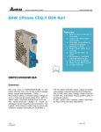
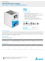
TECHNICAL DATASHEET CliQ DIN Rail Power Supply 24V 240W 1 Phase / DRP024V240W1AA Highlights & Features – – – – – – – – – Reliable design, with expected life of 10 years Compact, rugged design for ease of handling and installation Multiple connections to terminals allowed Designed for Class I Div. 2 Hazardous Locations environments Meets worldwide safety requirements RoHS Directive 2011/65/EU Compliant Worldwide AC input range without power de-rating Overvoltage / Overcurrent / Over Temperature Protections 150% Power Boost (steady state peak load) for 3 seconds Safety Standards CB Certified for worldwide use Model Number: DRP024V240W1AA Unit Weight: 1.04 kg Dimensions (L x W x D): 121 x 85 x 118.5 mm General Description The DRP024V240W1AA is part of the CliQ series of DIN Rail power supplies from one of the world’s largest power supply manufacturers and solution providers - Delta. This product provides an adjustable output capable of operating from input voltages at 85-264Vac, and a wide temperature range of -20°C to 75°C. With a rugged, compact plastic case design that meets shock and vibration requirements (in accordance to IEC60068-2-27 and IEC60068-2-6 respectively), and conformal-coated PCB assembly, this state of the art design is well suited to a broad variety of industrial applications worldwide. Model Information CliQ DIN Rail Power Supply Model Number Input Voltage Range Output Voltage Output Current DRP024V240W1AA 85-264Vac (120-375Vdc) 24Vdc 10A Model Numbering 1 DRP P 024V 240W 1 A A DIN Rail Power Supply Output Voltage Output Power Single Phase CliQ Series Metal Case All parameters are specified at 25°C ambient unless otherwise noted. www.DeltaPSU.com (December 2012, Rev. 02) TECHNICAL DATASHEET CliQ DIN Rail Power Supply 24V 240W 1 Phase / DRP024V240W1AA Specifications Input Ratings / Characteristics Nominal Input Voltage 100-240Vac Input Voltage Range 85-264Vac Nominal Input Frequency 50-60Hz Input Frequency Range 47-63Hz Nominal DC Input Voltage 125-250Vdc DC Input Voltage Range 120-375Vdc Input Current < 2.90A @ 115Vac, < 1.50A @ 230Vac Efficiency > 89.0% @ 115Vac, > 91.0% @ 230Vac Max Inrush Current Power Factor No Damage & l2t rating at all I/P device shall not exceed their rating > 0.96 @ 115Vac, > 0.90 @ 230Vac Leakage Current < 1mA @ 240Vac Output Ratings / Characteristics Nominal Output Voltage 24Vdc Output Voltage Tolerance ± 2% (initial set point tolerance) Output Voltage Adjustment Range 22-28Vdc Output Current 10A Output Power 240W Line Regulation < 0.5% typ. (@ 85-264Vac input, 100% input) Load Regulation < 1% typ. (@ 85-264Vac input, 0-100% input) Residual Ripple / PARD (20MHz) < 50mVpp / 240mVpp @ 25°C Rise Time < 100ms @ nominal input (100% load, 25°C) Start-up Time < 1000ms @ nominal input (100% load, 25°C) Hold-up Time > 20ms @ 115Vac & 230Vac (100% load, 25°C) Dynamic Response (Overshoot & Undershoot O/P Voltage) ± 5% @ 10-100% load Start-up with Capacitive Loads 10,000µF Max Mechanical Case Cover Aluminium Dimensions (L x W x D) 121 x 85 x 118.5 mm Unit Weight 1.04 kg Indicator Green LED (DC OK) Cooling System Terminal Wire Mounting Rail 2 Convection Input M4 x 3 Pins (Rated 300V/20A) Output M4 x 2 Pins (Rated 300V/20A) Input AWG 22-14 Output AWG 22-14 Standard TS35 DIN Rail in accordance with EN60715 All parameters are specified at 25°C ambient unless otherwise noted. www.DeltaPSU.com (December 2012, Rev. 02) TECHNICAL DATASHEET CliQ DIN Rail Power Supply 24V 240W 1 Phase / DRP024V240W1AA Environment Surrounding Air Temperature Operating -20°C to +75°C Storage -25°C to +85°C Power De-rating > 50°C de-rate power by 2.5% / °C > 70°C de-rate power by 4% / °C Operating Humidity < 95% RH (Non-Condensing) Operating Altitude 2,000 Meters Shock Test (Non-Operating) IEC60068-2-27, 30G (300m/S²) for a duration of 18ms Vibration (Non-Operating) IEC60068-2-6, 10Hz to 150Hz @ 50m/S² (5G peak); 90 min per axis for all X, Y, Z direction Bump IEC60068-2-29; 11ms / 10gn Pollution Degree 2 Protections Overvoltage 32V +10%, SELV Output, Hicc-up Mode, Non-Latching (Auto-Recovery) Overload / Overcurrent > 150% of rated load current, Hicc-up Mode, Non-Latching (Auto-Recovery) Over Temperature < 80°C Surrounding Air Temperature @ 100% load, Non-Latching (Auto-Recovery) Short Circuit Hicc-up Mode, Non-Latching (Auto-Recovery when the fault is removed) Degree of Protection IPX0 Protection Against Shock Class I without PE* connection *PE: Primary Earth Reliability Data 3 MTBF > 300,000 hrs. as per Telcordia SR-332 Expected Cap Life Time 10 years (115Vac & 230Vac, 50% load @ 40°C) All parameters are specified at 25°C ambient unless otherwise noted. www.DeltaPSU.com (December 2012, Rev. 02) TECHNICAL DATASHEET CliQ DIN Rail Power Supply 24V 240W 1 Phase / DRP024V240W1AA Safety Standards / Directives Electronic Equipment in Power Installations EN50718 / IEC62103 Electrical Safety SIQ to EN60950-1, UL/cUL recognized to UL60950-1, CSA C22.2 No. 60950-1, CB scheme to IEC60950-1, CSA to UL60950-1 and CSA C22.2 No. 60950-1 (File No. 181564) Industrial Control Equipment UL/cUL listed to UL508 and CSA C22.2 No. 107.1-01, CSA to CSA C22.2 No. 107.1-01 (File No. 181564) Hazardous Location / ATEX CSA to CSA C22.2 No. 213-M1987, ANSI / ISA 12.12.01:2007 (Class I, Division 2, Group A, B, C, D, T4) EN60079-0:2009, EN60079-15:2010 ( II 3G Ex nA IIc T4 Gc) Certificate No. ESP 09 ATEX 1 215 X; For IEC60079-0, IEC60079-15 II 3G ATEX 94/9/EC; IECEX Test Report CE In conformance with EMC Directive 2004/108/EC and Low Voltage Directive 2006/95/EC Material and Parts RoHS Directive 2011/65/EU Compliant Galvanic Isolation Input to Output 4.0KVac Input to Ground 1.5KVac Output to Ground 1.5KVac EMC EMC / Emissions CISPR22, EN55022, EN55011, FCC Title 47: Class B Immunity to 1) Electrostatic Discharge EN61000-4-2 Level 4 Criteria A Air Discharge: 15kV Contact Discharge: 8kV 1) Level 3 Criteria A 80MHz–1GHz, 10V/M with 1kHz tone / 80% modulation Radiated Field EN61000-4-3 Electrical Fast Transient / Burst EN61000-4-4 Level 3 Criteria A 2kV Surge IEC6100-4-5 Level 3 Criteria A 2) Common Mode : 2kV 3) Differential Mode : 1kV Conducted EN61000-4-6 Level 3 Criteria A 150kHz-80MHz, 10Vrms Power Frequency Magnetic Fields EN61000-4-8 Level 3 Criteria A 10A/Meter 1) 1) 1) 1) Voltage Dips EN61000-4-11 Level 3 Criteria A 100% dip; 1 cycle (20ms); Self Recoverable Low Energy Pulse Test (Ring Wave) IEC61000-4-12 Level 3 Criteria A 2) Common Mode : 2kV 3) Differential Mode : 1kV 1) Criteria A: Normal performance within the specification limits 2) Asymmetrical: Common mode (Line to earth) 3) Symmetrical: Differential mode (Line to line) 4 1) All parameters are specified at 25°C ambient unless otherwise noted. www.DeltaPSU.com (December 2012, Rev. 02) 1) TECHNICAL DATASHEET CliQ DIN Rail Power Supply 24V 240W 1 Phase / DRP024V240W1AA Block Diagram Device Description 1) 2) 3) 4) 5) 5 Input terminal block connector Output terminal block connector DC voltage adjustment potentiometer DC OK control LED (Green) Universal mounting rail system All parameters are specified at 25°C ambient unless otherwise noted. www.DeltaPSU.com (December 2012, Rev. 02) TECHNICAL DATASHEET CliQ DIN Rail Power Supply 24V 240W 1 Phase / DRP024V240W1AA Dimensions L x W x D: 121 x 85 x 118.5 mm Engineering Data De-rating Note 1. 2. 3. 4. Fig. 1.1 De-rating for Vertical Mounting Orientation > 50°C de-rate power by 2.5% / °C, > 70°C de-rate power by 4% / °C 6 All parameters are specified at 25°C ambient unless otherwise noted. www.DeltaPSU.com (December 2012, Rev. 02) 5. Power supply components may degrade, or be damaged, when the power supply is continuously used outside the shaded region, refer to the graph shown in Fig. 1.1. If the output capacity is not reduced when the surrounding air temperature >50°C, the device will run into Over Temperature Protection. When activated, the output voltage will go into bouncing mode and will recover when the surrounding air temperature is lowered or the load is reduced as far as necessary to keep the device in working condition. If the device has to be mounted in any other orientation, please do not hesitate to contact [email protected] for more details. In order for the device to function in the manner intended, it is also necessary to keep a safety distance of 20mm with adjacent units while the device is in operation. Depending on the surrounding air temperature and output load delivered by the power supply, the device housing can be very hot! TECHNICAL DATASHEET CliQ DIN Rail Power Supply 24V 240W 1 Phase / DRP024V240W1AA Output De-rating VS. Input Voltage ■No output power de-rating across the entire input voltage range Assembly & Installation The power supply unit (PSU) can be mounted on 35mm DIN rails in accordance with EN60715. The device should be installed with input terminal blocks at the bottom. Each device is delivered ready to install. Mounting Dismounting Fig. 2.1 Mounting Fig. 2.2 Dismounting Snap on the DIN rail as shown in Fig. 2.1: 1. Tilt the unit upwards and insert it onto the DIN rail. 2. Push downwards until stopped. 3. Press against the bottom front side for locking. 4. Shake the unit slightly to ensure that it is secured. To uninstall, pull or slide down the latch with screw driver as shown in Fig 2.2. Then slide the power supply unit (PSU) in the opposite direction, release the latch and pull out the power supply unit (PSU) from the rail. 7 All parameters are specified at 25°C ambient unless otherwise noted. www.DeltaPSU.com (December 2012, Rev. 02) TECHNICAL DATASHEET CliQ DIN Rail Power Supply 24V 240W 1 Phase / DRP024V240W1AA Safety Instructions – – – – – – – – ALWAYS switch mains of input power OFF before connecting and disconnecting the input voltage to the unit. If mains are not turned OFF, there is risk of explosion / severe damage. To guarantee sufficient convection cooling, keep a distance of 50mm above and below the device as well as a lateral distance of 20mm to other units. Note that the enclosure of the device can become very hot depending on the surrounding air temperature and load of the power supply. Risk of burns! Only plug in and unplug connectors when power is turned off! DO NOT insert any objects into the unit. Hazardous voltages may be present for up to 5 minutes after the input mains voltage is disconnected. Do not touch the unit during this time. The power supplies unit must be installed in an IP54 enclosure or cabinet in the final installation. The enclosure or cabinet must comply with EN60079-0 or EN60079-15. The power supplies are built in units and must be installed in a cabinet or room (condensation free environment and indoor location) that is relatively free of conductive contaminants. Functions ■ Graph illustrating the Start-up Time, Rise Time, and Hold-up Time Start-up Time The time required for the output voltage to reach 90% of its set value, after the input voltage is applied. Rise Time The time required for the output voltage to change from 10% to 90% of its set value. Hold-up Time Hold up time is the time when the AC input collapses and output voltage retains regulation for a certain period of time. The time required for the output to reach 95% of its set value, after the input voltage is removed. 8 All parameters are specified at 25°C ambient unless otherwise noted. www.DeltaPSU.com (December 2012, Rev. 02) TECHNICAL DATASHEET CliQ DIN Rail Power Supply 24V 240W 1 Phase / DRP024V240W1AA Inrush Current Surge Load Inrush current is the peak, instantaneous, input current measured and, occurs when the input voltage is first applied. For AC input voltages, the maximum peak value of inrush current will occur during the first half cycle of the applied AC voltage. This peak value decreases exponentially during subsequent cycles of AC voltage. It is the reserve power available constantly that allows reliable startup of loads with high inrush current. After the output has reached its steady state set value, the power supply can support surge loads of up to 150% of maximum rated load (Io Max), for a maximum duration of 3 seconds. The maximum allowed rate of load change is 0.1amps per microseconds, and the voltage can vary ±5% from the set value during the duration of the surge load. Step Load Response The power supply output voltage will remains within ±5% of its steady state value, when subjected to a dynamic load from 10 to 100% of its rated current. Overload & Overcurrent Protections The power supply’s Overload (OLP) and Over current (OCP) Protections will be activated when output current exceeds 150% of IO (Max load). In such occurrence, the VO will start to droop and once the power supply has reached its maximum power limit, the protection is activated and the power supply will go into “Hiccup mode” (Auto-Recovery). The power supply will recover once the fault condition of the OLP and OCP is removed and IO is back within the specifications. Overvoltage Protection The power supply’s overvoltage circuit will be activated when its internal feedback circuit fails. The output voltage shall not exceed its specifications defined on Page 3 under “Protections”. 9 Additionally, if the IO is <150% but >100% for a prolong period of time (depending on the load), the Over Temperature Protection (OTP) will be activated due to high temperature on critical components. The power supply will then go into “Hiccup mode” until the fault is removed. All parameters are specified at 25°C ambient unless otherwise noted. www.DeltaPSU.com (December 2012, Rev. 02) TECHNICAL DATASHEET CliQ DIN Rail Power Supply 24V 240W 1 Phase / DRP024V240W1AA Over Temperature Protection Short Circuit Protection As mentioned above, the power supply also has Over Temperature Protection (OTP). This is activated when the overload condition persists for an extended duration and the output current is below the overload trigger point but >100% load. In the event of a higher operating condition at 100% load, the power supply will run into OTP when the surrounding air temperature is >80°C. When activated, the output voltage will go into bouncing mode until the operating surrounding air temperature drops to 50°C or output capacity is reduced as recommended in the derating graph. The power supply’s output OLP/OCP function also provides protection against short circuits. When a short circuit is applied, the output current will operate in “Hiccup mode”, as shown in the illustration in the OLP/OCP section on this page. The power supply will return to normal operation after the short circuit is removed. Operating Mode Redundancy Operation In order to ensure proper redundancy operation for the power supply unit (PSU), ensure that the output voltage difference between the two units is kept at 0.45~0.50V for 24V supplies. Follow simple steps given below to verify: Step 1. Measure output voltage of PSU 1 and PSU 2. If PSU 1 is the master unit, then Vo of PSU 1 must be higher than PSU 2. In order to set the output voltage, connect the power supply to 50% load and set the PSU 1 and PSU 2 output voltage. Step 2. Connect the right DRR module, 20A as per the system requirement to the power supply units PSU 1 and PSU 2 at Vin 1 & Vin 2 respectively. Fig. 3.1 Redundancy / Parallel Operation Connection Diagram *Vdrop will vary from 0.60V to 0.90V (Typical 0.65V) depending on the load current and surrounding air temperature. Step 3. Connect the system load from Vout. Please note that output voltage Vout from DRR module will be = VO (output voltage of power supply) – Vdrop* (in DRR module). Parallel Operation These DRR modules can also be used for Parallel function in order to increase the output power by N+1 (e.g. 2.5A + 2.5A = 5A or 2.5A + 2.5A + 2.5A = 7.5A) or current sharing, and thus increasing the power supply and system reliability. Though the DRP024V240W1AA is not designed for current sharing, a good current sharing between two power supplies can be achieved by following simple steps as below (Refer to Fig. 3.1 for the Connection Diagram). Step 1. Set output load condition for both supplies at 50% and measure the output voltages. Step 3. Connect PSU 1 and PSU 2 with the DRR-20A module and measure at Vin 1 & Vin 2 to verify the voltage difference. Ensure the voltages are within ±25mV. Step 2. Adjust output voltages to the same level or within ±25mV difference. Step 4. Output voltage from DRR module Vout will be = VO (output voltage of power supply) – Vdrop* (in DRR module). *Vdrop will vary from 0.60V to 0.90V (Typical 0.65V) depending on the load current and surrounding air temperature. 10 All parameters are specified at 25°C ambient unless otherwise noted. www.DeltaPSU.com (December 2012, Rev. 02) TECHNICAL DATASHEET CliQ DIN Rail Power Supply 24V 240W 1 Phase / DRP024V240W1AA Others Delta RoHS Compliant Restriction of the usage of hazardous substances The European directive 2011/65/EC limits the maximum impurity level of homogeneous materials such as lead, mercury, cadmium, chrome, polybrominated flame retardants PBB and PBDE for the use in electrical and electronic equipment. RoHS is the abbreviation for “Restriction of the use of certain hazardous substances in electrical and electronic equipment”. This product conforms to this standard. Conformal Coating The Protective Coating Technology Delta Electronics Group has designed the perfect dipping technique which penetrates everywhere including under device, and prevents leakage. The conformal coating dipping can be applied to PCBs or circuit board. The coating preserves the performance of precision electronic primarily by preventing ionizable contaminants such as salt from reaching circuit nodes, where the material slumps around sharp edges. This can be a problem especially in highly conversing atmosphere. 11 All parameters are specified at 25°C ambient unless otherwise noted. www.DeltaPSU.com (December 2012, Rev. 02)