1
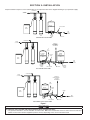
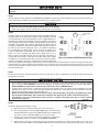
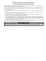
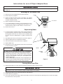
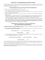
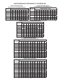
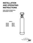
INSTALLATION AND OPERATING
INSTRUCTIONS
CHEM-FREE IRON REDUCTION SYSTEMS
MODELS:
MCA0750
MCA1000
MCA1500
MCA2000
MCA0751
MCA1001
MCA1501
MCA2001
MCA3001
APIR075S
APIR100S
APIR200S
APIR075M
APIR100M
APIR200M
MCA0750M
MCA1000M
MCA1500M
MCA2000M
MCA0751M
MCA1001M
MCA1501M
MCA2001M
MCA3001M
Installer, please leave with homeowner.
a 3M company
CUNO Incorporated
400 Research Parkway
Meriden, CT 06450 U.S.A.
www.cuno.com
Manufactured and sold under U.S. Patent Number 3,649,532
IN105 0607
SAFETY INFORMATION
Read, understand, and follow all safety information contained in these instructions prior to installation and use of the CUNO
MCA/APIR Series Chem-Free Iron Reduction Systems. Retain these instructions for future reference.
Intended use:
The CUNO Chem-Free Iron Reduction Systems are intended for use in reducing dissolved and precipitated iron in water in homes
and have not been evaluated for other uses. The system is intended for indoor installations near the entry point of a home water line,
and must be installed by qualified professional installers according to these installation instructions.
EXPLANATION OF SIGNAL WORD CONSEQUENCES
WARNING
Indicates a potentially hazardous situation, which, if not avoided, could result in death or serious
injury and/or property damage.
CAUTION
Indicates a potentially hazardous situation which, if not avoided, may result in minor or moderate
injury and/or property damage.
CAUTION
Indicates a potentially hazardous situation, which, if not avoided, may result in property damage.
WARNING
To reduce the risk associated with ingestion of contaminants:
• Do not use with water that is microbiologically unsafe or of unknown quality without adequate disinfection before or after the
system.
To reduce the risk associated with hazardous voltage:
• If the home electrical system requires use of the cold water system as an electrical safety ground, a jumper must be used to
ensure a sufficient ground connection across the filter installation piping — refer installation to qualified personnel.
• Do not use the Iron Reduction Filter if the wall-mounted power supply is damaged — contact qualified service personnel
for repair.
To reduce the risk associated with back strain:
• Follow safe lifting procedures.
CAUTION
To reduce the risk associated with skin, eye, and respiratory tract irritation from dust from filter media during installation:
• Gravel and several types of filter media may be used in this product, depending upon the application. During installation, dust
may cause irritation to skin, eyes, and respiratory tract, and may affect lungs.
• Utilize a NIOSH-approved dust filter mask and appropriate eye protection when handling and pouring gravel and filter media.
• Refer to MSDS documents for further safety information.
CAUTION
To reduce the risk associated with property damage due to water leakage:
•
•
•
•
•
•
•
•
•
•
•
•
Read and follow Use Instructions before installation and use of this system;
Installation must comply with existing state or local plumbing codes;
Protect from freezing. Drain system when temperatures drop below 40°F (4.4°C);
Do not install if water pressure exceeds 100 psi (689 kPa). If the system water pressure exceeds 100 psi, the installation
must use a pressure limiting valve. Contact a licensed plumbing professional if you are uncertain how to check your water
pressure;
Do not install system where water lines could be subjected to vacuum conditions without appropriate measures for vacuum
prevention;
The system must be installed on cold water lines only, maximum temperature 100°F (38°C);
When water supply is shut off, shut off fuel or electric power to water heater;
Do not use torches or other heat sources near plastic plumbing, as damage may occur;
Take care when using pliers or pipe wrenches to tighten plastic fittings, as damage may occur;
On plastic fittings, use thread sealing tape only. Never use pipe sealant or pipe dope on plastic fittings, as damage may occur;
Do not bend spring on float assembly or damage to the vent may result;
Do not install this system in direct sunlight or outdoors without protection from precipitation.
To reduce the risk associated with property damage due to plugged water lines:
• Pay particular attention to correct orientation of control valve. Water flow should match arrow on control valve. The Inlet and
Outlet of other water treatment equipment products will vary depending on the control valve brand used.
IMPORTANT NOTES
• Failure to follow instructions may result in leakage and will void warranty.
TABLE OF CONTENTS
SECTION
DESCRIPTION
1
GENERAL INFORMATION
2
BEFORE INSTALLATION
3
INSTALLATION
4
BACKWASHING INSTRUCTIONS
5
PLUMBING SYSTEM CLEAN-UP
6
MAINTENANCE
7
TROUBLESHOOTING
8
SPECIFICATIONS AND OPERATING DATA
9
WARRANTY
SECTION 1: GENERAL INFORMATION
Congratulations on your purchase of a Chem-Free Iron Reduction System! The Chem-Free System reduces dissolved, precipitated
and bacterial iron from your water supply. Contrary to conventional methods, your Chem-Free System requires NO chemicals (either
added to the water supply or the filter). This unique process requires ONLY periodic backwashing for a few minutes to flush out entrapped iron that has accumulated in the filter tank.
When properly installed, the Chem-Free Iron Reduction System will provide many years of virtually trouble-free service. Read this
manual all the way through first, and then follow the instruction steps in the proper sequence.
Description and Operation of the System:
The Chem-Free Reduction Filter consists of two major components which are:
1)
A HYDRO-CHARGER located between the well head and the pressure tank, which adds a small amount of air to the iron-laden
water whenever the well pump runs.
2)
A backwashing type filter containing a special media that causes the iron in the “Hydro-Charged” water to precipitate throughout the
filter bed (rather than on the surface as in chemical oxidizing filters). This process produces an iron reduction capacity of 30,000 to
50,000 parts per million (ppm) compared to 6,000 to 8,000 ppm for chemical oxidation processes. The media DOES NOT require
a chemical regenerant (such as potassium permangante) for oxygen enrichment, salt, chlorine or any other chemicals.
Your Chem-Free Reduction Filter automatically adjusts the pH to neutral or higher on acid water WITHOUT an acid neutralizer (a
required piece of equipment with chemical oxidation filters whenever the pH is less than 6.7). The ability to raise pH when it is below
neutral (7 or less) greatly enhances the Chem-Free System’s ability to reduce iron efficiently.
IMPORTANT NOTES
Replenishment of the component of the filter media that adjusts pH, “MpH Adder”, may be required periodically, the frequency of
which is dependent on the raw water pH, the manganese (Mn) concentration in the water (if any) and the water consumption rate.
Periodic backwashing of the filter bed flushes the precipitated iron to the drain and readies the filter for use again. The duration of
the backwash procedure will vary depending on several factors, but generally totals just 10 minutes (factory setting). The frequency
of backwashing depends on iron concentration and water usage, and ranges from daily to once every 12 days. The volume of water
consumed during the entire backwashing procedure is approximately 50 gallons (1 cu. ft. models).
1-1
SECTION 2: BEFORE INSTALLATION
Inspecting And Handling Your Iron Reduction Filter:
Inspect the equipment for shipping damage. If damaged, notify the transportation company and request a damage inspection.
Handle the filter unit with care. Damage can result if dropped or if set on sharp, uneven projections on the floor. Do not turn the filter unit
upside down.
CAUTION
To reduce the risk associated with property damage due to water leakage:
• Installation must comply with existing state or local plumbing codes;
Make Sure Your Water Has Been Thoroughly Tested:
An analysis of your water should be made prior to the selection of your water conditioning equipment. Your dealer will generally perform
this service for you, and may send a sample to the factory for analysis and recommendations. Enter your analysis below for a permanent
record.
IMPORTANT NOTES
• Hydrogen Sulfide (H2S) MUST be tested for at the well site with the well pump running. An on-site test is more accurate for
other contaminants as well and should be performed. For accuracy, the sample must be drawn with the pump RUNNING, and
the test be completed within ONE minute after the sample is drawn.
Analysis Of Your Water
CONTAMINANT
YOUR WATER
Iron (Fe)
___________ppm
Manganese (Mn)
___________ppm
pH
___________ppm
Tannins (Humic Acid)
___________ppm
Hydrogen Sulfide (H2S)
___________ppm
Hardness
___________gpg
Other____________________
___________ppm
Other____________________
___________ppm
The following description of the water constituents listed above on the selection of the appropriate Chem-Free model, and their effect on
its operation will help to highlight their significance:
Iron (Fe)
Iron concentrations as low as 0.3 ppm (0.1 ppm under some conditions) will cause staining. The iron concentration, together with the flow
rate demand and the consumption rate of the water determines the basic size filter system. The higher these factors are, the larger the required system. The Chem-Free Iron Reduction System is capable of reducing the three main types of iron found in water supplies: Soluble
Iron (also known as clear water iron); Precipitated Iron (also known as red iron); and Bacterial Iron. There is an upper limit of 15 ppm iron
concentration for the Chem-Free System; special care must be taken when selecting a filter model if your water has a combination of high
iron, very low pH and/or manganese levels above 0.2 ppm.
The Chem-Free System is not bactericidal, i.e. it does not remove or kill “bacterial iron”. It reduces the iron upon which the bacteria may
live or which it deposits in your plumbing fixtures, thus helping to eliminate its effects.
Manganese (Mn)
The presence of manganese can be bothersome, even for a Chem-Free Iron Reduction filter (and it is devastating for chemical oxidizing
systems). As little as 0.05 ppm of manganese can produce a brownish or black stain. The ability of the filter to reduce manganese depends
on its concentration and the pH of the water.
Although not specifically designed for the reduction of manganese, the oxidation of manganese is very similar to that of iron. It’s oxidation
is more pH dependent than that of iron, therefore a pH of 8.2 or higher must be obtained. When this pH level is achieved, the precipitation
of manganese may more readily occur. To accomplish this, models are available where the media contains additional quantities of MpH
Adder, the pH raising component (model designations with “M” suffix). In any application involving manganese, a larger model filter is
2-1
generally recommended (but only if the pumping rate is sufficient to backwash the larger size).
If, however, the manganese concentration is low (0.1 ppm or less) and the pH is 6.5 or higher, a Chem-Free Iron Reduction filter containing
standard Chem-Free filter media will generally perform satisfactorily, although backwashing should be performed at more frequent intervals. Under more severe conditions where the pH is very low and/or the manganese concentration is high, an acid neutralizer or chemical
feed pump injecting soda ash installed ahead of the filter will maintain the required 8.2 pH level longer than the Chem-Free Iron Reduction
filter will between replenishments with MpH Adder.
pH
The pH of water measures its acidity. Water with a pH of less than 7.0 is acidic, above 7.0 is alkaline, and a pH of 7.0 is neutral. The lower
the pH value the greater the acidity, and the higher the pH value the more alkaline. Acidic water (pH less than 7.0) is corrosive to pipes,
appliances, etc. A pH of 7.0 or higher facilitates iron reduction – which is why the Chem-Free Iron Reduction filter is designed to increase
the pH when it is less than 7.0.
The pH increasing component of the media is “sacrificial,” that is, it slowly dissolves during the process of increasing pH. The rate this
occurs is proportional to the degree of the pH increase and the water consumption rate (i.e., the greater the pH increase and water consumption, the greater the sacrificial rate). Thus, when the pH is increased to 8.2 or more, as is necessary when manganese is present,
the sacrificial rate is even greater. Under the most severe conditions, the MpH Adder component of the media may have to be replenished
two to four times per year. On the other hand, if the raw water pH is 7.0 or above and no manganese is present, the sacrificial rate is very
slight (See NOTE, Sec. 1).
Tannins (Humic Acid)
Tannins (a humic acid), which may be present in some water supplies, are the result of various forms of decaying vegetation (the test for
tannins can be performed by your dealer). Tannins can cause problems in the operation of the Chem-Free Iron Reduction filter by forming
a sticky coating on the media, thus rendering it incapable of filtering the iron. Generally, with tannin concentrations of 0.5 ppm or less,
more frequent backwashing will prevent the sticky coating from forming. It does appear, however, that the level of tannin concentration
affects the operation of the Chem-Free Iron Reduction filter differently in different geographical areas (in some areas, the Chem-Free Iron
Reduction filter will perform satisfactorily when tannin concentration is considerably greater than 0.5 ppm). It is therefore recommended
that if the tannin concentration is 0.5 ppm or more, contact your dealer BEFORE installing the system.
Hydrogen Sulfide (H2S)
Hydrogen sulfide (often referred to as “sulfur”) is easily detectable by its objectionable “rotten egg” odor. Sulfur corrodes iron, brass, copper
and silver. While the Chem-Free Iron Reduction filter is not intended to be used as a sulfur filter, it is capable of reducing sulfur in concentrations of up to 2 or 3 ppm, and sometimes as high as 5 ppm. Whenever hydrogen sulfide is present, backwashing must be performed at
more frequent intervals, and the pumping system MUST include a standard air-to-water pressure tank with an air-relief valve.
2-2
Check Your Water Pressure And Pumping Rate:
Two water system conditions must be checked carefully to avoid unsatisfactory operation or equipment damage:
1)
MINIMUM water pressure required at the filter tank inlet is 20 psi and MAXIMUM water pressure is 100 psi. If you have a private
well, the gauge on the pressure tank will indicate the high and low system pressure. Record your water pressure data below:
WATER PRESSURE:
Low___psi
High___psi
CAUTION
To reduce the risk associated with property damage due to water leakage:
• Do not install if water pressure exceeds 100 psi (689 kPa). If the system water pressure exceeds 100 psi, the installation
must use a pressure limiting valve. Contact a licensed plumbing professional if you are uncertain how to check your water
pressure.
2)
The pumping rate of your well pump must be sufficient for satisfactory operation of the Hydro-Charger and to BACKWASH the
filter. Refer to SPECIFICATIONS AND OPERATING DATA for the backwash requirement for each model. To measure the pumping rate of your pump, follow these instructions:
a.
Make certain no water is being drawn. Open spigot nearest pressure tank. When pump starts, close spigot and measure
time (in seconds) to refill pressure tank (when pump shuts off). This figure represents CYCLE TIME.
b.
With the pressure tank full, draw water into a container of known volume, measure the number of gallons drawn until the
pump starts again. This is DRAW-DOWN. Divide this figure by CYCLE TIME and multiply the result by 60 to arrive at the
PUMPING RATE in gallons per minute (gpm). To aid in your calculation, insert the data in the following formula:
DRAW-DOWN ______ (gals.) ÷ CYCLE TIME ______ (secs.) x 60 = PUMPING RATE ______(gpm)
EXAMPLE:
CYCLE TIME is 65 secs.; DRAW-DOWN is 6 gals.; then PUMPING RATE equals: 6 gals. ÷ 65 secs. x 60 = 5.5 gpm
IMPORTANT NOTE
The addition of the Hydro-Charger to the pumping system or plumbing and other water treatment devices (such as an acid neutralizer) may reduce the flow rate at the filter drain to an inadequate level to properly backwash the filter. If you are uncertain whether
your flow rate is adequate, contact your dealer BEFORE installing your Chem-Free Iron Reduction filter, so that corrective action,
if required, may be taken.
Locate Iron Reduction System Correctly:
Select the location of your filter tank with care. Various conditions which contribute to proper location are as follows:
1)
Locate as close as possible to water supply source.
2)
Locate as close as possible to a floor or laundry tub drain.
3)
Locate in correct relationship to other water conditioning equipment (See Figure 1, in Section 3).
4)
Filters and softeners should be located in the supply line BEFORE the water heater. Temperatures above 100° F (38° C) damage
filters and softeners and will also void the factory warranty.
5)
Do NOT install a filter or softener in a location where freezing temperatures occur. Freezing may cause permanent damage to
this type of equipment and will void the factory warranty.
6)
Allow sufficient space around the unit for easy servicing.
7)
If your water sources is a community water supply, a public water supply, OR you wish to bypass water used for a geothermal
heat pump, lawn sprinkling, outbuildings or other high demand applications, refer to Figure 1 for additional equipment required.
Also, refer to the Special Instructions following installation procedures.
The Importance Of Your Pressure Tank:
The pressure tank found on private well systems becomes an integral part of the Chem-Free Iron Reduction System by providing
necessary mixing and “residence time” to the “Hydro-Charged” water. While the Chem-Free Iron Reduction Filter System will perform
satisfactorily with either a captive-air (bladder) type pressure tank or a standard air-to-water type with an air volume control (air-relief
valve), the bladder type requires more careful adjustment of the Hydro-Charger to prevent gases from collecting in the pressure tank
and the head area of the filter tank.
2-3
IMPORTANT NOTES
A properly sized pressure tank of either style will require a minimum pump cycle of 60 seconds to refill from the well pump on-to-off
pressure settings. If cycle time of pump is less than 60 seconds, pressure tank is too small, causing excessive wear on the pump
and probable failure of the filter system.
Under more severe operating conditions (low pH, high iron, manganese and small concentrations of sulfur), a standard air-to-water
type pressure tank with an air-relief valve MUST be used (if bladder type tank is already in place, do not remove it. Install the air-towater pressure tank between the Hydro-Charger and the bladder type-tank).
IMPORTANT NOTE
If your pressure tank (or any part of your water system) is not functioning properly, corrective action MUST be taken BEFORE
installation of your Chem-Free Iron Reduction Filter.
Facts To Remember While Planning Your Installation:
WARNING
To reduce the risk associated with hazardous voltage:
• If the home electrical system requires use of the cold water system as an electrical safety ground, a jumper must be used to
ensure a sufficient ground connection across the filter installation piping — refer installation to qualified personnel.
CAUTION
To reduce the risk associated with property damage due to water leakage:
• Installation must comply with existing state or local plumbing codes.
• Do not install if water pressure exceeds 100 psi (689 kPa). If the system water pressure exceeds 100 psi, the installation
must use a pressure limiting valve. Contact a licensed plumbing professional if you are uncertain how to check your water
pressure.
• Do not install system where water lines could be subjected to vacuum conditions without appropriate measures for vacuum
prevention.
• Do not use torches or other heat sources near plastic plumbing, as damage may occur.
• Take care when using pliers or pipe wrenches to tighten plastic fittings, as damage may occur.
• On plastic fittings, use thread sealing tape only. Never use pipe sealant or pipe dope on plastic fittings, as damage may occur.
To reduce the risk associated with property damage due to plugged water lines:
• Pay particular attention to correct orientation of control valve. Water flow should match arrow on control valve. The Inlet and
Outlet of other water treatment equipment products will vary depending on the control valve brand used.
All water to be treated MUST pass through the Hydro-Charger Assembly, pressure tank and the Chem-Free Filter. Refer to the special
instructions for a split-stream installation. System may malfunction if this instruction is ignored.
If lawn sprinkling, a swimming pool, geothermal heating/cooling or water for other devices/activities are to be treated by the ChemFree Iron Reduction filter, a larger model filter MUST be selected to accommodate the higher demands of these items. The pumping
rate of the well pump must be sufficient to accommodate these items plus the backwashing requirement of the filter. Consult your
dealer for alternative instructions if the pumping rate is insufficient.
Remember that the filter INLET is attached to the pipe that supplies water (i.e. runs to the pump) and OUTLET is the line that runs
toward the water heater or other water treatment equipment device.
Before commencing the installation, it is advisable to study the existing piping system and to determine the size, number and type of
fittings required. Typical system schematics shown in Figure 1 will be of assistance.
2-4
SECTION 3: INSTALLATION
Proper installation sequence of iron reduction filter is very important. Refer to the diagram following for your particular supply.
FILTERED WATER
FILTERED
SOFT WATER
PRESSURE
HYDRO-CHARGER
TANK
BRINE
MAKER
RAW
WELL
WATER
SOFTENER
IRON
REDUCTION
FILTER
PRESSURE
SWITCH.
CHECK VALVE
STANDARD WELL INSTALLATION
FILTERED WATER
FILTERED
SOFT WATER
WATER FOR
LAWN SPRINKLERS
OR OTHER
HIGH DEMAND
TO
110 V
OUTPUT
SECONDARY
PRIMARY
SOLENOID
VALVE
PRESSURE
PRESSURE
TANK
TANK
BRINE
MAKER
SOFTENER
RAW
WELL
WATER
IRON
REDUCTION
FILTER
SECONDARY
PRESSURE
SWITCH.
HYDRO-CHARGER
CHECK VALVE
PRIMARY
PRESSURE
SWITCH.
SPLIT-STREAM INSTALLATION
FILTERED WATER
FILTERED
SOFT WATER
WATER FOR
LAWN SPRINKLERS
OR OTHER
HIGH DEMAND
TO
110 V
OUTPUT
SOLENOID
VALVE
PRESSURE
TANK
METER
BRINE
MAKER
SOFTENER
IRON
REDUCTION
FILTER
RAW
WATER
PRESSURE
SWITCH.
HYDRO-CHARGER
CHECK VALVE
PUBLIC WATER SUPPLY INSTALLATION
Figure 1
CAUTION
To reduce the risk associated with property damage due to plugged water lines:
• Pay particular attention to correct orientation of control valve. Water flow should match arrow on control valve. The Inlet and
Outlet of other water treatment equipment products will vary depending on the control valve brand used.
3-1
IMPORTANT NOTE
Read Section 4, PLUMBING SYSTEM CLEANUP, for instructions on some procedures that MAY need to be performed prior to
installation.
Step 1
Shut off all water at main supply. On a PRIVATE WELL SYSTEM, turn off power to pump and drain pressure tank. Make certain pressure is relieved from complete system by opening nearest faucet to drain system.
CAUTION
To reduce the risk associated with property damage due to water leakage:
• When water supply is shut off, shut off fuel or electric power to water heater.
Step 2
Cut main supply line as required to fit Hydro-Charger in plumbing between
well pump and pressure tank (Hydro-Charger may be installed in a vertical
or horizontal position). The Hydro-Charger has been supplied with both 1”
threaded and 1” barbed (insert) fittings to allow for installation with various
types of piping materials. When using the threaded nipples, use thread tape
only. When using barbed (insert) fittings, appropriate pipe clamps must be
used. Once installed, the quick release nipples allow the Hydro-Charger to
be rotated, so the air draw adjustment screw is accessible for adjustment
by a small bladed screwdriver. Allow at least 10 inches of straight run of
1” pipe on both INLET and OUTLET side of the Hydro-Charger. Refer to
Figure 2 for correct assembly. The quick release nipples also acts as a
union to facilitate the Hydro-Charger removal, inspection and cleaning as
needed. With an installation on PVC pipe and copper tubing it may require
Figure 2: HYDRO-CHARGER INSTALLATION
the addition of a normal plumbing union to aid in removal from the plumbing due to the rigidity of that type of material. Make certain the directional
arrows on the Hydro-Charger points toward the pressure tank and the pressure control switch is located on the pressure tank side of
Hydro-Charger as in Figure 1. Rapid cycling of pump may occur if the pressure control switch is located on well side. If a check valve
is located between Hydro-Charger and pressure tank, it may prevent the Hydro-Charger from performing properly. Relocate to well
side of Hydro-Charger.
Step 3
Turn back on the power to the well pump and pressurize the water lines to allow for adjustment of the Hydro-Charger. Check for leaks
and adjust as necessary.
IMPORTANT NOTES
• Do not apply heat near Hydro-Charger, as damage may occur. On badly scaled, older plumbing systems, it may be advantageous to install a WYE STRAINER to help prevent plugging of the Hydro-Charger nozzle with scale or debris. The use of a
WYE STRAINER must precede the Hydro-charger on the inlet side by a MINIMUM OF 10”.
• If existing water system includes a captive-air type pressure tank (bladder) and it is desirable to install an additional air to water
type with an air release (not as a split steam type installation) install an air to water type pressure tank between the HydroCharger and the existing captive air type pressure tank.
• Before proceeding with Hydro-Charger installed, re-verify adequate pumping rate pumping by following the procedure described in SECTION 2. After verification of adequate flow, depressurize system as described previously.
• If installation is to be split streamed prior to filter vessel or is a public water supply see Figure 1, or refer to Special
Instructions on page 3-6.
Step 4
Set Hydro-Charger by following these steps:
a)
Open nearest faucet until well pump starts, then close faucet.
b)
Place a finger lightly over the SUCTION PORT (Figure 3). A slight suction
should be detected for approximately ONE THIRD (1/3) of pumping cycle
time. (Do not confuse with ONE THIRD (1/3) of pressure range).
c)
If suction is too short, increase by turning air adjustment screw (Figure 3),
CLOCKWISE. To decrease duration, turn COUNTERCLOCKWISE.
d)
Repeat steps (a) through (c) until proper setting is obtained. The optimum cycle time is 60 seconds or more, with an air
draw of 20 seconds minimum. Position DRAIN LINE over drain and secure firmly. To prevent back-siphoning of sewer water,
3-2
Figure 3
provide an air gap of at least 2 inches or 2 pipe diameters between
end of drain hose and drain (Figure 6). Do not raise DRAIN LINE
more than 10 ft. above floor.
IMPORTANT NOTE
When the duration of the suction is too long, the cold water may have a
milky appearance caused by excess air in the water system. Correct this
condition by reducing the duration of suction. This condition is commonly
associated with bladder type pressure tanks. In extreme cases where
elimination of excess air prevents system from performing satisfactorily,
it may be necessary to install an air to water pressure tank with an air
release valve.
FUNNEL
Step 5
FILLPORT
BODY
If media is already in the MEDIA TANK proceed to Step 6. If media is shipped
separately, add media through fillport adapter using funnel (Figure 4). Fillport
cap can be removed by removing the quick release clip. NEVER ADD MEDIA
ABOVE LINE INDICATED ON SIDE OF TANK. You may have received more
media than required for the initial fill, save extra media for future replenishment.
Figure 4. FILLING MEDIA TANK
Reinstall fillport cap. Make sure cap is fully inserted before reinstalling clip.
OUT IN
CAUTION
YOKE
CLIP & SCREW
BYPASS
FLAT CAP
BYPASS
To reduce the risk associated with skin, eye, and respiratory tract irritation from dust from filter media during installation:
• Gravel and several types of filter media may be used in this product,
depending upon the application. During installation, dust may cause
irritation to skin, eyes, and respiratory tract, and may affect lungs.
• Utilize a NIOSH-approved dust filter mask and appropriate eye protection when handling and pouring gravel and filter media.
• Refer to MSDS documents for further safety information.
BYPASS VALVE
DRAIN LINE
ELBOW
CONTROL VALVE BODY
FLOW CONTROL ASSEMBLY
FILL PORT
ADAPTER
SET SCREW
Step 6
Turn off the electrical source to the water well pump or the close the water
shut off valve on a municipal water supply to the dwelling once again. Depressurize the water system by opening the nearest faucet to drain water
from the water system in order to allow the installation of the Chem-Free
Iron Reduction System.
Step 7
ROTATE
KNOBS
SERVICE
BYPASS
Figure 5 . INLET/OUTLET CONNECTIONS
Determine location and cut the water line on the supply side of the pressure
tank as required to fit the plumbing to the control valve connection fittings.
You may want to install a separate three valve bypass prior to the control valve in case the supplied bypass valve requires maintenance in order to provide undisturbed water use.
Step 8
Assemble and attach bypass valve to the control valve. See Figure 5 if needed. Make certain the water enters inlet and discharges
through the outlet side of the bypass valve. Arrows can be viewed on the bypass valve to confirm the correct flow path. At this time
make certain the bypass valve is in the bypass position and leave in that position until instructed to place in the service position. Refer
to Figure 5 for proper operation.
CAUTION
To reduce the risk associated with property damage due to water leakage:
• Do not use torches or other heat sources near plastic plumbing, as damage may occur.
• Take care when using pliers or pipe wrenches to tighten plastic fittings, as damage may occur.
• On plastic fittings, use thread sealing tape only. Never use pipe sealant or pipe dope on plastic fittings, as damage may occur.
3-3
Step 9
Loosen SET-SCREW and pull out DRAIN LINE FLOW CONTROL (DLFC)
assembly from VALVE BODY (see Figure 5). Unscrew DRAIN LINE ELBOW
from DLFC. Apply PTFE tape to threads. Reassemble to VALVE BODY, making certain DLFC assembly is FULLY inserted into VALVE BODY before tightening SET-SCREW.
Attach DRAIN LINE to DRAIN LINE FITTING. To prevent back pressure
from reducing flow rate below minimum required for backwash, DRAIN LINE
MUST be sized according to run length and relative height. Be careful not to
bend flexible drain tubing sharply enough to cause “kinking” (if kinking occurs
DRAIN LINE MUST be replaced!).
EQUIPMENT
DRAIN LINE
AIR GAP
2" REF.
DRAIN
Typical examples of proper DRAIN LINE diameters are:
1 )1/2 in. ID up to 15 ft. when discharge is lower than inlet.
2) 5/8 in. ID up to 15 ft. when discharge is slightly higher than inlet.
3) 3/4 in. ID when drain is 25 ft. away and/or drain is installed overhead.
Figure 6. DRAIN
Some areas prohibit the use of flexible drain lines. Check with local code officials prior to installation.
Step 10
Position the DRAIN LINE over the waste drain pipe and secure firmly. To prevent back siphoning of sewer water or grey water, provide
an air gap of at least two inches or 2 times the pipe diameters between the end of drain line tubing and waste drain (Figure 6). Do
not raise the DRAIN LINE more than 10 feet above the floor. Check with local code officials to ensure you conform to local, state and
national plumbing codes.
Step 11
Plug the control valve into a properly grounded 110/120V 60 Hz non switched electrical outlet. Check with your local code enforcement office to determine if it meets local codes.
Step 12
Turn back on the power source to well pump and slowly open the shut off valve to pressurize the water system. If on a public or community water supply open the main shut off valve to the dwelling.
Step 13
Set the time of day by referring to Page 5-3 “How to set the Time-of-Day”.
Step 14
Open the valve on the water supply as required to pressurize the water lines to the dwelling or fuel source. The power to the water
heater or boiler needs to be established once water has been allowed to flow back into the device, if it was drained at any time during
the installation. Check for leaks on all connections before leaving the job site, correct as required.
Step 15
Manually initiate regeneration of the Iron Reduction Filter by referring to the “How To Manually Backwash Your Filter At Any Time” on
page 5-3.
Step 16
Once the valve is in the backwash position slowly open the inlet side of the bypass valve to allow water to flow into the filter vessel.
Water should start to flow into the drain. Allow for any air that might have been trapped to leave the filter and go to drain. This will be
detected by changes in noise in the drain line or is visible in the semi-transparent tubing. Once the air is entirely gone slowly increase
the water flow to drain by opening the inlet side of the bypass valve until fully open. Refer to Figure 5 for correct positioning. At the
end of filling, the water should be clear. If not, allow the valve to complete the manual regeneration process and initiate once again. It
is very important to allow the unit to purge all fines from the media in the filter vessel to the waste drain prior to using the water. Once
the flushing process has been completed you now can open the outlet side of the bypass valve to allow for filtered water to flow into
the dwelling.
3-4
IMPORTANT NOTES
Due to the nature of the Chem-Free Iron Reduction media, on start up it sometimes requires 2 or 3 days for the Chem-Free Iron
Reduction Filter to reduce Iron and Manganese below staining levels. Do not be alarmed if this occurs. During the initial start up and
subsequent first couple automatic regeneration cycles, a small amount of fine white and beige media may be observed in the drain
water and or drain area. This is normal and beneficial for the efficient operation of your Chem-Free Iron Reduction Filter.
Step 17
The frequency of backwash is factory preset at every 4 days. If the Iron content is greater than 5 ppm, is red water or bacterial iron, the
unit should be washed more frequently. See tables to determine the frequency. Also if the water has tannin-lignin or hydrogen sulfide
present, the filter should backwash every day. Refer to Section 5 for backwashing instructions and frequency.
INSTALLATION IS NOW COMPLETE AND FILTER IS READY FOR SERVICE
3-5
SPECIAL INSTRUCTIONS FOR SPLIT-STREAM AND
PUBLIC WATER SUPPLY TYPE INSTALLATIONS:
For SPLIT-STREAM type installations, a secondary PRESSURE TANK must be installed as in Figure 1. On PUBLIC WATER SUPPLY
type installations, a PRESSURE TANK must be installed as in Figure 1.
The pressure tank should be of same capacity as would normally be installed if water system were a standard private well type. Also
note both applications require a NORMALLY-CLOSED SOLENOID VALVE. Follow standard installation procedures above with following additions and modifications.
1)
Install PRESSURE TANK (See Figure 1) or SECONDARY PRESSURE TANK (See Figure 1) as indicated by appropriate
diagram.
2)
Install NORMALLY-CLOSED SOLENOID VALVE, 110/120V, 60Hz after water meter on public water supply installations or
AFTER a line split for untreated water on split stream installations.
3)
On both types installation, install HYRDO-CHARGER between PRESSURE TANK (SECONDARY PRESSURE TANK on SPLITSTREAM type installation) and NORMALLY-CLOSED SOLENOID VALVE.
4)
Install PRESSURE SWITCH after HYDRO-CHARGER and wire it to SOLENOID VALVE (SECONDARY PRESSURE SWITCH
on SPLIT-STREAM). Set HIGH pressure on PRESSURE SWITCH (which controls opening and closing of SOLENOID VALVE) 2
to 3 psi LOWER than LOW pressure on PRIMARY PRESSURE SWITCH. EXAMPLE: If PRIMARY PRESSURE SWITCH is set
at 40/60 psi, set SECONDARY PRESSURE SWITCH 20/38 psi.
For PUBLIC WATER SUPPLY type installations, contact your local water department or plant operator and ask what the normal LOW
system pressure is. Set HIGH pressure on PRESSURE SWITCH 2 to 3 psi LOWER than this figure.
IMPORTANT NOTE
Failure to set PRESSURE SWITCH as described above will NOT allow proper closing of SOLENOID VALVE
during periods of low system pressure. Improper function of SOLENOID VALVE will cause total failure of system.
3-6
Instructions for use of Fillport Adapter Base
IMPORTANT NOTE
Before performing any of the following operations, place unit into Bypass by turning the inlet and outlet knobs to “Bypass” Position
(See Figure 5).
Attaching AR1 Air Release Valve
1)
Relieve pressure by staging filter into backwash position.
2)
Remove fill port cap, Figure 7.
3)
Attache the AR1 Air Release Valve to the fillport cap, shipped
with the air release valve, using an 1/8” 45° elbow. Air Release
should be installed vertically.
4)
Replace Air Release-Cap Assembly.
5)
It is recommended that a length of 1/4” poly tubing be run from
the top of the air release to a suitable drain. This is done so any
entrained moisture will go to drain when the air release vents.
6)
Return unit to service.
FILLPORT
CAP
FILLPORT BODY
CLIP
Figure 7
Replenishing Media:
1)
In order to be able to replenish media, water must be drained from
the tank. Therefore, perform the steps in the following section on
Draining Water From Filter. You will not need to completely drain
the tank, removal of approximately 1-2 gallons should be sufficient.
2)
After draining the tank, insert the fill funnel as shown in Figure 8.
3)
Add the required amount of replenishment media.
4)
Fill the mineral tank to the top with water, as required.
5)
Replace fillport cap.
6)
Return filter to service and backwash unit to mix new material with
the old and remove any fines.
FUNNEL
CAUTION
To reduce the risk associated with skin, eye, and respiratory
tract irritation from dust from filter media during installation:
• Gravel and several types of filter media may be used in this
product, depending upon the application. During installation,
dust may cause irritation to skin, eyes, and respiratory tract,
and may affect lungs.
• Utilize a NIOSH-approved dust filter mask and appropriate eye
protection when handling and pouring gravel and filter media.
• Refer to MSDS documents for further safety information.
FILLPORT
BODY
Figure 8
Draining Water From Filter:
1)
Stage program wheel on control valve powerhead to backwash position to relieve pressure.
IMPORTANT NOTE
Lift end of drain line to retain water in the line. DO NOT allow drain line to empty. If drain connection is to a rigid pipe, disconnect it
at the drain line flow control and attach a length of flexible tubing for this operation.
2)
Stage program wheel to space between backwash and rapid rinse.
3)
Remove fill port cap (Figure 7).
4)
Lower end of drain line. Filter will now siphon itself empty of water. You can terminate the siphoning action at any time by staging
the control valve to service position.
3-7
SECTION 4: BACKWASHING INSTRUCTIONS
Periodic BACKWASHING of the Chem-Free Iron Reduction filter bed is required to flush out the entrapped iron that has accumulated.
This procedure is performed automatically at 1:00 a.m. for a period of approximately 10 minutes, and will not interfere with a softener
regeneration which is usually set for 2:00 a.m.
To Set Backwash Frequency For Normal Household Applications:
To determine and set BACKWASH FREQUENCY, follow these instructions:
1)
Select BACKWASHING FREQUENCY SCHEDULE corresponding to your model.
2)
Locate box intersected by number of persons in your family and iron concentration of water (if iron concentration is between two
numbers in SCHEDULE, use higher number.)
3)
Number in box represents number of times, in 12 days, timer should be set to regenerate. Refer to HOW TO SET TIME CONTROL to set timer.
Example: You have a 1 cubic foot Iron Reduction Filter, 4 in family and 8 ppm iron. Refer to SCHEDULE and locate box intersected by 4 in family and 8 ppm iron. The figure “1” in box indicates a BACKWASH frequency of one time per 12 days (if a “2,” “3,”
or “4” were in box, frequencies of twice, three times and four times per twelve days respectively would be indicated.)
NOTE: The BACKWASHING FREQUENCY SCHEDULES are based on average water consumption rates and are merely guides.
They are NOT intended to be used if water used by outside spigots, a swimming pool, geothermal heat pump, or other high water
usage devices or activities are to be treated by your Chem-Free Iron Reduction filter. If your application includes any of these,
and you have already determined your model Chem-Free Iron Reduction filter is capable of handling the flow rates involved, refer
to the next paragraph for instructions on setting BACKWASH FREQUENCY.
To Set Backwash Frequency For Commercial Models and
Non-Standard Household Applications:
If your filter is to be used for a commercial application or for reasons covered above, the BACKWASHING FREQUENCY SCHEDULE
is not applicable. Determine the backwashing frequency as follows:
1)
Estimate DAILY IRON REDUCTION by multiplying iron concentration by estimated daily water consumption (use 60 gals. per
person per day for normal household applications):
Est. Daily Water Usage ________gal. X Iron Concentration ________ppm =
Daily Iron Reduction ________ppm-gal.
2)
Calculate BACKWASH FREQUENCY by inserting DAILY IRON REDUCTION from above into following formula (refer to Specifications For IRON REDUCTION CAPACITY of your model):
Iron Reduction Capacity of Your Model ______gal. X Daily Iron Reduction ______ppm-gal. =
Backwash Frequency ______days
The resulting number of days between backwashings should be converted to the nearest MORE FREQUENT obtainable timer setting (i.e., a calculated frequency of 4.7 days should be converted to a 4 day interval, and a 9.2 frequency to a 6 day interval). It is not
possible, however, to set the timer less frequently than once every 12 days.
If your water contains a high iron concentration, manganese, tannins or hydrogen sulfide it may be advisable to increase the backwash frequency up to daily, if necessary. It should be noted, however, that increasing the frequency or duration of backwashing WILL
NOT overcome an insufficient pumping rate.
4-1
BACKWASHING FREQUENCY SCHEDULES
MODELS: APIR075M, APIR075S
MCA0750, MCA0751, MCA0750M, MCA0751M
Persons
in Family
MODELS: APIR100M, APIR100S,
MCA1000, MCA1001, MCA1000M, MCA1001M
Persons
in Family
IRON CONTENT - (PPM)
IRON CONTENT - (PPM)
2
4
6
8
10
12
14
16
18
20
1
1
1
1
1
1
1
1
1
1
1
2
1
1
1
1
1
2
2
2
2
2
4
3
1
1
2
2
2
2
3
3
3
3
1
1
2
2
2
3
3
4
4
4
2
4
6
8
10
12
14
16
1
1
1
1
1
1
1
1
2
2
1
1
1
2
2
2
2
3
3
1
1
2
2
2
3
3
4
1
2
2
3
3
4
4
6
4
5
1
2
2
3
4
4
6
6
5
1
1
2
2
3
3
4
4
6
6
12
6
1
2
2
3
3
4
6
6
6
6
6
1
2
3
4
4
6
6
MODELS: MCA1500, MCA1501, MCA1500M, MCA1501M
Persons
in Family
IRON CONTENT - (PPM)
2
4
6
8
10
12
14
16
18
20
1
1
1
1
1
1
1
1
1
1
1
2
1
1
1
1
1
1
2
2
2
2
3
1
1
1
1
2
2
2
3
3
3
4
1
2
1
2
2
2
3
3
4
4
5
1
2
1
2
2
3
3
4
4
6
6
1
2
2
2
3
3
3
4
6
6
7
2
2
3
3
3
4
6
6
6
12
8
2
3
3
3
4
6
6
6
12
12
MODELS: APIR200M, APIR200S,
MCA2000, MCA2001, MCA2000M, MCA2001M
Persons
in Family
IRON CONTENT - (PPM)
5
10
12
14
16
18
20
22
24
26
28
30
1
1
1
1
1
1
1
1
1
1
1
1
1
2
1
1
1
1
1
1
1
2
2
2
2
2
3
1
1
1
2
2
2
2
2
2
2
3
3
4
1
1
2
2
2
2
2
3
3
3
3
3
5
1
2
2
2
2
3
3
3
3
4
4
4
6
1
2
2
3
3
3
3
4
4
4
6
6
7
1
2
3
3
3
4
4
4
6
6
6
6
8
1
2
3
3
4
4
4
6
6
6
6
6
9
2
3
3
4
4
4
6
6
6
6
12
12
10
2
3
4
4
4
6
6
6
6
12
12
12
MODELS: MCA3001, MCA3001M
Persons
in Family
IRON CONTENT - (PPM)
5
10
12
14
16
18
20
22
24
26
28
30
1
1
1
1
1
1
1
1
1
1
1
1
1
2
1
1
1
1
1
1
1
2
2
2
2
2
3
1
1
1
2
2
2
2
2
2
2
3
3
4
1
1
2
2
2
2
2
3
3
3
3
3
5
1
2
2
2
2
3
3
3
3
4
4
4
6
1
2
2
3
3
3
3
4
4
4
6
6
7
1
2
3
3
3
4
4
4
6
6
6
6
8
1
2
3
3
4
4
4
6
6
6
6
6
9
2
3
3
4
4
4
6
6
6
6
12
12
10
2
3
4
4
4
6
6
6
6
12
12
12
4-2
HOW TO SET TIME CONTROL
24 HOUR GEAR.
SERVICE
POSITION
INDICATOR.
MANUAL BACKWASH KNOB.
7
2
1
11
11
5
6
10
9
8
7
3
4
AM
6
7
3
5
4
12
12
2
8
2
4
7
7
9
1
2
E
M Y
TI f DA
o
6
PM
6
10
12
1
3
7
TO MANUALLY
START CYCLETURN KNOB
CLOCKWISE.
5
5
4
3
1
PM
6
11
12
AM
6
5
10
11
5
TO SET TIME OF DAYPRESS RED BUTTON AND
TURN LARGE DIAL UNTIL
TIME IS AT ARROW.
9
10
4
4
8
8
9
3
E
M Y
TI f DA
o
TO MANUALLY
START CYCLETURN KNOB
CLOCKWISE.
3
TO SET TIME OF DAYPRESS RED BUTTON AND
TURN LARGE DIAL UNTIL
TIME IS AT ARROW.
10
10
1
2
2
9
9
11 12
11 12
1
POINTER
RED TIME
SET BUTTON.
SKIPPER WHEEL.
SCREW
(SHOWS EVERY OTHER DAY
BACKWASHING.)
HOW TO SET DAYS ON WHICH FILTER TO BACKWASH:
Rotate the skipper wheel until the number “1” is at the red pointer. Set the days that backwash is to occur by sliding tabs on the skipper wheel outward to expose trip fingers. Each tab is one day. Finger at red pointer is tonight. Moving clockwise from the red pointer,
extend or retract fingers to obtain the desired backwashing schedule:
HOW TO SET THE TIME-OF-DAY:
1) Press and hold the red button in to disengage the drive gear.
2) Turn the large gear until the actual time of day is opposite the time of day pointer. Unit will now be set to backwash at 1:00 a.m.
(See below to adjust this time.)
3) Release the red button to again engage the drive gear.
HOW TO MANUALLY BACKWASH YOUR FILTER AT ANY TIME:
Turn the manual backwash knob to the right until the knob engages the program wheel. This slight movement of the knob will start
the backwash program.
The backwash knob will make one revolution in approximately three hours and stop in the position shown in the drawing. Even though it
takes three hours for the knob to complete one revolution, the backwash cycle of your unit might be only 12 to 20 minutes in duration.
Filtered water may be drawn after rinse water stops flowing to drain.
How to Adjust Regeneration Time:
1)
Disconnect the power source.
2)
Locate the three screws behind the manual regeneration knob by pushing the red button in and rotating the 24 hour dial until
each screw appears in the cut out portion of the manual regeneration knob.
3)
Loosen each screw slightly to release the pressure on the time plate from the 24 hour gear.
4)
Locate the regeneration time pointer on the inside of the 24 hour dial in the cut out.
5)
Turn the time plate so the desired regeneration time aligns next to the raised arrow.
6)
Push the red button in and rotate the 24 hour dial. Tighten each of the three screws.
7)
Push the red button and locate the pointer one more time to ensure the desired regeneration time is correct.
8)
Reset the time of day and restore power to the unit.
4-3
HOW TO SET THE BACKWASH CYCLE PROGRAM:
The backwash cycle program on your filter has been factory preset.
However, portions of the cycle or program may be lengthened or
shortened in time to suit local conditions.
To expose cycle program wheel, grasp timer in upper left-hand corner
and pull, releasing snap retainer and swing timer to the right.
To change the backwash cycle program, the program wheel must
be removed. Grasp program wheel and squeeze protruding lugs
towards center, lift program wheel off timer. (Switch arms may
require movement to facilitate removal.)
HOW TO CHANGE THE LENGTH OF
THE BACKWASH TIME:
The program wheel as shown in the drawing is in the service position.
As you look at the numbered side of the program wheel, the group of
pins starting at zero determines the length of time that your unit will
backwash.
FOR EXAMPLE: If there are three pins in this section, the time of
backwash will be six minutes (2 min. per pin). To change the length of
backwash time, add or remove pins as required. The number of pins
times two equals the backwash time in minutes.
HOW TO CHANGE THE LENGTH
OF RAPID RINSE TIME:
The second group of pins on the program wheel determines the length
of time that your filter will rapid rinse (2 min. per pin.)
To change the length of rapid rinse, add or remove pins at the higher
numbered end of this cycle as required (See note below). The number
of pins times two equals the rapid rinse time in minutes.
The backwash cycle is complete when the outer micro-switch drops off the last pin in the rapid rinse group of pins. The program
wheel, however, will continue to rotate until the inner micro-switch drops into the notch on the program wheel.
IMPORTANT NOTE
There must always be two empty holes between the backwash & rapid rinse cycles for proper cycle staging.
Return program wheel to timer and return timer to closed position engaging snap retainer in back plate. Make certain all electrical
wires locate above snap retainer post.
HOW TO MANUALLY CYCLE PROGRAM:
Manually cycling control is useful when it is desirous to check control functions. Slowly rotate PROGRAMMING WHEEL counter
clockwise until valve drive motor engages. Release PROGRAM WHEEL until motor STOPS. Control will be in BACKWASH cycle.
Continue rotating wheel repeating above procedure and motor will drive piston to the second (intermediate) position. Repeating
procedure will cause motor to drive piston to RAPID RINSE position. Control may be returned to SERVICE by rotating PROGRAM
WHEEL to HOME POSITION (Micro-switch lever will drop into notch on PROGRAM WHEEL).
4-4
SECTION 5: PLUMBING SYSTEM CLEAN-UP
IMPORTANT NOTE
The following procedures are guidelines only but have proven successful in most instances. Under no circumstances should any procedure outlined below be followed if contrary to the appliance manufacturer’s instructions. Should there be any questions concerning
the advisability of performing a procedure, it is strongly recommended the manufacturer’s authorized service outlet be consulted prior
to performing the procedure.
The plumbing system and water using appliances that have been exposed, even for a short time, to iron-fouled water need to be cleaned
of the precipitated iron that has collected in them or iron “bleed” (staining) will continue to be a problem.
Depending on the amount of iron in the water and the length of time the water system has been exposed to iron fouling, select from the
following procedures those that apply to the type of system and appliances that need to be cleaned to assure iron-free water at the points
of use.
Softener
It is not uncommon that the softener was installed in an effort to reduce ferrous (“clear water”) iron from the water supply. Typically, a softener will reduce some ferrous iron until the resin bed becomes fouled to the extent that it will lose both hardness reduction capacity and
the limited capacity for iron reduction. This is the condition to expect the softener to be in when planning a system clean-up.
Prior to closing main supply valve or turning power off to a private well system and preparatory to installing the Chem-Free Iron Reduction
Filter System, do the following:
1)
Disconnect brine draw line from brine cabinet and place the loose end into a five gallon plastic pail filled with a solution of hot water
and 10 ozs. of resin mineral cleaner (IRON-X).
2)
Manually advance control timer to BRINE DRAW position (refer to instructions provided with your softener), and allow all hot mineral
cleaner solution to be drawn into mineral bed. Then IMMEDIATELY:
3)
Close main water supply valve or turn power off to pump and proceed with filter installation. During time required to install filter system, iron-fouled softener resin will be chemically cleaned.
4)
After filter installation is completed and final adjustments made with water turned on and brine draw tube reconnected, manually
reposition timer on softener to BACKWASH position. Allow timer to perform an automatic, complete backwash and regeneration
cycle. During backwashing of softener, iron cleaned from the resin will be washed down drain. It is advisable after chemically cleaning
softener to regenerate system twice to fully restore capacity lost due to iron-fouling.
Water Heater
If the water heater has been exposed to both iron and hardness for a long period of time, replacement of the heater tank may be the only
practical solution to prevent continued staining originating from this source.
After completing the installation of the Chem-Free Iron Reduction Filter System, clean the water heater by following these instructions:
1)
Shut off fuel supply to water heater and close heater inlet water valve.
2)
Drain hot water tank completely. Open inlet water valve allowing heater tank to be refilled with iron-free water. Continue flushing until
water runs clear to drain.
3)
If after approximately 30 minutes flushing, water does NOT clear, terminate flushing operation. Refill hot water heater with water and
pour approximately 1/2 gallon of household bleach into top of heater tank. Allow bleach solution to stand in tank for 20 to 30 minutes.
Flush tank again until water is clear at drain. Turn fuel supply on.
NOTE: If water does not clear in approximately 10 minutes, water heater probably should be replaced.
Dishwasher
Consult owner’s handbook and follow manufacturer’s instructions.
Toilet Flush Tanks
Prior to commencing installation of the Chem-Free Iron Reduction Filter, pour 4 to 6 ounces of resin mineral cleaner (IRON-X) or inhibited
muriatic acid into flush tanks and bowls and let stand. When installation is completed, flush toilets several times with iron-free water. If iron
deposits or stains remain, repeat procedure until clear.
5 -1
SECTION 6: MAINTENANCE
Periodic media replenishment will be required if your raw water has a pH below 7 and/or a manganese content over 0.2 ppm. The
frequency of replenishment will depend on raw water pH; hardness; iron; manganese; amount of water used; and the size of the filter
selected.
Should your raw water have a low pH, it is recommended that you check the media level every 6-12 months. To check the level follow
these steps:
1)
Place light behind mineral tank and observe media level. If media is down 2-3 inches below line on side of tank, add pH Booster
through fill port adapter. Relieve pressure before removing fiIIport cap. Manually backwash filter to mix pH Booster into media
bed.
If you are unable to see through tank with light proceed to #2.
2)
Turn BYPASS VALVE to “BYPASS” position.
3)
Manually stage filter into “BACKWASH” to relieve water pressure.
4)
Disconnect CONTROL VALVE from BYPASS VALVE. Remove CONTROL VALVE from fillport by removing latch and disassembling quick release clamp. (See Figure 9)
5)
Using a yard stick, measure media level. Remember media should be down 19-20 inches from the top of the fiIIport adapter.
6)
If media is down 2-3 inches, siphon water from tank and add pH Booster to
return the level to the proper depth.
When the media level is below 19 inches from the tank top, replenish it with the
original media blend.
IMPORTANT NOTE
When adding pH Booster or Media through top of fillport adapter, be sure to
cover center distributor tube with plastic cap or tape.
Over time it is best to schedule maintenance frequently enough so only a couple
of bottles of pH Booster is required to replenish the filter. pH Booster is sold in
3.5 pound bottles by your dealer.
Always backwash filter immediately following media replenishment.
Another maintenance step which may be required is resetting the timer to the
proper time of day. It may be in error due to power outages and/or changes due
to daylight savings time. This should be checked at least every six months.
Special Service Instructions:
Under normal circumstances removal of valve should never be required. However, if it must be removed, it can be done by disassembling the quick release
clamp, by removing latch. Pressure should be relieved before attempting any
disassembly. Upon reassembly, all O-rings should be lubricated with silicone
grease. Reassemble clamp as shown in Figure 10. MAKE SURE ARROWS ON
LATCH SIDE OF CLAMP ARE ALIGNED.
Figure 9. REMOVING CONTROL VALVE
Figure 10.
CLAMP
ASSEMBLY
6-1
Cleaning The AR-1 Air Release Vent
The AR-1 may accumulate dirt in the seat area of the float assembly, which may cause the vent to malfunction. Periodic cleaning is
recommended. The AR-1 may be serviced without depressurizing or draining the system.
To clean the seat area, proceed as follows:
1)
Turn the vent body to the right to the closed position, while holding the lower brass portion, isolating the vent from the system
(See Figure 11).
2)
Remove the float assembly by unscrewing the top of the body and lifting the black cover assembly up (See Figure 12).
CAUTION
To reduce the risk associated with property damage due to water leakage:
• Do not bend spring on float assembly or damage to the vent may result.
3)
Carefully clean the seat area of any dirt or debris.
4)
Carefully clean any dirt or debris from inside the vent chamber.
5)
Replace the float assembly, making sure that the O-ring is seated properly (See Figure 12).
6)
Replace black cover assembly on air vent body. Hand tighten only.
7)
Return the AR-1 to operation by turning the air vent body to the left to the open position while holding the lower brass portion
(Figure 11).
8)
Make sure the red vent cap is tightened all the way to the stop position for proper operation. Hand tighten only.
Figure 11. OPEN/CLOSE AIR RELEASE
Figure 12. EXPLODED VIEW
6-2
SECTION 7: TROUBLESHOOTING
PROBLEM
A.
B.
C.
D.
CAUSE
Water clear when 1.
drawn, turns red upon
standing (Stain producing)
2.
Insufficient air-draw by Hydro-Charger.
1.
Check Hydro-Charger adjustment. If unable to
adjust for long enough draw, check pumping
rate.
Bypass open or leaking.
2.
Close bypass valve and/or repair as necessary.
3.
Filter bed overloaded with precipitated iron due 3.
to backwash, or failure to backwash due to
malfunction of control timer or unplugged control valve power cord.
4.
Presence of manganese or tannins.
4.
Recheck water analysis.
5.
Flow rate excessive for model.
5.
Re-read Section 2: Facts to Remember While
Planning Your Installation.
6.
Check-valve located between Hydro-Charger 6.
and pressure tank.
Relocate check-valve.
7.
Pumping cycle too short, limiting residence 7.
time in pressure tank (may be water-logged).
Correct condition.
8.
pH of treated water too low (should be 7.0 or 8.
higher; with manganese, pH must be 8.2)
Replenish MpH Adder component in media (contact dealer).
Water red when drawn 1.
from tap.
Filter bed overloaded with precipitated iron due 1.
to insufficient backwash flow rate.
a. Recheck well pumping rate and repair or replace as required.
b. Check for obstructions or kink in drain line.
c. Check for improper drain line flow controller
(see specs.) Upon correction of this problem,
if manually backwashing does not clear bed
of iron, filter bed may need chemical cleaning
— contact dealer.
2.
Filter bed overloaded with precipitated iron due 2.
to insufficient backwash, or failure to backwash
due to malfunction of control timer or unplugged
control valve power cord.
Upon correction of problem (increase backwash
frequency if problem determined to be insufficient
frequency), manually backwash until backwash
water starts to clear (in more severe iron-fouling
cases, filter bed may need chemical cleaning
— contact dealer).
3.
Hydro-Charger drawing too much air, causing 3.
early precipitation of iron.
Reduce Hydro-Charger air-draw.
4.
Hydro-Charger installed too far from pressure 4.
tank or pressure tank installed too far from filter tank causing iron to precipitate before tank
filter.
Relocate closer to filter.
5.
Solenoid valve (Split-Stream or Public Water 5.
Supply type installations) malfunction or inadequate supply system pressure/flow rate.
Repair or replace as necessary.
Filter bed overloaded with precipitated iron.
1.
Refer to Section B above.
Control inlet/outlet valve(s) not fully open.
2.
Fully open inlet/outlet valves.
3.
Sand, silt, or mud collecting in filter bed.
3.
Check well for these conditions.
4.
Filter bed not properly “classified.”
4.
Manually backwash to reclassify.
5.
“Cementing” or “channeling” of filter media.
5.
Prod (stir) filter bed to break up hardened layer.
Increase backwash frequency to prevent occurrence.
Excess Hydro-Charger air-draw.
1.
Check adjustment for duration of draw in excess
of one-third pumping cycle (see Section 3, Step
10).
Excess gases in water (carbon dioxide, hydro- 2.
gen sulfide, methane).
May require draining of water system or installation of air-relief control on pressure tank. A PTPlus pressure tank may be installed in conjunction with a pre-existing bladder tank.
Unit out of time.
1.
Re-time unit.
2.
Properly set SKIPPER WHEEL (See Section 3.)
Excessive pressure 1.
loss through filter
2.
“Milky” or “bubbly” wa- 1.
ter (appears to contain
small bubbles)
2.
E.
SOLUTION
Filter backwashing at 1.
wrong time of day.
2.
SKIPPER WHEEL incorrectly set.
7-1
Upon correction of problem (increase backwash
frequency if problem determined to be insufficient
frequency), manually backwash until backwash
water starts to clear (in more severe iron-fouling
cases, filter bed may need chemical cleaning
— contact dealer.)
SECTION 8: SPECIFICATION & OPERATING DATA
ITEM
MCA0751
MCA0751M
APIR075S
APIR075M
MCA1001
MCA1001M
APIR100S
APIR100M
MCA1501
MCA1501M
MCA2001
MCA2001M
APIR200S
APIR200M
MCA3001
MCA3001M
0.75 (0.02)
1.0 (0.03)
1.5 (0.04)
2.0 (0.06)
3.0 (0.08)
Gravel Underbed, lbs. (kg)
9 (4.1)
13 (5.9)
13 (5.9)
18 (8.2)
26 (11.8)
Nominal Capacity, (ppm-gal)
22,500
30,000
45,000
60,000
90,000
Flow Rates, gpm (lpm) (2)
Continuous (no duration limit)
Service (10 min. or less)
2.0 (7.6)
4.0 (15.1)
3.0 (11.4)
6.0 (22.7)
3.0 (11.4)
7.0 (26.5)
4.0 (15.1)
9.0 (34.1)
5.0 (18.9)
12.0 (45.4)
Pressure Loss @ Flow Rates, psi (kPa)
Continuous (no duration limit)
Service (10 min. or less)
Backwash Flow Rate, gpm (lpm) (3)
1 (6.9)
4 (27.6)
3.5 (13.2)
2 (13.8)
5 (34.5)
5 (18.9)
2 (13.8)
7 (48.3)
5 (18.9)
2 (13.8)
8 (55.2)
7.0 (26.5)
2 (13.8)
10 (68.9)
10.0 (37.9)
14x65
(36x165)
Nominal Media Volume, cu. ft. (cu. mtr.) (1)
1.0 (2.5)
Inlet/Outlet Pipe Size, inches (cm) (4)
8x44
(21x112)
10x44
(26x112)
10x54
(26x137)
12x54
(31x137)
Minimum Space Required, inches (cm)
Width
Depth (w/Bypass)
Height (Including Valve)
12 (31)
16 (41)
53 (135)
12 (31)
16 (41)
53 (135)
12 (31)
16 (41)
63 (160)
12 (31)
16 (41)
63 (160)
Approximate Shipping Weight, lbs. (kg)
123 (55.8)
157 (71.2)
210 (95.2)
264 (119.7)
Mineral Tank Diameter x Height, inches (cm)
13 (33)
16 (41)
74 (188)
385 (174.6)
Maximum operating temperature 100º F (38º C)
Electrical requirements 110V/60Hz
Operating pressure 20-100 psi.
Specifications are subject to change without notice.
NOTES:
1) Replenishment of pH adjusting component of media may be required periodically, the frequency of which is dependent on raw
water pH, manganese concentration and water consumption rate. Consult dealer for more information..
2) For satisfactory performance, indicated durations should not be exceeded. Flow rates specified are adequate for normal residential applications. Do not use Service or Peak flow rates when sizing commercial applications or if treated water is to supply
a geothermal heat pump, swimming pool, etc. (contact dealer before selecting equipment). Service flow rates have been tested
against NSF Standard 42 and have a rated pressure drop of less than 10 psi.
3) For system to operate properly, pumping rate of well pump MUST be sufficient to backwash unit at rate specified.
4) Service pipe size is 3/4 (1.9) on models not shown above: MCA0750, MCA1000, MCA1500, MCA2000, MCA0750M, MCA1000M,
MCA1500M, MCA2000M
8-1
COMPONENT PARTS LIST
Ref
No.
1
Description
Control Valve, Complete,
Less Bypass Valve
(MCA Series)
(APIR Series)
MCA0751
MCA0751M
APIR075S
APIR075M
MCA1001
MCA1001M
APIR100S
APIR100M
C210350-003-1A
C210350-003-2N
C210500-003-1A
C210500-003-2N
MCA2001
MCA2001M
APIR200S
APIR200M
MCA1501
MCA1501M
C210500-003-1A
C210700-003-1A
C210700-003-2N
MCA3001
MCA3001M
C210000-003-1A
2
Flange-Bolt Tank Adapter
FA45CX
FA45CX
FA45CX
FA45CX
FA45CX
3
O-ring (Included with Item #2)
ORG-234
ORG-234
ORG-234
ORG-234
ORG-234
4
Clamp Assembly
FC45XX
FC45XX
FC45XX
FC45XX
FC45XX
5
Fillport Cap Assy (Includes #6 & 7)
FF45CX
FF45CX
FF45CX
FF45CX
FF45CX
6
O-ring
ORG-214
ORG-214
ORG-214
ORG-214
ORG-214
7
Quick Release Clip
QRC20
QRC20
QRC20
QRC20
QRC20
8
Fillport Adapter Assy, Flange
(Includes #3, 5, 6, & 7)
FF45BX
FF45BX
FF45BX
FF45BX
FF45BX
9
Tank Adapter Coupling
4” x 8 x 2.5” - 8
-
-
-
-
2752-2, FA45RX
10
Media Tank w/ Base
MTP0844FB
MTP1044FB
MTP1054FB
MTP1254FB
MTP1465B
11
Distributor Tube
C37S-16-44
C37S-16-44
C37S-16-54
C37S-16-54
C37S-16-65
12
Fillter Media
MC-075P
MC-075MP
MC-10P
MC-10MP
MC-075P (2)
MC-075MP (2)
MC-10P (2)
MC-10MP (2)
MC-10P (3)
MC-10MP (3)
13
Gravel Underbed
QC-12P
QC-15P
QC-15P
QC-18P
QC-25P
14
Hydro-Charger, Complete
HC10
HC10
HC10
HC10
HC10
15
Air Check Cap
HC10-2
HC10-2
HC10-2
HC10-2
HC10-2
16
Air Check
HC10-10
HC10-10
HC10-10
HC10-10
HC10-10
17
O-ring; Bypass Screw
HC10-4
HC10-4
HC10-4
HC10-4
HC10-4
18
Bypass Screw
HC10-5
HC10-5
HC10-5
HC10-5
HC10-5
19
Screw Retainer
HC10-6
HC10-6
HC10-6
HC10-6
HC10-6
20
Nipple; 1” NPT
(Qty 2, Includes Items #7 & 22)
PKNPL100
PKNPL100
PKNPL100
PKNPL100
PKNPL100
21
Nipple; 1” Barbed
(Qty 2, Includes Items #7 & 22)
PKNPL100-BARB
PKNPL100-BARB
PKNPL100-BARB
PKNPL100-BARB
PKNPL100-BARB
22
O-ring
ORG-214
ORG-214
ORG-214
ORG-214
ORG-214
23
Nipple Kit
(Includes Items #7, 20, 21, & 22)
IKIT-BARB
IKIT-BARB
IKIT-BARB
IKIT-BARB
IKIT-BARB
24
Repair Kit (Includes Items #16 & 17)
HC10-RK
HC10-RK
HC10-RK
HC10-RK
HC10-RK
Standard Models
Manganese Models (M)
1
2
7
3
4
5
14
8
3
22
9
6
22
15
7
23
20
20
16
10
11
21
12
21
22
17
18
19
13
8-2
22
CEC1000 SERIES BACKWASH CONTROL
8-3
ONLY THOSE PARTS CIRCLED IN DRAWING ON PREVIOUS PAGE AND/OR LISTED BELOW ARE STOCK ITEMS.
ALL OTHERS ARE SPECIAL ORDER, NON-RETURNABLE.
BACKWASH CONTROL 12 Day Timer
REF.
PART NO.
A
60049/18706X
60049/18706-02X
DESCRIPTION
B
10090x
Adapter Coupling Assy. (Incl. 2 ea. Ref Items 18-33, E & F) (Specify Model)
C
10070
Control Valve Body Assy. (Incl. Ref Items 18-33, E & F) (Specify Model)
D
60705
Drain Line Flow Control Assy. (Specify Size)
E
60121C
F
60090
1” Bypass Valve Assy. (Incl. Ref Items 2, 3, 13, 15, 16 & 17)
3/4” Bypass Valve Assy. (Incl. Ref Items) (Optional)
Seal Kit
Piston Kit
H
60407-BW
Power Head Assy., 1/Cover (Incl. Ref. Items 34-72 & F)
J
60304B-13
Timer Assy. (1:00 a.m. Init) (Incl. Ref Items 37-65)
K
13007X
24-Hour Gear Assy. (Incl. Ref. Items 54-59)
L
14381X
Skipper Wheel Assy. (Incl. Ref Items 58 & 60-65)
M
60050
Drive Motor Assy., Complete (Specify Model) (Incl. Ref. Items 66 & N)
N
60160-00
O
10025X
Drive Cam Assy. - White
P
19367
Cover Mounting Screw
2
18660
O-Ring
3
18661
O-Ring (ORG-218)
13
18706-02
FAS Switch Assy. (Optional) (Incl. Ref. Items 66 & 68)
3/4” NPT Adapter Yoke
18706
1” NPT Adapter Yoke
14
13709
Adapter Coupling
15
13305
Coupling O-Ring
16
13255
Adapter Clip
17
13314
Screw-Adapter Coupling
18
15058
Control Valve Body - CEC1000
19
12112
Hex Head Machine Screw
20
11893
Injector Flat Cap - CEC1000
21
11475
Injector Body Gasket
22
11180
Flow Control Retainer Screw
12090
12092
12408
DLFC Button (Listed by Model Series:
3.5 GPM (0751)
5.0 GPM (1001, 1501)
7.0 GPM (2001)
24
12338
Drain Ftg. Elbow (1/2” Thread to Hose)
25
11912
Drain Line Flow Control Ftg.
26
60700-09
Flow Control 9.0 GPM (3001)
27
BLT0015
Hex Head Cap Screw
28
11710
Inside Tube O-Ring
29
11208
Seal O-Ring
34
11838
Power Cord, 7 ft.
35
13547
Strain Relief - Flat Cord
41
15493
Roll Pin
45
18743
Timer Motor, 110V/60Hz
56
13278
Screw-Motor Mounting
52
10896
Micro-Switch
53
15320
Micro-Switch
66
10218
Micro-Switch
67
10909
Connecting Rod Pin
68
10338
Drive Roll Pni
23
69
10231
73
14779-5P
Box Mounting Screw
Control Cover (Specify Model)
7-4
WIRING DIAGRAM FOR VALVE DRIVE MOTOR AND TIMER
CEC1000 SERIES VALVES
TIMER MOTOR
BL
AC
K
VALVE MOTOR
BL
AC
K
PROGRAM
WHEEL
PROGRAM
RE-SET
SWITCH
DRIVE CAM SWITCH
BLACK
RAPID RINSE
SERVICE CAM
RED
BLUE
SERVICE CAM
SWITCH
BRINE TANK
FILL
RAPID RINSE
BRINE AND
RINSE
BRINE
& RINSE
GREEN
BACKWASH
BLACK
RED
YELLOW
BROWN
BACKWASH
BROWN
DRIVE CAM
YELLOW
SERVICE
BLACK
BLACK
BLACK
WHITE
BLUE
WHITE
PLUG-120 V.-A.C.-60 CYCLE
8-5
PROGRAM SWITCH
Limited Warranty
Please read and complete the following warranty and mail the bottom half within 10 days of purchase
CUNO Incorporated warrants to the original purchaser-consumer of its
Product that it is free of defects in materials and workmanship. Any
defect, malfunction, or other failure of this product to conform to this
Warranty will be remedied by CUNO in the manner provided below.
This Warranty, together with any and all warranties implied by law, shall
be limited to a duration described herein, from the date of purchase by
the consumer with the following exclusions and limitations as follows:
If CUNO, for any reason, cannot repair a Product covered hereby within
two (2) weeks after inspection of the unit by CUNO or its authorized
representative, then CUNO's responsibility shall be, at its option, either to
replace the defective Product with a comparable new unit at no charge to the
consumer or to refund the full purchase price. CUNO's obligations of repair,
replacement, or refund are conditioned upon the consumer's making the
product available for instpection by CUNO or it’s authorized representative.
If any Product covered hereby is actually defective within the terms of
this Warranty, then CUNO will bear all the reasonable and proper
shipping or mailing charges actually incurred in the consumer's return of
the Product set forth herein. If the Product proves not to be defective
within the terms of this Warranty, then all costs and expenses in
connection with the processing of the consumer's claim hereunder shall
be borne by the consumer.
• One year on entire unit
• Five years on mineral tank only
(does not include internal components)
• Five years on control valve body only
(does not include internal or external components)
• Five years on salt storage container and components.*
RESPONSIBILITY OF THE CONSUMER
This Warranty does not apply to defects that result from abuse, misuse,
alterations or damage not caused by CUNO.
IMPORTANT: To file a claim under this warranty you must complete
and mail the Warranty registration card supplied with this Product to
CUNO at the address below within ten (10) days of original retail
purchase.
The original purchaser-consumer's sole responsibility in the instance of
a Warranty claim shall be to notify CUNO of the defect, malfunction, or
other manner in which the terms of this Warranty are violated. You may
secure performance or obligations hereunder by (in writing):
1. Identifying the Product involved (by model or serial number or other
sufficient description that will allow CUNO to determine which Product is defective).
THIS WARRANTY DOES NOT COVER, AND IS INTENDED TO
EXCLUDE, ANY LIABILITY ON THE PART OF CUNO, WHETHER
UNDER THIS WARRANTY OR UNDER ANY WARRANTY IMPLIED BY
LAW, FOR ANY INDIRECT OR CONSEQUENTIAL DAMAGES FOR
BREACH HEREOF OR THEREOF.
2. Specifying where, when and from whom the Product was purchased.
3. Describing the nature of the defect, malfunction or other violation of
this Warranty.
Note: Some states prohibit limitations on the duration of implied
warranties and on the exclusion of indirect or consequential damages,
and so the above limitation on implied warranties and on incidental and
consequential damages may not be applicable to you.
4. Sending such notification to:
CUNO Incorporated, 12628 U.S. 33 North, Churubusco, IN U.S.A.
RESPONSIBILITY OF CUNO
5. And, making the product available for inspection by CUNO or it’s
authorized representative.
CUNO's responsibility under this warranty shall be to repair at its
expense, and at no charge to the original purchaser-consumer, any
Product that is actually defective, malfunctioning, or otherwise in violation
of this Warranty.
THIS WARRANTY GIVES YOU SPECIFIC LEGAL RIGHTS, AND YOU
MAY ALSO HAVE OTHER RIGHTS WHICH MAY VARY FROM STATE
TO STATE.
*water softeners only
WATER TREATMENT SYSTEM
WARRANTY/RECORD OF PURCHASE CARD
IMPORTANT NOTICE: THIS CARD MUST BE RETURNED WITHIN
TEN (10) DAYS OF PURCHASE TO REGISTER YOUR WARRANTY
Your Name
Business Name
Address
Street
DATE OF
PURCHASE
PLEASE PRINT
THANK YOU
Mo.
Yr.
City
Telephone Number (
State & Zip Code
)
E-mail Address
Model #
Where Purchased
Business Address
Street
City
State & Zip Code
Equipment this system is used on
Model # (if known)
Manufacturer
If the filter is used on more than one machine, please list below.
Equipment
Model
Manufacturer
9-1
CUNO is a trademark of 3M Company used under license.
© 2007 3M Company. All rights reserved.