1
www.radioshack.comSM
OWNER’S MANUAL —
Please read before using this equipment.
32-2054
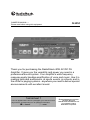
Thank you for purchasing the RadioShack 40W AC/DC PA
Amplifier. It gives you the versatility and power you need in a
professional sound system. Your amplifier’s wide frequency
response easily handles amplification of voice and music. Use it in
meeting halls and auditoriums, at sports events, in schools, and in
the office for paging systems - anywhere you need to deliver special
announcements with excellent sound.
+/2146#06
If an icon appears at the end of a paragraph, go to the box on that
page with the corresponding icon for pertinent information.
— Caution
± — Note
© 2004 RadioShack Corporation.
All Rights Reserved.
RadioShack and RadioShack.com
are trademarks used by
RadioShack Corporation.
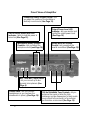
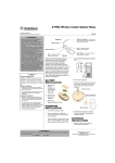
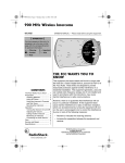
Front View of Amplifier
Phono/Aux Rotary Volume Control - lets
you adjust the volume of the turntable or
auxiliary sound source (See Page 15).
Output Power Level LED
Indicator - lets you monitor and
control the output power level
(See Page 15).
On/Off Rocker Switch with LED
Indicator - lights to indicate power is
turned on (See Page 15).
Microphone Rotary Volume
Controls - lets you adjust the
microphone level (see Page 15).
Rotary MASTER Volume
Control - lets you adjust the
overall sound level (See Page 15).
MIC 1 and MIC 2 Input Jacks
- let you connect up to two
dynamic microphones (See
Page 6).
Phones Jack - lets you connect
headphones so you can hear the
mixed audio in privacy (See Page 16).
2
100 Hz/1kHz/8kHz Tone Controls - let you
enhance the sound or tailor the high,
midrange, and low frequencies for each audio
source input to the acoustics of a particular
performance environment (See Page 15).
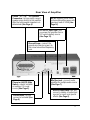
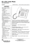
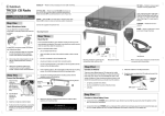
Rear View of Amplifier
COM/4Ω/8Ω/16Ω/70V Speaker
Connectors - let you easily connect
speaker wires directly to the amplifier
after the total speaker impedance is
determined (See Page 9).
AC IN - supports other music
instrument/amplifier power with
maximum load of 100W (See
Page 14).
DC 5A/12V Input Jack - lets
you power the amplifier from a
12V vehicle battery source
(See Page 15).
Ground Screw - connect the
ground wire (black or green) to
this screw to avoid low-frequency
hum.
Phono to AUX/CD Slide
Switch - selects turntable
or auxiliary CD sound
source (See Page 6).
Phono Jacks - let you
connect a turntable (See
Page 6).
Mix Bus Jack - connects extra
amplifier for multiple audio source
(See Page 7).
AUX/CD Input Jack - lets you
connect a variety of audio input
sources for music and special
effects (See Page 6).
3
%106'065
Preparation
Preparation ............................ 4
Placing the Amplifier .......... 4
Placing the Speakers ......... 4
Presetting the Controls ...... 4
Connections .......................... 5
Connecting Input Sources... 5
Connecting the Speakers..... 7
One Speaker ................... 9
Two Speakers in Series .. 9
Two Speakers in
Parallel .......................... 10
Series/Parallel Comb. ... 11
Speakers w/Transform. . 12
Connecting Power ............... 15
Connecting the DC Jack .... 15
Replacing the DC
Power Cord’s Fuse ............ 15
Operation ............................. 15
Monitoring Sound.............. 15
Listening Safely ................ 15
Troubleshooting ................... 16
Care ..................................... 17
Service and Repair .............. 17
Specifications ...................... 18
Accessories ........................... 19
24'2#4#6+10
2.#%+0)6*'#/2.+(+'4
Before you use your amplifier, be sure to place it on
a location with adequate ventilation. Do not put it on
thick carpeting (which can restrict air flow) or near a
heat source, such as a heat vent or radiator (which
can cause it to overheat).
2.#%+0)6*'52'#-'45
Speaker placement depends on your room’s size
and arrangement. We recommend you play a
wide-range recording and experiment with speaker
placement until you find the locations that result in
the best sound. For the best results, point the
speakers in toward the listeners, especially if you
place the speakers far apart so their coverage
areas overlap to prevent dead spots (areas not
covered by the speaker’s sound). Position the
speakers slightly above the level of the listeners’
heads and be sure you have determined the correct
speaker impedance (see “Connecting the
Speakers” on Page 7).
24'5'66+0)6*'%10641.5
Before you begin making connections or using your
amplifier, preset the audio input sources’ and
amplifier’s controls to avoid overdriving a channel or
producing loud sounds.
4
2TGUGVVKPIVJG#WFKQ+PRWV5QWTEGU
Set the audio input sources’ controls to these levels.
Audio Device
Control
Turntable
Power
Setting
Off
Tape Deck
Power
Off
CD Player
Power
Off
Amplifier
Receiver
Power
Tone
Off
Flat
2TGUGVVKPIVJG#ORNKHKGT
Control
Setting
Power
Out
MIC 1, MIC 2, PHONO/AUX
MIN
100 Hz, 1 kHz, 8 kHz
0dB (mid position)
MASTER VOLUME
MIN
Connections
Warning: To prevent possible hearing loss, set the
amplifier’s controls to the settings shown below.
After you turn on the amplifier or change the
program source, set the controls to a comfortable
listening level.
%100'%6+105
%100'%6+0)+02765174%'5
You can connect optional components, such as
microphones, tuners, turntables, or CD players to
your amplifier to expand your system. To prevent
hum and other noise, use low-capacitance shielded
cable. Your local RadioShack store carries a wide
selection of audio components and connecting
cable.
5
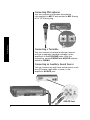
%QPPGEVKPI/KETQRJQPGU
You can connect one dynamic microphone
(not supplied) to MIC 1 and another to MIC 2 using
a 1/4” (6.35 mm) plug.
MIC 1
MIC 2
Connections
%QPPGEVKPIC6WTPVCDNG
You can connect a low level audio input source,
such as a magnetic cartridge turntable, to the
amplifier’s L and R PHONO jacks. With this
connection, set the PHONO and AUX/CD selector
switch to PHONO.
%QPPGEVKPICP#WZKNKCT[5QWPF5QWTEG
You can connect any high-level sound source, such
as a CD player, tape deck, or tuner, to the
amplifier’s AUX/CD jack.
AUX/CD Jack
6
%QPPGEVKPIVJG/+:$75,CEM
You can connect another MP-40 amplifier to this
jack (shown on page 3) to double the size of your
PA system. This lets you use up to four
microphones and two turntables
(or two auxiliaries) sound sources.
Use a shielded cable with phono plugs at each end
to connect the amplifier. Connect the cable between
the two amplifiers’ MIX BUS jacks. For the best
results, use the most appropriate cable length.
You can connect one or more 4-, 8- or 16-ohm
speakers to the amplifier, with or without
transformers. To ensure equal volume from each
speaker, all the connected speakers should have
the same impedance rating.
Proper phasing is important when you use more
than one speaker in the same room or area.
Out-of-phase speakers can lose up to one-half of
their potential volume, and can have a significantly
decreased bass effect ±.
Connections
%100'%6+0)6*'52'#-'45
±016'±
Proper phasing occurs when
speakers are set to allow
sound to flow in the same
direction.
Most speaker terminals are color-coded or have a
mark that indicates the terminal’s polarity. Usually,
terminals with positive polarity are red or have a
plus (+) symbol, and terminals with negative polarity
are black or have a minus (-) symbol. Phasing is
correct when you connect + to + and - to -.
%#76+10
&'6'4/+0+0)616#.52'#-'4
+/2'�%'
•
Before you connect speakers to the amplifier, you
must determine the total speaker impedance. •
To determine total speaker impedance, you must
first decide if you are connecting the speakers in
series, parallel, or a series/parallel combination.
A total speaker impedance
higher than 16 ohms or
lower than 4 ohms can
damage your amplifier.
When determining the total
speaker impedance, first
determine whether you are
connecting the speakers in
series, parallel, or a series/
parallel combination.
7
±016'±
For the best results when
connecting speakers
(in series or parallel), only
use speakers having the
same impedance.
Important: If you are connecting more than two
speakers in series only or parallel only, be sure the
total impedance does not exceed the amplifier’s
maximum impedance (16 ohms) or fall below the
minimum impedance (4 ohms). You can achieve a
proper total impedance by combining series and
parallel connections ±.
24'2#4+0)6*'52'#-'49+4'
±016'±
Connections
If you connect speakers
without transformers, the
speaker wire should be no
longer than 50 feet (See
“Connecting Speakers
with Transformers” on
page 13).
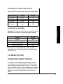
Use the shortest length of wire possible to connect
the speakers. After placing the speakers in the
desired location, determine the wire length and
choose the appropriate gauge size.±
Wire Length
Wire Gauge
25 feet or less
18-gauge
Over 25 feet
16-gauge
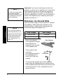
• Use a wire stripper
(not supplied) to remove
about half-inch of
insulation from the end
of the speaker wire.
• Then, attach a wire
connector
(not supplied) and twist
the exposed wire to
secure all of the wire
strands.
Wire Stripper
Wire
Connector
• To connect the speaker wire to the amplifier,
press down the appropriate push terminal lever
on the amplifier and insert the end of the wire into
the terminal’s hole. Then, release the lever to
secure the wire.
8
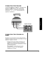
%100'%6+0)10'52'#-'4
Connections
Connect the speaker’s negative (-) terminal to the
amplifier’s COM terminal. Then, connect the
speaker’s positive (+) terminal to the speaker
terminal (4 Ω, 8 Ω, or 16 Ω) that matches the
speaker’s impedance.
Speaker Terminals
%100'%6+0)69152'#-'45+0
5'4+'5
Speakers are connected in series when the first
speaker’s positive terminal is connected to the next
speaker’s negative terminal.
• Determine the total speaker impedance of
speakers you want to connect in series by
adding up the individual impedances of all the
connected speakers.
For example: If connecting two 4-ohm
speakers in series, your total speaker
impedance is 8 ohms.
9
Connections
Follow these steps to connect speakers in series.
1. Connect the first speaker’s positive terminal to
the other speaker’s negative terminal.
2. Connect the first speaker’s negative terminal to
the amplifier’s COM terminal.
3. Connect the other speaker’s positive terminal
to the amplifier’s terminal (4 Ω, 8 Ω, or 16 Ω)
that matches the total speaker impedance.
%100'%6+0)69152'#-'45+0
2#4#..'.
Speakers are connected in parallel when all
speakers’ negative terminals are connected
together and all their positive terminals are
connected together.
• Determine the total speaker impedance of
speakers you want to connect in parallel by
dividing the impedance of one speaker by the
number of speakers.
For example: If connecting two 8-ohm
speakers in parallel, divide 8 (one speaker’s
impedance) by 2 (number of speakers). Your
total speaker impedance is 4.
10
Connections
Follow these steps to connect two speakers in
parallel.
1. Connect both speaker’s negative (-) terminals
to each other. Then, connect both wires to the
amplifier’s COM terminal.
2. Connect both speakers’ positive (+) terminals
to each other. Then, connect both wires to the
amplifier’s speaker terminal (4 Ω, 8 Ω, or 16 Ω)
that matches the total speaker impedance.
%100'%6+0)(17452'#-'45+0
5'4+'52#4#..'.%1/$+0#6+10
Follow these steps to combine series and parallel
combinations±.
1. Group the four speakers into two pairs.
2. Connect each pair of speakers in series. If you
connected 8-ohm speakers, the total
impedance of each pair is 16 ohms (8+8 = 16).
±016'±
If each of the four speakers
is 8 ohms, the total speaker
impedance of the combined
series/parallel connection
described at right is also 8
ohms. Likewise, the total
speaker impedance is 4 or
16 ohms if the speakers are
4 or 16 ohms, respectively.
11
3. Connect each pair of speakers in parallel. If
you connected 8-ohm speakers, the total
impedance of both pairs is 8 ohms (16/2 = 8).
4. Connect the speakers’ negative (-) terminals to
the amplifier’s COM terminal.
5. Connect the speakers’ positive (+) terminals to
the amplifier’s (4 Ω, 8 Ω, or 16 Ω) terminal that
matches the total speaker impedance, as
calculated in Step 3.
Connections
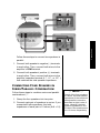
%100'%6+0)52'#-'459+6*
64#05(14/'45
For the best results when you connect two or more
speakers to your system, you can use a line
transformer (not included) for each speaker.
12
Transformers allow you to:
• connect speakers with different impedances
without causing output differences between the
speakers.
• add or remove a speaker from the system
without having to recalculate the entire
system’s impedance.
• reduce signal loss when you use speaker wire
over 50 feet (15.24 meters) long.
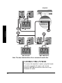
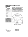
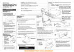
Follow these steps to connect the speakers with the
transformers. Example shown on next page.
1. Connect a wire from the amplifier’s 70V
terminal to the transformer’s desired primary
tap (10, 5, 2.5, 1.25 or 0.62 watts). ±
2. Connect a wire from the amplifier’s COM
terminal to the C (common) taps on the
transformer’s primary side.
3. Connect a wire from the speaker’s positive (+)
terminal to the transformer’s secondary tap that
matches the speaker’s total impedance
(4 Ω, 8 Ω, or 16 Ω).
%#76+10
•
•
Before you connect the
speakers, be sure the total
wattage of the primary tap
you use does not exceed
the amplifier’s maximum
40-watt output power
rating.
Avoid multiple connections
to the amplifier’s 70V and
COM terminals.
±016'±
Usually, a speaker in a
system uses the same
wattage tap. If you want a
particular speaker to have a
higher volume level, connect
the wire from the 70V terminal
to a higher wattage tap on its
transformer.
4. Connect a wire from the speaker’s negative (-)
terminal to the C (common) tap on the
transformer’s secondary side.
13
Connections
Line transformers have several connectors called
taps. The primary taps on one side of the
transformer are the inputs, and are rated in watts.
The secondary taps on the other side of the
transformer are the outputs, and are rated in
ohms.
Amplifier
Connections
Note: The wires labeled with an A are connected to each other.
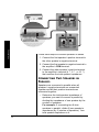
%100'%6+0)219'4
To connect the amplifier to power, plug the female
end of the supplied AC power cord into the
amplifier’s AC IN jack and the other end to any
standard AC outlet.
14
To power the amplifier from your vehicle’s 12V
battery, plug the supplied DC power cable’s barrel
plug to the DC 12V IN jack, and then connect the
other end to your vehicle’s 12V accessory socket,
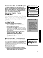
such as a cigarette-lighter socket. 4'2.#%+0)6*'&%219'4
%14& 5(75'
If the amplifier does not operate from a 12V battery
source, check the fuse in the cigarette lighter plug.
If the fuse is blown, remove the cap of the plug and
replace the fuse with the proper type and rating
(6A/250V).
12'4#6+10
Follow these steps to use your amplifier.
1. Set the ON/OFF switch to the ON position.
2. Start the input sound source.
3. Set MASTER VOLUME approximately to the
mid-position. The LEVEL indicator on the front
panel flashes from the left to the right showing
the sound level.
4. Adjust the following controls to the desired
volume and balance: MIC 1, MIC 2,
PHONO/AUX, 100Hz, 1kHz, 8 kHz
5. After you get the desired balance, adjust the
MASTER VOLUME to the desired volume
level.
/10+614+0)6*'5170&5174%'5
To monitor the sound sources, insert the 1/4-inch
(6.35 mm) plug of either mono or stereo headphone
(not supplied) into the amplifier’s PHONES jack ±.
Using headphones lets you easily check and adjust
the sound sources’ balance.
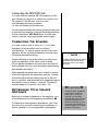
WARNING: To reduce the risk of fire or shock
hazard, do not expose this product to rain or
moisture.
..CAUTION..
RISK OF ELECTRIC SHOCK
DO NOT OPEN
!
CAUTION: TO REDUCE THE RISK OF ELECTRIC
SHOCK, DO NOT REMOVE COVER OR BACK. NO
USER-SERVICEABLE PARTS INSIDE. REFER
SERVICING TO QUALIFIED PERSONNEL.
The lightning symbol is intended to alert you to
the presence of uninsulated dangerous voltage
within this product’s enclosure that might be of
sufficient magnitude to constitute a risk of
electric shock. Do not open the product’s case.
!
The exclamation symbol is intended to inform
you that important operating and maintenance
instructions are included in the literature
accompanying this product.
%#76+10
• Your vehicle must have a
negative ground
electrical system. If you
are not sure, check with
your vehicle dealer.
• Unplug the AC power
cord before you connect
the DC power cable.
Likewise, disconnect the
DC power cable before
you plug in the AC power
cord.
Operation
Operation
%100'%6+0)6*'&%8+0,#%-
±016'±
<RXUORFDO5DGLR6KDFNVWRUH
FDUULHVDZLGHVHOHFWLRQRI
KHDGSKRQHV
.+56'0+0)5#('.;
To protect your hearing, follow these guidelines.
• Always start by setting the volume to the lowest
level possible before you begin listening.
15
• Put the headphones on, and then gradually
increase the volume to your desired listening
level.
Troubleshooting
• Do not listen at extremely high volume levels.
Extended high-volume listening can lead to
permanent hearing loss.
• Once you set the volume, do not increase it.
Over time, your ears adapt to the volume level,
so a volume level that does not cause
discomfort might still damage your hearing.
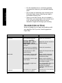
6417$.'5*116+0)
We do not expect you to have any problems with
your amplifier. But if you do, these suggestions
might help.
2TQDNGO
No power.
2QUUKDNG%CWUG
Sound source or speakers
not connected properly.
Amplifier’s MASTER
VOLUME, MIC 1, MIC 2,
PHONO/AUX, 100 Hz,
1kHz, 8 kHz controls set to
minimum.
No sound.
Feedback.
16
5QNWVKQP
Check all connections.
Adjust the volume control to
desired setting.
Sound source or speakers
are not connected properly.
Check all connections.
A microphone or cable
might be faulty.
Check all microphones and
cables.
The speaker’s wires might
be the wrong impedance.
Make sure all connected
speakers have the same
impedance rating.
The speaker’s wires might
be too small.
Make sure the speaker’s
wires are the correct gauge
according to length.
The amplifier might have
shut down.
Turn the amplifier off and let
it cool. Make sure the
amplifier is properly
ventilated, and then turn it
back on.
Microphones or speakers
are too close together.
Reposition the microphones
and speakers.
• Keep the amplifier dry; if it gets wet, wipe it dry
immediately.
• Use and store the amplifier only in room
temperature environments.
• Handle the amplifier carefully; do not drop it.
• Keep the amplifier away from dust and dirt, and
wipe it with a damp cloth occasionally to keep it
looking new.
Care
%#4'
5'48+%'#0&4'2#+4
If your amplifier is not performing as it should, take it
to your local RadioShack store for assistance. To
locate your nearest RadioShack, use the store
locator feature on RadioShack's website
(www.radioshack.com), or call 1-800-The Shack
(843-7422) and follow the menu options. Modifying
or tampering with the amplifier’s internal
components can cause a malfunction and might
invalidate its warranty.
17
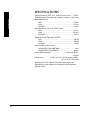
52'%+(+%#6+105
Output Power at THD 10%, 4-Ohm Load 1 kHz ....... 40W
Specifications
Total Harmonic Distortion (at 5 Watts, 4 ohms, 1 kHz, with
Band Pass Filter)
MIC................................................................... 0.50%
AUX.................................................................. 0.10%
PHONO ............................................................ 0.30%
Input Sensitivity (at 10%, THD, 1kHz)
MIC..................................................................2.5 mV
AUX................................................................150 mV
PHONO ............................................................3.5mV
Signal to Noise Ratio with A-WTD
MIC....................................................................60 dB
AUX...................................................................80 dB
PHONO .............................................................70 dB
Hum and Noise at 4 ohms
At MASTER VOLUME MIN ................................1 mV
At MASTER VOLUM MAX ...............................50 mV
Power Requirements................................120V AC 60 Hz
12VDC
Dimensions ............ 3 3/8 X 12 3/4 X 8 7/8 inches (HWD)
(8.5 X 32.4 X 22.6 cm)
Specifications are typical; individual units might vary.
Specifications are subject to change and improvement
without notice.
18
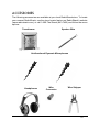
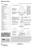
#%%'5514+'5
The following accessories are available at your local RadioShack store. To locate
your nearest RadioShack, use the store locator feature on RadioShack’s website
(www.radioshack.com), or call 1-800-The Shack (843-7422) and follow the menu
options.
Speaker Wire
Transformer
Unidirectional Dynamic Microphones
Headphones
Wire
Connector
Wire Stripper
19
Limited One-Year Warranty
This product is warranted by RadioShack against manufacturing defects in material and workmanship under normal use for one (1) year from the date of purchase from RadioShack companyowned stores and authorized RadioShack franchisees and dealers. EXCEPT AS PROVIDED
HEREIN, RadioShack MAKES NO EXPRESS WARRANTIES AND ANY IMPLIED WARRANTIES,
INCLUDING THOSE OF MERCHANTABILITY AND FITNESS FOR A PARTICULAR PURPOSE,
ARE LIMITED IN DURATION TO THE DURATION OF THE WRITTEN LIMITED WARRANTIES
CONTAINED HEREIN. EXCEPT AS PROVIDED HEREIN, RadioShack SHALL HAVE NO LIABILITY OR RESPONSIBILITY TO CUSTOMER OR ANY OTHER PERSON OR ENTITY WITH RESPECT TO ANY LIABILITY, LOSS OR DAMAGE CAUSED DIRECTLY OR INDIRECTLY BY USE
OR PERFORMANCE OF THE PRODUCT OR ARISING OUT OF ANY BREACH OF THIS WARRANTY, INCLUDING, BUT NOT LIMITED TO, ANY DAMAGES RESULTING FROM INCONVENIENCE, LOSS OF TIME, DATA, PROPERTY, REVENUE, OR PROFIT OR ANY INDIRECT,
SPECIAL, INCIDENTAL, OR CONSEQUENTIAL DAMAGES, EVEN IF RadioShack HAS BEEN
ADVISED OF THE POSSIBILITY OF SUCH DAMAGES.
Some states do not allow limitations on how long an implied warranty lasts or the exclusion or limitation of incidental or consequential damages, so the above limitations or exclusions may not apply
to you.
In the event of a product defect during the warranty period, take the product and the RadioShack
sales receipt as proof of purchase date to any RadioShack store. RadioShack will, at its option, unless otherwise provided by law: (a) correct the defect by product repair without charge for parts and
labor; (b) replace the product with one of the same or similar design; or (c) refund the purchase
price. All replaced parts and products, and products on which a refund is made, become the property of RadioShack. New or reconditioned parts and products may be used in the performance of
warranty service. Repaired or replaced parts and products are warranted for the remainder of the
original warranty period. You will be charged for repair or replacement of the product made after the
expiration of the warranty period.
This warranty does not cover: (a) damage or failure caused by or attributable to acts of God, abuse,
accident, misuse, improper or abnormal usage, failure to follow instructions, improper installation or
maintenance, alteration, lightning or other incidence of excess voltage or current; (b) any repairs
other than those provided by a RadioShack Authorized Service Facility; (c) consumables such as
fuses or batteries; (d) cosmetic damage; (e) transportation, shipping or insurance costs; or (f) costs
of product removal, installation, set-up service adjustment or reinstallation.
This warranty gives you specific legal rights, and you may also have other rights which vary from
state to state.
RadioShack Customer Relations, 200 Taylor Street, 6th Floor, Fort Worth, TX 76102
12/99
01A04
Printed in China
32-2054