1
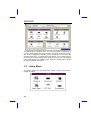
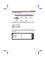
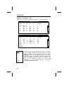
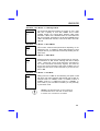
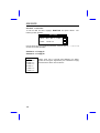
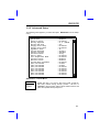
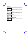
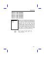
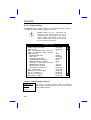
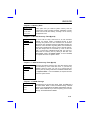
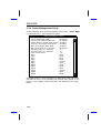
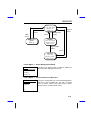
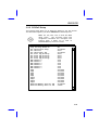
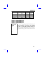
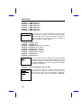
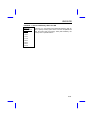
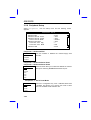
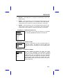
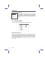
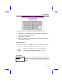
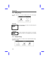
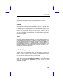
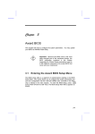
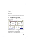
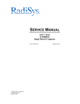
Chapter 3
AMI BIOS
This chapter tells how to configure the system parameters. To update the
BIOS ,refer to section "BIOS Flash Utility".
Important: Because the BIOS code is the most
often changed part of the mainboard design, the
BIOS information contained in this chapter
(especially the Chipset Setup parameters) may be
a little different compared to the actual BIOS that
came with your mainboard.
3.1
Entering the AMI BIOS Setup
BIOS setup utility is a segment of code/routine resides in the BIOS Flash
ROM. This routine allows you to configure the system parameters and save
them into 128 bytes CMOS area , (normally in the RTC chip or directly in the
main chipset). To enter the BIOS Setup, press <Del> during POST (Power-On
Self Test). The BIOS Setup Main Menu appears as shown below.
3-1
AMI BIOS
The AMI BIOS is in Windows form. You can use either the keyboard or a
mouse to move between the items. To select among the Setup menu groups,
use <Tab> to highlight the selected group or simply click on the icon of the
selected Setup menu. To select among the options, you can either use the
arrow keys to move the highlight bar or simply click on the icon of the desired
option. After making your selection, press <Enter> or double-click on the icon
to open the selected menu option.
3.2
Setup Menu
The screen below shows the Setup menu window. Use the arrow keys to
highlight an option.
3-2
AMI BIOS
3.2.1 Standard Setup
The following screen appears if you select Standard from the Setup options:
This Standard Setup menu allows you to setup basic information of hard disk,
data/time and floppy. For hard disk parameters, choose any of following:
Standard --> Pri Master
Standard --> Pri Slave
Standard --> Sec Master
Standard --> Sec Slave
These items are setting of onboard IDE primary and secondary channel, each
channel supports two IDE devices which are connected as master and slave.
Refer to section 2.3 "Connectors" of how to connect them. The example below
is for Pri Master.
Primary Master Hard Disk
Type
LBA/Large Mode
Block Mode
32Bit Mode
PIO Mode
:
:
:
:
:
Auto
Off
Off
Off
Auto
3-3
AMI BIOS
Standard --> Pri Master --> Type
When move cursor bar to Type and press <Enter> , this menu appears:
Hard Disk Types
Type
Cyl
Hd
Not Installed
1
306
4
2
615
4
3
615
6
4
940
8
5
940
6
WP
Sec
Size(MB)
128
300
300
512
512
17
17
17
17
17
10
20
31
62
47
or
Hard Disk Types
Type
Cyl
Hd
WP
Sec
Size(MB)
43
44
45
46
User
Auto
CDROM
830
830
917
1224
7
10
15
15
512
65535
65535
65535
17
17
17
17
48
69
114
152
Type
Not Installed
1
2
...
46
User
Auto
CDROM
3-4
This item lets you set the IDE device type that your system
supports. Default is Auto to automatically detect the installed
HDD or CDROM at POST (Power-On Self Test). Select
CDROM if you have a CDROM installed in your system.
Select type 1~46 if your HDD has parameters listed on the
table. Select User if your HDD is not on the table and you
prefer to enter parameters manually. Set this to Not
Installed if no HDD connected. Normally, use Auto is
enough for all kinds of conditions.
AMI BIOS
Standard --> Pri Master --> LBA/Large Mode
LBA/Large
Off
On
The enhanced IDE feature allows the system to use a hard
disk with a capacity of more than 528MB. This is made
possible through the Logical Block Address (LBA) mode
translation. LBA is now a standard feature of current IDE hard
disk on the market, because they are all above 528MB. Note if
HDD is formatted with LBA On, it will not be able to boot with
LBA Off.
Standard --> Pri Master --> Block Mode
Block
Off
On
This function enhances disk performance depending on the
hard disk in use. If enabled, it allows data transfers in block
(multiple sectors), and eliminate the interrupt handling time for
each sector.
Standard --> Pri Master --> 32Bit Mode
32Bit
Off
On
Enabling this item improves system performance by using 32bit instructions for disk access. Although IDE bus is always
16-bit, chipset will convert 32-bit instruction (command) to
two 16-bit commands continuously together, and save the
time to give second command. Note some old HDDs can not
support too close of two 16-bit commands, if you are not sure,
set it to Off.
Standard --> Pri Master --> PIO Mode
PIO
Auto
0
1
2
3
4
Setting this item to Auto for auto-detecting the speed of hard
disk drive. PIO mode represents data transfer rate of HDD, for
example mode 0 is 3.3MB/s, mode 1 is 5.2MB/s, mode 2 is
8.3MB/s, mode 3 is 11.1MB/s and mode 4 is 16.6MB/s. In
some cases, if your hard disk is unstable, you may manually
try the slower mode.
Caution: The first IDE drive on each channel is
recommended at far end side of cable. Refer
to section 2.3 "Connectors" for detail.
3-5
AMI BIOS
Standard --> Data/Time
To set the date and time, highlight Date/Time and press <Enter>. The
following screen appears:
Date/Time
Date : Thu, Nov 7, 1996
+
Time : 14:26:09
-
Use the arrow keys to move among the items. Press or click on < +> or < -> to
set the current time and date.
Standard --> Floppy A
Standard --> Floppy B
Floppy A
Not Installed
360KB 5.25"
1.2MB 5.25"
720KB 3.5"
1.44MB 3.5"
2.88MB 3.5"
3-6
Floppy drive type is normally auto-detected, the setting
shown left are types supported by this mainboard. Floppy
drive B has the same menu as drive A.
AMI BIOS
3.2.2 Advanced Setup
The following items appear if you select the option Advanced from the Setup
menu:
Advanced Setup
Quick Boot
Power-On Delay
BootUp Sequence
BootUp Num-Lock
Floppy Drive Swap
Floppy Drive Seek
Typematic Rate
System Keyboard
Primary Display
Password Check
Parity Check
OS/2 Compatible Mode
Internal Cache
External Cache
System BIOS Cacheable
C000,16k Shadow
C400,16k Shadow
C800,16k Shadow
CC00,16k Shadow
D000,16k Shadow
D400,16k Shadow
D800,16k Shadow
DC00,16k Shadow
:
:
:
:
:
:
:
:
:
:
:
:
:
:
:
:
:
:
:
:
:
:
:
Enabled
Disabled
A:,C:,CDROM
Off
Disabled
Disabled
30
Present
VGA/EGA
Setup
Disabled
Disabled
Enabled
Enabled
Disabled
Cached
Cached
Disabled
Disabled
Disabled
Disabled
Disabled
Disabled
Advanced --> Quick Boot
Quick Boot
Disabled
Enabled
Enable this item if you want to skip some POST (Power-On
Self Test) routines during boot-up process. Set this to
Disabled to let the system perform all the POST routines and
follow the specified bootup sequence.
3-7
AMI BIOS
Advanced --> Power-on Delay
Power-On
Delay
Disabled
2
3
...
15
This item lets you set the waiting time before system boot.
Some large HDDs need more time for spindle motor to be
stabilize and ready for data access. The settings are from 2
to 15 seconds.
Advanced --> BootUp Sequence
BootUp Sequence
A:,C:,CDROM
A:,CDROM,C:
C:,A:,CDROM
C:,CDROM,A:
CDROM,A:,C:
CDROM,C:,A:
The bootup sequence allows you to specify the system
boot search sequence. If you need to boot from
CDROM, you may set the CDROM as the first priority.
The default is A:, C:, CDROM, but after you have
installed your operating system, we recommend to
use C:,A:,CDROM, which prevents accidentally
boot virus affected diskette.
Advanced --> BootUp Num-Lock
BootUp Num-Lock
Off
On
Setting this item to On enables the numeric function of
the numeric keypad. Disabling the numeric function
allows you to use the cursor control keypad (arrow).
Advanced --> Floppy Drive Swap
Floppy Drive Swap
Disabled
Enabled
This item allows you to swap floppy drives. For
example, if you have two floppy drives (A and B), you
can assign the first drive as drive B and the second
drive as drive A or vice-versa.
Advanced --> Floppy Drive Seek
Floppy Drive Seek
Disabled
Enabled
3-8
When enabled, the BIOS issues seek command to
floppy during POST, to move floppy drive head forward
and backward.
AMI BIOS
Advanced --> Typematic Rate
Typematic Rate
Disabled
15
20
30
This item allows you to control the speed of repeated
keystrokes. The default is 30 characters/sec .
Advanced --> System Keyboard
System Keyboard
Absent
Present
If there is a keyboard connected to the system, set this
item to Present . Otherwise, POST will bypass the
keyboard test if select Absent.
Advanced --> Primary Display
Primary Display
Absent
VGA/EGA
CGA40x25
CGA80x25
Mono
This function selects the type of video card in use. The
default setting is VGA/EGA. Because current PCs are
almost all VGA only, this item becomes almost
useless.
Advanced --> Password Check
Password Check
Setup
Always
This item lets you set when to check for the password.
When set to Always, a password prompt appears
every time you turn-on the computer or when you enter
Setup. When set to Setup, the password prompt
appears when you try to enter Setup.
Advanced --> Parity Check
Parity Check
Disabled
Enabled
Set this item to Enabled if you install SIMMs with
parity in your system. Otherwise, set this item to
Disabled . Since the DRAM can still operate without
enabling the parity scheme for SIMMs with parity, this
function is normally set to Disabled.
3-9
AMI BIOS
Advanced --> OS/2 Compatible Mode
OS/2 Compatible
Mode
Disabled
Enabled
Enable this item if your system is utilizing an OS/2
operating system and has a memory size of more than
64 MB.
Advanced --> Internal Cache
Internal Cache
Disabled
Enabled
This function lets you enable or disable the internal
cache (The cache within CPU).
Advanced --> External Cache
External Cache
Disabled
Enabled
This function lets you enable or disable the external
cache (The PBSRAM cache on the mainboard).
Advanced --> System BIOS Cacheable
System BIOS
Cacheable
Disabled
Enabled
3-10
Enabling this item allows you to cache the system
BIOS to further enhance system performance.
AMI BIOS
Advanced --> C000, 16K Shadow
Advanced --> C400, 16K Shadow
Advanced --> C800, 16K Shadow
Advanced --> CC00, 16K Shadow
Advanced --> D000, 16K Shadow
Advanced --> D400, 16K Shadow
Advanced --> D800, 16K Shadow
Advanced --> DC00, 16K Shadow
C000,16K Shadow
Disabled
Enabled
Cached
These items are for the shadow and cacheable option of
ROM code on the expansion cards (including VGA). The
shadow means to copy ROM code into faster DRAM and
hence improves the execution performance of these
ROM code. Cache them will further improve the
performance but there are some cards have
incompatible problem if cache its ROM code. You need
to know the specific addresses of the ROM code, for
example, VGA BIOS occupies segment C000 and C400,
so that the default of C000 and C400 are Cached. If you
do not know this information, enable all the ROM
shadow settings.
This ensures shadowing of any
present ROMs and reduces the available memory.
Note: The F000 and E000 segments are
always shadowed because BIOS code
occupies these area.
3-11
AMI BIOS
3.2.3 Chipset Setup
The Chipset Setup includes settings for the chipset dependent features,
especially the features related to system performance.
Caution: Make sure you understand the
meaning of each setting before you try to
change anything. The settings in this section
improve system performance but may cause
system unstable if the setting are not correct
for your system configuration.
Chipset Setup
430HX Global Features
Memory Hole
8Bit I/O Recovery Time (Sysclk)
16Bit I/O Recovery Time (Sysclk)
DRAM Timings
DRAM Refresh Rate
ISA Clock
Turbo Read Leadoff
DRAM Read Burst Timing
DRAM Write Burst Timing
Fast RAS to CAS Delay (clocks)
DRAM Leadoff Timing
Speculative Leadoff
Turn-Around Insertion
Peer Concurrency
Memory Error Check Mode
PCI 2.1 Compliant
USB Host Controller
USB Legacy Support
:
:
:
:
:
:
:
:
:
:
:
:
:
:
:
:
:
:
:
Disabled
Disabled
4
1
60ns
66 Mhz
PCICLK/4
Disabled
x333
x222
3
6/5/3/4
Enabled
Disabled
Disabled
Disabled
Disabled
Disabled
Disabled
Chipset --> 430HX Global Features
430HX Global
Features
Disabled
Enabled
3-12
This option is a global control to enable or disable the
430HX chipset enhancement features. The Turbo default
setting enables this item.
AMI BIOS
Chipset --> Memory Hole
Memory Hole
Disabled
512K-640K
15M-16M
This option lets you reserve system memory area for
special ISA cards. Chipset accesses code/data of these
area from the ISA bus directly, normally it is for memory
mapped I/O card.
Chipset --> 8Bit I/O Recovery Time Sysclk)
(
8Bit I/O
Recovery Time
(Sysclk)
Disabled
8
1
2
3
4
5
6
7
For some old I/O chips, when there is an I/O command
finished, the device needs a specified amount of time
(recovery time) before next I/O command can be started.
Because of new generation CPU and mainboard chipset, the
assertion of I/O command is getting faster, and sometimes
shorter than specified I/O recovery time of old I/O devices.
This item delays 8-bit I/O command by count of ISA bus
clock, if you find any unstable 8-bit I/O card, you may try to
extend the I/O recovery time by setting of this item. The
BIOS default value is 4 system clocks. If set to Disabled,
the chipset will insert 3.5 system clocks.
Chipset --> 16Bit I/O Recovery Time Sysclk)
(
16Bit I/O
Recovery Time
(Sysclk)
Disabled
4
1
2
3
The same as 8-bit I/O recovery time. This item delays 16-bit
I/O command by count of ISA bus clock, if you find any
unstable 16-bit I/O card, you may try to extend the I/O
recovery time by setting of this item. The BIOS default value
is 1 system clocks . If set to Disabled, the chipset will auto
insert 3.5 system clocks.
Chipset --> DRAM Timings
DRAM Timings
Manual
60ns
70ns
The selections for this item are 60ns, 70ns, and Manual . If
you select either 60ns or 70ns, the DRAM Timing subitems
become non-configurable since BIOS automatically sets the
values. Select Manual if you want to specify your own item
settings. The BIOS default is 60ns.
3-13
AMI BIOS
Warning: The default memory timing setting is
60ns to get the optimal performance. Because
the specification limitation of chipset, 70ns
SIMM can only be used with CPU external
clock 60MHz or below. To use 70ns SIMM
with 66MHz CPU external clock may result in
unstable system behavior.
Chipset --> DRAM Refresh Rate
DRAM Refresh
Rate
50 Mhz
60 Mhz
66 Mhz
This option lets you specify the clock frequency at which the
chipset refreshes the DRAM to avoid data lost. The setting
is normally equal to CPU bus clock (external clock).
Chipset --> ISA Clock
ISA Clock
PCICLK/4
PCICLK/3
This option specifies the ISA bus clock frequency. The
selections are PCI bus clock divide by 4 or PCI clock divide
by 3, PCI clock is the half of CPU bus clock, for example,
66Mhz CPU bus clock has 33Mhz PCI bus clock, and the
ISA bus clock should be 33M/4= 8.25Mhz, The ISA bus
clock must be near 8Mhz.
Chipset --> Turbo Read Leadoff
Turbo Read
Leadoff
Disabled
Enabled
This item is reserved for cacheless configuration only. When
enabled, chipset bypasses the first data input of the DRAM
data pipeline buffer. Therefore, reduces one clock of DRAM
read leadoff timing. The default is Disabled.
Warring: "Turbo Read Leadoff" can only be
enabled for cacheless system or external cache
disabled.
3-14
AMI BIOS
Chipset --> DRAM Read Burst Timing
DRAM Read
Burst Timing
x444
x333
The Read Burst means to read four continuous memory
cycles on four predefined addresses from the DRAM. The
default value of 60ns FPM (Fast Page Mode) DRAM is x333
which means the 2nd,3rd and 4th memory cycles are 3 CPU
clocks. For EDO DRAM, the chipset will automatically
reduce one clock, that is, x444 becomes x333 and x333
becomes x222. The value of x is the timing of first memory
cycle and depends on the "DRAM Leadoff Timing" setting
Chipset --> DRAM Write Burst Timing
DRAM Write
Burst Timing
x444
x333
x222
The Write Burst means to write four continuous memory
cycles on four predefined addresses to the DRAM. This item
sets the DRAM write timing of the 2nd,3rd and 4th memory
cycles. There is no difference of EDO and FPM DRAM on
the write burst timing. The value of x depends on the "DRAM
Leadoff Timing" setting
Chipset --> Fast RAS to CAS Delay (clocks)
Fast RAS to
CAS Delay
(clocks)
3
2
This option specifies the wait state between the DRAM row
address strobe (RAS) and column address strobe (CAS)
signals. The default setting is 3 clocks.
Chipset --> DRAM Leadoff Timing
DRAM Leadoff
Timing
7/6/3/4
6/5/3/4
7/6/4/5
6/5/4/5
The Leadoff means the timing of first memory cycle in the
burst read or write. Actually, this setting includes not only
read/write leadoff timing but also the clocks of RAS
precharge and width of refresh RAS signal. The four digital
represent Read Leadoff/ Write Leadoff/ RAS Precharge/
Refresh RAS Width. For example, default is 6/5/3/4, which
means you have 6xxx DRAM read and 5xxx DRAM write,
with 3 clocks RAS precharge and 4 clock refresh RAS width.
3-15
AMI BIOS
Chipset --> Speculative Leadoff
Speculative
Leadoff
Disabled
Enabled
Enable this item reduce one clock of DRAM read leadoff
timing by presenting the DRAM read request before the
controller chip decodes the final memory target (i.e., cache,
DRAM or PCI). For example, the DRAM read timing of 60ns
EDO is 6-2-2-2, Enable this option improve DRAM read
timing to 5-2-2-2.
Chipset --> Turn-Around Insertion
Turn-Around
Insertion
Disabled
Enabled
Enabling this option allows the chipset to insert one turnaround clock cycle to the memory data bus for back-to-back
memory read and write cycles. If you have large loading on
the memory data bus, for example, four SIMMs with many
DRAM chips on the SIMM, this option provides a safety time
for data bus to switch direction.
Chipset --> Peer Concurrency
Peer
Concurrency
Disabled
Enabled
Peer Concurrency enables the CPU to run DRAM or cache
cycle while PCI master is accessing PCI target (slave),
however, the CPU to/from PCI bus will still be blocked. If
Disabled, the CPU will always be blocked when PCI master
owns the PCI bus. This function is useful if you have heavy
loading PCI masters on your system (such as PCI SCSI or
Network card).
Chipset --> Memory Error Check Mode
Memory Error
Check Mode
Disabled
Parity
ECC
3-16
This item selects the memory error check mode. The parity
mode uses 1 parity bit for each byte, each time the memory
data is updated, parity bit will be adjusted to have even
count "1" for each byte. When next time, if memory is read
with old number of "1", the parity error is occurred and this
is called single bit error detection. The ECC mode needs 8
ECC bit for 64 bit data, ECC bits are updated and checked
by special algorithm, the ECC algorithm has the ability to
detect double bit error and automatically correct single bit
error.
AMI BIOS
Tip: Because 36 bit SIMM has 4 bit more for
parity, the ECC mode can be supported by two
traditional parity SIMMs, it is no need to have
special ECC SIMM.
Chipset --> PCI 2.1 Compliant
PCI 2.1
Comliant
Disabled
Enabled
This item lets you control the Passive Release or Delayed
Transaction function of the PIIX3 chipset (Intel PCI to ISA
bridge). Enable it complies with the PCI revision 2.1. Try to
enable or disable it, if you have ISA card compatibility
problem.
Chipset --> USB Host Controller
USB Host
Controller
Disabled
Enabled
This item lets you enable or disable the USB function in
chipset. The mainboard acts as USB host, and you can plug
USB devices on the USB connector of back panel. You need
USB driver to support USB devices, normally, they are
provided by USB device vendors or operating system such
as Win95.
Important: The USB function shares INTD with
PCI slot 4. Therefore, if you enable the USB
function, only PCI cards that do not require IRQ,
such as VGA, can be installed in slot 4. The
PnP BIOS assigns an IRQ to VGA only if the
VGA requests for it.
Chipset --> USB Legacy Support
USB Legacy
Support
Disabled
Enabled
This item lets you enable or disable the USB keyboard
driver within the onboard BIOS. The keyboard driver
simulates legacy keyboard command and let you use USB
keyboard during POST or after boot if you don't have USB
driver in the operating system.
Caution: You can not use both USB driver and
USB legacy keyboard at the same time.
Disable "USB Legacy Support" if you have
USB driver in the operating system.
3-17
AMI BIOS
3.2.4 Power Management Setup
To take advantage of the power-management feature, select
from the Setup menu. The following items appear:
Power Mgmt
Power Management Setup
Power Management/APM
:
Instant-On Timeout (Minute)
:
Green Monitor Power Down State:
Display Card Power Down Mode :
Hard Disk Power Down Mode
:
Hard Disk Time Out (Minute)
:
Standby Time Out (Minute)
:
Suspend Time Out (Minute)
:
Slow Clock Ratio
:
IRQ3
:
IRQ4
:
IRQ5
:
IRQ7
:
IRQ8
:
IRQ9
:
IRQ10
:
IRQ11
:
IRQ12
:
IRQ13
:
IRQ14
:
IRQ15
:
Disabled
Disabled
Standby
Standby
Suspend
Disabled
10
10
1:8
Both
Both
Both
Both
Ignore
Both
Both
Both
Both
Ignore
Both
Both
The states transition of power management is shown below. Note that monitor
and HDD can be on or off at Standby and Suspend state, depend on the
setting in "Green Monitor Power Down State" and "Hard Disk Power Down
Mode":
3-18
AMI BIOS
Full Power On
HDD Timer
Timout
HDD
Activies
CPU: full speed
Monitor: on
HDD : on
Standby Timer
Timout
Activies
HDD Power
Down
HDD: off
Suspend
Switch
Standby
CPU: slow speed
Monitor: on/off
HDD: on/off
Suspend Timer
Timout
Activies
Suspend
CPU: stop
Monitor: on/off
HDD: on/off
Power Mgmt --> Power Management/APM
Power
Management/APM
Disabled
Enabled
Instant-On
This item is the global control to enable or disable the
advanced power-management function.
Power Mgmt --> Instant-OnTimeout (Minutes)
Instant-On Timeout
(Minutes)
Disabled
1
.....
15
This item is configurable only if the Power Management/
APM item is set to Instant On . This lets you specify
when to resume system power after being in powersaving mode for a certain period of time.
3-19
AMI BIOS
Power Mgmt --> Green Monitor Power Down State
Green Monitor
Power Down State
Standby
Suspend
Off
This function lets you select at which state to power
down your monitor. BIOS blanks the screen and power
down the monitor by special signal (VSYNC, HSYNC) on
the monitor connector. You need DPMS (Display Power
Management Standard) monitor to support power down
function.
Power Mgmt --> Display Card Power Down Mode
Display Card Power
Down State
Disabled
Standby
Suspend
This option allows you to select at which state to power
down your system display card. You need display card
which supports power down command for this function.
Power Mgmt --> Hard Disk Power Down Mode
Hard Disk Power
Down State
Disabled
Standby
Suspend
This option allows you to select at which state to power
down your IDE hard disk. The reduction of power
consumption is achieved by shutting down the spindle
motor of HDD. You need HDD which supports power
down command for this function.
Power Mgmt --> Hard DiskTimeout (Minutes)
Hard Disk Timeout
(Minute)
Disabled
1
.....
15
3-20
This option lets you set the time of your IDE hard disk to
go into power down state (spindle motor off) when there
is no hard disk activities. This item is independent with
the power state described above (Standby and
Suspend).
AMI BIOS
Power Mgmt --> StandbyTimeout (Minutes)
Standby Timeout
(Minute)
Disabled
1
.....
15
This item lets you set the time of your system to go into
Standby power down state when there is no system
activities. In Standby state, CPU clock is slowdown
according to the ratio set in "Slow Clock Ratio" below.
Any event detected returns the system to full power. The
system activity(or event) is detected through monitoring
of IRQ signals.
Power Mgmt --> SuspendTimeout (Minutes)
Suspend Timeout
(Minute)
Disabled
1
.....
15
This item lets you set the time (after Standby) to go into
Suspend power down state when there is no system
activities. System goes to Standby first and then goes to
Suspend state. In Suspend state, CPU clock is stopped.
Any event detected returns the system to full power. The
system activity(or event) is detected through monitoring
of IRQ signals.
Power Mgmt --> Slow Clock Ratio
Slow Clock Ratio
1:1
1:2
1:4
1:8
1:16
1:32
1:64
1:128
When the system enters the Standby state, the CPU
clock count in a giving time (not frequency) is reduced
by the ratio set in this item, actually, the period per CPU
clock is not changed. For example, 30ns clock period of
66MHz CPU clock is not changed at Standby state,
chipset generates STPCLK (stop clock) signal
periodically to prevent CPU for accepting clock from
clock generator. For full power on, the CPU can receive
66M count in one second, but if the ratio is set at 1:2, the
CPU will only receive 33M clock count in one second at
Standby state. This will effectively reduce CPU speed as
well as CPU power. This method is also known as Clock
Throttling.
3-21
AMI BIOS
Power Mgmt --> IRQ3 (COM2)
Power Mgmt --> IRQ4 (COM1)
Power Mgmt --> IRQ5 (Network/Sound or Others)
Power Mgmt --> IRQ7 (Printer or Others)
Power Mgmt --> IRQ8 (RTC)
Power Mgmt --> IRQ9 (Video or Others)
Power Mgmt --> IRQ10 (SCSI or Others)
Power Mgmt --> IRQ11 (SCSI or Others)
Power Mgmt --> IRQ12 (PS/2 Mouse or Others)
Power Mgmt --> IRQ13 (Floating Point of CPU)
Power Mgmt --> IRQ14 (IDE1)
Power Mgmt --> IRQ15 (IDE2)
IRQ3
Ignore
Monitor
WakeUp
Both
The system activities are monitored through the specified IRQ
signals to determine the transition of power state. Set
parameter to Monitor allows system to monitor the IRQ and
wait for timeout to go into Standby or Suspend state. Set
parameter to WakeUp allows system to back to full power if
the activity associated with this IRQ is detected. Both has
function of both Monitor and WakeUp.,
Note: The system activities listed above are general PC
standard, special card may require special IRQ, refer to card
manual for correct IRQ setting. You may also refer to Win95
"Device Manager" for which IRQ is assigned to which
device.
Important: The IRQ8 is fixed for RTC and IRQ13 is fixed for
floating point. They are recommended to set at Ignore. If
IRQ8 is not Ignore, OS/2 may fail to go into
Standby/Suspend, because of the periodically RTC interrupt.
Important: Network workstation will periodically receive the
polling command from network server, if the IRQ of network
card (normally IRQ5 or IRQ3) is not set to Ignore, the
system may fail to go into Standby/Suspend
3-22
AMI BIOS
3.2.5 PCI/PnP Setup
The PCI/PnP Setup allows you to specify the setting for your PCI devices.
The items below appear if you select PCI/PnP from the Setup menu.
Note: You can press <Ins> to enter the BIOS
Setup screen.
This procedure resets PnP
configuration information and reconfigure PnP
resource again, it allows you to solve an
IRQ/DMA/Memory resources conflict.
PCI/PnP Setup
Plug and Play Aware OS
PCI VGA Palette Snoop
PCI IDE Card
PCI IDE Primary IRQ
PCI Slot1 IRQ Priority
PCI Slot2 IRQ Priority
PCI Slot3 IRQ Priority
PCI Slot4 IRQ Priority
DMA Channel 0
DMA Channel 1
DMA Channel 3
DMA Channel 5
DMA Channel 6
DMA Channel 7
IRQ3
IRQ4
IRQ5
IRQ7
IRQ9
IRQ10
IRQ11
IRQ14
IRQ15
Reserved Memory Size for ISA
Reserved Memory Base for ISA
:
:
:
:
:
:
:
:
:
:
:
:
:
:
:
:
:
:
:
:
:
:
:
:
:
No
Disabled
Auto
Disabled
Auto
Auto
Auto
Auto
PnP
PnP
PnP
PnP
PnP
PnP
PCI/PnP
PCI/PnP
PCI/PnP
PCI/PnP
PCI/PnP
PCI/PnP
PCI/PnP
PCI/PnP
PCI/PnP
Disabled
C8000
3-23
AMI BIOS
PCI/PnP --> Plug and Play Aware O/S
Plug and Play
Aware O/S
No
Yes
Normally the PnP resource is allocated by BIOS during
POST (Power-On Self Test). If you are using PnP operating
system (such as Windows 95), you may set this item to
Yes, which informs BIOS to configure only the resources
needed for boot (VGA/IDE or SCSI). The rest of system
resources will be allocated by PnP operating system.
PCI/PnP --> PCI VGA Palette Snoop
PCI VGA
Palette Snoop
Disabled
Enabled
Enable this item informs the PCI VGA card to be quiet
preventing conflict when the palette register is updated
(accept data without responding any communication
signals). This is only useful for two display cards use the
same palette address and plugged on the PCI bus together
(such as MPEQ or Video capture), one is set to be quiet and
the other is set to act normally.
PCI/PnP --> PCI IDE Card
PCI IDE Card
Auto
Slot1
Slot2
Slot3
Slot4
Some old PCI IDE add-on cards are not fully PnP
compatible. You need to specify the slot you are using for
BIOS to configure correct PnP resources. This function
allows you to select the PCI slot for any of PCI IDE add-on
card present. Set this item to Auto to automatically
configure the installed PCI IDE card.
PCI/PnP --> PCI IDE Primary IRQ
PCI/PnP --> PCI IDE Secondary IRQ
PCI IDE
Primary IRQ
Disabled
INTA
INTB
INTC
INTD
Hardwired
3-24
These two items are in conjunction with "PCI IDE Card" to
decide IRQ routing of the primary or secondary channel of
the PCI IDE add-on card (not the onboard IDE). Each PCI
slot has 4 PCI interrupts aligned as the table below, you
have to specify the slot in "PCI IDE Card" above and choose
the PCI interrupt ( INTx) according to the interrupt
connection on the card. There are also cards support legacy
mode only, which is, connect IRQ directly through small
extension card on ISA bus, not through PCI interrupt. In
such case, select Hardwired.
AMI BIOS
PCI Slot
Location 1
Location 2
Location 3
Location 3
(pin A6)
(pin B7)
(pin A7)
(pin B8)
Slot 1
INTA
INTB
INTC
INTD
Slot 2
INTB
INTC
INTD
INTA
Slot 3
INTC
INTD
INTA
INTB
Slot 4
INTD
INTA
INTB
INTC
Slot 5 (if any)
INTD
INTA
INTB
INTC
PCI/PnP --> PCI Slot1 IRQ Priority
PCI/PnP --> PCI Slot2 IRQ Priority
PCI/PnP --> PCI Slot3 IRQ Priority
PCI/PnP --> PCI Slot4 IRQ Priority
PCI Slot1 IRQ
Priority
Auto
None
3
4
5
7
9
10
11
12
These items let you specify the preferred IRQ priority for
each PCI slot. PnP BIOS will assign the IRQ to each slot
according to the priority of these settings. Set to Auto for
PnP BIOS to configure IRQ automatically without any
priority preferred. Set to None if you does not want PnP
BIOS to allocate any IRQ for this slot (such as VGA card).
Set to specific IRQ if you prefer this IRQ for this card on this
slot.
3-25
AMI BIOS
PCI/PnP --> DMA Channel 0
PCI/PnP --> DMA Channel 1
PCI/PnP --> DMA Channel 3
PCI/PnP --> DMA Channel 5
PCI/PnP --> DMA Channel 6
PCI/PnP --> DMA Channel 7
DMA Channel 0
PnP
ISA
If your ISA card is not PnP compatible and needs special
DMA channel to support its function, specify the DMA
channel as ISA, which informs PnP BIOS to reserve this
DMA channel for the this legacy ISA card. The default is
PnP. PCI card has no DMA channel.
PCI/PnP --> IRQ3 (COM2)
PCI/PnP --> IRQ4 (COM1)
PCI/PnP --> IRQ5 (Network/Sound or Others)
PCI/PnP --> IRQ7 (Printer or Others)
PCI/PnP --> IRQ9 (Video or Others)
PCI/PnP --> IRQ10 (SCSI or Others)
PCI/PnP --> IRQ11 (SCSI or Others)
PCI/PnP --> IRQ14 (IDE1)
PCI/PnP --> IRQ15 (IDE2)
IRQ3
PCI/PnP
ISA
If your ISA card is not PnP compatible and needs special IRQ
to support its function, specify the IRQ as ISA, which informs
PnP BIOS to reserve this IRQ for the this legacy ISA card.
The default is PCI/PnP. PCI card are always PnP compatible
(except old PCI IDE card).
PCI/PnP --> Reserved Memory Size for ISA
Reserved
Memory Size
for ISA
Disabled
16K
32K
64K
3-26
If your ISA card is not PnP compatible and needs special
memory space to support its function, specify the memory
size in this item, which informs PnP BIOS to reserve the
memory space for legacy ISA card. The default is Disabled.
AMI BIOS
PCI/PnP --> Reserved Memory Base for ISA
Reserved
Memory Base
for ISA
C0000
C4000
C8000
CC000
D0000
D4000
D8000
DC000
This item is in conjunction with "Reserved Memory Size for
ISA" to specify memory space of the non-PnP compatible ISA
card. This item sets the memory base (start address), the
memory size is specified above.
3-27
AMI BIOS
3.2.6 Peripheral Setup
Select Peripheral
appears.
from the Setup menu and the following screen
Peripheral Setup
OnBoard FDC
OnBoard Serial Port1
OnBoard Serial Port2
Serial Port2 Mode
OnBoard Parallel
Parallel Port IRQ
Parallel Port Mode
OnBoard IDE
:
:
:
:
:
:
:
:
Auto
Auto
Auto
Normal
Auto
7
SPP
Both
Peripheral --> OnBoard FDC
OnBoard FDC
Auto
Disabled
Enabled
This item enables or disables the onboard floppy drive
controller.
Peripheral --> OnBoard Serial Port1
Peripheral --> OnBoard Serial Port2
OnBoard Serial
Port1
These two items allow you to select the address for onboard
serial ports. Selecting Disabled deactivates the port.
Auto
Disabled
3F8h
2F8h
3E8h
2E8h
Peripheral --> Serial Port2 Mode
Serial Port2
Mode
Normal
HPSIR
ASKIR
3-28
This item is configurable only if the " OnBoard Serial Port2"
is enabled. This allows you to specify the mode of serial
port2. The available mode selections are:
AMI BIOS
•
Normal - Sets serial port 2 to operate in normal mode. This is the
default setting.
•
HPSIR - Select this setting if you have installed Infrared module on the
IrDA connector (refer to section 2.3 "Connectors"). This setting allows
infrared serial communication at a maximum baud rate of 115K baud.
•
ASKIR - Select this setting if you have installed Infrared module on the
IrDA connector (refer to section 2.3 "Connectors"). This setting allows
infrared serial communication at a maximum baud rate of 19.2K baud.
Peripheral --> OnBoard Parallel Port
OnBoard
Parallel Port
Auto
Disabled
378h
278h
3BCh
This item allows you to select the address for the parallel
port. Selecting Disabled deactivates the parallel port.
Peripheral --> Parallel Port IRQ
Parallel Port
IRQ
5
7
This item is configurable only if the "Onboard Parallel Port"
is NOT set to Auto. This allows you to set an IRQ for the
parallel port function. The default is 7 for first parallel printer
port.
Peripheral --> Parallel Port Mode
Parallel Port
Mode
SPP
EPP
ECP
This item specifies the parallel port mode. The mode
options are SPP (Standard and Bi-direction Parallel
Port), EPP (Enhanced Parallel Port) and ECP (Extended
Parallel Port) . SPP is the IBM AT and PS/2 compatible
mode. EPP enhances the parallel port throughput by directly
write/read data to/from parallel port without latch. ECP
supports DMA and RLE (Run Length Encoded) compression
and decompression.
3-29
AMI BIOS
Peripheral --> OnBoard IDE
OnBoard IDE
Disabled
Primary
Secondary
Both
3.3
This item enables or disables the onboard IDE controller.
Select Primary to enable primary channel and disable
secondary channel. Select Secondary to disable primary
and enable secondary channel. Select Both to enable both
of them.
Security Setup
The Security window contains the password and anti-virus features.
Supervisor Password
The use of password prevents unauthorized use of your computer. If you set
a Supervisor password, the system prompts for this password before granting
access to Setup or system boot, depending on the Password Check setting in
the "Advanced Setup" menu (refer to section 3.2.2). To set a Supervisor
password, select Supervisor from the Security window. The following
screen appears:
3-30
AMI BIOS
Follow these steps to set up a password using the keyboard or mouse:
1.
Type/click in a six-character password using letters, numbers, or a
combination of both. When you type the characters, they appear as
asterisks on the password screen boxes.
2.
Press or click on <Enter> .
3.
Retype the password when a password confirmation box appears asking
you to retype the password.
User Password
To set a User password, select User from the Security window. The screen
and procedures are similar as Supervisor password described above.
Note: The Supervisor and User password are
currently implemented the same privilege to
access the same system information.
Anti-Virus
Anti-Virus
Disabled
Enabled
The Anti-Virus protection option allows you to enable or
disable the virus protection feature. If enabled, BIOS issues
warning when boot sector of IDE HDD is going to be
modified.
3-31
AMI BIOS
3.4
Utility Setup
The Utility window lets you change WinBIOS Setup colors and language
setting.
Color Set
Color Set
LCD
Army
Pastel
Sky
The Color Set allows you to select your desired background
color for AMI WinBIOS.
Language
Language
English
3.5
The system language currently supported is only English.
Therefore, this option is non-configurable and is for display
only.
Default Setup
The Default window allows you to select two sets of AMI BIOS default setting
(Optimal and Turbo).
3-32
AMI BIOS
Original
Actually, Original is not a set of default setting, it is a little like "Undo", choose
Original if you change some setting and you don't want to save them.
Optimal
Select Optimal to load the optimal default value. Optimal is relatively saver
than Turbo, It is the setting for general optimal performance. We recommend
to use Optimal if you have large memory size and full loading of add-on card,
for example, file server using double side 8MB SIMM x4 and SCSI plus
Network card occupy many of the PCI and ISA slots. Optimal is not the
slowest setting of this mainboard, if you need to verify any unreliable problem,
you may set manually in "Advanced Setup" and "Chipset Setup" to get slowest
and most save setting.
Turbo
Turbo default value has better performance than Optimal, it is not the best
performance setting of this mainboard but it is setting qualified by AOpen RD
and QA department that we think it is reliable if you have limited add-on card
with light loading of memory (for example, VGA/Sound and two SIMMs only).
If you need best performance, you may set manually in "Chipset Setup" to get
proprietary setting, be sure you understand every item in "Chipset Setup". The
performance difference of Optimal and Turbo is normally around 3% to 10%,
depending on chipset and application.
3.6
Exiting Setup
Carefully check your new settings when you have finished configuring the
system. If correct, write them down and keep the recorded values in a safe
place. If in the future, the battery loses power or the CMOS chip is damaged,
you will know what values to enter when you rerun setup.
Press <Esc> and select Save changes and Exit to save the changes that you
made. Select Do not save changes and Exit to leave setup without
saving your changes. Select Continue if you want to make any more
configuration changes.
3-33
AMI BIOS
3.7
Onboard NCR SCSI BIOS
The NCR 53C810 SCSI BIOS resides in the same flash memory chip as the
system BIOS. The onboard NCR SCSI BIOS is used to support NCR 53C810
SCSI control card without the need of BIOS code on the SCSI card.
The NCR SCSI BIOS directly support DOS, Windows 3.1 and OS/2, but you
may get better performance by using drivers come from the NCR SCSI card
vendor or from operating system (such WIndows 95). For detail, refer to the
installation manual of your NCR 53C810 SCSI card.
3.8
AMI Flash Utility
The AMI Flash Utility allows you to upgrade the system BIOS. To get the AMI
flash utility and the upgrade BIOS file, contact your local distributor or visit our
homepage at http://www.aopen.com.tw . The file name of AMI flash utility is
AMIFLASH.EXE, run this program under DOS, follow the instruction on the
screen, actually, you need only input the BIOS file name. After programming,
reboot your system for the new BIOS to take effect.
Warning: Make sure you use AMI Flash Utility
version 5.23 or later, the version before 5.23
has bug to program INTEL 12V Flash ROM,
and after the programming, the system may
fail to reboot.
Warning: Be sure you get the correct BIOS
file and carefully read the instruction and
notice from AOpen homepage. Use incorrect
BIOS file on incorrect version of mainboard
may damage your system.
3-34