1
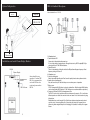
INFRA RED WIRELESS SYSTEM
User’s Guide
IRR-30 / IRR-15 Receiver IRH-15c / IRB-10c / IRN-10 Transmitter
IRD-10/IRD-30/IRD-60 Sensors
Due to constant improvements, specifications are subject to change without a prior notice.
1-12-17 Kamirenjaku Mitaka-shi Tokyo 181-8533 Japan
Tel :+81(0)422-55-5115 Fax :+81(0)422-55-0131
E-mail : [email protected] URL http://www.azden.co.jp
Printed in Japan 080905-2
Index
Specification
IRR-15/IRR-30 Receiver
Page
Subject
2
3
4
5
6
7
8
9
10
11
12
13
13
14
Important Safety Instructions
Handling care for Ni-MH battery
Introduction
Feature
System configuration, Installation case beside Plasma Display Monitor
IRR-30 Receiver set up
IRR-15 Receiver set up
IRB-10c Transmitter
IRN-10 Transmitter
IRH-15c Handheld Microphone
IRD-10/20/60 External Sensor
Trouble shooting
Microphone suggestions, Regulation
Specification
Sub-carrier Frequency
Type
Modulation
S/N Ratio
Reception Sensitivity
Audio Output Adjustment
Audio Output Impedance
Power Requirement
Size
Weight
IRH-15c
Sub-carrier Frequency
Modulation
Microphone Element Type
Battery Type
Battery Life
Size
Weight
Important Safety Instructions
2.06MHz&2.56MHz IRR-15: 1CH IRR-30:2CH
Super Heterodyne-Crystal Controlled
FM
More than 90dB
More than 25dBμV
Mic:-20dB maxLine: 0dB max
Mic:Less than 1.5kΩLine: Less than 1kΩ
12V DC 350mA
100(W) x 161(D) x 44(H)mm (IRR-15)
215(W) x 210(D) x 44(H)mm (IRR-30)
530g (IRR-15)
1.15kg(IRR-30)
2.06MHz&2.56MHz Switchable
FM
Uni Directional Dynamic
2-"AA" Alkaline (1.5V x 2)
2-"AA" rechargable Ni-MH or Ni-Cd(1.2 x 2)
>8hours w/alkaline batteries -low power mode
>5hours w/alkaline batteries -high power mode
240 x 58mm
300g w/alkaline batteries
IRB-10c
1. Read these instructions for use.
2. Keep these instructions in a safe place.
3. Heed all warnings.
4. Follow all instructions.
5. Do not use near water.
6. Clean only with a dry cloth.
7. Do not block any ventilation openings. Install in accordance with the manufacturer's instructions.
8. Do not install near any heat sources such as central heating radiators, electric heaters, stoves,
or other units that produce heat (e.g. amplifiers).
9.Only use attachments/accessories specified by the manufacturer.
10.Use only with the cart, stand, tripod, bracket, or table specified by the manufacturer, or sold with
the unit. When a cart is used, use caution when moving the cart/unit combination to avoid injury
from tip-over.
11.Unplug during lightning storms or when unused for long periods of time.
12.Refer all servicing to qualified service personnel. Servicing is required if the unit has been
damaged in any way, such as mains cable or plug damage, liquid has been spilled, objects have
fallen inside, the unit has been exposed to rain or moisture, does not operate properly or has
been dropped.
Sub-carrier Frequency
Modulation
Microphone Element Type
Frequency Response
Battery Type
Battery Life
Size
Weight
IRN-10
Sub-carrier frequencies
Modulation
Microphone element type
Frequency response
Ext Mic Input Jack
Battery type
Battery life
Size
Weight
IRD-10/30/IRD-60
Output
Power
Size
Weight
2
2.06MHz&2.56MHz Switchable
FM
Electret Condenser
50-10kHz ±3dB
2-"AA" Alkaline (1.5V x 2)
2-"AA" rechargable Ni-MH or Ni-Cd(1.2 x 2)
>10hours w/alkaline batteries -low power mode
>8hours w/alkaline batteries -high power mode
100(H) x 64(W) x 27(D)mm
140g w/alkalaine batteries
2.06MHz or 2.56MHz
FM
Uni-directional electret x 2
50-9kHz ±3dB
3.5mm
2-"AA" Alkaline (1.5V x 2)
2-"AA" rechargeable Ni-MH or Ni-Cd(1.2 x 2)
>10hours w/alkaline batteries- low power mode
>8hours w/alkaline batteries- high power mode
80(H)x70(W)x27(D)mm
120g- Transmitter w/alkaline batteries
62g Transmitter w/o alkaline batteries
F-Connector(IRD-30/60) / RCA-Connector(IRD-10)
Powered by reciever (24V 10mA)
52(W)x27(H)x73(D)mm (IRD-10)
72.5(W)×27(H)×50(D)mm (IRD-30)
100×30mm (IRD-60)
210g Included 10m cable and bracket(IRD-10)
90g Included mounting bracket (IRD-30)
170g Include mounting bracket (IRD-60)
15
Microphone Suggestions
Maintenance and Care
In addition to the attached uni-directional microphone, any one of many fine external microphones
can be used. In the case of head or collar worn mics is that it would be possible to increase the
gain (volume) without adding feedback noise. This is due to the proximity of the mic element to the
speaker's mouth. Any of the following Azden microphones will produce excellent results.
・EX-503 Omni-directional Lavalier ・EX-505U Uni-directional Lavalier
・HS-12 Behind head version of HS-11 HS-11 Uni-directional Headset ・HS-9 Omni-directional Headset
・CM-20D Uni-directional Collar-worn
Do not attempt to service this unit yourself as opening or removing covers may expose dangerous
voltage or otherhazards. Refer all servicing to qualified service personnel.
Clean only with a dry cloth. Do not use detergents or other liquids.
Replacement parts
When replacement parts are required, be sure the service technician uses replacement parts
specified by the manufacturer or those that have the same characteristics as the original part.
Unauthorized substitutions may result in fire, electric shock, or other hazards.
Safety check
Upon completion of any service or repairs to this unit, ask the service technician to perform safety
checks to determine that the product is in proper operating condition.
Regulation
CE Declaration of Conformity
This equipment is in compliance with the essential requirements and other
relevant provisions of Directives 89/336/EC or 73/23/EC.
Before putting the equipment into operation, please observe the respective
country-specific regulations!
FCC Rules
This equipment has been tested and found to comply with the limits for of the FCC Rules. These
limits are designed to provide reasonable protection against harmful interference in a residential
installation. This equipment generates, uses and can radiate radio frequency energy and, if not
installed and used in accordance with the instructions, may cause harmful interference to radio
communications.
However, there is no guarantee that interference will not occur in a particular installation. If this
equipment does cause harmful interference to radio or television reception, which can be
determined by turning the equipment off and on, the user is encouraged to try to correct the
interference by one or more of the following measures:
1) Reorient or relocate the receiving antenna.
2) Increase the separation between the equipment and receiver.
3) Connect the equipment into an outlet on a circuit different from that to which the receiver is
connected.
4) Consult the dealer or an experienced radio/TV technician for help. The users manual or
instruction manual for an intentional or unintentional radiator shall caution the user that changes
or modifications not expressly
14
Handling Care for Ni-MH battery
1 To prevent the battery break, carefully ready this manual.
2 The operation environment of battery is −20℃∼+60℃. If the operation temperature is out of this
range, the battery may damage.
3 Don't leave the battery inside of car under direct sunshine, don't face the battery for direct sunshine
and don't keep the battery beside heater. Also, don't use the batter at very cold place, which is zero
degree or less than zero.
Such environment may make short life and damage goods.
4 Don't put the battery in the slot water and watery.
5 Inside of battery, it includes the alkaline liquid. If the liquid touches to hands, skin etc., immediately
washes them.
Prohibition:
Don't throw away the battery in the fire and don't make warm it.
Don't soldering it directly.
Minus and plus terminal, don't connect by needle, cable etc
Don't set the battery + - terminal in reverse.
Don't disassemble and assembly.
Don't throw away and put high pressure on it.
Recharging user only our accepted recharge.
Don't insert battery into car external battery socket, wall socket.
Don't user any other equipment without our permission.
3
Charger
Introduction
Thank you for selecting the Azden "RED" infrared system as your wireless solution. We are confident that it will
perform beyond your expectations. For over 40 years Azden Corporation has been creating technologically
advanced products. By taking advantage of the latest in CAD design and SMT production techniques, Azden's
engineers are able to produce products that exceed the published specifications and perform well beyond the
warranty period.
Azden "RED" represents a breakthrough in wireless. Instead of the normal radio waves that other wireless
systems use, Azden "RED" uses invisible light beams in the infrared range.
Through the use of infrared you will no longer be plagued by outside interference. "RED's" enhanced
performance assures you of the finest in audio clarity and reliability. The specially selected high-frequencies
provide you with trouble free performance, even in fluorescently lit rooms. Like all infrared, Azden "RED" will
not operate correctly outside in the sunlight.
In the real world, the ability to use multiple systems in the same location without frequency interference will
prove to be a tremendous benefit to you. Using infrared means that the audio generated in your room stays
in your room. Your discussions cannot be overheard on other systems in other rooms.
Designed by professionals - for professionals, Azden "RED" will provide you with years of worry-free,
high-quality performance.
About AC/DC adapter
Use Azden recommending AC/DC adapter for recharging
the battery on the transmitter unit.
BC-27 for IRR-15 / IRR-30
BC-29 for IRB-10c / IRN-10 / IRH-15c
Troubleshooting
The single most important thing to ALWAYS check when trouble arises is the battery.
Make sure they are fresh and the POWER LED is glowing brightly.
SYMPTOM CAUSE
No POWER LED
a. Receiver switch Is set to "OFF"- change to "ON"
b. External 12V DC power source is not connected or is malfunctioning
c. Dead or very weak battery in body-pack or handheld
No audio from body-pack
a. Make sure the volume on the receiver is turned up for the appropriate channel and the bodypack is powered ON
b. If two body-packs are being used, make sure they are set to different frequency channels
c. If using an external mic, make sure it is plugged in to the body-pack properly and the internal
gain control has been adjusted.
No audio from handheld mic
a. Make sure the volume on the receiver is turned up for the appropriate channel and the handheld
mic is powered ON
b. If two handheld mics are being used, make sure they are set to different frequency channels
Intermittent audio
a. Make sure there is a clear path between the emitter and the receiving sensor. Best results are
obtained when the receiving sensors are mounted high - above everyone• fs head Limited
working range a. Install extra external sensors
b. If using a body-pack, set the Power Mode to Hi.
c. Make sure all emitting points on the transmitters are covered by hands, towel etc.
Move them and face the emitting point to the receiver direction.
d. Make sure all emitting points on the transmitters are wet. Make clean with dry towel.
e. Make sure direct sun light or any strong light is coming into the sensor.
Be careful the mounting position of external sensor or the facing direction of internal sensor.
4
13
The IRD-10/30/60 External Sensor
Feature
To increase the working range of the system, up to three external sensors can beadded. External
sensors are powered by the receiver and can be plugged into the "EXT.SENSOR INPUTS" (9) on
the rear panel. Plugging into inputs 1 and/or 2 (9) adds to the built-in front sensor (3) and extends
the working range by 15m with IRD-10, 15m in straight direction with IRD-30 and 15m halfdiameter range in 360 degree.
Plugging into input 3 (9) automatically disconnects the front panel sensor. Thisway, if the front
panel sensor is blocked (perhaps in a secured cabinet or closet) it canbe replaced.
Receiver
◆ New circuit design for minimizing the interference with the Plasma display.
Guide for sensor installation
IRD-10
Fix the installing bracket
by screws firmly.
◆ Internal sensor can cover an open area up to 144 square meter under transmitter high power mode and
108 square meter with Lo mode.
◆ Up to max. three external sensors can be extended depends on size of room. Three type sensors are
available as option item.
◆ Azden Newly designed state-of-the-art Crystal Servo technology for frequency-stable transmitting
Attached screws for wood wall
Vending point
Holes for screwing
1, The black color side should face the near side when fixing the bracket.
Vend the bracket 90 degree to front.
2, Fix screws
Screw pitch: 30mm and 24mm Black color side
3, Slide the sensor unit for hooking up to the bracket.
Adjusting the angle of the bracket for sliding the sensor much easily.
Bracket
IRD-10 sensor
Wall
Emitter
◆ New method for eliminating the strident noise.
◆ Don't get interference by other generally used wireless method like UHF and VHF. At the same location,
even adjacent rooms, same package can be used without any interference.
Sensor
◆ One is IRD-10 ,which can fly to 10m distance on the line of sight. IRD-30, which can cover up / down and
right / left side 120 degree up to 15m in straight direction, and IRD-60 called "Dome sensor" can cover 360
degree area reception up to 15m half-diameter.
Microphone/Transmitter
◆ Three type of microphones, handheld, pendant and table top, are available depends on users' needs.
◆ Handheld microphone IRH-15c utilize two emitters at bottom and top for transmitting audio in all around 360
degree direction. Up to 20m distance in line of sight can fly constantly.
◆ High and low switch for selection of emitting power depends on the size of location and for extending the
life of battery.
◆ Two channel setting on IRH-15c,IRB-10c and IRN-10 can be switched to either channel on the spot by just
sliding switch.
◆ IRB-10c allow speakers for hands free action thanks to pendant or body clip wearing. Use IRN-10 if the
speakers are installed on the ceiling by adjusting the mic gain.
The microphone emitter and sensor top surface face vertically is best position. Adjust the angle for suitable angle.
IRD-30/IRD-60 Installation
IRD-60 Sensor covering area
IRD-30 Sensor covering area:
Up and down direction and both side, each120 degree
15m is covering
distance in frontside
Covering 120 degree
30m is covering
distance in frontside
360 degree
Connection cable is not attached as standard items. Buy coaxial cable 3C-2V or 5C-2V.
12
5
System Configuration
IRH-15c Handheld Microphone
IRD-30
Amplifier
Infrared handheld mic.: IRH-15c
IRR-30 2CH
Transmitter
Installation case beside Plasma Display Monitor
IRR-30
Plasma Display
>1.5m away between sensor
and PDP
IRD-10 Sensor
Table
6
Sensor should be away
more than 1.5m from PDP.
IRD-10 is recommended to
use beside PDP since the
receipt angle narrow than
IRD-30.
1, Microphone head
2, Power Indication LED
Green color is indicated when the power is on.
If it is red color, battery charging requires. Charge the batteries by AC/DC adapter(BC-29) or
replacing with fresh 2-"AA" Alkarine batteries.
3, Power On switch
The mic. start working by sliding the switch to the ON position with proper frequency. About
frequency setting refer clause 8.
4, Microphone case
5, Infra red emitting point
Audio is transmitted from this point. Don't cover this point by hands and any other materials.
6, Another Infra red emitting point
Also, don't cover this part. Hold the battery cover area when you are in operation.
7, Battery cover
2-"AA" rechargeable NI-MH battery is packed as standard item. Only the original NI-MH battery
can be recharged with AC/DC adapter. 2-"AA" alkaline are our recommendation as dry battery.
8, Frequency Selection (CH1/CH2) and output power Hi/Lo
The IRH-15c can be set to transmit on either one of two preset frequencies. This is so that two
different speakers can talk at the same time in the same room. Select the desired one by using
ball-point pen.
Output power also can be changed Hi/Lo. If the distance between microphone and receiver is
very near, set to Lo for saving battery life. At Lo position, the battery life is approx. 8 hours.
(when using Azden original battery after full charging). At Hi position, the battery life is approx.
6 hours.
11
5. Using the IRB-10c:
After inserting fresh batteries, the IRB-10c can be powered by sliding the ON/OFF Switch (4) to the
ON position. The Power LED will glow when the IRB-10c is powered ON as will the red LED on
the front panel of the IRR-30 which corresponds to the chosen channel. Be sure to slide the Power
Switch to OFF when not in use to preserve battery life. The Power LED on the mic will turn from
green to red to indicate "Low Battery".
IRR-30 Receiver Set up
⑤
I. Receiver Front Panel:
⑦
The emitter (1) must be plugged into the IRB-10c (3) and either attached to the clothing with the clip
(2) or worn around the neck with the lanyard as described in section V. The emitter acts as the
transmitter and, for best results, should be worn in such a way as to have a clear path to the
receiving sensor(s).
The IRB-10c can be attached to the belt or other clothing by way of the metal belt clip. It is suggested
that the body-pack be worn in the front portion of the body to avoid the possibility of damaging it.
6. Attaching and Using the Lanyard with the IRE-10 Emitter:
As described above, the emitter(1) can be attached to clothing using the built-in clip. To attach,
insert the metal clip through the holes (2) on the lanyard's clear plastic slide.
③
②
④
⑥
1. Power Switch - turns the receiver On and Off.
2. Power LED - indicates the power state of the receiver.
3. Receiving Sensors - internal receiving infrared sensors.
4. Channel 1 Volume - adjusts the output volume for Channel 1.
5. Channel 1 Indicator - glows green when connecting Channel 1.
6. Channel 2 Volume - adjusts the output volume for Channel 2.
7. Channel 2 Indicator - glows green when connecting Channel 2.
II. Receiver Rear Panel:
IRN-10 Transmitter
2
①
8
6
4
7
1
⑧
5
3
1. Power switch - turn ON/OFF the transmitter by sliding the switch.
2. Power LED - Glow GREEN when the transmitter is ON.Glow RED when the battery is low.
3. Battery door - When replacing the battery slide it down to open.
4. Extarnal Mic input jack - Plug the ext. mic into the jack, then internal mic will be disabled.
5. Power input - Plug the charger jack into the port.
6. Charge LED - Glow RED when when charging.
7. Channel switch - Slide the switch to select the frequency.
8. Mic gain adjusment point - Use very tiny Philip type screw driver for turning the inside screw.
By turning the screw to the counterclockwise, the gain go up and down.
Find the optimum gain by turning the screw while lessening the speech through a speaker.
If howling appear, this phenomenon can be minimized by adjusting the internal microphone
level through this feature. The best solution to avoid the howling is to use uni-directional
microphone like our HS-11(headset mic),EX-505U (lavalier type) etc.
10
⑨
⑩
⑪
⑫
8. Switched External Sensor Input (F connector) - Plugging an external sensor
in here turns the front panel sensor (3) off.
9. 2-External Sensor Inputs (F connector) - Plugging external sensors in here
extends the receiver’s potential working distance.
10. Input Selector - selects either Mic (-20dB max @ 1.5K ohms) or Line (+4dB max
@ 1k ohms) level for the output jack (10).
11. Output Jack - connects the receiver to a mixer or audio amplifier/speaker combination
(1/4 inch connector). In general, choose “MIC” when attaching to a mixer
input and “LINE” when attaching to an amplifier input.
12. Power Input - plug in AC-DC adapter (BC-27) to power receiver (12VAC-1.6A)
Don’t use other one beside of our recommending.
III. Mounting the Receiver:
As infrared operates "line-of-sight" and can be interrupted by any solid object, it is strongly
suggested that the receiver (or external sensors) be mounted or placed in a location that puts the
receiving sensors above the audience's heads or any other obstacles.
IV. Powering the Receiver:
The IRR-30 is powered by a AC-DC power supply(BC-27) . Before turning the receiver
ON be sure to plug it into an active 110-220VAC wall socket and into the rear of the IRR-30 (12).
DO NOT USE any power supply except the our standard.
7
IRR-15 Receiver Set up
IRB-10c Transmitter
⑦
I. Receiver Front Panel:
③
④
1. Power/Volume control - turn the receiver On and Off,adjust the mic output gain.
2. Power LED - Indicate the power state of the receiver.(RED:Power on,Green:Receiving signal)
3. Receiving Seonsor - internal receiving infrared sensors.
II. Receiver Rear Panel:
1. Batteries for the IRB-10c:
The IRB-10c uses two "AA" batteries for power. They are placed in the battery compartment.
After sliding the battery case door off, carefully place FRESH batteries in the compartment in the
directions shown on the sticker. OBSERVE PROPER POLARITY!
The IRB-10c can use either Alkaline or Ni-MH batteries. In the case of rechargeable batteries, be
sure that they are FULLY CHARGED before use. Battery life depends on the type of battery used.
④ ⑤
⑥
⑦
⑧
4. Mic/Line output - output both mic and line input signal.connects to audio amplifier/mixer aux input.
5. Line input - input line level signal in here
6. Mic output - connects the receiver to audio amplifier/mixer mic input.
7. External sensor input - Plugging an external sensor in here.
8. Plug in AC adapter(BC-27) to power receiver. Don't use other one beside of our recommending.
2. Frequency Selection:
The IRB-10c can be set to transmit on either one of two preset frequencies. This is so that two
different speakers can talk at the same time in the same room. While it does not matter which
frequency is chosen for the body-pack, two transmitters cannot share the same frequency at the
same time. To select the desired frequency (channel) slide the switch (8) as shown on the sticker
on the back of the battery door.
3. Power Mode Selection:
The IRB-10c has two Power Modes - Lo and Hi. These modes can be selected via a switch (7)
inside the battery compartment, and affect two areas related to performance- battery life and area
coverage. If the body-pack is switched to the Hi position (7 - to the right) the range is set to
maximum (approximately 144 square meter(1600 square feet)) while the battery life is reduced to
approximately 10 hours with Alkaline batteries. If, on the other hand, the body-pack is switched to
Lo the operating range is reduced to approximately 108 square meter (1200 square feet) and the
battery life increases to approximately 15 hours with Alkaline batteries. Experimentation is the only
way to know which position is best for your room. We suggest, however, that it always best to use
the Lo position if possible as that provides the most economical use.
4. Adjusting MIC Gain:
The MIC gain (volume) is adjustable to compensate for various microphone element characteristics.
The adjustment (9) is located in the battery compartment and can be adjusted using the provided
tool. While speaking into your microphone, adjust the gain(more gain-clockwise rotation, less gaincounterclockwise rotation) until the desired volume level is achieved. Best results are normally
achieved when the gain control on the IRB-10c body-pack and the volume control on the IRR-30
receiver (4 or 6) are both at their mid-points.
8
9