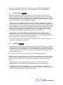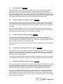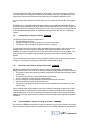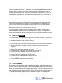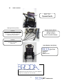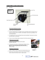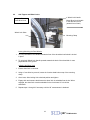
1
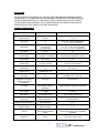
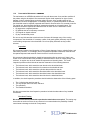
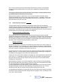
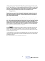
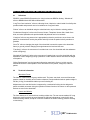
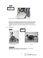
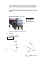
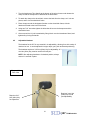
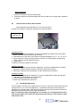
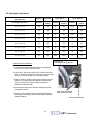
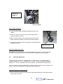
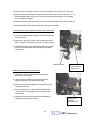
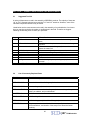
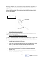
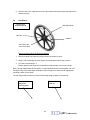
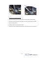
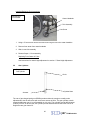
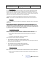
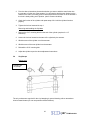
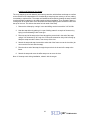
587
Owner, Operator, and Maintenance Manual
Model 587 Manual Wheelchair
560 Bingemans Centre Drive Kitchener, ON Canada N2L 5R8
Can./U.S. Phone: (800)-668-0637
Fax: (519) 746-8616
www.brodaseating.com Email: [email protected]
Register your warranty online at www.brodaseating.com
Last Revised: July 2008
TABLE OF CONTENTS
WARNING ....................................................................................................................................... 3
SPECIFICATIONS........................................................................................................................... 3
GENERAL INSTRUCTIONS ........................................................................................................... 4
SECTION 1 - SAFETY REQUIREMENTS & DETAILED WARNINGS .......................................... 5
1.1
1.2
1.3
1.4
1.5
1.6
1.7
1.8
1.9
1.10
1.11
1.12
1.13
1.14
1.15
Before First Use WARNING ...........................................................6
Application WARNING.....................................................................6
Legal Restrictions WARNING..........................................................7
Position of Wheelchair “Danger of Falling” WARNING ....................7
Position of Seat Tilt “Danger of Tipping” WARNING........................7
Propelling and Transferring “Danger of Tipping” WARNING ...........7
Wheelchair Placement “Danger of Tipping” WARNING...................7
Locking Wheels “Danger of Falling” WARNING ..............................8
Re-Positioning of Patient “Danger of Pinching” WARNING .............8
Accidental Motion “Danger of Falling or Collision” WARNING.........8
Improper Restraint Use “Risk of Serious Injury” WARNING ............9
Improper Use WARNING ................................................................9
Cleaning WARNING ........................................................................9
Preventative Maintenance WARNING...........................................10
Patient Specific Instructions WARNING ........................................11
SECTION 2 - DEFINITIONS AND TECHNICAL INFORMAION- ................................................. 13
2.1
2.2
2.3
2.4
Definitions......................................................................................13
Technical Information ....................................................................13
Shipping and Storage Specifications .............................................14
Label Locations .............................................................................15
SECTION 3 - CAREGIVER MANAGEMENT................................................................................ 16
SECTION 4 - WHEELCHAIR OPERATION ................................................................................. 17
4.1
4.2
4.3
4.4
4.5
4.6
4.7
4.8
Armrests ........................................................................................17
Anti Tippers and Wheel Locks.......................................................18
Seat and Back ...............................................................................19
Accessories…………………………………………………………….20
Headrest........................................................................................21
Solid Seat & Drop Seat and Back..................................................22
Seat Height Adjustment.................................................................22
Seat Depth Adjustment……………………………………………..…24
SECTION 5 - WHEELCHAIR REPAIR AND MAINTENANCE..................................................... 30
5.1
5.2
5.3
5.4
5.5
5.6
Suggested Tool Kit ........................................................................26
List of Commonly Replaced Parts .................................................26
Cables and Cable Handles............................................................27
Rear Wheels and Front Casters ....................................................28
Gas Cylinders ................................................................................30
Vinyl Straps ...................................................................................32
APPENDIX 1 - BRODA WARRANTY........................................................................................... 34
...........................................................................................................................................................
2
587 Tilt Wheelchair
WARNING
DO NOT OPERATE THE BRODA 587 WITHOUT FIRST READING AND UNDERSTANDING
THIS MANUAL. IF FOR ANY REASON THE WARNINGS OR INSTRUCTIONS ARE UNCLEAR,
CONTACT BRODA SEATING AT 1 800 668 0637 FOR CLARIFICATION. DO NOT ATTEMPT
TO USE WHEELCHAIR WITHOUT FULLY UNDERSTANDING THE WHEELCHAIR AND ITS
OPERATION AS IT MAY RESULT IN INJURY OR DAMAGE.
587 SPECIFICATIONS
Item
Standard
Available Options
Weight Capacity
250 lbs
N/A
Seat Depth
17”
15.5” / 18.5” / 20” w/ strapped seat,
16”, 17”, 18” 19” w/ seat pan
Seat Height
15” seat pan
16” strapped seat
14”, 16”, 17”,18”, 19”, 20” seat pan
15”, 17”, 18”, 19”, 20”, 21” strapped seat
Seat Width
16” / 18”
20”
Overall Height
42.5” (upright, w/o headrest)
Varies with seat height/wheel options
Overall Width
26.5” / 28.5”
30.5”
Overall Length
35” (w/o Footrests)
Up to 45.5” (w/ Footrests)
Back Height
24”
26”, 28”, 30”
Degrees of Tilt
Capable of 45° Tilt
Back Angle
90°
Adjustable to 95°, 100°, 105°
Adjustable Arm Heights
(variable, depending on
seat height)
5.5” Range
5/8” Increments
Arm Type
Fixed Height, Swing Up
Detachable
Height Adjustable, Swing Up, Detachable
Front Casters
6” Swivel
8” Swivel
Rear Wheels
22” Mag Rear Mount
20” or 24” Mag Rear Mount
Frame Color
Black Hammertone
Grey Hammertone
Weight (varies with options)
Approx 66-80 lbs
N/A
Shipping Weight
Approx 75-90 lbs
N/A
Footrest
Swing-Away / Adjustable
Length
Elevating Swing Away, Angle Adjustable
Footplates
Strap Color
Black
Grey / Blue / Green / Pink
3
587 Tilt Wheelchair
GENERAL INSTRUCTIONS
The instructions contained herein provide guidance on the safe and correct operation of the
BRODA Model 587 Manual Wheelchair. Safety measures as described in Section 1 must be
observed when operating the wheelchair’s functions or moving the wheelchair.
Every person that is involved with the operation and maintenance of the BRODA wheelchair,
including the patient’s family members, must read this instruction manual prior to moving or
operating the functions of this wheelchair. A copy of this instruction manual must always be
available to these people. No person, including the patient’s family members, who is unfamiliar
with or is unwilling or unable to adhere to the safety and operating instructions contained herein,
should be permitted to operate or move the wheelchair.
The BRODA 587 wheelchair’s intended use is to provide mobility to persons that may be limited
to a sitting position. It is highly recommended that someone such as a nurse, nursing home staff
or family member operate this device to transport patient(s) on even surfaces for safety and
effectiveness. The BRODA Model 587 will be primarily used, but not limited to use, by residents
in Nursing Homes and institutional settings. It is the responsibility of the user, with the help of
his/her qualified healthcare professional, to determine the type of chair required for the individual.
The safety and operating instructions that are included in this manual are very important to the
safe and effective operation of the BRODA wheelchair. Safety requirements that are detailed in
Section 1 must be followed at all times.
BRODA accepts no liability whatsoever for damage or disruptions caused by operating errors,
failure to provide proper maintenance, or the disregard of the instructions contained in this
manual. This also includes the patient’s specific instructions.
BRODA reserves the right to make changes to the specifications of the dimensions, functions,
and components of its products. Any diagrams or drawings provided are not necessarily exactly
the same as the delivered products.
Each BRODA wheelchair is provided with a unique, identifying serial number. This serial number
should be maintained on the wheelchair and with your equipment records for future reference to
obtain replacement parts or additional copies of the operating instructions. To understand
BRODA’s serial numbering system refer to Appendix 2 in the back of this manual, or call
customer service at 1-800-668-0637.
4
587 Tilt Wheelchair
SECTION 1 - SAFETY REQUIREMENTS & DETAILED WARNINGS
This section must be read by all operators of the BRODA wheelchair before they attempt to use
the product. It is the caregiver’s primary responsibility to ensure that only people who are familiar
with the information contained in this manual are authorized to operate or move the wheelchair.
Before operating the chair with the patient in the chair, make sure the patient is properly
positioned to maintain patient and caregiver safety, as well as maintaining the maximum stability
of the chair.
Caregivers must be prepared to support the weight of the patient in the chair when tilting and
returning the occupant of the wheelchair to the full upright position. Always make sure to use
proper body mechanics while operating the chair, to avoid injury.
All service and adjustments to the chair should be performed only while the chair is unoccupied.
Only authorized BRODA accessories and parts are to be used on Broda chairs. BRODA is not
responsible for injury or damage due to unauthorized parts, or accessories being applied to the
BRODA chair.
Immediately after service and adjustments, and before use, always ensure all components of the
chair are securely tightened and in proper working order, otherwise damage or injury may occur.
Always determine your safety limits by practicing maneuvers you would perform using the chair,
such as bending, leaning, transferring, and reaching, in the presence of a qualified healthcare
professional.
Always ensure anti-tippers are attached and adjusted to prevent the wheelchair from tipping over.
Do not lean forward out of the wheelchair any further than the length of the armrests. Make sure
the casters are pointing forward when leaning forward. Otherwise, the chair may tip over.
Do not lift the chair by any removable parts. This action may result in damage to the chair, or
injury to the user.
Do not attempt to pick up objects on the floor by leaning forward and reaching down between
your knees. This may cause the chair to tip forward.
Do not lean backward over the chair back when in a tilt position. Doing so may cause the chair to
tip over.
Do not attempt to propel the wheelchair from a tilted position. Otherwise the chair may tip over.
Do not attempt transfers from a tilted position. Otherwise the chair may tip over.
Do not attempt to maneuver or park on slopes greater than 9º. Otherwise the chair may tip over.
Always engage wheel locks before attempting to transfer in or out of the wheelchair. The wheel
locks are not brakes and should not be used to stop a moving chair, as the chair may tip over.
Do not attempt to climb or descend slopes greater than 9°, go over curbs or obstacles, operate
on roads or streets, or use an escalator to move a wheelchair between floors. Doing so may
cause the chair to tip over and cause bodily harm to you, the occupant of the chair, or cause
damage to the chair itself.
5
587 Tilt Wheelchair
Do not use the footplates for transfers. Do not stand on the footplates. When performing
transfers, or getting in or out of the chair, ensure the footplates are in an upright position.
1.1
Before First Use WARNING
BRODA wheelchairs are provided fully assembled and are considered ready to use after
purchaser inspection, functional testing, and when all training requirements have been met by
qualified caregivers after receipt of wheelchair. If the wheelchair does not appear to be in “ready
to use” condition upon receipt, immediately contact your supplier and do not put the wheelchair
into service until after your concerns have been resolved.
This manual must be read thoroughly by the caregiver(s) directly responsible for the patient’s
nursing care before the wheelchair is put into service. This manual must also be read thoroughly
by new caregivers, prior to the first time a new caregiver operates or moves the wheelchair, once
the wheelchair has been put into service. The patient’s family members, who share some of the
responsibility for the patient’s care, are considered a caregiver only after they have read this
manual, received instruction on the wheelchair’s safe use by a professional caregiver, and a
caregiver directly responsible for the patient’s care has given their approval.
The wheelchair must be visually inspected for damage, missing parts, and loose fittings
(fasteners) prior to first use or testing the wheelchair’s functions. Functional testing must be
successfully completed after visual inspection and before first use. These obligations apply both
to the first use of the wheelchair and to all subsequent uses.
An in-service on the operation and safety issues, as described in this manual, must be given to
the patient’s caregivers prior to its first use.
1.2
Application WARNING
The BRODA 587 Manual Wheelchair will be primarily used, but not limited for use by residents in
a Nursing Home or institutional setting. The suitability and application of a BRODA wheelchair is
to be determined by a professional caregiver who is familiar with the seating needs of the patient
using the wheelchair. Any other use of the wheelchair is excluded from possible liability claims,
and may void the warranty.
The 587 is not to be used in the shower. Use in the shower will void the warranty.
BRODA does not recommend that the user of this chair be transported in vehicles while in the
wheelchair and that appropriate seating in vehicles be provided for the user as made available by
the auto industry. BRODA does not recommend or endorse any wheelchair transportation
system.
The wheelchairs are not explosion resistant and may only be used where there are no
inflammable gases or liquids present such as anesthetics or petroleum based cleaners.
The BRODA 587 wheelchairs are designed for use with specific BRODA accessories and
replacement parts. Any use of non-BRODA spare parts or accessories with a BRODA wheelchair
is excluded from possible liability claims and voids warranty.
6
587 Tilt Wheelchair
1.3
Legal Restrictions WARNING
BRODA wheelchairs may only be used as described in this manual and with proper regard for
recognized healthcare and work place safety and accident prevention practices. BRODA
wheelchairs may not be operated or used with non-BRODA replacement parts or accessories,
which could endanger patients, staff, or other third parties. The wheelchair may only be moved or
operated by caregivers or family members who can guarantee its correct operation because they
have read and fully understand this manual and the safety issues discussed herein.
1.4
Position of Wheelchair “Danger of Falling” WARNING
Immediately after a patient is transferred into a wheelchair, we recommend that the wheelchair’s
seat be tilted sufficiently to prevent the patient from sliding or falling forward off the wheelchair.
The amount of seat tilt used should be determined by the patient’s caregiver who is responsible
for seating.
We recommend that the patient’s feet be correctly positioned on the footrests to prevent the
patient from sliding or falling forward off the wheelchair. The amount of elevation used should be
determined by the patient’s caregiver who is responsible for seating.
1.5
Position of Seat Tilt “Danger of Tipping” WARNING
In an attempt to prevent agitated patients from falling out of the wheelchair or tipping the
wheelchair forward, the caregiver may decide to tilt the wheelchair. The amount of seat tilt used
should be determined by the patient’s caregiver who is responsible for seating. Always ensure the
patient is properly positioned in the chair before tilting.
Before operating the seat tilt, carefully read through section 1.9 Repositioning of Patient “Danger
of Pinching.”
1.6
Propelling and Transferring “Danger of Tipping” WARNING
To aid in patient comfort, the caregiver may decide to tilt the wheelchair. We recommend that the
wheelchair not be propelled from a tilted position since the wheelchair is prone to tip backwards.
Transfers to and from the wheelchair should not be performed from a tilted position because the
wheelchair is prone to tip backwards.
The wheelchair should always be in an upright position when propelling and performing transfers.
If the wheelchair should tip while occupied, the anti-tippers will prevent it from falling completely.
1.7
Wheelchair Placement “Danger of Tipping” WARNING
We recommend that when a patient has been moved to their destination, the wheelchair is placed
so the patient cannot reach handrails or other objects, fixed or moveable. This is to prevent the
patient from pulling the wheelchair over or pulling themselves off the seating surface, and to
prevent the patients from pulling moveable objects onto the wheelchair and on themselves.
We recommend that the wheelchair be used in a supervised area to prevent untrained patients,
caregivers, or third parties from unauthorized operation, movement, or unsafe actions such as
sitting, standing or leaning on the reclined back, footrest, or the armrests. Individuals should not
stand on the seat also. These actions, if not prevented, could put the wheelchair at risk of tipping
or may damage the wheelchair.
7
587 Tilt Wheelchair
The seat depth, back height, size and position of the wheels, use of the anti-tippers, as well as
custom dimensions or changes relate directly to the stability of the chair. Any adjustments to the
above items must only be recommended or performed by an individual qualified to do so.
We recommend that a wheelchair only be used on a level surface to minimize the risk of tipping
over.
All BRODA 587’s are equipped with anti-tippers which are removable and adjustable. However,
they should remain attached to the chair and pointed downward at all times. The anti- tippers can
be pointed upward if necessary for traveling over a curb or such, however then must be returned
to the standard downward position for standard traveling and when the chair is in a stationary
position.
1.8
Locking Wheels “Danger of Falling” WARNING
The wheel locks must always be applied when:
• The wheelchair is not in use.
• A patient is being transferred (moved) into or out of the wheelchair.
• The patient in the wheelchair is not being moved by a caregiver.
It is important to note that if the wheel locks are applied while the patient is in the chair, that the
caregiver does not leave the patient unattended, especially those patients who have the
capability or tendency to propel the chair on their own, and/or those who may be agitated. This
could cause harm to the patient if they attempt to propel the chair while the wheel locks are
applied.
Failure to follow these instructions will unnecessarily increase the risk of serious falls by patients,
caregivers, or third parties caused by the wheelchair unintentionally moving.
1.9
Re-Positioning of Patient “Danger of Pinching” WARNING
BRODA wheelchairs offer the benefits of seat tilt, footrest, and adjustable, removable arms.
During the movement of any of these functions, the following safety measures must be observed:
• The patient’s arms must be securely positioned inside the wheelchair frame with their hands
on their body.
• The patient’s feet must be correctly positioned on the footrests.
• All of the wheelchair’s wheel locks have been applied.
• Only one caregiver at a time attempts to operate the wheelchair’s functions.
• Only one wheelchair function is operated at a time.
• The patient’s and caregiver’s body are clear of all pinch points before operating any of the
chair functions
Failure to follow these safety measures can put the patient's or caregiver’s limbs at risk of injury.
Patients who may be unaware of their body position or unable to maintain a safe body position
have the highest risk of injury from pinching and caregivers should be more cautious with these
patients. A second caregiver may be required to ensure the safety of these patients during these
operations.
1.10
Accidental Motion “Danger of Falling or Collision” WARNING
We recommend BRODA wheelchairs for indoor use within a long-term care institution and where
there is insufficient slope to cause the wheelchairs to move unaided. Wheelchairs used where the
8
587 Tilt Wheelchair
surface is uneven or sloped are at risk of unintended movement and could become a serious
danger to the patient, caregiver(s), or a third party. We recommend that BRODA wheelchairs are
located away from stairwells, elevators, and exterior doorways. Placing the patient near
handrails, tables or stationary objects while the wheel locks are in place should be done with
caution and should be supervised. Failure to do so may lead to unnecessary injury due to the
patient grabbing hold of the object and either pulling the object on top of them, or causing the
chair to tip over.
1.11
Improper Restraint Use “Risk of Serious Injury” WARNING
We recommend that alternatives to physical restraints be used with patients while seated in the
wheelchair except under the specific instructions of the patient’s primary caregiver and with
permission of the patient’s family or guardian. Physical restraints have been identified as a
common cause of serious injury to patients while they are seated. We recommend that the
primary caregiver responsible for seating first considers the re-positioning options available in the
wheelchair to reduce the risks of sliding, falling, or self injury.
If a physical restraint is determined to be appropriate to prevent sliding or falling out of the
wheelchair, BRODA supplies both seat belts and thigh belts. In all cases, it is the patient’s
primary caregiver who must take responsibility for the safety of the patient if restraints are used.
1.12
Improper Use WARNING
The improper use of the wheelchair can be dangerous to the patient, caregiver, or a third party
through:
• Unauthorized operation of the wheelchair’s functions.
• Unauthorized movement of the wheelchair.
• Inappropriate use of the wheelchair by a patient who has not been assessed by the caregiver
responsible for their seating.
• Attempted simultaneous operation of multiple wheelchair functions by one or more
caregivers.
• Attempting to move the wheelchair with the wheel lock(s) applied.
• Applying wheel lock(s) while wheelchair is in motion
• Leaving the patient unattended in the wheelchair near other objects.
• Leaving a potentially agitated patient in an unsupervised area.
• Leaving a patient in a wheelchair on a sloping surface.
• Leaving a wheelchair unattended on a sloping surface.
• Leaving wheelchair unattended without setting wheel locks.
• Transferring a patient in or out of the wheelchair without setting wheel locks.
• Using non-BRODA accessories on the wheelchair.
• Using the BRODA wheelchair at temperatures below 0° Celsius (32° Fahrenheit)
1.13
Cleaning WARNING
We recommend the wheelchair be wiped clean with soap and water. A dilute household strength
ammonia or chlorine based cleaner may be used if necessary. BRODA wheelchairs should not be
cleaned with petroleum based cleaners and any petroleum based products that come in contact
with any vinyl surface should be removed as quickly as possible. Petroleum based products make
vinyl brittle and will damage the seating surface. Metal parts should be wiped dry after cleaning.
The spandex seat and back coverings are to be washed in cold water with small amounts of
detergent. Do not wring out. Hang to dry on a hanger covered by a towel.
9
587 Tilt Wheelchair
1.14
Preventative Maintenance WARNING
The maintenance on a BRODA wheelchair will vary with the amount of use and the condition of
the patient using the wheelchair. We recommend regular visual inspection for signs of wear,
damage, loose or missing fittings, and other safety concerns. Also, periodic testing of the
wheelchair’s functions is appropriate. If a breakage, defect, or operational problem is detected,
the wheelchair must be repaired, inspected and tested for function before it is returned to service.
For regular use, the wheelchair should be inspected and tested on a bimonthly basis. The
wheelchair should be inspected and tested as often as each use if the wheelchair is used:
• By aggressive or agitated patients.
• By patients who have involuntary movement.
• On irregular or sloped surfaces.
• By any unauthorized person.
Do not use any lubricants that contain solvents. Solvents will damage many of the moving
components in the wheelchair. If necessary a white, food grade grease (lubricant) may be used
on the sliding components in the wheelchair. Do not use spray lubricants as they contain
solvents.
Inspection
We recommend regular visual inspection of signs of wear, damage, loose or missing fittings, and
other safety concerns. If a breakage, defect, or operational problem is detected, the chair must
be repaired inspected and tested for function before it is returned to service.
We recommend that the wheelchair should be inspected as often as each use, if there is any
reason to be concerned about the possibility of increased wear or loose or missing fittings. At a
minimum, in regular use, the chair should be inspected on a bimonthly basis. The visual
inspection procedure should include at least the observation of the following fasteners:
•
•
•
•
•
•
The bolts and nuts, which attach the rear wheels to the wheelchair base.
The bolts and nuts, which attach the front casters to the wheelchair base.
The bolts and nuts, which attach the cylinders that position the seat tilt
The bolts and nuts, which attach the wheelchair back to the wheelchair seat.
The bolts and nuts, which attach the wheelchair seat to the wheelchair base.
The bolts and nuts, which attach the wheel-locks to the wheelchair base.
In addition, the visual inspection procedure should include the observation of the following parts:
•
•
•
•
The 2 cylinders that position seat tilt.
The vinyl straps used in the seat, and back.
The upholstery.
The handles and cables.
We also recommend the visual inspection procedure include the observation of any installed
accessories.
Functional Testing
We recommend that the wheelchair operation be tested when unoccupied. The testing may
be as often as each use if there is any reason to be concerned about the possibility of above
normal wear or damage to the chair’s components.
10
587 Tilt Wheelchair
If the caregiver performing the functional testing believes that any function is not operating
correctly, the chair should be taken out of service until a satisfactory functional test can be
completed.
The caregiver performing the testing should be aware that the seat tilt operations will be
more difficult when the wheelchair is unoccupied.
When performing repairs or maintenance, do not use any lubricants that contain solvents.
Solvents will damage many of the moving components in the chair. If necessary, a white, food
grade grease lubricant may be used on the sliding components on the wheelchair. Do not use
spray lubricants on any part of the chair.
1.15
Patient Specific Instructions WARNING
The professional caregiver responsible for the patient’s seating shall add such additional
instructions as are necessary for the safety and comfort of the patient using the wheelchair based
on their professional experience and knowledge of the patient’s specific conditions and
requirements. These instructions form a part of the Safety Requirements for using the wheelchair
with that patient and must be made available to all caregivers.
Safety and Handling of Wheelchairs
This manual describes the most common procedures and techniques involved in the safe
handling and maintenance of BRODA chairs. It is important to understand, both conceptually and
physically, the handling of the chair in order to prevent any injury to body, or misuse of the chair.
The information provided here is to be regarded as a general guide and is based on techniques
that have proven to be beneficial and successful by many users.
Stability and Balance
Any activities that require movement in the wheelchair have an effect on the center of gravity of
the chair. Therefore, it is very important not to lean forward out of the chair any further than the
length of the armrests. Also, do not attempt to reach for objects on the floor by moving forward in
your seat, or leaning over between the knees to pick them up.
If you do need to lean forward, ensure that the front casters are pointing forward to maintain the
stability of the chair. You can do this by pushing forward and then reversing it in a straight line. It
is advisable to also engage the wheel locks when leaning forward.
Leaning over the top of the back upholstery will change your center of gravity and may cause the
chair to tip over. It is advisable to position the chair as close as possible to the desired object,
then point the front casters forward. Reach back only as far as your arm will extend without
changing your sitting position.
When attempting a transfer in or out of the wheelchair, reduce the distance of the gap between
the chair and the destination of the transfer. Ensure the casters are turned parallel to the object
you are transferring onto, and that the wheel locks are engaged.
It is recommended that you practice bending, reaching and transferring activities with the help of
a qualified healthcare professional before attempting such activities on your own. This will
familiarize yourself and your caregiver with the particular safety limits of the chair.
It is important that if assistance is required with the use of the chair, that the caregiver remember
to bend their knees, and keep their back straight whenever tipping the chair, or pushing the chair
over curbs or other obstacles.
11
587 Tilt Wheelchair
Lifting the chair by any removable or detachable parts may result in injury to the user, and will
cause damage to the chair. Check for any signs of loose fittings periodically to ensure parts are
secure. If parts are not secure, contact a qualified technician to assess, and fix, the chair before
further use. Using the detachable parts to move the chair or as lift supports is unadvisable, as
they may be inadvertently released causing possible injury or damage to the chair.
Tipping the Chair
Never tip the wheelchair without assistance. When tipping the chair, the assistant should
grasp the back of the chair on a non-removable part, informing the occupant of the chair as to
what is about to happen and to lean back. It is important that the patient’s feet and hands are
clear of all pinch points and wheels.
For curbs, short stairs and other small obstacles, place your foot on the crossbar of the frame
base and begin to tilt the wheelchair toward you. Push down in a continuous motion until a
balance point is reached and until the front casters clear the obstacle. When lowering the chair,
do not let the wheelchair drop the last few inches as this could cause an injury, or damage to the
chair. Roll the wheelchair forward and slowly lower the front of the chair in a smooth, continuous
motion. Push the wheelchair forward until the rear wheels roll up and over the obstacle. The
assistant may be required to slightly lift the chair to help get the rear wheels over the obstruction.
If the anti tippers are repositioned upward during this operation, be sure to return them to their
proper downward setting immediately after this operation.
Stairways
BRODA does not recommend that the occupant be seated in the chair when moving the chair
between floors when no elevator is available. If there is no other option, two assistants are
required. With one assistant behind the chair, tilt the chair back to the balance point and back
the chair up against the first step.
A second assistant, with a firm grasp on a non-detachable part of the frame, should lift the chair
up and over the stair, steadying the chair as the first assistant places one foot on the next step
and repeats the process.
Never use an escalator to move a wheelchair between floors.
12
587 Tilt Wheelchair
SECTION 2 - DEFINITIONS AND TECHNICAL INFORMAION2.1
Definitions
“BRODA” means BRODA Enterprises Inc. doing business as BRODA Seating. “Wheelchair”
refers to BRODA Model 587 Manual Wheelchair.
“Long-Term Care Institution” refers to a Nursing Home, Hospital, or other Health Care facility that
provides health and personal care to its residents on a long-term basis.
“Patient” refers to an individual using the wheelchair who may be limited to a sitting position.
“Professional Caregiver” refers to the Doctors, Nurses, Therapists, Nurses Aids, Health Care
Aids, and other Specialists who provide health and personal care to its residents.
“Caregiver” refers to any person who is appropriately trained to provide care or services to the
patient or the wheelchair used by the patient and may include the patient’s family members or
guardian.
“Seat Tilt” refers to changing the angle of the wheelchair’s seat with respect to the wheelchair
frame (or ground), without changing the angle between the back and the seat.
“Transfer(s)” refers to the movement of a resident into or out of a wheelchair with the assistance
of their caregiver(s).
“Mechanical Transfer(s)” refers to the movement of a patient into or out of a wheelchair with the
assistance of their caregiver(s) using a patient lift or other assistive device that bears the weight
of the patient.
“Safety Requirements” are the important information contained in Section 1 which must be
followed to ensure the safe operation of the wheelchair for the patient, caregivers, and third
parties.
2.2
Technical Information
Wheelchair Frame
The frame is constructed of 16 gauge tubular steel. The base, seat, back, arms and footrest are
powder–coated for durability and corrosion resistance. Recommended maximum patient weight is
250 lbs (114 kg) for wheelchair widths up to and including 20”.
Adjustments to the seat tilt function is supported by a mechanical locking device designed to
permit controlled movement during the operation of these functions. No motors or other powered
devices are used in the wheelchair.
Casters and Wheels
The front casters are 6” swivel with non-marking rubber tires. The rear mount standard 22” mag
wheels are used for patients to propel themselves. Minimal maintenance is required for both
casters and mag wheels, except for in extreme conditions as steam cleaning, pressure washing
or autoclaving.
13
587 Tilt Wheelchair
Side Panels
Removable side panels provide lateral support and containment of the patient while sitting in the
wheelchair.
Disinfection
For normal cleaning we recommend the wheelchair be wiped clean with soap and water. When
necessary, a household strength diluted ammonia or chlorine based cleaner may be used.
BRODA chairs should not be cleaned with petroleum base cleaners. Any petroleum based
products that come in contact with any vinyl surface should be removed as quickly as possible.
Such products will make the vinyl brittle and will damage the seating surface and cushions. Metal
parts and cushions should be wiped dry after cleaning. Seat and back covers are to be washed in
cold water with small amounts of detergent. Do not wring out. Hang to dry on a hanger covered
by a towel.
2.3
Shipping and Storage Specifications
BRODA wheelchairs should be shipped and stored in an upright condition and not stacked higher
than 3 boxes. No other materials should be shipped or stored on top of a BRODA box. BRODA
boxes should not be placed on pallets.
BRODA wheelchairs should be shipped and stored at temperatures between minus 20 degrees
Celsius and plus 40 degrees Celsius. BRODA wheelchairs should not be used until they are
between 0 degrees Celsius and 30 degrees Celsius. BRODA wheelchairs should be kept in a
clean, dry environment.
On receipt, we recommend that the shipping carton be immediately examined for damage. Any
damage should be noted on the delivery receipt and a request for inspection by the transportation
company should be made. The shipping carton should be opened immediately and the
wheelchair examined for concealed shipping damage. If the wheelchair appears to be damaged,
contact the customer service department at BRODA Seating.
14
587 Tilt Wheelchair
2.4
Label Locations
SEAT TILT
Squeeze Handle
Warning Stickers (Yellow)
Weight Capacity Sticker
WARNING
WEIGHT CAPACITY
250 LBS. (114 kgs.)
REFER TO OWNER’S MANUAL
Propel only from a fully upright seated position
Do not lean over edge of the wheelchair
Operate only on level surfaces
WARNING
DO NOT OPERATE WITHOUT
THE ANTI –TIP TUBES
INSTALLED
Serial Number Label (Silver)
SEATING
1-800-668-0637
PRODUCT #
SERIAL #
MADE IN CANADA
MADE IN CANADA / FABRIQUE AU CANADA
560 Bingemans Centre Drive Kitchener, ON. Canada, N@B 3X9
PHONE 1-519-746-8080 FAX 1-519-746-8616
15
587 Tilt Wheelchair
SECTION 3 - CAREGIVER MANAGEMENT
BRODA’s unique and innovative wheelchairs provide the optimum in re-positioning functions and
mobility. However, BRODA’s products were designed to be recommended by professional
caregivers. The maximum benefit to the patient using this wheelchair will be achieved with the
advice and assistance of their caregivers.
At the customer’s request, the initial basic training of the patient’s caregiver(s) will be provided by
either the local BRODA representative who supplies the wheelchair or the HME Provider. The
caregiver(s) must adhere to the Safety Requirements at all times to ensure the safety of the
patient, caregivers, and third parties.
The customer will maintain a list of caregivers who have read this manual and are authorized by
them to operate and move the wheelchair.
WARNING: BRODA assumes no liability for damage, injury or accidents caused by careless,
negligent, incorrect, or unauthorized operation or movement of its wheelchairs. It is the
responsibility of the caregiver to ensure the patient is secure in the chair and that the proper
degree of care is given based on the patients needs.
16
587 Tilt Wheelchair
SECTION 4 - WHEELCHAIR OPERATION
4.1
Armrests
Arm Top
Diagram #4
Adjustable
Arm Rests
Front Frame Insert
Back Frame Insert
Arm Release
Buttons
Arm Height Adjustment
Pin
Removing & Installing the Armrests
1. Press in front Arm Release Button.
2. Once Arm Release button is engaged, remove Front Frame Insert by swinging arm up.
Once Front Frame Insert is removed, removed Back Frame Insert by pressing in rear
Arm Release Button.
3. To reinstall, push in rear Arm Release Button and insert Back Frame Insert into frame
just behind the rear mag wheel.
4. Push in front Arm Release Button and insert Front Frame Insert into frame
Adjusting the Armrest Height
1. Depress the Arm Height Adjustment Pin toward
the front of the chair
2. Pull up on the arm top to your desired height. Release the pin
and push down until the pin locks with the tube holes.
Note: Do not place fingers directly under arm as this can
cause pinching.
Replacing the Armrest Tops
1. Using a Phillips screwdriver loosen the 2 screws under arm top.
Depressing
Arm Pin
2. Remove Arm Top and place new Arm Top on frame and using
same screwdriver and screw new Arm Tops in place.
17
587 Tilt Wheelchair
4.2
Anti-Tippers and Wheel Locks
Wheel Lock Handle
Diagram #5
Rear Wheel Lock
Move Wheel Lock Handle
in this direction to lock
(toward front of chair)
Wheel Lock Shoe
Mounting Clamp
Locking/Unlocking the Rear Wheels
1. To lock push Wheel Lock Handle towards the front of the wheelchair until wheel is locked
in place.
2. To unlock pull Wheel Lock Handle upwards towards the back of the wheelchair. It rests
perpendicular to the ground.
Adjusting the Wheel Lock
1. Ensure wheel lock is unlocked.
2. Using a 5 mm Allen key wrench, loosen the 2 socket head bolts on top of the mounting
clamp.
3. Once loose, slide Locking Unit to desired position and tighten.
4. Engage lock and measure the distance the wheel lock is embedded into the tire. When
engaged, the wheel lock must be embedded in the tire at least 1/8” to hold the
wheelchair.
5. Repeat steps 1 through 4 if necessary until the 1/8” measurement is obtained.
18
587 Tilt Wheelchair
Anti-Tippers
Diagram #6
Anti-Tippers
Anti-Tipper Wheels
1. All BRODA 587’s are equipped with anti-tippers which are removable and adjustable.
However, they should remain attached to the chair and pointed downward at all times
and adjusted to the longest possible setting. The anti- tippers can be pointed upward if
necessary for traveling over a curb or such, however then must be returned to the
standard downward position for standard traveling and when the chair is in a stationary
position.
4.3
Seat and Back
Tilt Feature
Diagram #7
Tilt Feature
Standard Positioning
Full Tilt 45°
Adjusting Seat Tilt
1. With the patient in the wheelchair, press the tilt handle which is located directly
underneath the right hand grip at back of the wheelchair.
19
587 Tilt Wheelchair
2. Push downward on the hand grips at back of wheelchair while pressing the tilt handle
(patient weight will dictate the amount of assistance that is required). The amount of tilt
used should be determined by the patient’s caregiver who is responsible for seating.
3. Release handle when the desired degree of tilt is obtained.
4. To return the patient to the default seat tilt position, engage the tilt handle and lift up until
seat stops
Adjusting Backrest Angle
1.
Remove bolt on adjustable plate.
2. Reposition backrest angle to 90°, 95°, 100°, 105°.
Diagram #8
Backrest Adjustment
Plate
105°
100°
3.
4.4
95°
90°
Reinstall bolt in appropriate hole on adjustable plate.
Accessories
Installing the IV Pole (Option)
Diagram #9
IV Pole
Attachment Stand
IV Pole
Adjustment Knob
Clamps
IV Support Tube
Attachment Stand Handle
Bolts
20
587 Tilt Wheelchair
1. Turn the Attachment Tube Handle at the bottom of the pole to loosen and release the
clamp so that the clamps can be attached to the base frame.
2. To attach the clamp to the wheelchair, remove the bolts from the clamp, so it is in two
pieces, and fit it to the wheelchair frame.
3. Place clamps around the designated location on the wheelchair frame, with the
Attachment Stand to the back of the frame.
4. Using two 7/16” wrenches tighten the bolts that will secure the clamps around the
wheelchair frame.
5. Once secured, the IV pole is attached by fitting it back over the Attachment Stand, and
tightened by turning the handle.
4.5
Adjustable Headrest
The headrest for the 587 is very versatile in its adjustability, allowing for a wide variety of
needs to be met. It can be adjusted in height, depth, yaw, pitch and lateral positioning.
The headrest requires a 3/16´Hex (Allen) Key for adjustability. A 3
mm Hex (Allen) Key must be used for the ball joint.
NOTE: After adjusting headrest to it’s desired position, always
ensure it is secured in place.
Diagram #10
Rear View
Requires 3 mm Hex
(Allen) Key for ball
joint adjustability
Requires 3/16”
Hex (Allen) Key
for adjustment
21
587 Tilt Wheelchair
Attaching Headrest
1. Insert the vertical post into the mounting tube
2. Place the headrest at the desired height and turn the handle until it is tight and the headrest
is secure.
4.6
Solid Seat Pan and Drop Seat and Back
Broda Seating has developed the 587 V2 to accommodate a wide range of seating. The
587 has the versatility of using other manufacturers’ seats and backs within our chair.
Diagram #15
Solid Seat Pan
Installing Seat Pan
1. Remove strapped seat if applicable. (To Remove strapped seat, detach the four bolts that
attach the seat to the frame and lift seat off frame)
2. Place seat pan on seat frame in the position of desired seat depth of 16”,17”, 18”, 19” or 20”.
3. Secure seat pan to frame by inserting all four bolts each in the appropriate corresponding
holes in the seat pan and attaching to frame.
4. Tighten bolts
To Remove: Reverse Installation instructions
Installing Drop Seat
1. Remove the strapped seat or seat pan if applicable. (To remove strapped seat or seat pan,
Detach the 4 bolts that attach the seat to the frame and lift seat off frame)
2. Place seat in position over the seat frame, as per manufacturers instructions.
Installing Drop Back
1. Remove the strapped back if applicable. (To remove strapped back, detach the bolts that
Attach the back to the frame, and remove back)
2. Place the Back on the frame on the chair.
3. Install as per manufacturers instructions.
4.7
Seat Height Adjustment
The seat height on the 587 can be adjusted from 14” to 20” in one inch increments with the solid
seat pan and 15’ to 21” with the strapped seat. The desired seat height can be achieved by
adjusting the seat height posts, caster and mag wheel sizes and mounting positions. Below is a
diagram that outlines the various seat height combinations:
Note: To achieve the lowest seat height (14” for seat pan, 15” for strapped seat) an extra
hole must be drilled in the caster fork (can be done in the factory or in the field) or a drop
seat must be used.
22
587 Tilt Wheelchair
587 Seat Height Combinations
Seat Height Post Adjustment Range
(With Seat Pan)
Mag Wheel
Mag Wheel
(For Strapped Seat Add 1")
Diameter
Mnt
Position
Diameter
Fork
Position
Diameter
Fork
Position
14", 15", 16", 17"
20"
Mid
6"
High
None
None
15", 16", 17", 18"
20"
High
6"
Mid
8"
High
14", 15", 16", 17"
22"
Low
6"
High
None
None
15", 16", 17", 18"
22"
Mid
6"
Mid
8"
High
16", 17", 18", 19"
22"
High
6"
Low
8"
Mid
15", 16", 17", 18"
24"
Low
6"
Mid
8"
High
16", 17", 18", 19"
24"
Mid
6"
Low
8"
Mid
17", 18", 19", 20"
24"
High
None
None
8"
Low
Caster Option 1
Caster Option 2
Diagram #16
Seat height post adjustment
Seat Height Post Adjustment:
1) Locate the seat height adjustment bolts on both sides of
the front of the seat on the chair frame
2) Using a 3/16” Allen key wrench to the outside of the frame
and a ½” wrench to the inside of the frame, remove the bolts.
Be sure to note the location o the bolts and spacers.
3) Raise or lower the seat by changing the cylinder mounting
position to correspond with the holes at the desired seat
height. (See the seat height combination diagram to
determine the desired seat)
4) Insert the bolts through the desired corresponding holes
and tighten the bolts.
5) Adjust the caster height position and mag wheel position
accordingly if necessary. (See the seat height combination
diagram, page 24)
23
Seat height adjustment
bolts (at front of frame)
Seat height increments
587 Tilt Wheelchair
Diagram #17
Raised seat
height
Raised seat height
Caster Height Adjustment:
1) Locate the three caster fork adjustment positions on the front
casters,
2) Using a ½” wrench, remove the hex screw and locknut that
secure the caster to the fork.
3) Raise or lower the caster to the desired position (See the seat
Height combination diagram to determine the desired position)
4) Insert the hex screw and locknut through the corresponding holes
and tighten the bolts.
Diagram #18
Caster fork positions
Mag Wheel Height Adjustment:
See section 5.4 for instructions on mag wheel installation and removal. See the seat height
combination diagram under section 4.7 to determine the mag wheel mounting position.
4.8
Seat Depth Adjustment
The 587 offers two style seats, a strapped seat or a solid seat pan. The strapped seat is
available in depths of 15.5”, 17” (standard), 18.5” and 20”. The solid seat pan is available in
depths of 16” – 20” (17” standard) in one inch increments. All dimensions are approximate.
Note: For a depth of 20” with a strapped back, a larger seat pan must be used. For depths of 19”
and 20”, with a non strapped back, a larger seat pan must be used
Seat Depth Extension for Strapped Seat
1) Remove the front strap from the seat by cutting the strap and drilling out the rivets that hold it
in place with a 3/16” drill.
24
587 Tilt Wheelchair
2) Remove the two seat plugs from the front of the seat frame (one on each side of the seat).
3) Install the two new seat extension plugs and secure them to the seat frame with the ¼” x 1 ¼”
fasteners applied. Make sure the rivet holes on the seat extension plug are on the outside
when the plugs are installed.
4) Install new straps on seat extension plugs. Refer to strap installation instructions on page 33.
5) Adjust the length of the footrest bracket according to the seat depth.
Footrest Bracket Length Adjustment for Seat Depth Extensions
1) Locate the footrest bracket extension rail bolts on both sides
of the chair frame.
2) Using a 3/16” Allen key wrench to the outside of the frame
and a ½” wrench to the inside of the frame, remove the bolts
3) Adjust the extension rail to the desired position and reinsert
the bolts in the appropriate holes through the seat frame.
Tighten bolts.
Adjustment bolts
Diagram #19
Footrest bracket
extension rail
Seat Depth Extension for Solid Seat Pan
1) Locate the 4 seat pan adjustment bolts that attach
the seat pan to the frame
2) Using a Phillips screwdriver, remove the bolts and
adjust the seat pan to the desired seat depth.
3) Reinsert the bolts in the appropriate corresponding holes
and tighten the bolts
4) For seat depths of 20” or greater with a strapped back,
(19” or 20” with a non strapped back) a larger seat pan
must be used.
5) Adjust the footrest bracket length to accommodate the
seat depth (See instructions above)
25
Diagram #20
Seat pan
adjustment bolt
587 Tilt Wheelchair
SECTION 5 - WHEELCHAIR REPAIR AND MAINTENANCE
5.1
Suggested Tool Kit
A variety of fasteners are used in the assembly of BRODA’s products. The majority of these are
1/4” or 5/16” diameter bolts and nuts requiring 7/16” and 1/2” wrenches. However, some of the
individual component fasteners may be metric.
Listed below are the most common tools used in the assembly of our wheelchairs, from time to
time you may be required to do repairs or modifications in the field. Therefore we suggest
obtaining the following items to make your job easier.
Qty.
2
Item
7/16” combination wrench
Where Used
Nuts & bolts used to secure wheel lock mounting bar to
base
Nuts & bolts used to pivot seat and back, as well as gas
cylinders
Lock nut on the stem of the gas cylinders and nut used to
fasten the caster fork
Bolts on seat height adjustment post and seat rails
Lock nut on mounting clamp of mag wheel
Headrest adjustment
Mag wheel axle
Screws used to secure armrests and cable handles
Use for heating vinyl straps during strap replacement or
reversal
Used for installing of vinyl straps
2
1/2” combination wrench
1
17mm combination wrench
1
1
1
2
1
1
3/16” Allen key
5 mm Allen key
¼” Allen key
5/8” combination wrench
Phillips screwdriver
Heat gun
1
Hand Rivet Gun
5.2
List of Commonly Replaced Parts
Part No.
ACS A-3
Description
Black urethane plastic armrests
PRT-CABHAND
Control cable and handle for gas cylinder release mechanism
PRT-CABLEACT
Actuator for gas cylinder release mechanism
PRT-CABLERELEAS
CASTERS 6”
Complete release mechanism for gas cylinders consisting of the prtcable, prt-cableact, and prt-cablereleas
6 “ front casters
REAR WHEELS
22” Rear Mag Wheels
PRT-PAB7
800N Locking gas cylinder with a 8” long body
PRT-STRAP
Vinyl straps used on wheelchairs. You must specify the color, seat width
of the wheelchair, and location of the strap on the wheelchair when
ordering.
26
587 Tilt Wheelchair
Note: Please include the model number and serial number of the wheelchair whenever you are
ordering parts. These can be found on a sticker that is attached to the cross member on the
bottom of the chair.
NOTE: Only a person with training on the BRODA chair should attempt to do any repairs or
maintenance on the wheelchair. Certain repairs may require a BRODA representative to
personally attend to the repair. If you are unsure as to what is required, call BRODA customer
service at 1-800-668-0637.
5.3
Cables and Cable Handles
Diagram #21
Cable and Handle
Cable Handle
Cable
Maintaining the Cables and Cable Handles
The cables and cable handles do not require any maintenance. Both replacement pieces are
shipped out together fully assembled.
Removing and Installing the Cables and Cable Handles
The cable is used in conjunction with a cable handle and an actuator to control the function of the
gas cylinder. The cable is held in place on the handle end by a cable housing retaining clip. On
the actuator end the cable hooks into the lever that depresses the control pin on the cylinder and
the cable housing clip into the actuator housing.
1. Unclip the cable from the actuator on the cylinder.
2. Cut the cable ties that secure the cable to the frame of the wheelchair (carefully note the
location of the cable ties and how the cable is threaded around the frame of the
wheelchair.)
3. Unscrew the handle from frame using a Phillips screwdriver
4. Remount the new handle assembly to the frame of the wheelchair using the screw
removed in step 3.
5. Feed the new cable around the frame of the wheelchair the same as the previous one
and install new cable ties where necessary.
27
587 Tilt Wheelchair
6. Hook the end of the cable into the lever in the actuator and clip the cable housing into the
actuator housing.
5.4
Rear Wheels
Diagram #20
Rear Mag Wheel
Rear Mag Wheel
Hub Cap
Handrim
Axle (where hex
screw is located)
Removing and Installing the Rear Mag Wheels
1. Remove hubcap from wheel by turning counter clock-wise by hand
2. Using a 5/8” combination wrench, loosen hex screw and locknut at axle of wheel
3. To install, reverse steps 1-2.
Ensure that the head of the bolt is towards the inside and the nut is on the outside
Note: The rear mag wheels can mounted in 3 vertical positions on the mounting plate: low, mid
and high. Refer to the seat height combination chart on page 24 to determine the appropriate
mounting position for the wheel.
The rear mag wheel can also be mounted horizontally along the base on the side rail.
Diagram #21
Mag wheel
mounting plate
Diagram #22
Side rail
28
587 Tilt Wheelchair
Replacing the Rear Wheel Hand Rim
1. Remove rear wheel(s) from wheelchair (see Removing/Installing the Rear Wheels)
2. Remove the mounting screws from the inside of the wheel using a Phillips screwdriver
3. Remove existing hand rim
4. Install new hand rim by reversing above steps
5. Reinstall rear wheel (see Removing/Installing the Rear Wheels section for instructions)
29
587 Tilt Wheelchair
Installing/Replacing Fork Assemblies
Diagram # 21
Front Caster
Caster Headtube
Fork Assembly
Hex Screw
1. Using a 17mm wrench remove the locknut securing the fork to the caster headtube
2. Remove front caster from caster headtube
3. Slide in new fork assembly
4. Reverse Steps 1-3 for reassembly
Replacing Front Caster in Forks
See instructions for caster height adjustment in section 4.7 Seat Height Adjustment
5.5
Gas Cylinders
Diagram #22
Gas Cylinder
Clevis
Cylinder Stem
Actuator
The use of gas charged springs on BRODA products allow the caregiver to easily make
adjustments to the tilt and recline with a minimum amount of effort. The gas cylinders contain
pressurized Nitrogen gas, it is not flammable nor is it toxic. The cylinders provide 800 Newtons
(180 lbs) of force. In other words, the cylinders provide assistance and reduce the amount of
weight the care giver has to lift.
30
587 Tilt Wheelchair
Part No.
Part No. PRT-PAB7
Description
350N locking gas cylinder with a
10” long body
Where Used
Used for the seat tilt
How do they work?
On the end of the stem of the cylinder is a small pin. When the operator depresses the handle
this pulls on the cable which in turn pulls on a small lever inside the actuator mechanism into
which the stem of the cylinder is mounted. This depresses the pin which opens a valve located
inside the barrel of the cylinder, allowing for changes in position. When the operator releases the
handle, the valve closes and locks the cylinder in the desired position.
The function of the actuator is to push against the pin and open the valve that controls the
cylinder. If the actuator is not properly adjusted when mounted on the cylinder, problems will
occur.
Maintenance
The gas cylinders generally do not require any maintenance. Adjustments may be needed due to
cable stretch.
When adjusting the cylinder it is important that you do not damage the stem on the
cylinder. Small scratches left by applying the jaws of pliers or Vice Grips directly to the
shaft while making adjustments will destroy the seal and allow the gas inside the cylinder
to escape. Use a piece of vinyl strapping, cloth or rubber to protect the cylinder shaft from
the jaws of the tool you are using to make the adjustments!
Troubleshooting the Cylinders
Often, when experiencing problems with cylinders on BRODA wheelchairs, the cylinder is not
damaged, it usually only requires an adjustment. There are two common adjustments.
1. The pin that the cable handle pulls on at the end of the cylinder is not connected
correctly.
2. The handle or cable assembly is broken or disconnected.
Other solutions to common problems are listed below.
•
The wheelchair is not tilting when cylinder handle is pulled.
The pin in the end of the cylinder is not being depressed when the handle is pulled. Action to
take: See adjustment steps that follow
•
The wheelchair tilt seems to slowly slide out of position.
The pin in the end of the cylinder may be still partially depressed.
Action to take: See adjustment steps that follow.
Adjusting the Cylinders
Note: Cylinder does not need to be removed from the wheelchair to make this adjustment.
1. Loosen the lock nut located on the stem of the gas cylinder, next to the actuator, with a
17mm wrench.
31
587 Tilt Wheelchair
2. From the above instructions, determine whether you want to wind the stem further into
the actuator or further out of the actuator. You will need to wind the stem further into the
actuator if the chair is not tilting (wind it clockwise) and wind it further out of the actuator if
the chair is slowly sliding out of position. (wind it counter clockwise)
3. Check the function of the cylinder and repeat steps 3 & 4 until the cylinder functions
properly.
4. Tighten the lock nut loosened in step 1.
Removing and Installing the Cylinders
1. Remove the 5/16” mounting bolt from the end of the cylinder (requires 2 x 1/2”
wrenches).
2. Loosen the lock nut located on the stem of the cylinder by the actuator.
3. Wind the stem of the cylinder out of the actuator.
4. Wind the stem of the new cylinder into the actuator.
5. Reinstall the 5/16” mounting bolt.
6. Adjust the cylinder as per the above adjustment instructions.
5.6
Vinyl Straps
Maintenance
Diagram #23
Vinyl Strap
The only maintenance required for the vinyl strapping is general cleaning with an ammonia or
chlorine based cleaner (Do not use petroleum based cleaners).
32
587 Tilt Wheelchair
Installing and Replacing Vinyl Straps
The vinyl strapping has both elasticity and memory retention, which allows each strap to conform
to the resident as an independent unit. Occasionally a strap may lose memory or be cut, making
it necessary to replace them. The straps are installed under tension by heating the strap so that it
is soft and pliable, enabling it to be easily stretched during installation. They are held in place by
riveting them to the steel frame of the wheelchair and then wrapping them around the frame over
the top of the rivet. This is done the same for both ends of the strap.
1. Remove the old strap by cutting it in two and drilling out the rivets with a 3/16” drill bit.
2. Heat the strap either by placing it in a pot of boiling water for a couple of minutes or by
laying it out and heating it with a heat gun.
3. Rivet one end of the strap to the frame through the precut hole in the end of the strap,
using a 3/16” diameter by 3/8” long rivet. Ensure the crowned or shiny side is facing up.
Wrap the strap around the frame, over the top of the rivet.
4. Stretch the strap and wrap it around the other side of the frame next to the rivet hole (do
not cover the rivet hole with the strap).
5. Rivet the other end of the strap, through the precut hole in the end of the strap to the
frame.
6. Stretch the strap and move the offset strap over to cover the rivet.
Note: If the strap cools during installation, reheat it with a heat gun.
33
587 Tilt Wheelchair
APPENDIX 1 - BRODA WARRANTY
Register your warranty online at www.brodaseating.com
BRODA Seating April 2008
GENERAL INFORMATION
WARRANTY
BRODA provides a Life Time Warranty on the wheelchair frame and cross braces, and a One Year Warranty
on all other components subject to the following conditions:
No warranty is provided on seat pads or cloth covers.
The wheelchair frames and cross braces are guaranteed for the life of the chair against structural defects or
failure. All other parts (except seat pads and cloth covers) including but not limited to strapping, cushions,
gas springs and attachments, casters, wheels, brakes and armrests are guaranteed for one year against
defects in materials and workmanship based on normal institutional use. The guarantee does not cover
malicious or deliberate damage or damage from misuse.
Modifications to BRODA products or the use of non-BRODA supplied parts voids the warranty. This
warranty does not cover shipping damage (see below).
BRODA will provide new or refurbished parts for installation by the owner at no cost following confirmation
by the local BRODA Representative or the BRODA Head Office Customer Service Representative. On
request, defective parts must be returned to the factory within thirty days of receipt of the replacement parts
by the owner. If the defective parts are not returned to BRODA on request, the owner will bear the cost of
the replacement parts on invoice from BRODA.
Warranty does not include on-site labor for the installation of warranty parts or warranty repairs. The owner
may return to BRODA products for warranty replacement or repair by shipping items prepaid and insured to
the factory. Warranty completed at the factory includes both materials and labor. Parts to be repaired or
replaced at the discretion of BRODA. All returns to the factory require prior authorization from BRODA.
BRODA retains the right to make design and application changes without notice. All orders will be filled with
BRODA's current models unless otherwise specified by the purchaser.
BRODA wheelchairs are designed for patient mobility, positioning, and comfort in specialty seating,
however, the application of BRODA products shall remain the responsibility of the purchaser or user.
This warranty is not transferable.
RETURNS
BRODA Seating will not accept any returns without a prior Returned Goods Authorization Number. Please
contact our Head Office Customer Service Representative at 1-800-668-0637 for assistance. Returns must
be insured when shipped.
DAMAGED FREIGHT
NOTIFY THE CARRIER OF ANY DAMAGE IMMEDIATELY
It is the responsibility of the person receiving the goods to examine cartons and goods before accepting
receipt. Note all damages on the bill of lading and file a claim if necessary. Notify the carrier of any
concealed damaged within a maximum of 48 hours.
BRODA insures all products for in transit damage, failure to notify the carrier of in transit damage voids both
the insurance and the BRODA warranty. If you require assistance, please contact our Head Office at 1-800668-0637
SALES TAX
Most BRODA products are G.S.T. Zero Rated and Exempt from Canadian Provincial Sales Tax. Purchasers
maybe required to check with their Provincial or State Tax Office for purchaser tax payment.
34
587 Tilt Wheelchair