1
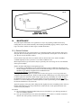
ENDEAVOUR 40 OWNERS MANUAL
ENDEAVOUR 40 OWNERS MANUAL
Table of Contents
1.
Introduction
2.
List of Figures
3.
Construction
3.1 Hull
3.2 Deck
3.3 Deck/Hull Joint
3.4 Rudder and Steering
3.5 Ballast
3.6 Interior Construction
4.
Spars and Rigging
4.1 Spars
4.2 Standing Rigging, Running Rigging, Chainplates
4.3 Static Tuning (at the Dock)
4.4 Dynamic Tuning (under Sail)
5.
Fuel System
5.1 Fuel Tank
5.2 Fueling
6.
Engine and Transmission of Power
6.1 Engine
6.2 Transmissions
6.3 Propeller Shaft and Stuffing Box
6.4 Shaft Alignment
6.5 Propellers
6.6 Removal of Propellers
6.7 Installation of Propellers
6.8 Propeller Alignment
6.9 Exhaust System
7.
Engine Controls
7.1 Description
7.2 Starting the Engine
7.3 Stopping the Engine
8.
Electrical System
8.1
8.2
8.3
8.4
8.5
8.6
8.7
General
Direct Current (D.C.) System
Battery Maintenance
Alternating Current (A.C.) System
A.C. Shore Power
A.C. Ship’s Power (Auxiliary Generator)
Generator Diesel
2
9.
Plumbing System
9.1 Head and Holding Tank
9.2 Galley Stove Operation
10. Maintenance
10.1 Gelcoat Surfaces
10.2 Ports and Hatches
10.3 Teak
10.4 Hull Bottom
10.5 Standing Rigging
10.6 Running Rigging
10.7 Lifelines, Pulpits, Stanchions
10.8 Winches and Block
10.9 Engine
10.10 Power Train
10.11 Electrical Maintenance
10.12 Upholstery
10.13 Steering
11. Fitting Out
11.1 Prior to Launching
11.2 After Launching
11.3 Stepping the Spar
12. Laying Up for Winter Storage
12.1 Hauling (Slings)
12.2 Cradle Support
12.3 After Haul Out
12.4 Fresh Water. System
12.5 Head and Holding Tank
12.6 Batteries
2.
LIST OF FIGURES
Figure Title
Page
1
1A
1B
2
3
4
5
6
7
8
9
10
11
12
13
4
4
5
6
8
15
15
16
16
17
21
not avail.
not avail.
not avail.
12
Deck-to-Hull Joint
Topside Deck Layout
Interior Deck Layout
Chainplate Installation
Reefing System
Deck Wiring
Head System Description
Plumbing System Description
LPG System
Alcohol Stove System
Lift Strap Locations
AC/DC Electrical Panel Wiring Diagram (no generator)
DC Panel Wiring Diagram (generator option)
AC Panel Wiring Diagram (generator option)
Cockpit Instrument Panel Wiring
3
3.
CONSTRUCTION
3.1) Hull:
The hull is molded as a single unit of a combination of polyester resin and fiberglass woven roving and
multi-directional chopped strand fiber (MCSF). The keel is molded integrally with the hull and all
ballast is contained inside. The exterior finish is a pigmented gelcoat molded onto the fiberglass. The
boot and sheer stripe are also gelcoat molded permanently into the hull.
3.2) Deck:
The deck and cockpit, like the hull, are molded as a single unit of a combination of polyester resin and
fiberglass woven roving and MCSF. Plywood coring is incorporated between layers of fiberglass in the
cabin top, deck, seat, and cockpit sole areas to give additional stiffness. The non-skid finish is molded
into the deck. All exterior deck surfaces are a pigmented gelcoat molded onto the fiberglass.
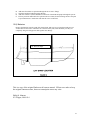
3.3) Deck/Hull Joint:
The joint between the hull and deck is one of the
most important assembly steps in the construction of
a yacht. The method used by Endeavour Yacht is
simple, strong, and reliable. Figure #1 illustrates
details of this assembly.
During assembly, the top of the integral hull flange is
liberally coated with a combination adhesive/sealant.
The deck is then lowered onto the hull and fastened
in place with stainless steel bolts. When the bolts are
tightened, the excess compound is forced into all
crevices and out the sides. The teak cap is then
installed, bedded in a heavy layer of the same
compound and secured in place, doubly ensuring
water tightness.
3.4) Rudder and Steering:
The rudder is molded as a single piece of solid high
density foam with a protective skin of fiberglass and
a gelcoat finish. The foam material is of high
strength structural grade and has exceptional
toughness. The rudder post, molded integrally inside
4
rudder, is solid stainless steel, which is welded to a steel blade in the interior of the rudder.
Where the rudder post passes through the hull, water tightness is ensured by means of a stuffing box. It
is recommended that the packing inside the stuffing box be replaced annually to ensure continued
water tightness. Packing of the proper size is available from most marine hardware stores. The
Endeavour 40 requires 3/8” square packing. Cut packing in individual rings rather than a long spiral to
prevent binding on the rotating shaft.
The pedestal steering system installed on your yacht operates with stainless steel cables rotating a
quadrant bolted and keyed to the rudder post. The cables run through a conduit attached to a massive
steel support frame at the rudder and the motor mount then to the pedestal where they are shackled to a
stainless steel chain running over a sprocket on the steering sheel shaft. Normal maintenance should
only require occasional oiling of all the moving parts with teflon grease, inspection of cables for wear
and proper tension, and a check of all bolted connections for tightness.
3.5) Ballast:
All ballast is internally mounted inside the keel, which is molded integrally with the hull. Cast pieces
of lead are placed in the hull, encapsulated in a polyester bonding resin, and then covered with a layer
of woven roving to form a fiberglass cap. When finished, the ballast becomes a structural part of the
hull.
3.6) Interior Construction:
The interior of your Endeavour 40 is built up of wood. First, a framework of floor timbers is
constructed and placed in the bilge and heavily bonded in place with woven roving. A plywood sole is
glued and screwed on top of these floor timbers and bonded to the hull all around its periphery with
woven roving.
All timbers and plywood are saturated with polyester resin before assembly to seal all exposed wood.
Next, the entire sole is covered with teak parquet flooring, bonded in place with a waterproof adhesive.
All bulkheads are bonded to the hull with two layers of woven roving on both sides.
5
4.
SPARS AND RIGGING
4.1) Spars:
All spars (masts, booms, and spreaders) are extruded aluminum 6061-T6 alloy with a protective
coating on all external surfaces. The main mast of the E-43 is stepped through the cabin roof onto the
keel. The mizzen mast is stepped on deck with a supporting post or structure immediately under the
mast.
4.2) Standing Rigging, Running Rigging, Chainplates:
Standing rigging refers to all the fixed pieces of
stainless steel wire which support the mast. If
they principally support the spar in a fore and
aft direction, they are called “stays” (backstay,
forestay, etc.). If they support mainly from side
to side, they are called “shrouds” (upper
shroud, etc.).
The forestay attaches to the stem head fitting at
the bow. This is fabricated of welded stainless
steel and through bolted to the hull with backup plates. All other stays and shrouds are
attached to chainplates at the edge of the deck.
These chainplates are stainless steel straps
through bolted to the hull. Additional fiberglass
reinforcement is molded into the hull in all
chainplate areas. See Figure #2 for a
description of this installation.
All standing rigging is attached to chainplates
with adjustable turnbuckles that allow fine
tuning of rigging tension.
Running rigging includes all working lines or
cables that normally require adjustment when
sailing. Examples of these include halyards,
sheets, reefing gear, outhauls, etc.
All halyards are stainless steel wire rope spliced
to dacron line tails to minimize stretch, reduce
windage aloft, and maximize service life. All
halyards are run externally to the mast to
facilitate inspection, repair, or replacement.
4.3) Static Tuning (At the Dock)
First, make certain that the mast is centered on the boat, straight up and down when viewed from the
bow or stern. To make certain the mast is plumb transversely, slacken the lower shrouds fully by
undoing their turnbuckles. Make sure the mast wedges are removed from the main mast, which is
stepped through the deck. Take the main halyard and lead the shackle end to a point at the deck edge
so the shackle just touches the chainplate or rail with a given tension. Tie off the halyard. Take the
halyard to the same location on the other side and with the same tension the shackle should just touch
the rail or chainplate. If not, let off one upper shroud’s turnbuckle and take up on the other to bring the
masthead closer to centerline until the halyard shackle touches both points under the same tension. The
6
particular part of the rail or deck you choose as your reference point is not important as long as it is the
same point on each side After the mast is centered transversely, tighten both upper shroud turnbuckles
uniformly, one full turn on one side, then one full turn of the other. Repeat until the turnbuckles
become difficult to turn. Pin the turnbuckles Tighten up the lower shroud turnbuckle so that almost all
of the slack is removed. That is, the shroud itself should be able to flop about 1” in each direction.
Sight up the trailing edge of the spar to make sure that it is still straight. Now, check your rake. With
the main halyard hanging plumb behind the mast, the shackle end should be about one mast width
away from the back face of the mast, near the gooseneck. It’s best to do this on a calm day and to hang
a weight on the halyard such as a hammer, wrench, or bucket of water.
Ease off the forestay or backstay as required and tighten the other to adjust the rake. Large adjustments
may also necessitate tightening and loosening of the forward and aft lower shrouds. Once proper rake
is established, further adjustment should not be necessary of either the forestay or backstay. Tighten
the turn-buckles to obtain proper tension and pin.
Reinstall the mast wedges and trim collar on the main mast.
Check that the spreaders are angled upward slightly to equalize the angles above and below between
the spreader and the shroud. Tape and pad the spreader ends to avoid wear and tear on sails.
4.4) Dynamic Tuning (Under Sail)
Select a pleasant day with a steady 8 to 12 knots of breeze. Put the boat on a starboard tack, close
hauled Sight up the luff groove of the spar. If the mast seems to fall off to leeward at the spreaders, luff
up slightly and tighten the starboard lower shrouds a couple of turns. Put the boat back on the wind and
check the spar again. When the mast appears straight, put the boat about and do the same on the port
side. Check the following carefully. First, if the upper shrouds are at optimum tension, then the
leeward rigging should begin to look slack when at about l50 -200 of heel. This is quite natural and the
leeward shrouds should never be tightened. Secondly, when close hauled under genoa and main, the
forestay will appear quite sagged. Tensioning the backstay will reduce the amount of sag, but the sag
itself can never be completely eliminated.
The forward lower shrouds should be tightened marginally more than the aft lowers to encourage a bit
of a forward bow to the mast. This forward bow is counteracted by the luff of the mainsail and the aft
lowers. Aft bow of the mast should not be allowed, it destroys the sail shape and is countered only by
the forward lower shrouds. If you find that the mast tends to bow aft rather than forward under
backstay tension, the problem may then lie in your mast step. For example, if the mast is resting on its
forward end, it may tend to bow aft. Therefore, to correct this situation, wedge up the after part of the
heel to encourage a forward bow.
If yours is a brand new boat, chainplates may seat and the rigging may stretch to the extent that tuning
from scratch will be necessary in a matter of weeks. This is expected and typical of any new boat.
However, after this initial working-in period, you will find that your boat tends to hold this tune for
fairly long periods of time. After becoming used to the feel of the boat, you may wish to either increase
or decrease the amount of “weather helm” - that is, the amount of feel on the wheel. Any sailboat when
going upwind should have a tendency to “round up” slightly or head into the wind if you let go of the
helm. However, if you’re constantly fighting the boat in order to hold her off the wind, you have too
much weather helm. This can be alleviated by taking some rake out of the spar; i.e., raking the spar
further forward, and thus moving the center of effort of the sailplan further forward. If you find when
sailing upwind that the boat tends to fall off the wind and you are constantly having to push her to
weather, then you probably have lee helm. This can be overcome by putting a bit more rake into the
spar.
With constant tuning as the season progresses, your boat performance will improve. The boat will feel
more comfortable to sail. You will find that tuning is a bit of an art; you’ll begin to notice subtle
changes in the behaviour and response of your boat as you make subtle changes in tuning. The
important thing to remember is to go about things in a slow and orderly fashion, and before you make
any change, make sure it makes sense in your own mind.
7
RIGGING SPECIFICATIONS All lengths pin to pin
ENDEAVOUR- 40 MAIN
RIG
HEADSTAY
BACKSTAY
UPPER SHROUDS
LOWER FWD SHROUDS
LOWER AFT SHROUDS
SLOOP
LENGTH
51’ 6”
53’ 9½”
49’ 9½”
26’ 2½”
26’ 4”
DIAMETER
3/8”
3/8”
5/16”
5/16”
5/16”
4.5) Reefing:
A) How to Setup Boom
1.
A deadend for the reef line must be
installed (unless 3550 boom is being
used and then you can tie the reef
line around the boom in proper location). This will vary in location
depending on the cut of the sail and
the reef location in the sail.
2. To determine the location of the
deadend, lower the mainsail at the
dock to the reef position. Place tack
reef cringle on reef hook provided at
gooseneck. Stretch sail tight by
pulling on the clew reef cringle
towards the outhaul. Mark position
of clew reef cringle on boom when
sail is tight. From this mark, measure
4” towards outhaul and mark on
boom. At this point, install an eyestrap (Kenyon SM-225-2) using (2)
10-24 x ~“ round head machine
screws. An alternative deadend can
also be a grommet installed by your
sailmaker in the foot tape of the
mainsail in the same location as
described for the eyestrap.
3. Use similar method to locate second
reef deadend point.
• SEE FIGURE #3 B) Rigging the Reef Line
1.
Take reef line from outhaul casting up through clew reef cringle and back down to the
eyestrap on boom (tie bowline in eyestrap).
Alternative method: Take reef line from outhaul through clew reef cringle back down and
around boom. Pass end line through grommet in foot tape of main and tie figure eight knot or
timber hitch.
2.
Use similar method to rig second reef line (use available second outside sheave in outhaul
casting).
8
3.
If you have a third reef point, rig an endless messenger between the second and third cringles
with a short end loose as shown. After you have put in the second reef, untie the now unused
first reefing line, tie it to the messenger and pull it through the third cringle and tie to the
appropriate eyes trap (or through the grommet in the foot of the sail if you prefer this method)
and you are ready to set the third reef.
• SEE FIGURE #3 C) Reefing Procedure
1.
2.
3.
4.
5.
6.
7.
5.
Ease boom yang and mainsheet - make sure topping lift is secured in position.
Lower main halyard so that tack reef cringle can be placed on gooseneck reef hook. Retension
main halyard when hooked in place.
Clew reef line must now be tensioned so that clew reef cringle is brought down snugly against
boom.
Readjust mainsheet and boom yang.
Use similar method for second reef.
The reefed folds of cloth can be rolled up and secured with short lines through the reef points
and around the folds and boom. Be sure to untie these first when preparing to shake out the
reef.
UNREEFING: Just reverse this process to Unreel mainsail.
FUEL SYSTEM
5.1) Fuel Tank:
Your fuel tank is built of welded marine grade aluminum with internal baffles.
The fuel tank is positioned in the keel cavity under the main cabin sole. Removable panels in the sole
provide complete access to all fittings, gauges, and removable inspection plate.
All 40 foot model fuel tanks have additional pick up and return fittings for an optional auxiliary
generator. If no generator is installed at the factory, these are plugged with removable caps for possible
future use.
5.2) Fueling:
Before opening the deck-mounted fuel inlet cap, be sure all open flames are extinguished, no person is
smoking, plus that all electrical circuits and the main switch are turned “off”. The fuel nozzle must
contact the metal deck plate to ground static electricity.
The fuel tank vent is located on the hull side immediately adjacent to the deck fill plate. When you
hear a burbling sound from the air escaping through the vent, your tank is full. Wash off any spilled
fuel on the deck or hull side with fresh water.
It is good practice to always keep your tank full when the boat is to be idle for extended periods. This
will prevent condensation forming in the air cavity above the fuel in a partially full tank and possibly
contaminating the fuel with water. In some cases, the denser water settling to the tank bottom could
adversely effect engine performance.
6.
ENGINE AND TRANSMISSION OF POWER
6.1) Engine:
All Endeavour models are equipped with inboard diesel engines.
All necessary data and information is contained in the Engine Owner’s Manual and is not repeated
here. Read this manual carefully. Get to know your engine well and give it proper maintenance to have
9
years of economical, dependable service. Specific technical questions regarding your engine may be
answered by your dealer.
6.2) Transmissions:
The diesel of the 40-foot model is fitted with a mechanical drive. To ensure trouble-free operation of
the clutch, only use oil of the recommended type. Under no circumstances should the oil contain any
additives such as molybdenum sulphite. We recommend commercial Automatic Transmission Fluid
(AFT), Type A.
Check the oil level in the gearbox about once a month. Correct oil level: index mark on dipstick.
Always use the same oil grade when topping up. Change the oil for the first time after about 25 hours
of operation, the; at intervals of at least 1 year.
6.3) Propeller Shaft and Stuffing Box:
All models have solid stainless steel propeller shafts. The diameter of the E-40 shaft is 1¼”.
The propeller shaft is supported at the inboard, or engine end, by the shaft coupling. A square key is
used to prevent turning of the shaft in the coupling. In addition, a stainless steel bolt with locking nut
passes through the coupling and shaft to prevent backing out of the shaft in reverse.
The shaft passes through the hull at the stuffing box. Water tightness is ensured by the packing
material in the stuffing box. A slight dripping, say three or four drops per minute, under power is
normal and desirable. Always tighten the packing nut (farthest forward) by hand, never with a wrench.
The locking nut (aft) can be wrench tightened against the packing nut to lock the system in position. It
is important to never over tighten this stuffing box as excessive twisting loads will be placed on the
rubber hose between the stuffing box and shaft log. In extreme cases where the stuffing box would be
virtually locked to the shaft by over tightening, the rubber hose could be ripped apart allowing sea
water to enter.
The packing material should be changed annually to ensure trouble-free service. Packing of the proper
size is available from most marine hardware stores. The E-40 takes 3/16” square packing. Cut packing
in three or four individual rings, rather than a long spiral, to prevent binding on the rotating shaft.
The prop shaft on the E-40 foot model is supported at the aft end by a cutlass bearing mounted in a
stainless steel shaft log bolted to a fiberglass skeg immediately aft of the keel. The skeg is integrally
molded with the hull.
All cutlass bearings can be removed for replacement by loosening the allen head set screws and either
driving the bearing out from one end or, in difficult cases, sawing it into three lengthwise sections with
a hacksaw blade and prying them out. The replacement bearing should be a light drive fit. Light
hammer taps should be sufficient to drive in place. Sand or lathe turn the outside of a replacement
bearing to obtain the proper fit. Replace the alien screws when in place.
6.4) Shaft Alignment:
All new Endeavour yachts are shipped with the shaft coupling disconnected to ensure that alignment is
performed after delivery. All molded fiberglass boats will change shape slightly when launched,
causing the relationship between the engine and propeller shaft to change. It is essential to align the
shaft coupling only after launching, especially with new boats.
Alignment is checked in the following manner:
A) Remove the bolts on the shaft coupling.
B) Slide the couplings together by hand.
C) Use a feeler gage or paper-thin metal sheet to check that the gage is gripped with equal friction
completely around the circumference of the coupling faces.
D) If the feeler gage does not pull evenly around the entire coupling, the engine is misaligned. This is
corrected by adjusting the mounts on all four corners of the engine.
10
E) Once even spacing is measured all around the flange, rotate the shaft 1800. If a significant
mismatch occurs, your shaft is bent and must be straightened or the coupling face is out of square
with the shaft centerline and must be machined to correct.
F) Replace bolts and evenly tighten.
6.5) Propellers:
The standard propeller supplied with all Endeavour models is a solid bronze, two-bladed type. It has a
tapered bore that mates to a tapered shaft end and is held in place with two locking nuts and a cotter
pin. A square key locks the propeller to the shaft preventing any rotational slippage of the prop.
The hydraulic transmission on the diesel engine in the E-40 foot model cannot be locked and the
propeller will free wheel at any gear shift position. According to the engine manufacturer, this will not
cause damage but the slight noise from the rotating shaft may be an annoyance to you. A commercially
available prop shaft lock can be fitted to correct this and is highly recommended if long range cruising
is anticipated.
The standard propeller size is 17x17 R.H. two blade; the optional propeller size is l7xl6 R.H. three
blade.
6.6) Removal of Propellers:
A wheel puller or prop puller is required. This is available from automotive or marine hardware
dealers.
To remove a propeller, proceed as follows:
A) Remove the cotter pin and shaft nut.
B) Leave the propeller retaining nut in place but installed about one or two turns loose from the tight
position (to protect the threads). The puller shaft should bear directly on the end of the propeller
shaft or on the propeller retaining nut. If it bears on the propeller retaining nut, a spacer of brass,
aluminum, or copper should be used to protect the nut. The puller must be installed straight and
centered carefully so that its maximum effectiveness can be realized. Place the claws of the wheel puller behind
the propeller hub.
While pulling the hub, it is often a help if the propeller hub is tapped with a composition hammer. If
the propeller has been on for some period of time, some effort may be required to remove it.
6.7) Installation of Propellers:
Ensure that the bore of the propeller is free from and corrosion and that the end of the shaft is clean.
The keyways of the propeller and shaft must be free from burrs. Place the propeller on the shaft with
the keyways in the shaft and propeller in line. The key should fit as snugly at the sides with a .01”
minimum clearance at the top. Do not force the key in as this may cause the propeller to be forced off
center. The propeller, the locking nut, and the cotter pin are then assembled on the shaft. Check to
ensure that the propeller is correctly aligned.
6.8) Propeller Alignment:
Install the propeller completely as to be used.
Clamp a piece of thin metal or wood on the propeller strut
or skeg to touch one blade edge of the propeller. Rotate the shaft and the propeller by hand. Any
variance in the track will be indicated by either a gap between the next blade or the blade striking the
indicator. If the propeller is so indicated to be out of line, it should be checked and balanced by a yacht
marine yard familiar with this type of work.
11
6.9) Exhaust System:
In the Perkins engine, a water pump draws water through the intake port, circulates it through a heat
exchanger, where it is pumped in the muffler and overboard through the exhaust port. The salt water in
the heat exchanger lowers the temperature of the engine coolant circulated through the engine block by
means of the normal engine water pump. This coolant is 50% ethylene glycol (anti-freeze) and 50%
fresh water and protects the system to approximately -340F
The ethylene glycol should be used at all times to help prevent corrosion in the engine.
7.
ENGINE CONTROLS
7 .1) Description:
The engine controls for your boat consist of throttle and gear shift levers mounted on the starboard and
port side of the steering pedestal, respectively. The instrument panel is located in the inside port
cockpit coaming.
The instrument panel on the 40 consists of a combination keyed ignition switch and start switch, a
toggle switch for panel lights, a momentary push button for engine stop, gauges for amperage, cooling
water temperature and oil pressure, an audio/visual warning device that lights and sounds for low oil
pressure or high water temperature, plus an electric tachometer for engine RPM.
The 40’s blower is activated from the master electrical panel below. It is recommended that your
blower be operated continuously during engine operation to circulate fresh air to the engine. it is not
necessary, however, to run the blower prior to starting as diesel fuel vapors do not pose an explosion
hazard.
12
7.2) Starting the Engine:
•
1) Turn the battery selector switch on the main electric panel to position ““, “, or “both”, depending
on battery condition.
2) Switch engine room blower on.
3) Check that engine water intake valve is open and that water strainer is unobstructed.
4) Check fuel level.
5) Check that gear shift lever is in neutral and that throttle is slightly open. (With a Perkins engine, a
cut off switch is incorporated to prevent starting if the engine is in gear.)
6) Turn ignition key on. Audio and visual alarms will activate and provide a check on their operation.
7) Turn key or push start button to start engine.
8) Check lights or gauges for any problems. Audio/visual alarm should turn off after start. Check
exhaust port for proper water circulation. If oil pressure is not indicated or water is not being
circulated and discharged from exhaust, shut down immediately and check engine systems.
9) Repeat prior checks about ten minutes after start. If they do not indicate normal operation, shut
down and check engine systems.
10) Always shift gears only with the throttle closed to a slow engine idle.
11) When running under power, frequently check your gauges to monitor engine operation. Check
your fuel level to ensure adequate reserves to prevent running dry, necessitating a complete engine
bleed of the fuel system upon refill.
NOTE During cranking, sea water enters the lift or can-type muffler from pump. This may cause muffler to
overfill and permit water to back-up into engine when cranking is stopped. Therefore, when starting
engine, do not crank for longer than a total of 30 seconds (at 10-second intervals). It may be necessary
to drain muffler if longer cranking is required. Check engine for cause of failure to start if draining
muffler is necessary.
7.3) Stopping the Engine:
1) Close the throttle to a slow idle and place the gear shift in neutral. On the Perkins powered 40,
push the stop button on the cockpit instrument panel. Turn of f the ignition switch when engine is
stopped. It will not harm your electrical system to turn off the ignition switch and remove the key
while running, but your start button/switch will then be inoperative.
2) If the engine is not to be used again for long periods, the water intake valve may be closed but this
is normally not necessary. If severe freezing temperatures are anticipated, drain your raw water
cooling system to protect the engine.
3) Turn off engine room blower. If finished with other power in the yacht, turn the main battery
switch to “off”. NEVER turn off the battery selector switch while the engine is running or you will
permanently damage the engine alternator. One may switch battery selector positions from one to
another while running, but not to “off”.
8.
ELECTRICAL SYSTEM
8.1) General:
The electrical system in your Endeavour yacht has been designed to ensure as much trouble-free
operation as possible. Wiring and connections are kept as high in the interior of the yacht as practical
to reduce exposure to water. Virtually all wiring and connections are accessible by removing panels
from under the side decks.
All ship’s wiring is plastic coated 10 gauge stranded copper with crimp type connectors used at all
junctions or terminals. All D-C wiring is two wire, color-coded: red (positive) and yellow (negative).
Battery cables are:
red (positive) and black (negative). All A-C wiring is three-wire, color-coded: black (hot), white (A-C
common), and green (ship’s ground).
13
Metallic fittings (through hulls, etc.) below the water line are electrically bonded together with green
plastic coated 8 gauge copper wire and connected to a common ship’s ground. This is done to
minimize the effect of electrolytic action when the boat is used in salt water.
8.2) Direct Current (D.C.) System:
The D.C. system in your yacht is powered by two 12-volt batteries connected in parallel to allow single
or combined use. All shipboard D.C. equipment runs from these batteries. The batteries are charged
from the engine alternator only when the engine is running.
The main electrical panel has a battery selector switch that allows use of either battery, or both, and
serves as the master D.C. on/off switch. A battery condition meter with a momentary toggle switch is
also provided to monitor battery condition.
NEVER turn the battery selector switch to “off” while the engine is running or serious permanent
damage will be done to the engine alternator.
Combination on/off and circuit breaker switches are displayed on the main electrical panel for various
shipboard D.C. equipment. The amperage protection of each switch will vary depending on the service
provided.
8.3) Battery Maintenance:
Frequently check the fluid level in your batteries to ensure optimum performance. Add water as
required. Keep the terminals tight and coat them with Vaseline or equivalent to prevent corrosion and
undue electrical resistance.
When charging your batteries with an auxiliary battery charger, first remove all the caps and
disconnect the positive (red) cable.
Hydrogen gas will bubble out of each cell during charging. Hydrogen gas is lighter than air so it will
dissipate, but it is highly explosive so do not smoke or create sparks near the battery when charging.
Provide adequate ventilation during charging.
8.4) Alternating Current (A.C.) System:
The A.C. system in your yacht operates on 115-volt, 60-cycle alternating current. Power is supplied
from a 30-ampere shore service by connecting a cord to the receptacle in the coaming side.
8.5) A.C. Shore Power:
Shipboard A.C. equipment can be operated at dockside by connecting your shore power service cord
from the dock outlet to the receptacle on the coaming side. Make sure the master on/off switch on the
electrical panel is in the “of f” position before connecting to shore power.
•
IMPORTANT IMMEDIATELY after connecting to shore power, check the polarity indicator light on your panel
to ensure that your dockside power source is properly wired. If you cannot indicate proper
polarity, IMMEDIATELY DISCONNECT THE SHORE I’OWER CORD and determine the
source of the problem as serious electrical shock hazards may exist to persons on board or
alongside your yacht, EVEN IF THE MASTER A-C BREAKER SWITCH IS TURNED OFF.
Once proper polarity is indicated, turning on your master A.C. switch will now supply A.C. power to
the other A.C. switches on the panel. The master switch is also a circuit breaker limiting the supply to
30 amperes.
All A.C. equipment can now be operated by turning on the individual A.C. switches. Each switch is
also a circuit breaker with individual maximum current limitations
14
On yachts equipped with hot water heaters, always make sure the heater is full of water before turning
it on to prevent permanent damage to the heating coils. One can be sure it is full by operating the hot
water tap on the pressure water system and observing continuous water flow.
9.
PLUMBING SYSTEM
9.1) Head and Holding Tank:
Proper operation and maintenance procedures for
your head are covered in the information
provided by the head manufacturer. It is
important to understand and use your head
properly to ensure trouble-free operation.
Government regulations require all U.S. yacht
manufacturers to install a holding tank system or
approved waste treatment system to prevent
water pollution. All Endeavour yachts are
provided with plastic holding tanks with deck
pump out fittings for this purpose. However, a
direct overboard head discharge bypass is
provided for use in waters where discharge
regulations do not apply. Figure #5 describes the
head plumbing; figure #6 describes the entire
plumbing system.
15
9.2) Galley Oven Range:
The Endeavour 40 is equipped with either an alcohol oven range or a gas oven range. All necessary
data and information is contained in the range manufacturer’s manual and is not repeated here. Figures
#7 and #8 describe the plumbing system for these ranges.
16
10.
MAINTENANCE
All yachts require maintenance on a regular basis to stay in top operating condition and to keep
looking their best. One should constantly check running and standing rigging, winches, engine, head,
bilge, and surface finishes for telltale signs of needed maintenance.
10.1) Gelcoat Surfaces:
The best protection for your gelcoat surfaces is to clean them regularly with fresh water and a good
detergent. Wax all smooth gelcoat surfaces with a good automotive or boat paste wax at least twice a
year. Do not wax non-skid deck surfaces.
Gelcoat surfaces may stain if leaves or debris collect on deck or birds roost. Surfaces should be
scrubbed frequently or have a protective cover if these conditions occur.
Minor imperfections in gel coat surfaces may be repaired by the owner using one of several methods.
Some typical examples:
Shallow Scratches and Dings (not through the gel coat)
• If a scratch is not through the gel coat into the fiberglass, it may be sanded out with 320 grit wet
and dry sandpaper used with water. Finish off with 400 and 600 grit with water and hand buff with
automotive-type rubbing compound. Wax for additional luster.
Deep Scratches and Flaws (exposed fiberglass) - Thoroughly clean the damaged area with acetone to remove dirt, grease, or wax. Tape off the area
around the flaw with masking tape. Thicken a small amount of matching gel coat with talcum powder
to obtain a putty-like consistency. When ready to apply the putty, thoroughly mix a small amount of
the hardener into the gel putty. A table spoon quantity of gel putty will require only one drop of the
hardener to cure into a hard plastic in mild temperatures. Some experimenting will allow you to adjust
the amount of hardener to suit your needs.
Apply the gel putty with a putty knife, filling the flaw slightly above the surrounding surface. Allow to
harden. Sand and buff as previously mentioned for small scratches. Clean up hands and tools with
acetone before putty hardens.
CAUTION:
A) The clear hardener should be handled with great care. Flush skin or eyes with large amounts of
water if accidentally splashed.
B) Once gel coat materials have been mixed with hardener, never return to a container of unmixed
material. The entire quantity would cure into a solid mass.
17
C) Be careful of discarding uncured, mixed gel coat material. Once hardener is added, a chemical
reaction takes place that generates heat. Large quantities can become very hot. Submerge material
in water until cured for maximum safety.
Flaws in Textured Non-Skid Surfaces - - Chip away any loose material and clean area to be repaired
with acetone to remove any trace of dirt or wax.
Make a thick gel putty as described in instructions for deep scratches and add hardener. Apply to
surface with a stiff bristled brush dabbing gel putty in place. With experimentation and practice, a
texture similar to the non-skid pattern can be created. A good quality artist brush for oil paints works
well.
In extreme cases where a fairly large repair is required, say an area 2” in diameter or larger, a piece of
textured vinyl matching the non-skid pattern can be pressed into wet gel putty, applied to the flaw, and
then rolled over to flatten. Coat the vinyl with paste wax before applying to facilitate removal. This
vinyl fabric material is available from Endeavour Yacht on request. When the putty is cured, peel off
the vinyl and blend the edges of the repair with a sharp knife. Minor touch up with gel putty around the
repair edge may also be required to blend the patch.
10.2) Ports and Hatches:
The opening ports on your yacht are molded in lexan and the deck hatches are glazed with plexiglass.
These materials are extremely tough but may require occasional polishing to remove surface scratches.
Clean the surface with soapy water only, never an abrasive cleanser. If polishing is required to remove
scratches, use a plastic polish applied with a soft cloth.
10.3) Teak:
Exterior teak trim will weather to a dull gray appearance if not oiled regularly. Always wash your teak
before oiling to remove dirt and salt. A light pass with bronze wool or fine sandpaper followed by
treatment with a good quality exterior teak oil three or four times a year will keep the wood looking
new.
11.
FITTING OUT
11.1) Prior to Launching:
A) Clean hull surfaces and repair any damage. Wax hull surfaces above waterline. Paint all surfaces
below the waterline with an antifouling paint.
B) Check all thru hull fittings inside and out for proper operation, corrosion, or damage. Repair as
necessary. Close all valves before launching.
C) Replace all water drain plugs in engine and muffler. Check all hoses for tightness and
deterioration. Repair as required. Drain and replenish fresh water cooling system, if so equipped,
with 50/50 antifreeze! water mix.
D) Check propeller shaft, strut, cutlass bearing, and rudder gudgeon for deterioration or damage.
Repair or replace as required.
E) Check steering system for proper operation. Check tension in cables, free play in fittings, and
proper stop adjustment. Lubricate entire system.
F) Check that batteries are fully charged, battery terminals are clean, and all electrical connections
are secure.
G) Examine all deck and cockpit surfaces. Repair any flaws and wax all surfaces except non-skid
areas.
H) Check all deck hardware and fittings and service all winches. Check docklines and ground tackle
for wear or deterioration and repair or replace as required.
18
11.2) After Launching:
A) Check all through hull fittings, gate valves, sea cocks, and the bilge to ensure that leakage is not
occurring.
B) Open the valve for the engine cooling water intake.
C) Turn on main power switch and bilge blower.
D) Use hand primer located at fuel pump to charge the fuel system.
E) Start the engine. After engine has reached operating temperature, shut down and change the oil.
11.3) Stepping the Spar:
Spars are stepped by two methods, depending on a yacht’s design. Some spars are stepped directly on
the deck of the yacht, the imposed load being transferred to the keel by means of a support inside the
yacht. Other spars go through the deck at a mast collar and are seated on a mast step located on top of
the keel. The procedure for stepping the spar basically is the same for both types
The spar first should be laid out on two or more saw horses and checked carefully. Spreaders should
have the pins in place and all standing rigging pinned at the tangs Halyards must run freely and head
sheaves turn easily. Install and cheek running rigging. Examine halyards for wear and replace if
necessary. All lights, plus any mast head wind instruments, should be checked. Main upper shrouds
should be positioned in spreader ends and locked.
Tie all running rigging together and secure tightly to the spar with light line at a point that will be just
above the mast collar when the spar is stepped. Tie the forestay, backstay, and two main shrouds
together in a separate bundle and secure with light line to the spar at a point that will be approximately
three feet above the deck when the spar is stepped.
Remove cotter pins and clevis pins from all turn-buckles and place in a container for future use. Back
of f all. turnbuckles to the maximum. Carefully locate and secure the yacht adjacent to a crane, making
sure the mast step is within the radius of the crane arm. Place the spar on saw horses adjacent to the
crane.
Prepare a rope sling which will take the weight of the spar. A 10 foot line, minimum 5/8” diameter,
tied in a loop will suffice. Place the loop around the spar below the lower spreaders OUTSIDE THE
RUNNING RIGGING. THE FORESTAY, BACKSTAY, AND MAIN SHROUDS MUST BE
OUTSIDE THE SLING. Make fast a ½” tie-down line to the sling, securing the other end to a winch or
cleat at the bottom of the spar. This line prevents the load of the spar being carried by the spreaders
when the spar is raised to a vertical position. It also facilitates pulling down the sling after the spar is
stepped. Attach the lifting hook to the sling. In some instances, the crane height may not be sufficient
or the sling must be positioned below the mid-point of the spar. Additional persons may be necessary
to offset the weight above the sling and guide the spar into position. At least three persons should be
present when stepping the spar in addition to
the crane operator. Position one person at the foot of the spar to take the weight of the foot as it is
raised and to guide the foot toward the yacht. A second person should clear the rigging as the spar is
beside the mast step to guide the foot of the spar into position.
Raise the spar carefully, guiding the foot toward the yacht. Position one person on the yacht; pass the
foot of the spar from shore to this person. Raise the spar to an almost vertical position and guide the
foot into the step located on the deck. All electrical wiring at the bottom of the spar must precede the
spar through the collar. Free the forestay, backstay, and main shrouds, ensuring that all are clear of the
crane lifting cable.
With the weight of the spar on the step, attach the forestay, backstay, and port and starboard main
shrouds. Place the wedges around the spar at the collar to support the spar at this point. Lower the
crane lifting cable sufficiently to allow the sling to be lowered and released, taking care that the sling
and hook do not damage the light on the forward side of the mast.
19
Release lower shrouds from their lashing, connect the lower shrouds and snug up all turnbuckles.
Replace clevis pins and cotter pins. To help prevent damage to sails, insert all clevis pins fore to aft or
outboard to inboard and tape over the cotter pins. Release all running rigging and lead to the
appropriate blocks and winches. Proceed with tuning the spar at the dock. (Section 4.3)
To unstep the spar, reverse the above procedure. Before removing the spar for winter storage, make a
diagram of the location of the running rigging to serve as a guide when the mast is restepped. DO NOT
use masking or filament tape On the spar. It is better to leave a stored spar unwrapped.
12.
LAYING UP FOR WINTER STORAGE
12.1) Hauling (Slings):
The proper placement of lifting slings and supports is most important when hauling out. Improper
placement could cause damage, slippage of straps, or skewed lifting angles. Slings should never be
placed on the propeller shaft or strut. To prevent scratching of topsides or rubrails, it is recommended
that carpet or a protective liner be placed between lifting straps and areas contacted. See Figure #9 for
recommended lifting strap locations.
12.2) Cradle Support:
When hauling on a marine railway or placing the yacht in a winter storage cradle, virtually all of the
yacht’s weight should be on the keel. Pads or chocks for supporting the bottom of the hull should be
firmly wedged or jacked in place. These side pads should not be over tightened or local deformation of
the fiberglass hull could occur. The sole purpose of these pads or chocks is to prevent the yacht from
falling over on its side. They are not intended, nor is it necessary for them, to carry any significant
portion of the yacht’s weight.
12.3) After Haul Out:
A. Scrub down the bottom to remove any marine growth and grease. Wash down top sides and deck.
B. All gear that may be damaged by cold or damp weather, such as clothing, batteries, books, life
jackets, etc., should be removed from the yacht and placed in a warm, dry storage area.
C. Lubricate or cover all exposed mechanical fittings to guard against ice or snow.
D. Check all electrical and mechanical components on boat and remove those needing repair or
replacement during the winter.
E. Winterize and lay up your Diesel engine per instructions in the ~ s manual.
F. Put a wooden plug in, or plastic cover over, the exhaust pipe in stern of boat.
G. Shut off gas tank valve.
H. Remove, clean, and dry fuel pump bowl. Return bowl to its position making sure it is installed
squarely on the gasket. tighten clamp firmly by hand.
12.4) Fresh Water System:
A.
B.
C.
D.
Remove one of the hoses at the lowest point of system and allow it to drain into the bilge.
Pump the bilge, cleaning it at the same time.
Remove the inspection port on the top of the water tank and dry with a cloth.
Place some baking soda in an open glass container and place in the tank and lay the inspection port
back on.
E. Pump sink water pumps to remove any water remaining in them.
12.5) Head and Holding Tank:
A. Pump out holding tank and flush once or twice.
20
B.
C.
D.
E.
Add some Elson Blue or equivalent through the deck ‘waste’ fittings.
Clean the head bowl and pump water through.
Add some antifreeze (such as Methanol) to the bowl of the head and pump it through the system.
For best protection and trouble-free operation the next season, do the following: Remove the parts
as per manufacturer’s instructions and clean all valves on the head.
12.6) Batteries:
Remove the batteries from the yacht, fully charge them, and store in a cool and protected area on a
wooden shelf for the winter. If batteries are to remain in the yacht, make absolutely sure they are
completely charged to help protect them against frost damage.
20’ Between Straps
This is a copy of the original Endeavour 40 owners manual. Efforts were make to keep
the original content accurate, however transcription errors may exist.
Philip N. Johnson
S/V Flipper, Hull #114
21
-."'
i''''
(
PERKINS
~
IA1
ALTERATION
IIlO.
DRAWING
-~,
"I.',
- WAYNIS
I ,',', I,ll
...
-
-
-REMOVE
ALL
& SHARP
BURRS
CORNERS
UNLESS OTHERWISE SPECIFIED.
TOLERANCES TO BE ± 00 30' UNLESS OTHERWISE SPECIFIED.
ANGULAR
M/M
B
ALTERATION,
NO.
ALL FI LLETS AND ROUNDS TO BE 3 [0.12]R
INCH
/
,
TOLERANCES ON MACHINED DIMENSIONS TO ± 0,4 [0.016] UNLESS OTHERWISE SPECIFIED.
II.'
~[;r
:"':'''--''
(
HOLE CENTERS & PITCH CIRCLE DIAMETERS TO BE WITHIN ± 0,2 [O.OOB].
NOT TO BE SCALED
"'1
I
ALL DIMENSIONS IN MM [IN.].
----
-
-
-.
----------
-Il"........./'/-INS,"'R.VfllJ:N"rPAP~L
(R~AI2 v:
cf//)
C
ALTERATION,
NO.
TA,('HOliETER\
I
,/- G'-":0100]
~
---_
.
I0I
ALTERATION
~-
~c
,...,.I_--," __
Q
~
~
~
~
~
'=
rG
o
0\
I' ---I
r-fo
="---_
--L-
-,
b
~I-1'
'~.-9----;:'
::;-2':.'7
'<1'
,)'
FUlL r-"7Ufl1P
STOP 5:XcNYC
:.{.!
c.-.:"Ei.jk.'EK
~R
!.
~I
t.
,s ttle property
ENGINES
INC.
for
m~nufJClu'">~
without
our
autholl,y
uwo:!
purpf)sI!S
ENGINES
).o.-e ,¢)
®i
I: "
1
I'
'/'-8·0791
,'2:EO
:
'I'.~:
.-.-1
,
11;
I'
11ti
-'
I~I
I~I
JI~I
~'_.E_--__
cD)
I
~
!<J
';!
__~__
J
OFTICIIVA,!_
~:
fi
Tf/t/2MO.':;
TLJ/2T
'IVlRIN6
({J:
il
1)1,-_-
JI. ---,
REO
'i-h~II----~_~C-4_C!..:
..
!:e,.::J"";,
(INf?(ICT. 1t7A'./s FRA,4fe Geouw/)
~
i
1
---- --44·e
J!
Ek~
E ~-~S----- +-E--,!
I I:'"
j , i
r: c.,ArK
\..."
--
.-1
.
--
1--·--
-
-,
"l
II
~-
---~
\~
~----l
61
INC.
-c:
~<TC-FC\
I
I BATTERY
in wrol'
,,,,.
e PERKINS
-\~
l;-
i
-I~-'-' -----'\
\~""r
,,.,format'ol'> ,n ccnnecucn wun
COPIed or
'J'
,
---
and
our eocu.rv. Oldel or contract.
to be
2 eJ
~111-j../'
IG,!ICl'R\/1
('I
-+--!
of
,s submitted as c:onh::ltntial
II i~ not
IJNs';'~II"
(9~1
=-
PERKINS
T"ILc i ~ ' l".
I
';RHN
.4,S.
1___
--L-
u
I
<, -,
E ----,
;II~I' I I
I ,TA,TTLE.
ffi
ALTERATl01F'
drawing
,("_-
....,
~-'--
This
.--
~ ~~Ar-1P¥-'!
~ ~ " <:> ~i~l~
i
~
v
i'EH'P saoJDE/?
-1Lf:
~~
~
.o
A[ttRATION
NO.
----
(9
E
ALTERATION,
NO.
_-==r===
..----:-----
I
~
_/
~
:"E':'~ /NjTl::C'UME/v!
,/;\ SEE
W/k-/N~
PA'!,-=-'. v',;/';:>/1;/01/..:100;7-';;
N/~R!VE5':: !P -::-:"574)
~I-
~
PART NO. & MANUF ACTURERS
Q.C.
SURFACE
APPL.
us
lIS
/59/
15/3/"
TEXTURE
SPECIFICATION
ANSI - 846.1
V'MACHINE
TO
FIRST
USED ON: -
INTRODUCTORY
D
-
NONE
SCALE: -
@
MATERIAL:
T~7 w.35d.4
ALT:
THIRDANGLEPROJE:TlON
WIRI;1j6 f)IA,GRA,/V1
SHEET / of /
IDENTIFICATION
~ll\RK MUST APPEAR ON All
TO!
~~-X-!-::-"
iI PART
NO.
COMPOIIJEivTS
=9-/---C-0-""-2
----
I j"/.,.:\,/'" .n;7A,-'\~--
-,,"""\../".-1../
..../J
/