1
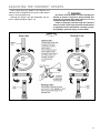
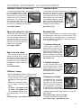
Owner's Manual Entire contents of manual must be read by owner Towing and Suspension Solutions ROADMASTER, Inc. • 6110 NE 127th Ave • Vancouver, WA 98682 800-669-9690 • fax: 360-735-9300 • roadmasterinc.com WELCOME TO THE ROADMASTER FAMILY! T his manual has been prepared to acquaint you with the assembly and operation of your tow dolly, and to provide you with important safety information. Read your owner’s manual cover to cover. Understand how to assemble and operate your tow dolly, and carefully follow the instructions and safety precautions. Your tow dolly has a one-year limited warranty. To qualify for your warranty, fill out and return the enclosed product registration card within 30 days of purchase. We thank you for your patronage. Record the serial number… Please record the serial number of your tow dolly in the space below. The number can be found at the front of the tongue, near the coupler. Have the model and serial numbers at hand when calling for technical support or replacement parts. It will allow us to serve you faster and ensure that you receive the correct components. Model number: RM 3477 Serial number: “Towing vehicle” and “towed vehicle” — definition People frequently confuse the terms “towing vehicle” and “towed vehicle.” The “towing vehicle” is the one that pulls the dolly, while the “towed vehicle” is on the dolly. To avoid confusion, the phrase “towing vehicle” has been replaced by “motorhome” (even though you may not be using a motorhome to tow the dolly). We will use the phrase “towed vehicle” as defined above. Specifications Minimum (inside) ramp width................................... 34" Maximum (outside) ramp width.............................77" Overall length........................................................ 121" Overall width.......................................................... 102" Height at fenders..................................................... 29" Weight - empty................................................ 545 lbs. Tires ......................................... radials ST 205/75 R14 Adjustable TieDown™ straps..................fit 12"-16" tires Coupler information .................... 2" ball diameter, 5,000-pound capacity Optimum trailer ball height...................................... 19" Max. weight of towed vehicle........................4,250 lbs. Actual cargo capacity....................................2,550 lbs. Required trailer ball size and capacity ...........................2" diameter, 5,000-pound capacity * Vehicles with fender flares, or with fenders that *overhang the wheels, may be susceptible to damage during cornering. Refer to step 1 in the “Towing” section, on page 9. IMPORTANT NOTICE! Safety Definitions Statements in these instructions identified as follows are of special significance: WARNING indicates a potentially hazardous situation which, if not avoided, could result in property damage, serious personal injury, or even death. CAUTION indicates a potentially hazardous situation which, if not avoided, may result in property damage, or minor or moderate personal injury. CAUTION used without the safety alert symbol indicates a potentially hazardous situation which, if not avoided, may result in property damage. NOTE Refers to important information and is placed in italic type. It is recommended that you take special notice of these items. TABLE OF CONTENTS Specifications.....................................inside front cover Safety Definitions...............................inside front cover Tow Dolly Safety Requirements.................................. 2 Before you assemble the dolly (pre-assembly instructions)..................................... 3 Initial Assembly ...................................................... 4-7 Using Your Tow Dolly............................................ 7-10 Before Loading....................................................... 7 Loading................................................................ 7-9 Towing.................................................................... 9 Unloading the Dolly........................................... 9-10 Pulling the Dolly Empty........................................ 10 Maintenance............................................................. 10 Adjusting the TieDown™ Straps................................ 11 Limited Warranty....................................................... 12 Pre-Trip Safety Checklist.............................back cover 1 TOW DOLLY SAFETY REQUIREMENTS Read all instructions before assembling or operating the tow dolly. Failure to understand how to assemble or operate the tow dolly could result in property damage, personal injury or even death. 1. The trailer ball, ball mount, receiver and motorhome must all be rated to pull a weight that exceeds the combined weight of the tow dolly, towed vehicle and all of its contents. 2. Do not pull more than 4,250 pounds with the tow dolly. Remember to add the weight of all contents within the towed vehicle when calculating its total weight. 3. The motorhome must be at least 1,000 pounds heavier than the towed vehicle. If not, the momentum of the towed vehicle and dolly will attempt to push the motorhome, resulting in “fishtailing” or “jackknifing.” This force can cause a loss of control that can result in severe damage or a life-threatening accident. 4. The tow dolly is equipped with electric brakes. For the electric brakes to function, a brake controller must be installed in the motorhome. Even with adequate braking capacity, the combination of vehicles will require additional stopping distance that must be accounted for when towing. Refer to the manufacturer's instructions to set the controller to the appropriate weight for towing; be certain to reduce the braking force if the dolly is ever towed unladen. 5. Avoid sharp turns when towing with the dolly loaded — always turn with as wide a radius as possible. Turning too sharply may cause the towed vehicle to contact the tow dolly fender, causing damage to the towed vehicle and dolly. 6. Do not back up the dolly when loaded. It will easily jackknife, which can damage the tongue, deck or other components. 7. Before loading any vehicle, be certain that the ramps are adjusted to the correct width. See the “Initial Assembly” section, steps 9 and 10, for further information. 8. Before unloading any vehicle, be certain that the pivot pin and safety clip have been removed, or severe damage to the tow dolly and towed vehicle will result. 9. Replace broken, worn or defective tow dolly components before towing any vehicle. 10. Torque the lug nuts to 90 ft./lbs. every 50 miles for the first 200 miles. Torque every 3,000 miles thereafter. 11. Inspect both tire’s air pressure every 3,000 miles. Inflate to the recommended psi listed on the tire sidewall. Do not tow on improperly inflated tires — the result will be premature tire wear. If towing the dolly unladen, reduce the tire pressure by 15 psi. Before each trip, inspect the tires for road damage or unusual wear patterns. 12. Always connect the dolly to the motorhome before 2 loading the towed vehicle. Similarly, always unload the towed vehicle before disconnecting the dolly from the motorhome. It is nearly impossible to control the combined weight of the dolly and towed vehicle when disconnected from the motorhome. 13. When connecting the safety chains to the motorhome, cross them underneath the coupler. If the coupler should ever disconnect, the crossed chains will support the tongue of the dolly, helping to prevent it from digging into the road. 14. The towed vehicle’s steering wheel must be locked or otherwise secured when towing. Failure to lock the steering wheel will allow the towed vehicle to pivot on the bed, causing it to hit the fender and wheel assembly of the dolly. Severe damage will result to both vehicles. 15. When loading and unloading, be careful not to burn yourself on any chassis or engine components that may still be hot. In addition, the underside of the vehicle may have sharp edges and corners that can cause cuts and abrasions. 16. Do not ride on the tow dolly or in the towed vehicle while it is being towed. 17. If the towed vehicle has rear wheel drive, be certain it can be towed without damaging the transmission. If necessary, drop the driveshaft to protect the transmission. 18. Always load the towed vehicle facing forward. Do not put a vehicle on the dolly backwards. The front end alignment on most vehicles prevents the steerable wheels from properly tracking the tow dolly. This can result in severe fishtailing and swaying, as well as unfavorable front end and tire wear. In addition, it may cause a loss of control, resulting in a severe, lifethreatening accident. 19. Check and comply with your local, state, federal or provincial requirements for towing. 20. The tow dolly is not designed for commercial applications. Commercial use will void the warranty. Failure to follow these instructions can cause property damage, personal injury or even death. BEFORE YOU ASSEMBLE THE DOLLY… Read all instructions before assembling or operating the tow dolly. Failure to understand how to assemble or operate the tow dolly could result in property damage, personal injury or even death. Musts for installation safety 1. Before starting the installation, lay out the kit components in order, as they will be used. This will give you a visual idea of how the components work, and will also confirm that everything is present and accounted for. 2. The assembler must use all bolts and parts supplied as instructed. 3. The assembler and owner must read and understand all instructions and heed all warnings within the owner’s manual, the literature packet and on the dolly before loading any vehicle onto the dolly. 4. The owner must check with and comply with all local, state, federal or provincial requirements regarding tow dollies. 5. The assembler must wear eye protection while assembling the tow dolly. 6. The assembler must show the owner how to properly load, unload and tow his vehicle. 7. The assembler must caution the owner to use a trailer ball, ball mount and receiver that are rated at 5,000 pounds or more. 8. Vehicles must be loaded with the front wheels on the dolly. 9. The owner must be certain that any rear wheel drive vehicle is towable on the dolly without damaging the transmission. Rear wheel drive vehicles may require a drive line disconnect to prevent transmission damage. 10. The assembler must lubricate the ramp wear strips. See page 6. If the ramp wear strips are not lubricated, the tow dolly will not track smoothly around corners. 11. The assembler must stress the importance of the owner sending in the product registration card. The warranty is only valid if the owner sends in his product registration card within 30 days. Warranty registration will allow us to expedite a claim or contact the customer should the need arise. Required tools and materials • (2) ¾" wrenches • (2) 9/16" wrenches • (2) 1½" crescent wrenches • a torque wrench and a box wrench • ¾" socket wrench with short extension • 9/16" socket wrench • 13/16" socket wrench • 15/16" wrench and 7/8" socket wrench with an extension • pair of wire strippers • pair of wire crimpers • silicone sealant (small tube) 3 INITIAL ASSEMBLY Although it is not necessary, it may be more convenient to attach the brake drums, fenders and wheels if the axle is supported with three jack stands or blocks, at a height of eight to 10 inches. Position one jack stand or block at the end of each axle, and one under the center arm. If you choose to support the axle, make certain that it cannot fall. Severe personal injury, as well as damage to the dolly, can result if the axle falls. 1. First, attach both of the brake drum spindle hub assemblies (Figure 1) to the axles — the drums are labeled “L” or “R”. Attach the “L” brake drum to the driver’s side axle, and the “R” brake drum to the passenger side axle. Position each brake drum spindle hub assembly so that the four holes align to the four holes in the axle, with the stamped “L” or “R” at the bottom (Figure 1). With the provided 12mm x 1.75 x 30mm bolts and lock washers, attach the brake drums from the inside of the hub assemblies (inset, Figure 1). Torque each bolt to 59 ft./lbs. Figure 1 Figure 2 The lock washers must be used, or the brake drum spindle hub assemblies will separate from the axle during use. Property damage, personal injury or even death can result if the brake drum spindle hub assemblies separate. 2. Attach the fenders — position both fenders so that the three pre-drilled holes (Figure 2) align to the three pre-drilled holes in the fender supports. Attach the fenders to the bolts with the 3/8"-16 x 1¼" bolts, flat washers (both sides) and nuts (Figure 2). Position the bolts so that the heads of the bolts will be facing the towed vehicle. Torque the bolts to 33 ft./lbs. 3. Attach the green and white wires extending from each brake drum to either of the two green wires on the corresponding hub assembly — if necessary, trim the wires to length. Connect the wires with the included butt connectors, then slide the pre-attached shrink wrap over the connection. Seal the shrink wrap with a heat gun or similar device, then cover the exposed wires with the included loom. 4. At both fenders, attach the electrical connectors (Figure 3). If the electrical connectors are not attached, the tow dolly brake lights and taillights will not work in tandem with those of the motorhome, which is required by law. Drivers behind the towed vehicle will not be alerted when the motorhome stops or turns, which 4 Figure 3 may cause a traffic accident. Failure to follow these instructions may cause property damage, personal injury or even death. continued on next page INITIAL ASSEMBLY continued from preceding page 5. Attach the wheels — at each 1 wheel, finger-tighten the five lug 4 3 nuts, then use the crossing pattern shown to the right to torque all five 2 5 lug nuts on both wheels to 90 ft./ lbs. Use this crossing (If the axle has been supported, pattern to tighten the lug nuts. remove it from the supports now.) 6. Attach the tongue — position the pre-drilled hole at the end of the tongue (Figure 4) so that it aligns to the pre-drilled hole on the front arm of the axle. Attach the tongue with the 5/8"-13 x 4½" bolt, cut washers (both sides), lock washer and lock nut (Figure 4). Hand-tighten the bolt for now — it will be adjusted after the dolly is completely assembled. 7. Insert the pivot pin through the pre-drilled holes in the front arm of the axle and the tongue (inset, Figure 4) and secure it in place with the safety pin (inset, Figure 4). 8. Attach the stabilizer bars — use the ½" x 4½" bolt, Figure 4 Figure 5 flat washers (both sides) and nut to attach the two stabilizer bars to the pre-drilled holes in the tongue, and the ½"-13 x 1¼" bolts and flat washers to attach the stabilizer bars to the tabs at the front of the axle, as shown in Figure 5. Attach the stabilizer bars to the axle so that they are to the outside of the tabs (inset, Figure 5), with the flat washers to the outside. Hand-tighten the three bolts for now — they will be adjusted after the dolly is completely assembled. 9. Attach the wiring harness — install a plug on the wire harness that matches the electrical socket on the motorhome, following the color code below. Wiring Color Code white........................................................... ground brown..................................taillights/running lights yellow................................................ left turn/stop green............................................... right turn/stop black........................................... power for brakes Apply a silicone sealant (not provided) to the wires where they attach to the plug — this will help prevent damage from moisture and corrosion. 10. Attach the ramps — first, slide both of the ramps over the axle (Figure 6). Then, on the inside of each ramp, align two of the U-brackets (Figure 6) over the pre-drilled weldment nuts. Attach each U-bracket to the ramps with two of the ½"-13 x 1½" bolts, flat washers, lock washers and nuts. Position the flat washers and lock washers to the inside. Torque the ½"-13 x 1½" bolts to 78 ft./lbs. 11. Slide the ramps to the left or the right, to correspond to the width of the towed vehicle's tires. Align the ramps so that both tires will be centered on the ramps, and so that the ramps will be an equal distance from the center of the axle. If the ramps are not adjusted as described above, continued on next page Figure 6 5 INITIAL ASSEMBLY continued from preceding page the dolly may veer to the left or the right during towing, which may cause a loss of vehicular control. Failure to follow these instructions may cause property damage, personal injury or even death. Figure 7 12. Once the ramps have been adjusted to the towed vehicle, screw in the four ½"-13 x 1" bolts with jam nuts (Figure 7) to the bottom of the four U-bolts. Torque the four bolts to 25 ft./lbs. Then, tighten the jam nuts against the bolts. If the bolts are not torqued to 25 ft./lbs., towing vibrations may work one or all of them loose, which will cause the ramp(s) to slide back and forth during towing. The ramps or other dolly components may be damaged. Figure 8 13. Position the deck spacer (Figure 8) over the predrilled 1-1/8" hole at the center of the axle. 14. Apply the supplied lubricant to the top of the deck spacer and the two ramp wear strips (inset, Figure 8). Lubricant must be applied to the deck spacer and ramp wear strips, or the dolly will not track smoothly around corners — it will jerk and jump. This “lurching” or “skipping” movement will be felt at the towing vehicle's steering wheel. Figure 9 15. Position the deck over the axle as shown in Figure 9, so that the pre-drilled holes at the center of the deck, deck spacer and axle align. 16. Attach the deck with the 1"-8 x 6" pivot bolt (Figure 9), flat washers (both sides) and nut. Torque the deck pivot bolt to 70 ft./lbs. Do not over-tighten the deck pivot bolt. If the deck pivot bolt is over-tightened, the deck will not pivot when the motorhome turns, which will apply extreme stress to the deck, the tongue, the straps and/or other components, which may cause them to fail. The towed vehicle or the dolly may separate from the motorhome, which may result in property damage, personal injury or even death. 17. The dolly is assembled. Now, tighten the tongue and stabilizer attachment bolts, which you attached in steps 6 and 8. First, one at a time, hand-tighten each of the bolts listed below. Then remove the pivot pin (Figure 4) and tilt the ramps to the ground. If the ramps tilt down, 6 tighten the bolt further. Repeat until the ramps do not tilt down. Then, loosen the bolt slightly and test to see if the ramps tilt down. When the ramps tilt down, the bolt is adjusted correctly. First, adjust the ½" x 4½" stabilizer bolt, as describedabove. Then, adjust the two ½"-13 x 1¼" stabilizer bolts. Adjust the 5/8"-13 x 4½" tongue attachment bolt last. Do not over-tighten the stabilizer and tongue attachment bolts. If the bolts are over-tightened, the deck will not tilt — vehicles cannot be loaded continued on next page INITIAL ASSEMBLY continued from preceding page onto the dolly. 18. Attach both ratchets — unscrew the 3/8” bolts from the ratchets, then reattach them through the sliding bars at the front of the deck, as shown to the right. USING YOUR TOW DOLLY Before Loading 1. Before loading the towed vehicle, make certain that the ramps have been adjusted to correspond to the width of the towed vehicle’s tires. See the “Initial Assembly” section, steps 10 and 11, for detailed instructions on how to adjust the ramps. 2. Check the vehicle weight — the tow dolly is rated at a maximum of 4,250 pounds. Verify that the weight of the towed vehicle and all of its contents does not exceed 4,250 pounds. 3. Check the trailer ball height — Make certain that the trailer ball height is 19 inches, plus 18"-20" or minus one inch. Ball heights outside of this range can create poor towing characteristics, such ground level as sway and fishtailing. In addition, incorrect ball height can cause the ramps to damage the bottom of the towed vehicle or drag on the road over bumps and dips. The coupler requires a two-inch hitch ball with a 5,000 pound capacity. Loading 1. Park the motorhome on a flat, level surface. Make certain that the motorhome engine is off, with the transmission in park, and that the emergency brake is on. 2. Position the dolly in line with the motorhome and place the coupler over the trailer ball. Make certain that the coupler socket fully encloses the hitch ball. Secure the coupler to the ball by fully lowering the coupler lever to a horizontal position (Figure 10). Pull up on the tow dolly tongue to verify that the coupler is properly latched and is securely attached to the trailer ball. Always connect the dolly to the motorhome before loading the towed vehicle. It is nearly impos- Figure 10 sible to control the combined weight of the dolly and towed vehicle when disconnected from the motorhome. Attempting to do so may cause property damage, personal injury or even death. 3. Attach the safety chains to the receiver on the motorhome and cross the chains, as shown in Figure 10. Crossing the safety chains will help prevent the tongue from catching on the road in case of disengagement. Leave just enough slack in the chains for turning corners. 4. Connect the tow dolly’s wiring plug to the motorhome’s socket and check the lights for proper function. 5. Remove the pivot pin (Figure 3), and tilt the ramps to the ground. The ratchet must be in the down position when loading. If the ratchet is left in the up position, it may catch on the towed vehicle, resulting in damage to the vehicle. continued on next page 7 USING YOUR TOW DOLLY continued from preceding page 6. If the towed vehicle has a rock guard, spoiler, air dam or other undercarriage component, check to ensure that it will clear the ramps and deck without damage. Now, align the towed vehicle with the dolly and have an assistant carefully guide you up the ramps, being careful to keep the towed vehicle centered. As the towed vehicle reaches the top, the ramps will automatically raise. Continue forward until the tires touch the ramp stop. All towed vehicles must be loaded forward, with the steerable wheels on the tow dolly. The front end of the towed vehicle is aligned with a small amount of “toe-in” to help keep it in a straight line as you drive. By towing backwards you reverse the effect, causing the towed vehicle to wander, sway and fishtail. This can cause loss of control, resulting in property damage, personal injury or even death. 7. Now, lock or otherwise secure the steering wheel so that the front end cannot pivot on the dolly. If the vehicle is not equipped with a locking steering column, you must secure the steering wheel so that it cannot turn while being towed. Failure to lock the steering wheel will allow the towed vehicle to pivot on the bed, causing it to hit the fender and wheel assemblies of the dolly. Severe damage will result to both vehicles. 8. Put front wheel drive vehicles in park. If the vehicle is a rear wheel drive, make certain it can be towed with the rear wheels on the ground without damaging the transmission. If it can be safely towed, put the towed vehicle in neutral. If not, remove the driveshaft and put in park (in gear if a manual transmission). Do not set the emergency brake if it applies the Figure 11 rear wheels, or severe brake damage or fire may result. 9. Re-install the pivot pin and properly secure with the safety pin (see Figure 3). 10. Now, secure the towed vehicle to the dolly with the TieDown™ straps — The hook (Figure 11) will always go toward the rear and the buckle will always be on the outside of the tire, as shown in Figure 11. Identify the passenger side strap (see “Adjusting the TieDown Straps,” page 11) and install it on the tire, as shown in Figure 11. Position the hook so that it is centered with the tire. As close as possible, adjust the diameter of the buckle strap so that the front and rear of the strap engage the tire just above the 9:00 Figure 12 and 3:00 positions. Rotate the buckle Push lever strap around the tire, down so that the strap is just forward of the center of the wheel. Next, pull the strap through Feed strap the buckle so that the from back side buckle is tight around and through the tire (Figure 12). Be certain that the TieDown straps do not touch any components behind the wheel, such as struts. If the TieDown straps are touching a strut or other component, road vibrations will cause the straps to be chafed while towing, which may cause the strap(s) to separate, resulting in property damage, personal injury or even death. Be certain that the TieDown strap is routed through the buckle, as shown in Figures 11 and 12, before towing. The strap will not secure the towed vehicle if the strap is not routed through the buckle correctly. Failure to properly route the strap will causethe strap to loosen, which may result in property damage, personal injury or even death. The crossover strap (Figure 11) should be centered at 12:00. In addition, center the ratchet with the tire, by sliding it to the left or right as necessary. Now, take the front end of the strap and feed at least six inches through the slot in the ratchet. Tighten the strap by raising and lowering the ratchet handle, as shown in the photo to the right. The strap is sufficiently tight when the tire begins to flatten continued on next page 8 USING YOUR TOW DOLLY continued from preceding page against the ramp stop. The ratchet handle must be in the down position when towing to properly secure the TieDown straps. If the ratchet handle is left up, the strap may loosen during towing, which may cause the towed vehicle to separate from the dolly, resulting in property damage, personal injury or even death. Be certain that the TieDown strap is centered on the tire, both front-to-rear and side-to-side, when tightened. Also, make certain that the strap is not twisted and cannot rub or chafe. Be certain to secure the end of the straps to prevent them from flapping and possibly damaging the finish of the towed vehicle or dolly. Repeat this procedure on the driver’s side. See “Unloading the Dolly” to release the TieDown straps. The TieDown straps must be retightened after towing the first five miles. Check the TieDown straps every 100 miles thereafter for tightness (as well as for any chafing or rubbing). Road vibrations may cause the TieDown straps toloosen during towing. If the TieDown straps are not tightened, the towed vehicle may separate, which will cause property damage, personal injury or even death. 11. Connect the auxiliary lighting for the rear of the towed vehicle. Test the lighting for proper function before towing. Note: nearly every state requires lighting at the rear of the towed vehicle. ROADMASTER manufactures three lighting systems: • The Universal Wiring Kit (part number 154) allows you to safely connect to and use the existing taillights of the towed vehicle. •The Taillight Wiring Kit (part number 155) bypasses the towed vehicle’s lighting with a set of independent plugs and sockets mounted inside the taillights. • Magnetic tow lights (part numbers 2100 and 2120) do not connect to the towed vehicle’s electronics. The magnetic lights are particularly useful if you tow multiple vehicles. Towing Before towing any vehicle for the first time, test to ensure that the vehicle will not come into contact with the dolly's fenders. Vehicles with fender flares, or fenders that overhang the wheels, are especially susceptible to damage of this kind. First, make certain that the towed vehicle is cen- tered on the dolly. In an empty parking lot, have someone watch as you slowly turn sharply to see whether you have this potential problem. Damage that results from turning too sharply is not covered by warranty. The combined motorhome, dolly and towed vehicle will take significantly longer to accelerate and pass other vehicles. Stopping distances may be greatly increased, as well. Failure to compensate for the tow dolly and towed vehicle while towing may result in a loss of vehicular control, which may cause property damage, personal injury or even death. If the tow dolly sways or fishtails while towing, bring the motorhome to a slow, controlled stop. Each of the following can cause or contribute to vehicle sway: towing a vehicle backwards; excessive weight in the rear of the vehicle; insufficient tire pressure; damaged rims or wheel bearings; excessive speeds; and unlocked steering wheel. Additionally, the towed vehicle’s wheels must be straight and square with the dolly. Towing a vehicle that sways excessively may cause a loss of control. Failure to correct excessive sway, as described above, may result in property damage, personal injury or even death. Unloading the Dolly 1. Stop the motorhome on flat ground with both vehicles in line. Turn the engine off, put the transmission in park and set the emergency brake. 2. If the driveshaft was removed for towing, replace it at this time. 3. Disconnect the wiring for the auxiliary lighting on the towed vehicle. 4. Remove the pivot pin and safety pin (Figure 3). 5. Unlock the ratchets — use your thumb to pull down the release bar while rotating the ratchet upwards, as shown to the right. The release bar will lock open when the ratchet has been rotated straight up. Unwind the strap from the ratchet and remove the TieDown straps. After removing the TieDown straps, lower the ratchets to prevent the vehicle from catching on them while unloading. Otherwise, the tow dolly and/ or the towed vehicle may be damaged. continued on next page 9 USING YOUR TOW DOLLY continued from preceding page 6. Have an assistant guide you off the dolly. As you begin to back up, the ramps will tilt to the ground. Continue slowly down the ramps until the towed vehicle is completely off the dolly. Always unload the towed vehicle before disconnecting the dolly from the motorhome. It is nearly impossible to control the combined weight of the dolly and towed vehicle when disconnected from the motorhome. Attempting to do so may cause property damage, personal injury or even death. 7. Store the TieDown straps in a clean, dry place. If the dolly is to be left outdoors for long periods of time, remove the straps or any other items that can be damaged by moisture. 8. Disconnect the safety chains and wiring plug from the motorhome. 9. Disconnect the dolly from the trailer ball by raising the coupler latch. Pulling the Dolly Empty When empty, the dolly is likely to bounce around behind the motorhome. It is advisable to reduce the tire pressure by 15 psi to help alleviate bouncing and vibration. Be certain that the tires are reinflated to the correct pressure before loading a towed vehicle. Reduce the tire pressure when towing the dolly empty. If the tire pressure is not reduced, as described above, the dolly will bounce and vibrate excessively. The dolly ramps and/or other components may be cracked or otherwise damaged. 1. The coupler must be secured. 2. Safety cables and wiring must be attached to the motorhome. 3. Before towing, verify that the lighting functions correctly on the dolly. MAINTENANCE 1. Torque the wheel lug nuts to 90 ft./lb. Check and maintain every 3,000 miles or every six months. 2.TieDown™ ratchets — check and maintain every 3,000 miles or every six months — use a drop of oil to lubricate the moving components of the ratchets. Do not over-lubricate — excessive oil will attract dirt and road film, preventing the proper operation of the ratchet. 3. TieDown straps — check and maintain every 3,000 miles or every six months — inspect the straps, hooks and adjustment buckles for any damage or excessive wear. Promptly replace straps if damaged in any way. 4. Accu-Lube™ hubs — lubricate and check before the initial operation, and lubricate every time before you tow. To lubricate the hubs: 1. Remove the rubber plug. 2. Insert a grease gun into the grease fitting. Note: do not use air-powered grease guns. 3. Pump the grease gun until the old grease comes back out the front. 4. Remove the old grease and reinsert the plug. 5. Coupler adjustment — check and maintain every 3,000 miles or every six months — if the coupler does not properly engage the ball, simply tighten the lock nut. (Do not overtighten the nut, or the lever will not lock.) 10 6. Tires — check and maintain every 3,000 miles or every six months. Tires should be inflated to the recommended psi listed on the tire sidewall; under-inflated tires will have excessive wear. 7. Ramp wear strips and deck spacer — grease every six months to a year, depending on use. Use axle grease, fifth wheel kingpin grease or hitch grease; apply a liberal amount of grease to the top of the wear strips and spacer. Lubricant must be applied to the deck spacer and ramp wear strips, or the dolly will not track smoothly around corners — it will jerk and jump. This “lurching” or “skipping” movement will be felt at the towing vehicle’s steering wheel. ADJUSTING THE TIEDOWN™ STRAPS Even though they may appear to be identical, one TieDown strap is designed for the driver’s side and the other for the passenger side. Although the straps come pre-assembled, the process is explained below (Figure 13). Be certain that the strap is routed through the buckle, as shown in Figure 13, before towing. The strap will not secure the towed vehicle if it is not routed through the buckle correctly. Failure to properly route the strap will cause the strap to loosen, which may cause the towed vehicle to separate from the motorhome, resulting in property damage, personal injury or even death. Figure 13 11 LIMITED WARRANTY 1.WARRANTY 1a.WARRANTY OF CONFORMITY AT TIME OF SALE ROADMASTER, Inc. warrants that at the time of sale of this product it will be free from defects in material and manufacture and will conform to ROADMASTER’S specifications for the product. 1b.CONDITIONAL ONE-YEAR WARRANTY In addition to the preceding time-of-sale warranty, if the product registration card is completely and accurately filled out and mailed to ROADMASTER within thirty (30) days of purchase, ROADMASTER will provide an additional warranty that for a period of one year after sale the product will remain in good working order, PROVIDED THAT the product is installed and maintained in accordance with ROADMASTER’S instructions and is not subjected to: (a) alteration or unauthorized repairs or repairs by anyone other than ROADMASTER or a ROADMASTER-authorized service center, (b) misuse, abuse, commercial use, or improper maintenance, (c) Acts of God (including without limitation hurricanes, tornadoes, floods, or other severe weather or natural phenomena), (d) failures due to products not supplied by ROADMASTER, or (e) other treatments, uses, or installations for which the product was not intended. This warranty extends only to the first retail purchaser-consumer of the product and is not transferable. become the property of ROADMASTER. ROADMASTER will not provide, and will not be liable for, labor, costs of removal or reinstallation of components, disposal, shipping, freight, taxes, or other incidental charges. 2.DISCLAIMER OF OTHER WARRANTIES The preceding warranties are the exclusive and sole express warranties given by ROADMASTER. They supersede any prior, contrary or additional representations, whether oral or written. No agent, representative, dealer or employee has the authority to alter or increase the obligations or limitations of this warranty. Any implied warranties, including the WARRANTY OF MERCHANTABILITY and any WARRANTY OF FITNESS FOR A PARTICULAR PURPOSE, are limited in duration to thirty days or the term of the applicable express warranty provided above, whichever is longer. Some states do not allow limitations on how long an implied warranty lasts, so the above limitation may not apply to you. 4.DISCLAIMER OF INCIDENTAL AND CONSEQUENTIAL DAMAGES IN NO EVENT SHALL ROADMASTER BE LIABLE FOR ANY INCIDENTAL, SPECIAL, INDIRECT OR CONSEQUENTIAL DAMAGES, WHETHER RESULTING FROM NONDELIVERY OR FROM THE USE, MISUSE OR INABILITY TO USE THE PRODUCT OR FROM DEFECTS IN THE PRODUCT. Some states do not allow the exclusion or limitation of incidental or consequential damages, so the above limitation may not apply to you. 3.EXCLUSIVE REMEDY FOR ANY NONCONFORMITIES If during the applicable Warranty Period, the product does not conform to the preceding Warranties, notify ROADMASTER as provided below, and within a reasonable time ROADMASTER will provide, at its option, one of the following: (1) replacement components for any nonconforming or defective product or components or (2) the percentage of the purchase price for the nonconforming product equal to the percentage of the Warranty Period remaining when ROADMASTER is notified of the nonconformity. ROADMASTER will, at its option, (a) use new and/or reconditioned parts in performing warranty repairs and making replacement products, (b) use parts or products of original or improved design in the repair or replacement. If ROADMASTER repairs or replaces a product, its warranty continues for the remaining portion of the original Warranty Period or 60 days from the date of the return shipment to the customer, whichever is greater. All replaced products and all parts removed from repaired products 12 THESE REMEDIES ARE THE EXCLUSIVE AND SOLE REMEDIES FOR ANY BREACH OF WARRANTY. For any breach of warranty, the Owner must telephone ROADMASTER at 1-800-669-9690 within thirty (30) days after discovering the nonconformity. Do not return any product without first calling ROADMASTER and getting a return authorization number. Returned products must include the return authorization number and a copy of the original invoice, bill or other proof of the date of purchase. The date of purchase must coincide with the original warranty registration card on file. ROADMASTER will authorize (a) shipment of the product to ROADMASTER or (b) repair or replacement at the nearest warranty service center—in both cases with shipping at your expense. Do not purchase replacement parts or pay for repair labor—you will not be reimbursed. Compliance with the requirements of this paragraph is a condition to coverage under the Warranty: if these requirements are not complied with, ROADMASTER will have no obligation to provide any remedy for any breach of warranty. 5.APPLICABLE LAW This Warranty will be interpreted, construed, and enforced in all respects in accordance with the laws of the State of Washington, without reference to its choice of law rules. The U.N. Convention on Contracts for the International Sale of Goods will not apply to this Warranty. 6.SEVERABILITY If any provision of this warranty is found to be invalid or unenforceable, then the remainder shall have full force and effect, and the invalid provision shall be partially enforced to the maximum extent permitted by law to effectuate the purpose of the agreement. 7.ADDRESS FOR NOTICES TO ROADMASTER ROADMASTER, Inc., 6110 NE 127th Ave., Vancouver, WA 98682 This warranty gives you specific legal rights, and you may also have other rights which vary from State to State. OPTIONAL EQUIPMENT and ACCESSORIES Guardian™ carrier for tow dolly TieDown ratchet Using this mounting bracket, you can add the protection of ROADMASTER's Guardian tow shield to your tow dolly. Helps protect your towed vehicle against rocks, gravel and other road debris. The all-steel, powder-coated bracket bolts on or off in seconds, and can be attached anywhere on the tow dolly arm. (Guardian not included) part number 2000-8 Heavy-duty, solid steel construction for trouble-free performance, durability, greater strength and safety in securing your towed vehicle. Zinc plating helps prevent rust and corrosion. Non-binding design for easy release — to unlock the ratchet, simply pull down the release bar while rotating the ratchet upward. part number 2110 Spare tire carrier for tow dolly Electrical kits Mount your spare tire and wheel on your tow dolly using this heavyduty steel, powder-coated mounting bracket. Bolts on or off in seconds, and can be attached anywhere on the tow dolly arm. (spare tire not included) part number 2000-7 By law, a towed vehicle's turn signals, running lights and brake lights must mimic the motorhome's. There are three ways to accomplish that: 1) a system of diodes; 2) installing new taillights in the towed vehicle; or 3) magnetic tow lights. Spare tire and wheel This optional spare tire and wheel eliminates costly delays and flat tire hassles. Heavy-duty ST 215/75 R14 radial trailer tire mounted on a wheel to match the RoadMaster tow dolly. (fender not included) part number 2000-9 TieDown™ straps Why are RoadMaster TieDown straps the best? • One strap fits the driver's or passenger's side. • Tough, durable nylon resists damage from rubbing and chaf ing. • Heavy-duty, 7,700-pound capac ity for superior strength and safety 14" strap — part number 2114 15" strap — part number 2115 Or, for maximum flexibility, order the universal strap — fits 12" to 16" tires. Universal strap — part number 2150 1. Universal wiring kit This kit uses a system of diodes to safely connect your motorhome's turn signals, running lights and brake signals to the towed vehicle's. Diodes prevent electrical feedback, and protect both vehicles' electrical systems. part number 154 2. Taillight wiring kit A self-contained wiring system that bypasses your towed vehicle's lighting with a set of independent plugs and sockets mounted inside the taillights. part number 155 3. Magnetic tow lights ROADMASTER's magnetic tow lights are the quick and easy way to connect your towed vehicle's electrical system to your motorhome's. The system is self-contained, and requires no splicing into the towed vehicle's electrical system. Magnetic lights are particularly handy if you tow multiple vehicles. part number 2100 — deluxe tow lights (includes case and anti-scratch pads) part number 2120 — standard tow lights 13 PRE-TRIP SAFETY CHECKLIST Coupler is securely latched to trailer ball. Safety chains are attached to motorhome. Electrical harness is plugged into motorhome, and dolly lights are functioning properly. Auxiliary lighting is connected to towed vehicle and is functioning properly. Pivot pin and safety pin have been inserted. Towed vehicle and its contents weigh less than 4,250 pounds. Towed vehicle is centered on and square with the tow dolly. Towed vehicle’s steering wheel is locked or otherwise secured. Towed vehicle is in the correct gear for towing (see towed vehicle’s owner's manual). TieDown™ straps are centered on the tires and tightened properly. TieDown straps are not twisted and cannot chafe or rub. Ratchets are in the down position for towing and unloading. Wheel lug nuts are torqued to 90 ft./lbs. The Accu-Lube™ hubs have been lubricated. Tire pressure is correct for towing — loaded or unloaded. The nuts securing the fenders are tight. The nuts and bolts securing the tongue and stabilizers are tight. The ramp wear strips and deck spacer have been lubricated within the past six months. (see the Maintenance section, page 10) The safety checklist above is not all-inclusive. Read, understand and follow all instructions and warnings within the tow dolly and towed vehicle owner’s manuals. All photos, illustrations and specifications contained herein are based on the latest information available at the time of publication. ROADMASTER, Inc. reserves the right to make changes at any time, without notice, in material, specifications and models, or to discontinue models. You may not use any of the contents of this document without the permission of ROADMASTER, Inc. © 2009 ROADMASTER, Inc. All rights reserved. Towing and Suspension Solutions ROADMASTER, Inc. • 6110 NE 127th Ave • Vancouver, WA 98682 800-669-9690 • fax: 360-735-9300 • roadmasterinc.com 854258-03 10/2009