1
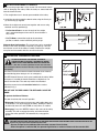
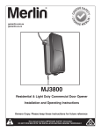
gomerlin.com.au
gomerlin.co.nz
MT100EVO
Sectional and Tilt Garage Door Opener
Installation and Operating Instructions
Owners Copy: SAVE THESE INSTRUCTIONS for future reference
This manual contains IMPORTANT SAFETY information
DO NOT PROCEED WITH THE INSTALLATION BEFORE READING THOROUGHLY
WARNING!
START BY READING THESE IMPORTANT SAFETY INSTRUCTIONS
• Failure to comply with the following instructions may result in serious personal injury or property damage.
• Read and follow all instructions carefully.
• The garage door opener is designed and tested to offer safe service, provided it is installed and operated in
strict accordance with the instructions in this manual.
These safety alert symbols mean WARNING : A possible risk to personal safety or property
damage exists.
Keep garage door balanced. Do not let the garage door
opener compensate for a binding or sticking garage door.
Sticking, binding or unbalanced doors must be repaired
before installing this opener.
The Protector SystemTM must be used for all installations
where the closing force as measured on the bottom of the
door is over 400 N (40 kgf). Excessive force will interfere with
the proper operation of the Safety Reverse System or damage
the garage door.
SPECIAL NOTE: Merlin strongly recommends that The
Protector SystemTM be installed on all garage door openers.
Do not wear rings, watches or loose clothing while
installing or servicing a garage door opener. Wear gloves,
safety goggles and suitable protective clothing where
appropriate.
After installation, ensure that the parts of the door do not
extend over public footpaths or roads.
Install the wireless wall control (or any additional wall control) in
a location where the garage door is visible, at a height of at
least 1.5 m and out of the reach of children. Do not allow
children to operate push button(s) or transmitter(s). Serious
personal injury from a closing garage door may result from
misuse of the opener.
Frequently examine the door installation, in particular
cable, springs and mountings for signs of wear, damage or
imbalance. Do not use if repair or adjustment is needed
since springs and hardware are under extreme tension
and a fault can cause serious personal injury.
To avoid serious personal injury from entanglement,
remove all ropes, chains and locks connected to the
garage door before installing the door opener.
Permanently fasten the Warning Labels in Prominent Places,
adjacent to Wall Controls and on manual release mechanism as
a reminder of safe operating procedures.
Installation and wiring must be in compliance with your
local building and electrical codes.
The safety reverse system test is very important. Your
garage door MUST reverse on contact with a 40 mm
obstacle placed on the floor. Failure to properly adjust the
opener may result in serious personal injury from a closing
garage door. Repeat the test once a month and make
any necessary adjustments.
Activate opener only when the door is in full view, free of
obstructions and the opener is properly adjusted. No one
should enter or leave the garage while the door is in motion.
Automatic Door- The door may operate unexpectedly, therefore
do not allow anything to stay in the path of the door.
Do not allow children to play near the door, or with door
controls. Keep remotes away from children.
This appliance is not intended for use by persons
(including children) with reduced physical, sensory or
mental capabilities, or lack of experience and knowledge,
unless they have been given supervision or instruction
concerning use of the appliance by a person responsible
for their safety.
Disconnect electric power to the garage door opener before
making repairs or removing covers.
If the supply cord is damaged, it must be replaced by the
manufacturer, its service agent or similarly qualified persons in
order to avoid hazard.
Use the Manual Release only for the seperation of the
carriage from the drive and - if possible - ONLY with the
door closed. Do not use the red handle to push the door
up or pull it down. Operation of the emergency release can
lead to uncontrolled movements of the door, if springs are
weak or broken or if the door is unbalanced. Mount the
release handle of the emergency release at a height less
than 1.8 m from the floor.
This opener should not be installed in a damp or wet space
exposed to weather.
To avoid damage to very light doors (such as fibreglass,
aluminium or steel doors), an appropriate reinforcement should
be added. To do so, contact the door manufacturer.
SAVE THESE INSTRUCTIONS
Warning: If your garage has no service entrance door, a E1702M outside quick release must be installed. This
accessory allows manual operation of the garage door from outside in case of power failure.
CONTENTS
PAGE
INSTALL WIRELESS WALL
SAFETY INSTRUCTIONS . . . . . . . . . . .1
BUTTON . . . . . . . . . . . . . . . . . . . . . . . .14
BEFORE YOU BEGIN . . . . . . . . . . . . . .2
TIMER TO CLOSE . . . . . . . . . . . . . . . .14
DOOR TYPES . . . . . . . . . . . . . . . . . . . .2
INSTALL WARNING LABELS . . . . . . .15
CARTON INVENTORY . . . . . . . . . . . . .3
PARTIAL OPENING FEATURE . . . . . .15
RAIL SIZES . . . . . . . . . . . . . . . . . . . . . .3
WIRELESS PROGRAMMING . . . . . . .16
TOOLS REQUIRED . . . . . . . . . . . . . . . .4
USING YOUR OPENER . . . . . . . . . . .17
HARDWARE PROVIDED . . . . . . . . . . . .4
CARE OF YOUR OPENER . . . . . . . . .17
COMPLETED INSTALLATION . . . . . . . .4
REPLACE BATTERIES IN
CONTROL PANEL . . . . . . . . . . . . . . . . .5
REMOTE . . . . . . . . . . . . . . . . . . . . . . .17
ASSEMBLY . . . . . . . . . . . . . . . . . . . . . .6
ACCESSORIES . . . . . . . . . . . . . . . . . .18
INSTALLATION . . . . . . . . . . . . . . . . .7-10
REPLACEMENT PARTS . . . . . . . . . . .19
OPERATE THE MANUAL RELEASE . .10
TROUBLESHOOTING . . . . . . . . . . 20-21
ADJUSTMENT . . . . . . . . . . . . . . . .11-12
SPECIFICATIONS . . . . . . . . . . . . . . . .22
INSTALL THE PROTECTOR
WARRANTY . . . . . . . . . . . . . . . . . . . . .23
SYSTEM (OPTIONAL) . . . . . . . . . . . . .13
1
BEFORE YOU BEGIN:
1. Look at the wall and ceiling above the garage door. (The opener and header bracket must be securely fastened to structural
supports.)
2. Do you have a finished ceiling in your garage? If so, a support bracket and additional fastening hardware (not supplied) may
be required.
3. Do you have an access door in addition to the garage door? If not, model E1702M Outside Quick Release Accessory is
required. This accessory allows manual operation of the garage door from outside in case of power failure.
4. Complete the following test to make sure your garage door is balanced and is not sticking or binding:
• Lift the door about halfway. Release the door. If balanced, it should stay in place, supported entirely by its springs.
• Raise and lower the door to see if there is any binding or sticking, 20 kgf is the absolute maximum allowable force to raise or
lower the door in any position. If your door binds, sticks, or is out of balance, call a trained door technician.
1 DOOR TYPES
A.
B.
C.
D.
Sectional Door with curved track
One-Piece Door with Horizontal Track Only
One-Piece Door without track
J-Type tilt Door fittings
C
A
NOTE: When installing an opener on J-Type (D) tilt
doors, ensure the PIVOT POSITION No. 1 is used.
Pivot postitions 2 and 3 progressively increase the
force required to operate the door and are not
recommended, or approved with this opener.
D
To suit spring balanced Residential Sectional &
Tilt doors up to 20 m2.
PIVOT POSITION
M10 Coach Screw
See Detail
Pivot Position No. 1
Electrical Connection
A 240 V General Purpose Outlet (GPO) ie. Power Point must be available in close proximity to the powerhead.
This fitting is not part of the Opener hardware and must be supplied by the consumer.
In the event of a power outage or the unit being disconnected from the power source, the door MUST be operated and
supervised so that it completes a full UP and DOWN cycle with no obstructions in place to ensure that the unit
automatically checks that the safety force settings are correct.
2
2 CARTON INVENTORY
Your garage door opener and rail are packed in two seperate cartons. The tiltmaster MT100EVO opener carton contains the
opener, its fitting hardware and accessories. The rail carton contains the rail and some hardware.
Rails:
Different length rails (2.2 m & 2.4 m) are available for different height doors, ensure you have the correct one.
(1) Opener
(2) Hand held transmitter (2)
(3) Wireless wall control
(4) Curved door arm
(5) Hanging bracket (2)
(6) Rail bracket
(7) Header bracket
(8)
(9)
(10)
(11)
(12)
(13)
(14)
Door bracket
Hardware bag
Rail assembly (separate carton)
C-Rail bracket (2)
Tilt door bracket
Manual
Warning Labels
4
1
2
5
3
6
9
7
11
8
12
gomerlin.com.au
gomerlin.co.nz
14
For Service Call
MT100EVO
Installation Date
Sectional and Tilt Garage Door Opener
13
114A3361
Installation and Operating Instructions
RISK OF ENTRAPMENT
Repeat Safety Reverse Test monthly Door
must reverse on contact with a 40mm obstacle
placed on the floor Make necessary adjustments
AUTOMATIC DRIVE:
Keep away from the area of the door since it may
operate unexpectedly
EMERGENCY RELEASE:
To release pull down firmly on the red handle
OwnersCopy:SAVETHESEINSTRUCTIONSforfuturereference
132A2900
IMPORTANTSAFETYinformation
TALLATIONBEFOREREADINGTHON2966
ROUGHLY
This manual contains IMPORTANT SAFETY information
DO NOT PROCEED WITH THE INSTALLATION BEFORE READING THOROUGHLY
N2966
10
3 RAIL SIZES AVAILABLE
DOOR HEIGHT:
Sectional Doors
BELT & RAIL
PART NUMBER:
RAIL LENGTH:
CEILING FIXING
POINTS: (standard)
ALTERNATE
FIXING POINT:
Up to 2.2 m
8022 CR5
3000 mm single piece
2840 mm
2950 mm
Up to 2.2 m
8322 CR5
(not for use on J-type
tilt doors)
3000 mm segmented
2840 mm
2950 mm
Up to 2.4 m
8024 CR5
3200 mm single piece
3040 mm
3150 mm
From 2.4 - 3.4 m
840 CR5
1000 mm extension
4040 mm
4150 mm
2.3 m TILT Door
820 CR5
2000 mm single piece
1840 mm
1950 mm
NOTE: The Ceiling Fixing Point (Standard) is the position of the hanging bracket measured back from the lintel (see
item 1 to 7 of “completed installation”). Also allow 400 mm back from the fixing point for installation of the powerhead
(item 7 to 9 of “completed installation”).
The Alternate Fixing Point will position the hanging bracket between the C-Rail brackets, and may line up with a
structural support more favourably.
3
4 TOOLS REQUIRED
Drill Bits
10
5 HARDWARE PROVIDED
1 (1x)
3 (4x)
2 (1x)
(1) Clevis pin 80 mm
(2) R clip
(3) Hexagonal head screw
(4) Nut M8
(5) Flat washer M8
(6) Clevis Pin
(7) R clip
(8) Screw ST6 x 50 mm
(9) Screw ST6,3 x 18 mm
(10) Wallplug 8mm
4 (4x)
5 (4x)
8 (4x)
7 (1x)
9 (8x)
6 (1x)
10 (4x)
6 COMPLETED INSTALLATION
As you proceed with the assembly, installation and adjustment procedures in this manual, you may find it helpful to
refer back to this illustration of a completed installation.
4
14
7
1
2
3
5
4
8
15
6
9
11
10
13
12
(1) Header bracket
(2) Belt
(3) Rail
(4) Trolley
(5) Rail connecting piece
(6) Rail bracket
(7) Hanging bracket
4
(8) Power cord
(9) Opener
(10) Manual release rope & handle
(11) Straight door arm
(12) Curved door arm
(13) Door bracket
(14) C-Rail brackets
(15) Centre rail bracket
7 CONTROL PANEL (located under the cover at the rear of the opener)
1. External Accessory Power: 30 Vdc 50 mA available for universal receiver (not active in Low standby mode).
2. Terminal Block: used for external accessories (see chart below).
No
Function
Colour
Polarity
Comment
0
E-Serial port
Green
+ve
Serial Communication Input
1
Push button
Red
+ve
Dry Contact input for push button wired wall controls
2
Ground
White
-ve
Common terminal for push button
2
Ground
White
-ve
Common terminal for IR Beams
3
IR Sensor
Gray
+ve
Merlin IR Beam Input: (pulsing type only)
4
Door-in-door
Green
+ve
For Door in Door dry contact sensor: (4&5 are normally linked)
5
Door-in-door
Green
-ve
Common terminal for Door in Door sensor
6
Flasher
Black
+ve
Flashing light output: (24 Vdc 150 mA) while door is in motion
7
Flasher
White
-ve
Flashing light output: negative terminal
3. UP Button: used for initial programming, to drive the door UP, and for displaying Diagnostic Code - Digit 1.
4. PROG Button: used to program door limits, and other features.
5. DOWN Button: used for initial programming, to drive the door DOWN, and for displaying Diagnostic Code - Digit 2.
6. LEARN Button: used to program remote controls and learn the forces manually.
7. Indicator LED: used to indicate various programming modes.
8. Green Button: used to activate the door when remote controls are not available. Open - Stop - Close via finger
access through the hole in the access cover.
2
1
30 V DC
+
0
1
2
2
3
4
5
6
7
-
3
8
INDICATOR
LED
UP
PROG
LEARN
(YELLOW)
DOWN
7
6
5
5
4
8 ASSEMBLING THE 3 PIECE SEGMENTED RAIL
ASSEMBLY SECTION
NOTE: For 1 piece preassembled rails, proceed to the next step “TIGHTEN THE BELT”.
NOTE: Not for use on J-type tilt doors.
The segmented rail is largely preassembled and consists of 3 parts. The carriage, push rod, release handle, the guide pulley
and the lintel bracket with belt tensioner are in the front part (A). The seating for the drive shaft and the sprocket are in the
rear part (B). Hardware items are placed in the rails during transportation - remove these. Lay the front and rear rail sections
one behind the other.
1. Remove cable ties that secure the belt.
2. Pull apart the two rail sections completely in order to create a gap for the middle section (C). This rail is designed in such a
way so as to easily add the middle section. Slide the 2 connecting pieces (D) over the seams of the rail sections up to the
markings. To secure the connecting pieces, bend the sheet metal lugs outwards with a suitable tool. The assembly of the rail is
complete.
9 TIGHTEN THE BELT
Note: The spring must be able to compress and bounce
during operation. Final tensioning can be performed after
installation if necessary. Over tightening the belt may
overload the system and cause excessive wear.
37 - 41 mm
1
1.Tension the belt by adjusting the nut (1), on the pulley
assembly, clockwise until the spring is engaged.
2.Continue tightening to compress the spring and remove all
the slack in the belt. DO NOT OVERTIGHTEN but ensure belt
is firm.
3.37-41 mm as indicated in the diagram is normal.
10 FASTEN RAIL TO OPENER
1.Slide the RAIL BRACKET (1) onto the powerhead end of the
rail (A) around 200 mm.
2.Position the rail drive spocket (2) over the opener motor shaft
(3) and push down to install.
3.Secure the rail on the opener with two C-Rail brackets (4) and
the screws (5).
This completes the assembly of the door opener to the rail.
A
1
5
4
2
3
6
INSTALLATION SECTION
Wear protective goggles when working overhead to protect your eyes from injury.
Disengage all existing garage door locks to avoid damage to the garage door.
To avoid serious personal injury from entanglement, remove all ropes connected to the garage door before
installing the opener.
11 HEADER BRACKET POSITIONING
The header bracket must be rigidly fastened to a
structural support of the garage. Reinforce the wall or
ceiling with a 40 mm (1-1/2") board if necessary. Failure
to comply may result in improper operation of safety
reverse system.
You can attach the header bracket either to the header wall
(1) or to the ceiling (3). Follow the instructions which will
work best for your particular requirements.
With the door closed, mark the vertical centre line (2) of the
garage door. Extend line onto header wall above the door.
Open door to highest point of travel. Draw an intersecting
horizontal line (4) on header wall 50 mm for Sectional
Doors, and up to 200 mm for Tilt Doors, above high point to
provide travel clearance for top edge of door.
3
1
4
2
3
12 INSTALL THE HEADER BRACKET
NOTE: Refer to vertical centre and horizontal lines created in
the previous section for proper placement of header bracket.
A. Wall mount: centre the header bracket (1) on the vertical
centre line (2) with the bottom edge of the header bracket on
the horizontal line (4) (with the arrow pointing toward the
ceiling). Drill and secure the Header Bracket using the most
suitable variation of holes (5). If using the wood screws
provided, uses a 4.5 mm pilot drill. If securing to a metal fixture,
self tapping “tek” screws may be more suitable.
B. Ceiling mount: extend vertical centre line (2) onto the ceiling.
Centre the header bracket (1) on the vertical mark no more
than 150 mm (6") from the wall. Make sure the arrow is pointing
toward the opener. Drill and secure the Header Bracket using
the most suitable variation of holes (5). If using the wood
screws provided, uses a 4.5 mm pilot drill. If securing to a metal
fixture, self tapping “tek” screws may be more suitable. For
concrete ceiling fixtures, 8 mm wall plugs are provided.
2
3
4
5
up to
200 mm
2
(50 to 200 mm depending on door type)
50 mm
A
1 2
150 mm
(6")
3
Attach the Rail to the Header Bracket
• Position the assembled opener on the garage floor below the
header bracket. Use foam packing material as a protective
base.
• Position the rail bracket against the header bracket.
• Align the bracket holes and secure with the 80 mm clevis pin
and “R” clip (1) and (2).
7
1
3
4
5
13 ATTACH RAIL TO HEADER BRACKET
NOTE: If the door spring is in the way youʼll need help.
Have someone hold the opener securely on a temporary
support to allow the rail to clear the spring.
1
1
2
14 POSITION THE OPENER
Disengage the trolley mechanism (see section “Operating the manual release”) and slide it back towards the powerhead.
Secure the hanging push arm up into the rail assembly temporarily using tape or rope, to avoid a hazard.
SECTIONAL DOOR OR TRACKED TILT DOOR
Rail
You will need a 50 mm piece of timber or similar
spacer to gauge the distance between door and rail.
Header 50 mm (2”)
Bracket above the highest
point of travel
1.Raise the opener onto support.
50 mm spacer should
be used to determine
the correct mounting
position
Door
2.Open the door completely, place a 50 mm spacer between
the door and the rail (as shown).
3.The final positioning of the rail should be relatively parallel
to the horizontal door panels.
50 mm (2”)
above the highest
point of travel
ONE PIECE TILT DOOR
Rail
Header
Bracket
You will need a 50 mm piece of timber or similar spacer to
gauge the distance between door and rail.
Door
50 mm spacer should
be used to determine
the correct mounting
position
1.Raise the opener onto support.
2.Open the door completely, place a 50 mm spacer between
the door and the rail (as shown).
Header
Bracket
3.The top of the door should be level with the top of the
opener. Do not position the opener more than 50 mm
above this point.
Ensure the opener is not positioned too low as to cause a
hazard to vehicles or persons.
up to 200 mm (8”)
above the highest
point of travel
50 mm spacer should
be used to determine
the correct mounting
position
8
Door
Rail
15 HANG THE OPENER
The opener must be securely fastened to a sound
structural support above the opener.
A
X
fig.1
1.Postion the opener as in the previous step. Check the rail
is centred over the door.
Ensure the rail brackets (fig.1) is on the Powerhead end of
the rail in a position as close to the opener as possible (X).
2.If mounting directly onto the ceiling, (fig.2) screw the
bracket directly into a structural support on the ceiling.
fig.2
fig.3
fig.4
3.If hanging the opener below the ceiling, (fig.3) bend the
hanging brackets provided, and secure to both the ceiling
and the rail bracket.
4.If installing a segmented rail, a centre rail bracket is
supplied for installation in the mid position of the rail.
Simply slip both halves over the top of the rail (fig.4), and
secure to the ceiling, either directly or with hanging strips.
5.Check the opener is securely centred over the door.
Remove the 50 mm spacer, and any other assembly
tools. Operate the door manually and check for
unrestricted operation.
16 FASTEN DOOR BRACKET
The door bracket must be securely fastened to the frame
or a structural support on the door.
A
Mounting position for Sectional Doors
1.Align the bracket on the centre line, measure down 100300 mm from the door top edge.
100-300 mm
2.Secure the bracket in this position, using the most
suitable variation of holes available.
Mounting Position for one Piece Doors
1.Align the door bracket on the centre line on a structural
Top edge of the door (use the door bracket that best suits
the situation).
2.Secure the bracket in this position, using the most
suitable variation of holes available.
1
9
(tilt door bracket)
17 ATTACH DOOR ARM TO TROLLEY
Make sure the garage door is fully closed. Pull the manual release
cord to disengage the trolley. Slide the trolley to around 300 mm
from the header bracket.
1.The straight door arm is already preassembled to the trolley.
2.Install the curved arm onto the door bracket using the Clevis pin
(2) and R-Clip (3) supplied.
3.Move the straight and curved arms together and secure using
two bolts and nuts provided (4).
Fig. 1
Fig. 2
5
3
1
4
2
- For Sectional Doors: ensure the angle of the straight
arm is around 20 degrees from vertical, when the door is
fully closed.
Fig. 3
- For Tilt Doors: extend the length to the maximum
position, to obtain a more horizontal pushing angle.
Alternate Arm Configuration: The curved arm can be assembled
directly to the trolley assembly if required (see figure 3). Unscrew
the front two screws in the trolley assembly. Remove the straight
arm pivot and reassemble with the curved arm bracket.
Trolley Screws
18 OPERATING THE MANUAL RELEASE
DO NOT DISENGAGE THE OPENER TO MANUAL
OPERATION WITH CHILDREN , PERSONS OR OTHER
OBJECTS INCLUDING MOTOR VEHICLES WITHIN THE
DOORWAY : (The door is under significant tension and if the door
has developed a fault or incorrect tension, it may be unsafe and may
fall rapidly.)
The manual release mechanism enables the door to be manually
operated during power outages or in an emergency.
The RED Manual Release cord is preassembled to the trolley. When
the opener is installed the handle should be no higher then 1.8
metres from the floor. The cord may need to be extended.
Attach the manual release Instruction Label to the cord as
indicated in fig 1.
DO NOT USE THE RED HANDLE TO OPEN AND CLOSE THE
DOOR.
Instruction
label
1
2
To operate the Manual Release:
The door should be fully closed if possible.
1.Disengage: Pull the manual release rope and handle down once
to disconnect. This will disengage the trolley, allowing the door to
be moved by hand, UP and DOWN as many times as needed.
2.Re-engage: Press the “GREEN” button in the centre of the trolley
assembly. This will re-engage the trolley, and when the door
passes the trolley position it will automatically re-engage the
opener.
Connect Electric Power
TO AVOID INSTALLATION DIFFICULTIES, DO NOT RUN THE GARAGE DOOR OPENER UNTIL INSTRUCTED TO DO SO.
Connect to properly fused and earthed power outlet.
- Ensure all ropes and installation tools have been removed from the door.
- When the opener is switched ON, the operator light flashes a number of times and then remains ON.
10
19 PROGRAM THE TRAVEL LIMITS AND FORCE SETTINGS
ADJUSTMENT SECTION
Travel limits regulate the points at which the door will stop
when moving UP or DOWN. The travel limit buttons are located
under the access cover on the rear panel (figure 1).
figure 1
NOTE: This opener uses a POSITION TAB attached to the belt
which activates a mechanical passpoint during the door travel.
The indicator LED will blink when this occurs. If the passpoint
is not activated during the door travel process, the travel limits
cannot be programmed.
TO PROGRAM THE TRAVEL LIMITS:
1. Press the PROG Button until the UP Arrow Button and indicator
LED begin to flash (figure 2).
2. Press and hold the UP Arrow Button until the door is in the
desired UP position (figure 3).
NOTE: The UP and DOWN Arrow Buttons can be used to move
the door up and down as needed.
3. Once the door is in the desired UP position press and release the
PROG Button. The DOWN Arrow Button will begin to flash (figure
4).
4. Press and hold the DOWN Arrow Button until the door is in the
desired DOWN position (figure 5).
NOTE: The UP and DOWN Arrow Buttons can be used to move
the door up and down as needed.
5. Once the door is in the desired DOWN position press and release
the PROG Button. The UP Arrow Button will begin to flash (figure
2).
SETTING THE FORCE (AUTO):
6. Press and release the UP Arrow Button to test the UP limit. When
the door has travelled to the programmed UP limit, the DOWN
Arrow Button will begin to flash.
7. Press and release the DOWN Arrow Button to test the DOWN
limit. The door will travel to the programmed DOWN limit.
The indicator LED will stop flashing. The travel limits and force
setting has now been set. Proceed to test safety reverse system.
SETTING THE FORCE (MANUAL LEARN IF REQUIRED):
1. Open the rear access panel. Locate the yellow Learn button.
2. Push the yellow Learn button twice to enter unit into force
adjustment mode. The LED (indicator light) will flash quickly.
3. Push the programmed remote control or push the UP/DOWN
arrow at the programming display bar. The door will travel to the
DOWN (close) position. Push the remote control again, the door
will travel to the UP (open) position.
4. Press and release the DOWN Arrow Button to test the DOWN
limit. The door will travel to the programmed DOWN limit.
The LED (indicator light) will stop flashing when the force has
been set. The door must travel through a complete cycle, UP
and DOWN, in order for the force to be set properly. If the unit
cannot open and close your door fully, inspect your door to insure
that it is not sticking or binding.
The Force Setting has now been set manually.
11
Without a properly installed safety reversal
system, persons (particularly small children)
could be SERIOUSLY INJURED or KILLED by
a closing door.
• Incorrect adjustment of garage door travel limits will
interfere with proper operation of safety reversal
system.
• NEVER use force adjustments to compensate for a
binding or sticking garage door.
• After ANY adjustments are made, the safety reversal
system MUST be tested. Door MUST reverse on
contact with 40 mm high object laid flat on floor.
To prevent damage to vehicles, be sure fully open
door provides adequate clearance.
figure 2
Indicator LED
figure 3
Indicator LED
figure 4
Indicator LED
figure 5
Indicator LED
20 TEST THE SAFETY REVERSE SYSTEM
The safety reverse system test is important. Garage door must reverse on contact with a 40 mm obstacle
laid flat on the floor. Failure to properly adjust opener may result in serious personal injury from a closing
garage door. Repeat test once a month and adjust as needed.
Procedure: With door opened place a 40 mm obstacle (1)
laid flat on the floor under the garage door. Operate the
door in the down direction. The door must reverse off the
obstacle. If the door stops on the obstacle, remove obstacle
and repeat Program the Limits and Force Steps, then
repeat safety reverse test.
When the door reverses off the 40 mm obstacle, remove
the obstacle and run the opener through a complete travel
cycle. Door must not reverse in closed position. If it does,
repeat Program the Limits and Force then repeat safety
reverse test.
40mm
1
21 PROGRAM THE TRAVEL SPEED (OPTIONAL)
40mm
1
TRAVEL SPEED: Automatically selected:
There are two travel speeds available for this opener.
The speed is a function of door travel distance and is automatically set during the door travel limit setting process.
* Travel distance longer then 2 metres = REGULAR speed
* Travel distance shorter than 2 metres = SLOW speed (will suit tilt doors best.)
TRAVEL SPEED: Manually selected:
The speed can be set manually if required, once the travel limits have been set, using the following method.
To activate the alternate speed:
PRESS and HOLD both the UP and DOWN arrows for 3 seconds.The courtesy lamp will flash once to confirm SLOW
speed and twice to confirm REGULAR speed.
To deactivate the selected speed: Repeat the process above (toggle between the two settings).
22 PROGRAM THE LOW STANDBY MODE (OPTIONAL)
Low Standby Mode (sub 1 watt) is activated by the factory to deliver the lowest possible standby power.
In this mode the External Accessories Power and the IR Beams are turned OFF when the door is closed and the courtesy light
is OFF.
At mains turn ON: Courtesy light flashes 2 times = Low Standby Mode
Courtesy light flashes 10 times = Normal Standby Mode
The Normal Standby Mode will need to be activated for External Accessories Power.
To Activate Normal Standby Mode:
Turn the mains power OFF.
PRESS and HOLD both the UP and DOWN arrows simultaneously.
Turn ON mains power while both the arrow buttons are still pressed.
Courtesy light comes on and after 5 seconds another 10 flashes.
Release the arrow buttons.
To Activate Low Standby Mode:
Turn the mains power OFF.
PRESS and HOLD both the UP and DOWN arrows simultaneously.
Turn ON mains power while both the arrow buttons are still pressed.
Courtesy light comes on and after 5 seconds another 1 flash.
Release the arrow buttons.
12
23 INSTALL THE PROTECTOR SYSTEMTM (OPTIONAL)
NOTE: This accessory must be used for all installations
where the closing force as measured on the bottom of the
door is over 400 N (40 kgf).
SPECIAL NOTE: Merlin strongly recommends that The
Protector SystemTM be installed on all garage door
openers.
IR BEAMS: By installing IR Beams, an open door is prevented
from closing if a person or object is located in the beam area. If
the door is already closing, it will return to the open position. A
closed door is not prevented from opening.
If the Protector SystemTM is installed and needs to be removed,
the opener will need to be reprogrammed (refer to paragraph 4
of the troubleshooting section).
To prevent entrapment, install The Protector
System™ no higher than 100 mm above the floor.
Disconnect power to the garage door opener
before installing The Protector System™.
figure 1
ALL INSTALLATIONS
Mount Bracket
With Square Holes
NOTE: A complete set of installation and setup
instructions are supplied with the accessory item.
“C” Wrap
Screws
Lock Nuts
Figures 1, 2 and 3 show recommended assembly of bracket(s)
and "C" wrap based on the wall installation of the sensors on
each side of the door shown above, or on the door tracks
themselves. Figure 4 shows variations which may fit your
installation requirements better. Make sure the wraps and
brackets are aligned so the sensors will face each other
across the door.
figure 2
TM
Installing The Protector System
to the Garage Wall
Carriage Bolts
(with Square Shoulders)
Lag Screws
• Connect each assembly to a slotted bracket, using the
hardware shown. Note alignment of brackets for left and
right sides of the door. Finger tighten the lock nuts.
• Use bracket mounting holes as a template to locate and drill
two (4.8 mm) diameter pilot holes on both sides of the door so
that the beam mounting height is no greater than 100 mm
above the floor.
• Attach bracket assemblies with carriage bolts as shown.
• Adjust right and left side bracket assemblies to the same
distance out from mounting surface. Make sure all door
hardware obstructions are cleared. Tighten the lock nuts.
• Centre each sensor unit in a "C" wrap with lenses pointing
toward each other across the door.
• Secure sensors with the hardware provided. Finger tighten
the wing nut on the receiving eye to allow for final adjustment.
Securely tighten the sending eye wing nut.
• Run wires from both sensors to the opener and connect the
two white only wires to the white terminal (2) and the
black/white wires to the grey terminal (3) on your opener (refer
figure 5).
Garage
Wall
“C” Wrap
Mounting Bracket
with slot
Mounting Bracket
with Square Holes
Lock Nuts
figure 3
Installing The Protector SystemTM to Track
Lock Nuts
Garage
wall
Garage
Track
Mounting Brackets
with Square Holes
Drill
9.5 mm
Holes
“C” Shaped
Wrap
Carriage Bolts
Alternate Floor Mount
Alternate Wall Mount
Garage
Wall
Garage
Wall
Mounting
Bracket
with Holes
figure 5
Indicator
Lamp
Sensor
Mounting Bracket
with Square Holes
Mounting Bracket
with Square Holes
“C” Wrap
Sensor
6mm
To release wires press
tab with a screwdriver
or pen
13
Garage
Floor
Indicator Light
figure 4
Holder
GarageFloor
Mounting Bracket
with Slot
Attach with
concrete anchors
(not provided)
24 TIMER TO CLOSE FEATURE (TTC)
Door may operate unexpectedly, therefore do not
allow anything to stay in the path of the door.
figure 1
The Timer to Close feature requires The Protector SystemTM
(IR Beams) to be installed.
Indicator LED
Operation:
This feature allows the door to automatically close from a fully
open position after a specified time. The delay can be set from
10 to 180 seconds in 10 second increments, by using the
opener control buttons.
If the door encounters an obstruction while closing, the door
will stop and return to the UP position. The Courtesy lamp will
then flash 10 times.
figure 2
Indicator LED
To Activate TTC, or change a preset time:
1.Start with the door fully CLOSED.
2.Enter into TTC Activation mode by pressing both PROG
and DOWN buttons together for 3 seconds (figure 1).
Release when the courtesy light flashes twice.
3.Press the UP button once for each 10 second increment
required of TTC (figure 2. eg. twice for 20 seconds). Press
the DOWN arrow to reduce, if needed.
4.Press and release the PROG button to save this time
(figure 3), Courtesy light will flash once. TTC is now
activated.
figure 3
Indicator LED
TEST: Operate the door to the UP position. Keep clear of the
IR Beams and check the door closes after the preset time.
To Deactivate TTC:
1.Enter into TTC Activation mode by pressing both PROG
and DOWN buttons together for 3 seconds (figure 1).
Release when the courtesy light flashes twice.
2.Press and release the PROG button to save (figure 3),
courtesy light will flash once. TTC is now deactivated.
figure 4
or
25 INSTALLING YOUR E138M WIRELESS WALL BUTTON
NOTE: The wall control supplied with your opener should be pre-programmed by the factory.
If adding a new wall control, program into the opener before mounting the unit as detailed in Wireless Programming.
Disconnect power to the opener before installing
this accessory to prevent accidental activation.
Locate minimum 1.5 m above the floor.
To install:
• Carefully pry open the E138M and locate the two screws for
mounting.
• Attach to the wall using the two screws provided. If mounting to a
plaster wall, wall plugs may be required.
NOTE: Do not overtighten screws.
• Replace the front cover plate.
14
+
26 INSTALL WARNING LABELS
figure 1
m
m
B
www
@
service
A
2
1
-
r
3
F
I
S
t ll t
C ll
D t
For Service Call
Installation Date
114A3361
RISK OF ENTRAPMENT
Repeat Safety Reverse Test monthly. Door
must reverse on contact with a 40mm obstacle
placed on the floor. Make necessary adjustments.
AUTOMATIC DRIVE:
Keep away from the area of the door since it may
operate unexpectedly.
EMERGENCY RELEASE:
To release, pull down firmly on the red handle.
132A2900
Three warning labels are provided with this opener: attach as indicated in the fig 1 to a clean and suitable surface.
1. Risk of entrapment: (English version) - place close to a fixed Wall Control(1).
2. EMERGENCY Release/Service label: - place on the Manual Release cord (2).
3. WARNING Child Entrapment: (triangle label) - place on a low inside panel of the door (3).
27 PARTIAL OPENING FEATURE (PET)
This is an adjustable, second stop position suitable for
ventilation, pedestrian or pet access, programmed to the Remote
Control.
figure 1
To Activate this feature:
1.Start with the door fully CLOSED (figure 1). Drive the opener
UP and stop at the position required for PET access.
2.Enter PET activation mode by pressing the PROG and UP
buttons together for 3 seconds (figure 2). Release when the
Courtesy light flashes once.
3.Press the Remote Control button that you have allocated for
this feature (figure 3). Do not use the button already allocated
for normal operation. The Courtesy light will flash once when
the code is accepted.
TEST: Press the Remote Control once, and door will close, press
again, and door will return to the preset position.
If the door is above the preset position, when the button
is pressed, it will fully close.
To Deactivate this feature:
1.Start with the door fully CLOSED.
2.Enter PET deactivation mode by pressing the PROG and UP
buttons together for 3 seconds (figure 1). The Courtesy light
will flash twice, indicating the deactivation has occurred.
NOTE: Erasing all remote control codes, as in the Wireless
programming section, will also delete this feature.
15
Indicator LED
figure 2
Indicator LED
figure 3
or
28 WIRELESS PROGRAMMING (OPTIONAL ACCESSORIES)
Activate the opener only when door is in full view, free of obstruction and properly adjusted. No one should
enter or leave garage while door is in motion. Do not allow children to operate push button(s) or remote(s).
Do not allow children to play near the door.
NOTE: The transmitter(s) and wireless wall button supplied with
your opener are preprogrammed by the factory.
If you purchase additional transmitters, the garage door opener must
be programmed to accept the new remote code.
2
Yellow “Learn” Button
Program the Receiver to Match Additional Transmitter Codes:
Using the yellow “LEARN” Button
1.Press and Hold the button on the hand-held remote or wall button that
you wish to use (1).
1
2.Press and release the yellow “LEARN” buton on the opener (2).
3.Release the remote button when the opener light flashes. It has learnt
the code. If you release the remote control push button before the
opener light flashes, the opener has not learned the code.
Now the opener will operate when the remote control push button is
pressed.
To Erase all Remote Control Codes
1.Press and Hold the yellow “LEARN” button on the opener until the
indicator LED goes ON, and continue holding for approx. 6 seconds,
until the indicator LED goes out.
1.Release the button, all codes are now erased.
Wireless Keypad E840M
2
3
To set the keyless entry PIN:
1.Locate the yellow “LEARN” button on the garage door opener.
4.Press and hold the ENTER button. Check to see if the opener light
flashes. Release the ENTER button after the light flashes.
To change an existing keyless entry PIN:
1.Enter the existing programmed PIN that you want to change.
Press and release
the yellow
learn button
3
Enter a 4-digit
PIN of your
choice
????
____
2.Press and release the yellow “LEARN” button. The LED indicator
light will glow steadily.
3.Enter a 4-digit personal identification number (PIN) of your choice
on the keypad.
Locate
the yellow
learn button
1
4
Press and hold
the enter button
Opener light flashes
2.Press and hold the # button until the courtesy light flashes twice.
3.Enter the new 4-digit PIN of your choice, then press the ENTER
button. The light will flash once.
4.To test, enter the new PIN, then press the ENTER button. The
garage door opener will activate.
16
After the lights
flash release the
ENTER button
29 USING YOUR OPENER
MAINTENANCE AND CARE OF YOUR OPENER
31 REPLACE BATTERIES IN REMOTES
Battery of the remote control:
1. Your opener can be activated by any of the following devices:
• Opener control panel: Up and Down Buttons and Green O.S.C.
• The Outside Keyswitch or Keyless Entry System (if you have
installed either of these accessories).
• The Remote Control Transmitter. Hold the push button down until
the door starts to move.
The batteries in the remote have an extremely long life.
If the transmission range decreases, the batteries must be
replaced. Batteries are not covered by the warranty.
To prevent SERIOUS INJURY OR DEATH:
observe the following instructions for the
battery
- NEVER allow small children near batteries.
- If battery is swallowed, immediately notify doctor.
- Danger of explosion if battery is replaced improperly.
- Replacement only by identical or equivalent type.
- Dispose of old battery properly. Batteries should not
be treated as household waste. All consumers are
required by law to dispose of batteries properly at the
designated collection points.
- Never recharge batteries that are not meant to be
recharged.
- Do not short-circuit batteries or take them apart.
- If necessary, clean contacts on batteries and contacts
before loading.
- Never expose batteries to excessive heat such as
sunshine, fire or the like!
2. Opening the Door Manually: Door should be fully closed if
possible. Weak or broken springs could allow an open door to
fall rapidly. Property damage or serious personal injury could
result.
NOTE: For full instructions on how to operate the door manually
refer to section 18.
The door can be opened manually by pulling the release handle
down. To reconnect the door, press the Green button in the centre of
the trolley assembly.
Do not use the manual release handle to pull the door open
or closed.
3.
1.
2.
3.
4.
5.
6.
7.
When the Opener is Activated by Remote Control:
If open, the door will close. If closed, the door will open.
If closing, the door will stop.
If opening, the door will stop (allowing space for entry and exit of
pets and for fresh air).
If the door has been stopped in a partially open or closed position,
it will reverse direction.
If an obstruction is encountered while closing, the door will reverse
to the UP limit.
If an obstruction is encountered while opening, the door will
reverse and stop.
The optional Protector System™ uses an invisible beam which,
when broken by an obstruction, causes a closing door to open
and prevents an open door from closing. It is STRONGLY
RECOMMENDED for homeowners with young children.
Replacing battery (CR2032):
To replace battery, turn remote control around and open the
case with a screwdriver. Lift cover and lift control board below.
Slide battery to one side and remove. Observe polarity of
battery!
Assemble again in reverse direction.
4. The opener lights will turn on under the following conditions:
when the opener is initially plugged in; when power is restored after
interruption or when the opener is activated.
Lights will turn off automatically after 2-1/2 minutes.
30 CARE OF YOUR OPENER
Once a Month
• Manually operate door. If it is unbalanced or binding, call a
qualified door technician.
• Check to be sure door opens & closes fully. Adjust limits
and/or force if necessary.
• Repeat the safety reverse test. Make any necessary
adjustments.
Once a Year
• Lightly grease the belt and inside the rail assembly where
the trolley slides.
• Internally the opener does not require additional lubrication.
• Lightly grease the belt and inside the rail assembly where
the trolley slides. Be careful to use gloves around any sharp
metal edge or the rail.
12
Pb
Cd
VD
C
Hg
To replace battery for optional remote control transmitters E943M, E940M & E945M, use a screwdriver blade to pry
open the case as shown. Insert battery positive side up.
Carefully
Remove Battery
(CR2032 x 1)
17
or
32 ACCESSORIES
(1)
(2)
(3)
(4)
(5)
(6)
Model
Model
Model
Model
Model
Model
E128M
E138M
E950M
E940M
E943M
E945M
Wireless wall button
Wireless wall button
4 Channel remote control
1 Channel visor remote control
3 Channel visor remote control
3 Channel mini remote control
E138M
E128M
1
E840M
(7) Model E840M
(8) Model C77
(9) Model E1702M
(10) Model 760E
(11) Model FLA24
E940M
E950M
2
3
E945M
E943M
5
4
760E
E1702M
C77
Keyless entry system
The Protector SystemTM
Quick release lock
Outside keyswitch
Flashing light
6
FLA24
11
10
9
NOTE: Only genuine Merlin accessories are approved for use with this opener. Generic compatible accessories are NOT approved for use with this opener.
7
8
33 RAIL HARDWARE
002A1800
Trolley with rope &
straight arm
004C5600
Hardware bag
041A4038
Pulley assembly
041A4020R
Sprocket assembly
041A4017-1
Motor shaft adapter (metal)
083A0011
Grease
One piece rail asssembly
8022CR5 2.2 m
8024CR5 2.4 m
Segmented rail
assembly
8322CR5
041A4016R
Position tab (belt)
Se
c
4 1 b ra
40 ail
A
r
1
04 nted
e
gm
es
Se
n
tio
42 sec
0
4 il
1 A ra
04 ted
en
gm
Replacement belt packs
041A4045-1 (2.2m)
041A4045-2 (2.4m)
041A4021R
Trolley latch (belt)
s
178A0104
Curved arm
178A0103
Straight arm
004C5502
Door bracket
012C0778
Hanging brackets
041A4036
Centre Rail bracket
012C0788-1
Header bracket
041A4039
C-Rail bracket
012A1027
Tilt Door bracket
18
012A1028
Rail bracket
34 REPLACEMENT PARTS
If the supply cord is damaged, it must be
replaced by the manufacturer, its service
agent or similarly qualified persons
in order to avoid hazard.
Power Cord
026B0181
041A4022A
Logic Board / PCB Housing / Control Cover (assembly)
041A4004
Passpoint
Assembly
041A4002-1
LED Module
041A4027
Transformer
041A4023-1
Power Board
041A4034
Motor Assembly
041A1805
Lens Cover
041A1803
Chassis Cover
041A1804
Brand Cover
RAIL REPLACEMENT PARTS
041A4017-1
Motor shaft adapter (metal)
041A4021R
Trolley latch (belt)
041A4016R
Position tab (belt)
19
35 TROUBLE SHOOTING
7. Door opens but won't close:
1. Opener doesn't operate from either door control or
remote:
• Check The Protector System™ (if you have installed
this accessory). If the light on the Beams are flashing,
correct the alignment.
• If opener light does not flash and it is a new installation,
repeat Programming the Travel Limits.
• Does the opener have electric power? Plug lamp into
outlet. If it doesn't light, check the fuse box or the circuit
breaker. (Some outlets are controlled by a wall switch.)
• Have you disengaged all door locks? Review installation
instruction warnings on page 1.
• Is there a build-up of ice or snow under door? The door
may be frozen to ground. Remove any obstruction.
• The garage door spring may be broken. Have it
replaced.
Repeat the safety reverse test after the adjustment is
complete.
8. Opener strains:
2. Door operates from door control but not from
remote:
Door may be unbalanced or springs are broken. Close
door and use manual release rope and handle to
disconnect trolley. Open and close door manually. A
properly balanced door will stay in any point of travel
while being supported entirely by its springs. If it does
not, call for professional garage door service to correct
the problem.
• Replace batteries in the remote if necessary.
• If you have two or more remotes and only one operates,
review Program Your Opener, Remote and Keyless
Entry.
9. Opener hums briefly, then won't work:
3. Remote has short range:
• Garage door springs are broken. SEE ABOVE.
• If problem occurs on first operation of opener, door is
locked. Disable door lock.
• Check the battery in the remote is fully charged.
• Change the location of the remote control in the car.
• A metal garage door, foil-backed insulation or metal
siding will reduce the transmission range.
Repeat safety reverse test after adjustment is complete.
4. Door reverses for no apparent reason and opener
light flashes 10 times:
10. Opener won't activate due to power failure:
• Pull manual release rope and handle down once to
disconnect trolley. Door can be opened and closed
manually. When the power is restored, press the
“GREEN” button in the centre of the trolley assembly.
The next time the opener is activated, the trolley will reconnect.
• The Outside Quick Release accessory (if fitted)
disconnects the trolley from outside the garage in case
of power failure.
• Check The Protector System™ (if you have installed this
accessory). If the light is flashing, correct alignment.
If the Protector SystemTM is installed and needs to be
removed, the Opener will need to be reprogrammed as
follows:
• Remove the IR Beam wiring from the Opener
• Turn the power OFF for 5 seconds
• Turn the power ON for 5 seconds
• Again turn the power OFF for 5 seconds
• Turn the power back on and test the opener for normal
operation.
11. The opener runs, but the carriage does not move:
• Check the carriage is not disengaged from the opener.
Operate the manual release to reengage the opener.
• In a new installation, the preassembled Motor Shaft
Adapter may have fallen out of the belt sprocket
assembly. This adapter is installed during the
manufacturing process and may have dislodged.
5. The garage door opens and closes by itself:
Make sure remote push button is not stuck "on".
6. Door stops but doesn't close completely:
12. The Up and DOWN arrows on the control panel
are flashing in sequence:
Repeat Programming the Travel Limits.
Repeat safety reverse test after any adjustment of door
arm length, close force or down limit adjustments.
Check the diagnostic code on next page.
20
36 DIAGNOSTIC CHART
Your garage door opener is programmed with self-diagnostic capabilities. The UP and DOWN arrows on the garage opener flash the diagnostic
codes.
DIAGNOSTIC CODE
UP Arrow DOWN Arrow
Flash(es)
Flash(es)
SYMPTOM
1
1
1
2
The garage door opener will not
close and the courtesy light flashes.
1
3
The door control will not function.
1
4
The garage door opener will not
close and the courtesy light flashes.
5
There is no door movement or motor
accelerates before stopping
suddenly.
1
6
Door continues to move after the
motor stops.
2
1-5
Opener fails to operate.
2
6
3
2
Unable to set travel limit down
direction. Passpoint has not been
recognised during programming.
1
The garage door opener will not
close and the courtesy light flashes.
POSSIBLE RESOLUTION
Safety sensors are not installed, connected or wires may be cut. Inspect
sensor wires for a disconnected or cut wire.
There is a short or reversed wire for the safety sensors. Inspect safety sensor
wire at all staple points and connection points and replace wire or correct as
needed.
The wires for the door control are shorted or the door control is faulty. Inspect
safety sensor wire at all staple points and connection points and replace wire
or correct as needed.
Safety sensors are misaligned or were momentarily obstructed. Realign both
sensors to ensure both LEDs are steady and not flickering. Make sure nothing
is hanging or mounted on the door that would interrupt the sensors path while
closing.
No RPM pulses have been detected. Check the door manually for balance,
binding or obstructions. Internally the possible cause may be the motor, logic
board or RPM sensor. Try resetting door travel limits. Contact service centre.
RPM pulses have been detected after motor has turned off. Possible broken
spring. Check the door is correctly balanced and not creeping up or down.
Contact a door service centre.
Possible logic board failure. Reboot opener by turning the mains power OFF
and then ON after 15 seconds. Reprogram the door travel limits and force
settings. Contact service centre.
Check the passpoint module has been activated by the belt Position Tab,
during the door travel. Reset the travel limits.
Unable to set the travel or retain
position.
Check travel module for proper assembly, replace if necessary.
Door is moving stops and or
reverses.
Manually open and close the door. Check for binding or obstructions, such as
a broken spring or door lock. If the door is binding or sticking contact a trained
door systems technician. If door is not binding or sticking attempt to reprogram
travel (refer to page 24 ).
Opener runs approximately 150 mm
to 200 mm, stops and reverses.
Communication error to travel module. Check travel module connections,
replace module if necessary.
Check the external wiring to the control panel terminal is wired correctly. Turn
off power, remove all external wiring, and retest door operation.
3
3
4
1-4
4
5
4
6
The garage door opener will not
close and the courtesy light flashes.
5
1-4
Door fails to operate or operates
erractically. External accessory
wiring failure.
5
5
Door opener fails to operate
The battery status LED* is constantly Battery backup charging circuit error, replace logic board. *(if applicable)
flashing green.
Safety sensors are misaligned or were momentarily obstructed. Realign both
sensors to ensure both LEDs are steady and not flickering. Make sure nothing
is hanging or mounted on the door that would interrupt the sensor's path while
closing.
Low internal voltage on the Logic Board, possible power transformer or logic
board failure. Service required, call a trained service specialist.
21
37 SPECIFICATIONS - tiltmaster - MT100EVO
Input Voltage...........230-240 Vac, 50 Hz
Max. Pull Force ......1000 N
Power .....................225 Watt
Standby Power .......0.8 Watt (door fully closed)
Normal Torque ........7 Nm
Max door weight......130 kgs Spring balanced
Max door area.........Sectional door Tilt Doors 20 m2
Motor
Type........................DC gearmotor permanent lubrication
Noise level ..............54 db at 1 metre
Drive Mechanism
Drive .......................Belt with one-piece trolley on
steel rail.
Length of Travel......Adjustable to 3.0 m
LED light .................25 Watt equivalent
Door Linkage ..........Adjustable door arm. Pull cord trolley release.
Safety
Personal .................Push button stop in UP and DOWN direction. Automatic safety reverse in both UP and DOWN
direction.
Electronic................Automatic force adjustment
Electrical .................Transformer overload protector and low voltage push button wiring.
Limit Device ............Mechanical Passpoint/RPM sensor
Limit Adjustment .....Electronic
Soft-start/Soft-stop
Dimensions
Length (Overall).......3.24 m
Headroom Required 30 mm
Hanging Weight .......12 kg
Receiver
Memory Registers ...64 handset codes
4 keypad devices - 1 code each
Operating
Frequency.................433.30/433.92/434.54 MHz
Warranty Registration
To validate your warranty you must complete
the registration form online at:
gomerlin.com.au/warranty
or
gomerlin.co.nz/warranty
TM
Trademark of The Chamberlain Group, Inc.
® Registered Trademark of The Chamberlain Group, Inc.
© 2014, The Chamberlain Group Inc.
22
CHAMBERLAIN LIMITED WARRANTY
Merlin® Professional Tiltmaster® MT100EVO
Sectional Garage Door Opener
Chamberlain Australia Pty Limited / Chamberlain New Zealand Limited
(Chamberlain), the manufacturer of Merlin® automatic garage door openers,
is committed to manufacturing and supplying high quality goods. As part of
this commitment, we seek to provide reliable service and support for our
goods and are pleased to provide you, the original purchaser, with this
Chamberlain Limited Warranty.
The benefits given to you under this Chamberlain Limited Warranty are in
addition to any rights and remedies that you may have under Australian or
New Zealand consumer protection laws. Our goods come with guarantees
that cannot be excluded under the Australian Consumer Law, or New Zealand
Consumer Guarantess Act 1993. You are entitled to a replacement or refund
for a major failure and for compensation for any other reasonably foreseeable
loss or damage. You are also entitled to have the goods repaired or replaced
if the goods fail to be of acceptable quality and the failure does not amount to
a major failure.
Chamberlain’s warranty
What is covered
Chamberlain warrants to the original purchaser of the Merlin Tiltmaster
MT100EVO Sectional Door Opener (Unit) that all parts of the Unit, other than
remote controlled transmitters and accessories, globes and batteries, are free
from defects in materials and workmanship for a period of 84 months or
15,000 cycles (each opening & closing of the garage door equals 1 cycle)
whichever comes first, from the date of purchase when installed by a
Professional dealer appointed or authorised by Chamberlain in a residential
premise with a residential specified garage door that is designed for the sole
purpose of a single-family dwelling.
Chamberlain warrants that remote controlled transmitters and accessories
included with the Unit are free from defects in materials and workmanship for
a period of 12 months from the date of purchase.
What is not covered
Batteries and globes are not covered under the Chamberlain Limited
Warranty.
Travel costs incurred by Chamberlain or the Professional Dealer in either
travelling to or from areas outside a capital city metropolitan area. These costs
will be at the purchaser’s expense.
Additional access costs incurred by a Professional Dealer or Chamberlain in
obtaining access where the Unit is not readily accessible. These cost will be at
the purchaser’s expense.
Warranty Conditions
It is a condition of this Chamberlain Limited Warranty that the Unit is sold,
installed and serviced by a Professional Dealer appointed or authorised by
Chamberlain. A Merlin branded garage door opener purchased over the
internet and installed by a person other than a Professional Dealer will not be
covered by this Chamberlain Limited Warranty.
It is also a condition of this Chamberlain Limited Warranty that for the
operating life of the Unit:
1 the garage door is spring balanced, is operable by hand and opens
and closes with no more than a maximum of 20 kgs of lifting weight;
2 the garage door and the Unit is professionally maintained and serviced
by a Professional Dealer, at a minimum, during the third and fifth years
of the Chamberlain Limited Warranty period such that the spring
balanced door operates according to manufacturer specifications. If
your door binds, sticks, or is out of balance, then it must not be used
until serviced by a trained door technician or Profesional Dealer. The
garage door service fee will be at the purchaser’s expense;
3 the warranty is registered by completing the online form at
www.gomerlin.com.au or www.gomerlin.co.nz; and
4 you retain your sales docket or invoice as proof of purchase, and attach it
to this manual to enable you to establish the date of purchase in the
unlikely event of a warranty service being required.
Making a claim
During the applicable Chamberlain Limited Warranty period, if you are
concerned that the Unit may be defective, call the Professional Dealer that
sold/installed the opener, or our service centre on the toll free number below
and a Chamberlain technician will diagnose the problem and arrange for this
to be rectified. Once the problem has been diagnosed, subject to your rights
under the applicable Australian and New Zealand consumer protection laws
with respect to major failures, Chamberlain or its Professional Dealer will
provide you with either, repairs to the Unit or a replacement Unit.
Repairs and replacement parts provided under this Chamberlain Limited
Warranty are provided free of charge and are warranted for the remaining
portion of the original warranty period.
This Chamberlain Limited Warranty provides benefits which are in addition to
your other rights and remedies as a consumer.
Exclusions - what voids the warranty
If our service centre determines that a warranty claim has been made in respect
of a failure or defect arising under or out of any exclusion detailed below such
that the claim is not covered under this Chamberlain Limited Warranty, we may,
subject to your other rights and remedies as a consumer, charge you a fee to
repair, replace and/or return the Unit to you.
This Chamberlain Limited Warranty does not cover any failure of, or defect in,
the Unit due to:
1 non-compliance with the instructions regarding specifications, installation,
operation, maintenance and testing of the Unit or of any product with which
the Unit is used;
2 any attempt by a person other than a Professional Dealer to repair, dismantle,
reinstall or move the Unit to another location once it has been installed;
3 tampering, neglect, abuse, wear and tear, accident, electrical storm,
excessive use or conditions other than normal domestic use;
4 problems with, or relating to, the garage door or garage door hardware,
including but not limited to the door springs, door rollers, door alignment or
hinges;
5 problems caused by electrical faults or replacement of batteries or light bulbs,
blown fuses, electrical surges, power surges or power strikes, fire, flood, rain,
water, lightning or storms;
6 water or moisture ingress that causes corrosion or electrical malfunction;
7 corrosion caused by sea air if located near a waterway, beach etc;
8 fitment to a commercial door or in a commercial operating application,
installation of a residential garage door opener in a commercial or industrial
premises other than a single-family dwelling.
9 lack of proper maintenance, service or care of the door and Unit;
10 any unauthorised modification to the Unit; or
11 damage caused by insects, pests or other after sale damage caused by
events or accidents outside Chamberlain’s reasonable control and not arising
under normal and standard operating conditions.
NB: A General Purpose Outlet (GPO) ie: power point must be supplied by the
consumer as this electrical fitting does not form a part of the Unit (opener).
If this Chamberlain Limited Warranty does not apply, you may have rights
available to you under the Australian and New Zealand consumer protection
laws.
Liability – Australia only
Except as set out in the Australian Consumer Law (being Schedule 2 of the
Competition and Consumer Act 2010) (as amended, consolidated or replaced):
1 all other guarantees, warranties and representations in relation to the Unit or
its supply are excluded to the extent that Chamberlain can lawfully exclude
them; and
2 under no circumstances will Chamberlain be liable for consequential,
incidental or special damages arising in connection with the use, or inability to
use, the Unit, other than those which were reasonably foreseeable as liable to
result from the failure.
Liability – New Zealand only
Except as set out in the Fair Trading Act 1986 and the Consumer Guarantees Act
1993 (as amended, consolidated or replaced):
1 all other guarantees, warranties and representations in relation to the Unit or
its supply are excluded to the extent that Chamberlain can lawfully exclude
them; and
2 under no circumstances will Chamberlain be liable for consequential,
incidental or special damages arising in connection with the use, or inability to
use, the Unit, other than those which were reasonably foreseeable as liable to
result from the failure.
Note
Chamberlain reserves the right to change the design and specifications of the
Unit without prior notification. Some features or accessories of the Unit may not
be available in certain markets or areas. Please check with your distributor.
Chamberlain service centre contact details
Australia
Phone toll free 1800 638 234
Fax toll free 1800 888 121
Email: [email protected]
Website: gomerlin.com.au
Chamberlain Australia Pty. Ltd.
Unit1, 75 Epping Road
North Ryde NSW 2113
(PO BOX 1446, Lane Cove NSW 1595)
New Zealand
Auckland phone 09 477 2823
Phone toll free 0800 653 667
Fax toll free 0800 653 663
Website: gomerlin.co.nz
23
Email: [email protected]
114D4626C