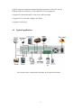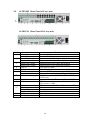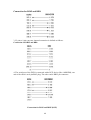
1
The Alien Pro Digital Video Recorder
Operations Manual
ALIEN504
Models
ALIEN508 ALIEN516
Networkable and Mobile
Phone monitoring
Version 8.21
Index
Safety Precautions .............................................................................................. 5
Chapter 1 Product Introduction.........................................................… ...
1.1 Summary ......................................................................................................
1.2 Model Description ......................................................................................
1.3 Features .......................................................................................................
1.4 Typical Application .....................................................................................
Chapter 2 Installation ......................................................................................
2.1 Check DVR and its Accessories .................................................................
2.2 HDD Installation .........................................................................................
2.3 ALIEN504 Rear Panel of 4 way unit............................................................
2.4 ALIEN508/ALIEN516 Rear Panel of 8/16 units..........................................
2.5 External Alarm In/Out Connection .............................................................
Chapter 3 Operational Instructions ........................................................
3.1 DVR Front Panel .........................................................................................
3.2 IR Control ....................................................................................................
3.3 OSD Menu Description ...............................................................................
3.3.1 Main Menu Items ....................................................................
3.3.2 Navigating Menus ...................................................................
3.3.3 Menu Operation ......................................................................
3.4 Character Input ...........................................................................................
6
6
6
7
9
10
10
10
13
14
15
16
16
17
19
19
20
23
24
Chapter 4 Basic Operation Guide ...........................................................
25
4.1 Power on ....................................................................................................
4.2 Live View ..................................................................................................
4.3 Login ..........................................................................................................
4.4 PTZ Control ...............................................................................................
4.5 Manual Record ..........................................................................................
4.6 Playback ....................................................................................................
4.7 Backup Recorded Files .............................................................................
4.8 Powering Down the DVR .........................................................................
25
25
26
27
28
29
31
32
Chapter 5 Main and Spot Monitor Output .......................................
5.1 Main and Spot Output ................................................................................
5.2 Main and Spot Monitor Output Live View ................................................
5.3 Main and Spot Monitor Playback ...............................................................
5.4 Main and Spot Monitor Output to Control PTZ .........................................
2
34
34
34
35
35
Chapter 6 Advanced Operation Guide .................................................
36
6.1 User Management ......................................................................................
6.1.1 Add Users ..............................................................................
6.1.2 Delete User .............................................................................
6.1.3 Password Modification ..........................................................
6.1.4 User Rights ............................................................................
6.2 Device ID ...................................................................................................
6.3 Video Standard and VGA Setup ................................................................
6.4 Date and Time Setup ..................................................................................
6.4.1 Daylight Saving Time Setup ..................................................
6.5 Image Setup ................................................................................................
6.5.1 Camera Name Setup ...............................................................
6.5.2 Video Parameter Setup ...........................................................
6.6 Mask Area Setup (Privacy Mask) ..............................................................
6.7 View Tampering Alarm ..............................................................................
6.8 Video Loss Alarm ......................................................................................
6.9 Motion Detection Alarm ............................................................................
6.10 Live View Setup .......................................................................................
6.11 Recording Setup .......................................................................................
6.12 Alarm I/O Setup .......................................................................................
6.13 Network Setup ..........................................................................................
6.13.1 Network Settings ..................................................................
6.14 PTZ Setup ................................................................................................
6.14.1 PTZ RS485 Connection .......................................................
6.14.2 PTZ Settings ........................................................................
6.14.3 PTZ Control .........................................................................
6.14.4 Preset Setup .........................................................................
6.14.5 Sequence (Tour) Setup ........................................................
6.14.6 Cruise (Pattern) Setup: .........................................................
36
37
37
37
38
39
40
40
41
42
42
42
43
44
45
46
49
49
52
55
55
57
57
57
58
58
58
59
Chapter 7 Utilities ...............................................................................................
60
7.1 Default Parameters ....................................................................................
7.2 Hard Disk Management .............................................................................
7.3 Alarm Outputs ......................................................................................… .
7.4 Reboot ........................................................................................................
7.5 Power Off ...................................................................................................
7.6 View Log ....................................................................................................
7.7 System Information ....................................................................................
60
60
61
61
61
61
62
Chapter 8 Firmware Upgrade ....................................................................
63
3
Appendix A HDD Capacity Calculation ..............................................
64
Appendix B DVR Connector Definition ...........................................
65
Appendix C Specifications ...........................................................................
69
Appendix D Quick Search Manual Guide .....................................
70
Appendix E Days Recording per HDD for ALIEN504...............
71
Appendix F Days Recording per HDD for ALIEN508 ..............
72
Appendix G Days Recording per HDD for ALIEN516 ...............
73
4
Safety Precautions
Caution:
To reduce the risk of electric shock, please do not remove the cover without powering down.
There are no user-serviceable parts inside.
Important Safeguards:
1.
2.
3.
4.
5.
6.
7.
8.
9.
10.
11.
Please read these instructions before use.
Do not use this apparatus near water.
Clean only with a dry cloth.
Do not block any ventilation openings. Install in accordance with the manufacturer's
instructions.
Do not install near any heat sources such as radiators, ovens or other apparatus that
produces heat.
Ensure that the DVR is powered correctly and that the power cord plug is not damaged.
Only use attachments/accessories specified by the manufacturer.
Ensure the DVR is not subjected to shock or vibration.
Unplug this unit during lightning storms or when unused for long periods of time.
Always disconnect the power before moving the unit.
To reduce the risk of fire or electric shock, this apparatus should not be exposed to
rain or moisture.
Cleaning:
You can clean the unit with a moist lint-free cloth or chamois leather cloth.
Unpacking:
Check the package for visible damage. If any items appear to have been damaged in
shipment, notify the supplier immediately. Unpack carefully. This is electronic equipment and
should be handled with care to prevent damage to the unit. Do not attempt to use the unit
if any components are damaged. Notify any missing items. The shipping carton is the safest
container in which to transport the unit. Save it and all packing materials for future use. If the unit
must be returned, use the original packing if possible.
Packaging contents:
The package should contain the following items:
1.
Digital Video Recorder
2.
Accessories box
5
Chapter 1
Product Introduction
1.1 Summary
The Alien Pro series Network Digital video Recorders are excellent digital
surveillance products. They adopt an embedded MCU (Microprocessor Control Unit)
and an embedded Real-Time Operating System (RTOS). They combine the most
advanced technology in the Information Industry such as video and audio
encoding/decoding, hard disk recording and TCP/IP transmission. The firmware is
burnt onto a flash memory, which makes it more stable and reliable than software
programs that run from a standard disk drive.
The Alien Pro series combine features of both Digital Video Recorder (DVR) and
Digital Video Server (DVS). They are widely used as stand-alone units or part of a
powerful surveillance system.
1.2 Model Description
The Alien Pro Digital Video Recorder is produced in three models.
The ALIEN504 is a four way input channel recorder.
The ALIEN508 is an eight way input channel recorder.
The ALIEN516 is a sixteen way input channel recorder.
6
1.3 Features
Compression:
•Supports up to 16 video channels (NTSC/PAL). Each channel is independent,
H.264 hardware compression and real-time (NTSC 30FPS, PAL 25FPS).
Supports both variable bit rate and variable frame rate.
•Supports up to 16 channels audio input channels. Each channel is independent
OggVorbis compression and the bit rate is 16Kbps.
•Compressed video and audio are synchronous. You can select either mixed
stream (video and audio) or video only.
•Supports 4CIF, DCIF, 2CIF, CIF and QCIF resolution.
•Supports multi area motion detection.
•Supports OSD and changeable OSD position.
•Supports LOGO and changeable LOGO position.
Local functions:
Record:
•Supports multiple record methods including real-time, manual record, motion
detection, external alarm, motion&alarm and motion|alarm.
•Supports up to 8 HDDs. Each HDD can support 2000GB maximum.
•Supports FAT32 file system.
•Supports HDD S.M.A.R.T technology.
•Supports continuous (overwrite) and linear (stop when full) record modes.
•Supports backup of recorded files and video/audio clips. Supports USB memory
stick, USB HDD, USB CD-R/W, USB DVD-R/W and SATA HDD for backup.
Preview and playback:
•Supports BNC analog monitor and VGA output for main output.
•Supports one spot video and spot audio output.
•Supports multiple live view modes.
7
•Supports Privacy Mask (blanks portions of camera view).
•Supports camera block alarm.
•Supports mult-synchronous playback. Support play forward, backward, pause,
frame by frame, etc.
•Supports play back by files or by time/date.
•Displays local record status.
PTZ:
•Supports multiple PTZ protocols.
•Supports preset, sequence and pattern.
Alarms:
•Supports exception alarm, motion detection alarm, external alarm, etc.
Miscellaneous:
•Supports IR Remote control.
•Supports RS-485 keyboard.
•Support multi-level user management.
Network:
•Supports TCP, UDP, RTP, Multicast for network viewing.
•Support PPPoE for broadband dial-up. Note that this is not supported.
•Support DDNS, E-mail and NTP.
•Supports PSTN for standard dial-up.
•Supports remote parameter setup.
•Alarm information can be sent to remote center.
•Network controlled PTZ.
•Network recording of video/audio.
•Network download and playback of recorded files from the DVR.
•Remote upgrade of DVR firmware.
8
•RS232 supports transparent channel function so that the remote PC can use
DVR to control serial devices. Note that RS232 is not supported.
•Supports bi-directional audio or one-way audio broadcast.
•Supports IE to view and configure the DVR.
•Supports activity log.
1.4 Typical Application
Note that the above functionality depends on the model purchased.
9
Chapter 2 Installation
2.1 Check DVR and its Accessories
Please check the contents of the shipping container. If any of the items are missing
please contact your supplier.
2.2 HDD Installation
If you have not purchased Hard Drives for this DVR you can calculate the total
capacity you need (refer to Appendix A).
Installing the hard disks should be performed by a qualified person. When working
with electrostatic sensitive devices such as a hard disk or the DVR unit, make sure
you use a static-free workstation. Any electrostatic energy coming in contact with the
hard disk or DVR main board can damage it permanently.
Installing SATA HDD
1. Before installation of the HDD, switch the recorder off and unplug the power cable.
2. Place the recorder on a flat table, and make sure you take proper ESD precautions.
Wear an ESD bracelet at all times. A Philips screwdriver is required to disassemble
and reassemble the unit.
3. Remove the metal top cover by removing two screws from the rear of the cover,
slide the cover towards the rear and lift it from the unit.
4. Remove the metal hard drive brackets (remove one screw from the top of the
mounting plate, lift the rear of the plate and slide backwards).
To remove the bottom plate, remove the mounting screws that are inserted from the
outside of the unit (one on each side).
Make sure that the hard disk bracket does not come into contact with the PCB, as this
could cause damage.
10
5. Place the hard disks you wish to install on a table with the mounting side facing
upwards.
6. Place the metal hard disk bracket on top of the hard disks, and fasten each hard disk
with 4 screws to the bracket.
7. Reinstall the bracket and then connect the power and data cables to the HDD and
main board.
11
8. Check all connections, and reinstall the metal cover on the DVR.
9. Connect the power cable and power on the DVR.
10. Press [MENU] key to enter into
DVR main menu. Go to the "Utilities"
menu and choose "Hard disk" to format
the hard disks. Check that all installed
disks are detected by the DVR (shown in
the menu). Choose "Format" and select
"All" to format all hard disks. When all
drives are formatted a confirmation
message will be shown on the screen.
Ensure that all installed disks have the
status "OK".
12
2.3 ALIEN504 Rear Panel of 4 way unit
Number
Interface
1
Video Input
Audio Input
2
Description
Standard BNC
Standard BNC
Main Video Output
Main Audio Output
Connect CCTV monitor, output video and menu
Local Audio Output
3
Line In
USB Interface
Audio line input for voice talk
USB Memory stick, USD HDD, USB CD/DVD
or USB mouse
4
VGA Interface
VGA Display
5
RS232
Network Interface
Connect RS232 devices. See Appendix B.
Connect Network devices. See Appendix B.
SW1
6
RS485
Alarm Input
Relay Output
RS485 terminal resistor switch. Default is Off.
The resistor is 120 .
PTZ Connection. Use T+ and T- to connect PTZ.
4 sensor alarm in.
2 relay outputs.
7
GND
Ground
8
AC Input
100 ~ 240 v AC
9
E-SATA
Optional. Extends 1st internal SATA to ESATA.
13
2.4
ALIEN508 Rear Panel of 8 way unit
ALIEN516 Rear Panel of 16 way unit
Interface
Number
1
Video Input
Audio Input
2
Spot Video Output
Spot Audio Output
3
Main Video Output
Main Audio Output
4
Line In
5
VGA Interface
6
RS232
Network Interface
7
USB Interface
8
9
10
11
12
E-SATA
SW1
RS485
Alarm Input
Relay Output
Keyboard Interface
GND
AC Input
Description
Standard BNC
Standard BNC
Spot monitor for live video and playback
Spot monitor for live audio and playback
Main monitor for live video and playback
Main monitor for live audio and playback
Line input for audio
VGA Display
Connect RS232 devices. See Appendix B.
Connect Network devices. See Appendix B.
USB Memory stick, USD HDD, USB CD/DVD or
USB mouse
Optional. Extends 1st internal SATA to E-SATA.
RS485 terminal resistor switch. Default is Off.
The resistor is 120 .
PTZ Connection. Use T+ and T- to connect PTZ.
16 sensor alarm in.
4 relay outputs.
Use D+/D- for keyboard.
Ground
100 ~ 240 v AC
14
2.5 External Alarm In/Out Connection
Alarm input dry contact:
Alarm input port (dry contact):
G (GND): Connect the GND of
sensor.
1~8: Alarm input, support normally
open/normally closed.
0: Reserved.
Alarm output:
1G ~ 4G: 4 relay output.
Alarm output connection:
Powering Up:
Note: Complete all cable connections before powering on the DVR.
1. Switch on all connected equipment.
2. Connect the power cable to the unit.
3. Switch on the power supply power switch.
15
Chapter 3 Operational Instructions
3.1 DVR Front Panel
2
1
4
7
5
3
6
Number
1
Type
Name
1 ~ 16
2
Camera
Indicator
Lamps
3
Power
Power
4
Status Lamps
5
Input Keys
Description
Infra Red receiver
Ready
Status
Alarm
Modem
HDD
Link
Tx/Rx
Numeric Keys
F1
F2
Menu
ESC
Play
6
Function Keys
REC
Edit
PTZ
A
16
Shows 1 ~ 16 camera status. Green means
recording; Red means network transmission;
Orange means recording and network
transmission.
Device switch with power indicator light. Green
means DVR is operating; Red means DVR is
powered Off; No light means no power
connected.
DVR is ready
Green means you can use IR remote
Red means there is an alarm
Green means there is a modem connection
Flickering red means reading/writing to HDD
Green means there is a network connection
Flickering Green means data is being transmitted
Input numbers, lower case, uppercase and
symbols
[Light] in PTZ control
[AUX] in PTZ control
1. Enter Menu (from Live mode)
2. Wiper control in PTZ mode
3. Press and hold [MENU] for 5 secends to
cancel key-down tone
Cancel and return to previous menu
1. Local playback
2. [AUTO] in PTZ control
1. Manual record
2. Preset in PTZ mode
1. In edit mode, delete current character
2. [IRIS+] in PTZ mode
3. Select üor x to enable or disable
1. Enter into PTZ control mode
2. [IRIS-] in PTZ mode
1. Input character
2. [FOCUS] in PTZ mode
3. Display or hide the channel status
1. Multi Screen selection
2. Switch menu mode into live view
3. [FOCUS-] in PTZ mode
[ZOOM+] in PTZ mode
1. Switch main/spot video output control mode
2. [ZOOM-] in PTZ control
PREV
6
7
Function Keys
Control Keys
INFO
Main/Aux
Direction Keys
Composed of up, down, left and right arrow.
1. Menu mode. Use direction keys to select, press
[Enter] or [Edit] key to edit.
2. PTZ direction control.
3. Playback speed control.
1. Menu confirmation
2. Select ü or x to enable or disable
3. Pause playback
Enter
3.2 IR Control
17
Loading the batteries into the IR controller:
1. Remove the battery cover.
2. Insert the battery. Ensure that the poles (+ and -) are correctly positioned.
3. Replace the battery cover.
Enable the IR Remote Controller:
1. Press the [DEV] key, input the DVR device ID (default is “88”. It can be changed
in the “Display”menu) and then press the [ENTER] key.
2. The “STATUS”lamp on the DVR front panel will turn green, indicating that you
can use IR controller to operate the DVR.
Disable the IR controller:
1. When IR controller status lamp is on, press the [DEV] key.
2. The “STATUS”lamp on the DVR will turn off. The IR controller won’t control the
DVR.
Turn off the DVR:
1. When IR controller status is on, press the [POWER] key for several seconds.
2. The DVR will be powered off.
Troubleshooting the IR Remote:
1. Always aim the IR Remote controller at the DVR you want to control.
2. Make sure that the correct DVR ID code is entered and the status lamp on the
DVR is green.
3. Check the batteries.
4. Make sure nothing is obstructing the IR sensor on the DVR.
5. Try another IR Remote control.
Note: If you have only one Remote unit to work with it is often difficult to verify whether the unit
is actually working. Humans can’t see the IR LED flashing on the remote when keys are pressed.
Cameras can see the LED flash. Aim the Remote at a conveniently placed camera and you can see
the LED flash on the monitor.
18
3.3 OSD Menu Description
3.3.1 Main Menu Items
19
3.3.2 Navigating Menus
The Operation Manual provides step by step instructions in the early chapters. The
later chapters provide directions without indicating some of the individual key presses
because you will have learned the basics by then. This section provides a brief
overview of navigating through the menus using the control keys and by using the
mouse. With this information you will be able to quickly access most DVR functions.
See the detailed text for further information on particular features.
There are several methods to control the DVR.
•Front Panel Control.
•IR Remote Control.
•Mouse Control.
•Remote Software Control.
The details in the manual concentrate on the Front Panel control method. The IR
Remote control operation is essentially the same using the remote device. There are a
few differences that are mentioned in the manual. Mouse control is an option that can
be used, but is not mentioned throughout the manual. The remote software is
addressed in a separate manual.
Mouse Control: There are some things to consider when using a mouse with the
DVR. A USB mouse is used. There is one USB connection on the rear panel of the
DVR. A USB port expander may be used to add additional USB connectivity to the
DVR. This could be helpful in exporting files to a USB device and when updating the
firmware. Do not place a mouse pad on the top cover of the DVR as this may block the
access holes and cause air flow restriction and heat buildup that may cause damage
to the unit.
Most DVR operations can be performed using the mouse. If you are close enough to
the unit to use a mouse you will also be able to use the front panel and IR Remote
keys for operation. You will decide which operations are more easily performed with
each control method.
In Live View control:
Double click the left mouse key on an individual camera in a multi-screen
display to go to full screen. Double click again to return to the previous multi-screen
display. A right mouse click produces a display menu that provides access to a large
number of features.
•Main Menu: Provides access to the DVR Menu.
•Single: Allows selection of any full size camera display.
•Multi-Preview: Select “Live View”of 4, 9, 12, or 16 channel multi-screen
modes. (Depends on model used)
•Next Preview: Selects the next sequential display (ex. In four-channel mode: 1-4,
5-8, etc.). (Depends on model used)
•PTZ Control: Access PTZ camera control.
•Play: Enter playback mode.
•Manual Record: Access the Manual Record Menu.
•Close Status: (Open status): Show/hide the status line on the monitor.
20
•Switch VOUT: Switch to the “Spot”monitor output. (Depends on model purchased)
Caution: If you select “Switch VOUT”you will lose mouse control of the main monitor.
The mouse pointer will move to the Spot display. If you have a monitor connected to
the “Spot”output you can right click and select “Switch VOUT”to return to the main
display control. If no “Spot”monitor is available you will not be able to return to the
main output using the mouse. You must press the “Main/Aux”key on the front panel,
or the “VOIP/MON”key on the IR Remote. The same issue is present when using
front panel and IR Remote operation. If the Spot monitor is inadvertently selected (by
pressing the appropriate key) when there is no Spot monitor installed, it will appear as
if the unit is not operating properly.
General Mouse Menu Navigation: A standard left mouse click will select most
options. Just position the mouse over the desired menu item and select. A “right
mouse click”displays an option list (from the live display). Once in the menu, a right
click will take you to the previous menu. Walk through the following list of items to
familiarise yourself with mouse operation.
Starting from the live display:
“Right-click”the mouse to view the control options and then and select “Main
Menu.”You can click on any of the options to enter sub menus. Click to select the Display Menu
and view the available options. Additional mouse clicks will select any menu option and/or
change the status of the check boxes. Select the “Setup”button next to time/date. You are now in a
“Sub, Sub menu.” Click on the ”Day”window next to “Date.”The display box allows you to
change the number entry. Just click on the numbers you want (don’t forget leading zeros).
Always remember to navigate to the “Confirm”button and press “Enter”to update your
selections. Otherwise the selections will not be updated.
A “right click”will take you back to the previous menu; first to the “Display”menu,
another “Right click”to the Main Menu and another takes you back to the live
display. There are some situations where mouse operation may seem erratic (especially if you use
the scroll button) but a little practice can make this a preferred method for controlling the
DVR.
Control from the Front Panel Keys:
Front Panel: All DVR functions are controllable from the front panel keys. Reaching the
front panel may be difficult in some installations so the IR Remote is a good alternative
when the DVR is in sight, but not in reach.
Function Keys:
•MENU: Enter the DVR Menu.
•ESC: The escape key returns to Live mode, or to a previous menu.
•PLAY: Enters Playback.
•REC: Enters Manual Record Menu.
•EDIT: Selects the next sequential display (ex. In four-channel mode: 1-4, 5-8, etc.)
in Live Mode. Change selections in Menu Mode.
•PTZ: Enter camera control mode. (All function buttons are used for PTZ
functions when in PTZ Mode. See the red titling under each key for its PTZ
function). Press “ESC”to exit PTZ mode and restore normal function key
operation.
•A: Show/hide the status line on the monitor in Live Mode. Scroll through
character entry options in Menu Mode.
•PREV: Toggle “Live View”of 1, 4, 9, 12, or 16 channel multi-screen modes.
•MAIN/AUX: Toggle between Main monitor and Spot monitor control modes.
General Front Panel Key Menu Navigation: Press the “Menu”key to enter the Main
Menu. Moving the Active Window (highlighted cursor) is done by pressing the
direction keys (Up, Down, Left, Right) and item selection is done with the “Enter”
(center of arrow keys) key (or the EDIT key). Once in the menu, “ESC”will take you to
21
the previous menu and back to live mode. Walk through the following list of items to
familiarise yourself with key operation. Starting from the live display:
•Press the “Menu”key to enter the “Main Menu.”
•Use the Up/Down arrow keys to enter sub menus.
•Select the Display Menu to view the available options.
•Use the arrow keys to move to selected menu options and press “Enter”to select.
Enter (or, Edit) will also change check box selections.
•Select the “Setup”button next to time/date. You are now in a “Sub, Sub menu.”
•Select the ”Day”window next to “Date”(arrow keys, then Enter). Use the number
keys to enter your numerical selections and press “Enter.”
Always remember to navigate to the “Confirm”button and press “Enter”to update
your selections. Otherwise the selections will not be updated.
Press “ESC”to take you back to the previous menu; first to the “Display”menu,
“ESC”again to the Main Menu and again to return to the live display.
22
3.3.3 Menu Operation
How to access the menus:
•Press the [MENU] key to enter the DVR main menu
•Press the [PLAY] key to enter the playback menu
•Press the [REC] key to enter the manual record menu
•Press the [PTZ] key to enter the PTZ control interface
Note: You must input a valid user name and password. The default user name is
“admin”and password is “12345”.
Main Menu Description:
Main menu:
One section of the menu screen will be highlighted to indicate the input cursor
position. The Active window can be moved from one item to another by using the
direction keys ([ ] [ ] [ à ] [ ß ]). When the “Active Window”is located on an item,
you can press the [ENTER] key to enter into the sub menu. For example: Move the
“Active Window”to “Image”and then press [ENTER] to enter into the secondary
menu as follows:
23
1. Check Box: Provide 2 options. “ ”means enable and “× ”means disable.
Select either [ENTER] or [EDIT] to change selections.
2. List Box: Provides more than 2 options. However, only one of them can be
selected. You can press [ENTER] or [EDIT] to enter into edit mode, then use
[ ] and [ ] to select one option. For example, on the right side of “Select
Camera”, there is a list box for you to select one camera.
3. Edit Box: Allows you to input characters. Press the [EDIT] key to enter the
edit mode. You can input characters as follows:
(1) Press the [A] key to select the entry mode (numbers, upper case, lower
case or symbols).
(2) Use [
à
] and [ ß ] keys to move the cursor.
(3) Use the [EDIT] key to delete the character in front of the cursor.
(4) Press [ENTER] or [ESC] to exit the edit mode.
4. Button: Execute a special function or enter into the next sub-menu. For
example, press the “Policy”button to enter into sub-menu. Press [Confirm]
to save parameters and return to the previous menu. Press the [Cancel] key
to cancel and return to previous menu. Grayed-out buttons indicate they can
be operated only after another selection is enabled.
Exiting the Menu: Press [ESC] to exit the menu and return to live view mode.
3.4 Character Input
There is a status line at the bottom of all character entry screens. For example: In the
“camera name”edit box the following status line appears at the bottom of screen.
The word ”Number”indicates that you can use the numeric keys to input numbers.
Press the [A] key to change input modes. Available options are “Number”, “Uppercase”,
“Lowercase”and “Symbol”.
Uppercase
Lowercase
Symbol
There are 24 symbols in all. They are divided into 4 pages. Press the [0] key to scroll
through the available selections.
Note: The character input scheme may seem difficult until you become familiar with its
operation. All setup procedures may be accomplished from the remote software using a
more familiar Windows format.
24
Chapter4 Basic Operation Guide
4.1 Power on
Note: It is always a good idea to check the power supply before connecting the AC
cable and applying power. The DVR is equipped with a universal power supply that will
accommodate 120/240VAC, 50/60Hz. Units with an input power selector switch must be
placed in the correct input voltage position for the local area before applying power.
Switch the main power switch off before inserting the AC power cord. Connect a monitor
(VGA, or composite) to view the GUI and setup the unit.
If the [POWER] lamp is off, please do as follows:
1. Make sure the power cord is connected to an active power source.
2. Switch on the power key on the real panel.
If the [POWER] lamp is red:
1. Press the [POWER] key to start the DVR.
2. The power lamp will turn green as the unit powers up.
3. The DSP and HDD initialisation process will be shown on the monitor.
The graphics include two lines. The first line indicates the DSP hardware and the
second lists the available drives installed. A check mark ( ) indicates correct
operation of the DSP and the presence of a disk drive installed in one of the eight
available drive locations. An “X”indicates improper operation or an uninstalled
drive.
Note: If no drives are installed or detected, a “No Disk”message will display.
4.2 Live View
At startup, the DVR will enter the live view mode. On the live display you will see the
date/time, camera name and camera/alarm status line in addition to the video from
attached (and configured) cameras. The information in the status line is described later in
this manual. You can easily toggle the status line on/off by right clicking the mouse and
selecting “Show”or “Close”status, or press the “A”key on the DVR front panel or IR
Remote.
On the live screen, you will see date, time, camera names and camera status icons.
Note: To set the system date and time in “Display”menu, refer to section 6.4.
To change camera names in the “Image”menu, refer to section 6.5.
See the following chart for camera record status indications:
Icon
Colour
White
Yellow
Pink
Green
Blue
Red
Action
No video signal
Video input
Manual recording
Continuous recording
Motion detect recording
External alarm recording
See the following chart for alarm status indications:
25
Icon
Colour
White
Yellow
Pink
Green
Blue
Red
Action
Video signal lost
View tampering alarm
Motion and External alarm
No alarm
Motion alarm
External alarm
Press the numeric keys to switch to an individual camera in live view. If the DVR has less
than 10 channels, press one numeric key to switch to the corresponding channel. For
example: Press [2] to view camera #2.
If the DVR has 10 or more 10 channels, press two numeric keys to switch to the
corresponding channel. For example: Press [0] [2] to select camera #2.
Press [1] [2] to select camera #12.
Press the [EDIT] key to manually sequence live views. You can set auto preview mode in the
menu (refer to section 5.2).
Press the [PREV] key to switch multi-screen views.
Press the [Enter] key to pause/resume sequence live view.
4.3 Login
Note: The DVR factory default user name and password is “admin”“12345”.
“admin”is the administrator which allows access to all of the DVR functions. It cannot be
renamed. The administrator can create up to 15 individual users and apply individual privileges to
each. Press the Menu key and the Login dialog appears.
1. Use the [ á ] / [ â ] keys to select a user.
2. Press the [ à ] key to enter the “Password”edit box. Input the corresponding
password. Press [ENTER] to exit edit box. The “Active Window”will move to the
“Confirm”button.
26
3. Press [ENTER] to confirm the entry.
Note: An incorrect user name/password entry will result in an audible alarm. After three
incorrect entries the DVR will switch to the live display mode.
4.4 PTZ Control
Note: Ensure that PTZ communication parameters have been configured properly before
attempting normal operation. Your password must have PTZ control enabled in order to
control cameras. Note: Please refer to “PTZ Setup”in section 6.14.
Entering the PTZ control interface:
In live mode, press the [PTZ] key. In the login dialog, select a user name and input the
correct password. In menu mode, press the [PTZ] key and you will enter the PTZ control
interface directly.
There is a “PTZ Control”prompt in the PTZ control interface. The displayed camera name
indicates the camera under control. For example, “Camera 01”means you are controlling
PTZ camera #1.
Select the desired channel:
In the PTZ control mode, you can press the numeric keys to select the desired channel
(Ex: “0,””1,”for camera #1 –or “1”if using a 4/8 channel unit).
After you select the camera PTZ, you can use the shortcut keys to control the PTZ.
PTZ Control Options:
Direction control keys: [ ], [ ], [ ], [ ]
ZOOM control keys: [ZOOM+], [ZOOM-]
FOCUS control keys: [FOCUS+], [FOCUS-]
IRIS control keys: [IRIS+], [IRIS-]
Adjust preset keys: [REC/SHOT]
Auto control key: [PLAY/AUTO]
Wiper control key: [WIPER/MENU]
Light control key: [LIGHT/F1]
Auxiliary control key: [AUX/F2]
Calling Preset positions:
In the PTZ control mode, press the [REC/SHOT] key, and then enter the preset number
(three numeric keys). The camera will go to the corresponding preset position.
Setting Preset Positions:
To set a camera preset position, move the camera to the desired position. Press and hold
the [REC/SHOT] key while entering the preset number.
Note: A preset must be established before you will be able to call the preset in normal
operation. Refer to PTZ menu for preset setup.
When you exit PTZ control mode, the camera will stay at the current position (depending
on the dome used. Some domes may select a return to home position after a
predetermined time).
Start/Stop auto PTZ control mode:
In PTZ control mode, press the [PLAY/AUTO] key to start the PTZ auto function. Press the
[PLAY/AUTO] key again to stop.
Note: When PTZ is in auto mode it will stay in auto mode when you exit the PTZ mode.
You must enter into PTZ control mode again, and press the [PLAY/AUTO] key to stop.
Exit PTZ control mode:
Press [ESC] or [ENTER] to exit and return to the live view mode.
27
4.5 Manual Record
Note: In order to perform this function the DVR must have drives installed and formatted
and the user login password must have “Record”enabled. Manual record is lost after a reboot.
Manual record:
1. In the live view mode, press the [REC] key. In the display login dialog, select a
username and input the correct password to enter into the “Manual Record”
interface.
2. In menu mode, press [REC] to enter the “Manual Record”interface directly.
Manual Record Menu:
The Manual Record interface has the following selections: Channel number, channel
status, start/stop record, start all and stop all buttons.
1. Channel: Indicates available camera inputs.
2. Status: Indicates one of four settings:
means idle.
Green means the channel is recording (or set to record including: Continuous
recording, alarm recording, motion detection recording).
Red means network transmission.
Orange means both recording and network transmission.
3. Start/Stop: “ü ”means start recording corresponding channel. “×”means stop.
4. Start All: Press this button to start all channels recording.
5. Stop All: Press this button to stop all channels from recording. Note: Manual
recording will be lost after a reboot.
Exit manual record:
Press the [ESC] key to enter the live view mode. Press the [MENU] key to enter the
main menu. Press the [PLAY] key to enter playback menu. Press the [PTZ] key to
enter the PTZ control mode.
28
4.6 Playback
Note: The user must have “Playback”permission associated with the user name and
password in order to enter playback mode.
Playback interface:
In the live view mode, press the [PLAY] key. In the display login box, select a
username and input the correct password to enter the “Playback”interface.
In the menu mode, press the [PLAY] key to enter the “Playback”interface directly.
Playback Menu:
The Playback interface has the following
selections: Chan: Rec. Type, Time
selection, Search, Play, Select page, File
list box, Backup devices, Copy and
Backup Today.
1. Main Channel: Use the [ ] or [ ] key
to select one channel.
2. Second Channel: If the DVR
supports 2-ch playback, you can use the
[ ] or [ ]
keys to select the second channel (other than main channel). These two channels
can be played back synchronously. If you select the second channel as none, only the
main channel will playback.
3. Rec Type: Use [ ] or [ ] to select recorded files type. The file type options have
“All”, “All Time”, “Motion Detect”, “Alarm”and “Manual”.
4. Time Selection: You can define the search time section. Move “Active Frame”to
the time edit box and use numeric keys to input the time.
5. Search: Search the matched recorded files and display them in the list box. If
there is not matched file, a corresponding box will be displayed.
6. Play by Time: Playback the recorded stream directly based on the time section.
7. Select Page: In the file list box, each page will only display 8 files. If the matched
files are more than 8, you can select page to list other files. 500 pages (4000 files)
can be searched at one time. You can use numeric keys or [ ] [ ] keys to select
page.
8. File List Box: List the matched files. File start time and file size are displayed in
the list box. You can use [ ] [ ] keys to move the scroll bar to select file.
9. Backup Devices: You can select USB flash, USB HDD, USB CD/DVD or SATA
CD/DVD to backup the files or clips.
29
10. Copy: Start backup.
11. Backup Today: Backup all recorded files created today.
12. Coding Format: You can select either an H264 backup or AVI backup.
13. Backup: Use this backup option for option 12 backup.
There are two playback modes:
1. Search and playback a file: In the playback menu select a channel to search,
and a record type. Move the “Active Window”to the “Search”button and press
[ENTER]. The DVR will search and list the matched files.
2. Playback by Time: In the playback interface, select a start and an end time using
the time entry boxes and then select the ”Play”button. Video playback will start
from the start time selected. If there are more than eight matched files, use “Page No.”
to select additional pages (use numeric keys or [ ] [ ] keys to select a page). In the
file list box, use the [ ] [ ] keys to move the scroll bar to the desired file and press
[ENTER] to playback the file. If a
second channel is selected, these two
channels can playback synchronously.
Note: If no file match is found, a
message will displayed indicating that no
matching
files were found.
There is an information bar at the bottom
of the display with the following
information: Volume, Play Progress,
Play Speed, Played Time and File Total
Time.
The following front panel playback controls are available:
1. Display/Hide information bar: [MENU]
2. Open/Close sound: [PLAY]
3. Adjust play progress: [
] (Backward), [
] (Forward). The unit is “%”.
4. Adjust play speed: Normal speed is “1x”. Use [ ] to increase play speed (2X, 4X,
8X and MAX). Use [ ] to decrease play speed (1/2X, 1/4X, 1/8X and Single
Frame). When in “Single”frame pressing [ENTER] moves forward one image at a
time (single step).
5. Pause/Continue: Press [ENTER] to pause/continue playback.
30
6. Copy segment: [EDIT] to start copy, [EDIT] again to end copy.
7. Exit: [ESC]
8. Playback switch: When in 2-ch playback, press [PREV] to switch between main
channel and second channel.
Note: When the DVR is performing multiple tasks the actual play speed may not
match the speed selected.
Exit playback:
1. From the playback interface, press [ESC] to return to the Live mode.
2. From the playback interface, press [MENU] to enter into main menu.
3. Press [REC] to enter the manual record menu.
4. Press [PTZ] to enter the PTZ control mode.
4.7 Backup Recorded Files
Note: The user must have “Playback”permission associated with the username and
password in order to enter playback mode and back-up files.
Some applications require data to be saved for a long period of time. The required
information could range from a short video clip up to the entire database. This section
addresses ways to export video from the DVR.
Back up selected files:
1. From the “live”mode, press [PLAY].
2. Enter a valid user name and password to enter the Play Back Menu.
3. Search files as indicated in section 4.6.
4. Select a file in the file list box.
5. Select the “Save Device”(USB flash memory, USB HDD, USB CD/DVD, SATA
CD/DVD or SATA HDD).
6. Select “Copy.”A display box will indicate that the file copy is in progress and
when the file copy is completed.
Backup a days recorded files:
1. In the playback interface, select the “Backup Today”button and press [ENTER].
2. All intraday recorded files from all channels will be saved to the device selected.
Ensure that the backup device has sufficient space to store the data selected. A
dialogue will display the backup status.
31
Note: If backup device is not connected
correctly, or the DVR does not detect the
backup device, a “Device Error”
message will displayed.
Backup video clips:
You can back-up video clips as the file is being
played back. The steps are:
1. Search for and select the video you want to
export.
2. Play the video and press [EDIT] to start saving the clip.
3. Press [EDIT] again to mark the end of the clip. This clip is ready for export.
4. Repeat the steps above to select additional clips (up to 30 total).
5. Press [ESC] and a message window will display indicating the number of files to
be copied.
6. Select “Confirm”and the backup will begin. (“Cancel”will abort the process).
Press “Confirm”again at the “File Copied”message.
Note: The backup function is effective when two channels are played back
synchronously. In such case, each channel can backup 30 segments so 60 segments
can be backed up for two channels.
Playback backup video files:
You can playback recorded files in any PC using File Player software. File Player
software is available on the CD supplied with the DVR. You have a choice of format
on CDRW.
4.8 Powering Down the DVR
Note: Turning off the power switch on the rear panel, or pulling the power cord from
the unit is not recommended in order to avoid corrupting data on the disk drives. The
safest method is to enter the Menu and turn off the power using the Utilities Menu.
Alternately you can press and hold the front panel Power key (or, the IR Remote
Power key) for five seconds.
32
Shutting down the DVR using the menu:
1. Enter the “Utilities”menu. (Main, Utilities).
2. Move the “Active Window”to “Power Off”and press ENTER.
3. In the power off menu, press “Confirm”to shut down the DVR.
4. Enter a user name and password as required.
Power off using the [POWER] key on
the front panel or IR Remote:
1. In the “Live”mode press and hold the
[POWER] key (on the front panel or IR
Remote) for more five seconds.
2. A power off display will ask you to
confirm your selection.
3. Enter a user name and password as
required. If an incorrect password is
entered
three times the unit will return to the live
view mode.
Note: A message will display indicating “Power Off in Process.”Do not press any
additional keys while the shutdown is taking place.
Abnormal Shutdown:
Warning: Do not power off the unit by switching off the power supply power
switch or by pulling the power plug.
Removing the power unexpectedly while the DVR is accessing the disk drives will
cause damage to the data and possibly to the drive.
Note: Maintaining constant regulated power to the DVR is essential for normal
operation and to preserve the data stored on the disk drives. A UPS (Uninterruptible
Power Supply) is recommended for all installations and essential in mission critical
applications.
33
Chapter 5 Main and Spot Monitor Output
5.1 Main and Spot Monitor Output
The DVR has one main video output and one spot output. The main video output
provides access to the DVR menu. The spot output does not. It is intended for normal
operation, not system setup. The spot output is an additional composite monitor used
for viewing live video, playback video and for local PTZ control.
Accessing the Main and Spot monitor
outputs:
1. Front Panel: Press the [Main/Aux] key to
toggle between the “Main”output and
the “Spot”output control mode.
2. IR Remote: Press the [VOIP/MON] key to
toggle between the “Main”output and
the “Spot”output control mode.
Note: Several functions are not available in
the “Spot”mode. If you can’t perform a
function, ensure that you are in the “Main”monitor mode.
5.2 Main and Spot Monitor Output Live View
The “Main”output is typically used for
control of all DVR functions. It provides all
the same functionality as the VGA monitor
output. The [Main/Aux] key toggles between
the “Main”and “Spot”monitor output
control modes. Select the “Main”mode and
then press the [Menu] key to enter the DVR
menu. The main video output
will display the following DVR menu:
Enter the “Preview”menu:
Screen Setup Options:
1. Select Out: Use “Select Out”to select the
main or Spot monitor outputs:
2. Preview Mode (Live view mode): Use the
[ ] [ ] keys to select the desired
screen configuration for edit. The menu allows
you to select screen formats and
insert camera numbers as desired. The number
of available formats depends on
the number of camera inputs available (1, 4, 9,
34
12 and 16 displays are available in
16 channel units) See “Layout”below for setup details.
3. Switch Time: This control sets the sequence dwell time in the sequence mode.
Each sequencing view will remain on the screen for the amount of time selected.
Options include 5, 10, 20, 30 seconds, 1, 2, 5 minutes and never (sequence off).
For example: With a 16 channel DVR, if you select “4 Screen”mode and a “20
second switch time, the DVR display will change four camera displays every 20
seconds (1-4, 5-8, 9-12, and 13-16).
4. Audio preview: If you enable audio (“ü ”), when you view a single camera the
DVR will play the audio associated with that channel.
5. Display Delay: The sequence time in seconds.
6. Layout: The menu provides a window divided into sections. The window sections
correspond to the screen format selected (1, 4, 9, 12 and 16). Each individual
section represents one camera. You can move the “Active Window”to each
section. Use the camera selection bar to insert the appropriate camera in the
desired position. For example: Select the 16 camera mode (16- screen in the mode
selection). Move the “Active Window”to one of the segments and press the [Enter]
(or [EDIT]) key to enter into the “Edit”mode. Press numeric keys to input a camera
for that section of the multi-screen display (”0”“1”for camera #1 on 16 channel
units –“1”for camera #1 on units with less than ten channels). The camera
number will display in the window. You can arrange the display in any camera
order. If you press 0 or 00, the corresponding window will not display live video.
7. Save the setup selections: Select “Confirm”
to save the viewing configuration.
Press “Cancel”or [ESC] to abort.
5.3 Main and Spot Monitor Playback
Both the “Main”and “Spot”display can be used
to playback the recorded files on the DVR
HDD. Press the [Main/Aux] key to enter into “Main”or “Spot”control mode, and
press the [PLAY] key to enter into “Playback”menu.
5.4 Main and Spot Monitor Output to Control PTZ
Press the Main and the Spot output may be used to perform PTZ control.
1. Press the [Main/Aux] key to select the desired output.
2. Press the [PTZ] key to enter the PTZ control mode.
Note: The [Main/Aux] key is not active while in the PTZ mode. Press the [ESC] key to exit
PTZ control mode in order to change monitor control modes.
35
Chapter 6
Advanced Operation Guide
Only users that have “Parameters Setup”permissions assigned to their user name can
perform the operations in this section. When the following parameters are modified
and saved, you must reboot the DVR before the new parameters take effective.
Parameters mentioned earlier do not require a reboot.
•Any network parameters in “Network”menu
•Stream type, resolution and record schedule in “Recording”menu
•External alarm sensor type in “Alarms”menu
•View tampering alarm schedule in “Image”menu
•Video loss alarm schedule in “Image”menu
•Motion detection alarm schedule in “Image”menu
•External alarm schedule in “Alarms”menu
•Alarm output schedule in “Alarms”menu
•RS232 mode in “RS232”menu
•Change video output standard in “Display”menu
•Change PTZ parameters in “PTZ”menu
6.1 User Management
The Factory Default user name and password is
“admin”“12345.”The user name “admin”can’t
be changed. You can change the admin password
for security reasons. Move the “Active Window”
to “User”and press the [ENTER] key to enter the
“User Management”menu.
Note: The system administrator (admin login name) can manage the permissions
assigned to individual users. Up to 15 additional users may be selected. When logged
on as “admin”you can add users, delete users, modify passwords and select
individual permissions for each user.
36
6.1.1 Add Users
Additional users may be added by those with admin
rights:
1. Enter the “User Management”menu (select User from
the main menu).
2. In the “User Management”menu, select the “Add”
button and press [ENTER].
3. Input the new user name in the pop-up dialog and press
[ENTER] (up to 15 users can be added).
Setup the password for a new user:
1. After you add a new user, the password is null (no
password). You can skip this
step if you do not want to change the password.
2. Enter the desired password.
3. Verify the entry.
4. Select confirm.
6.1.2 Delete User
1. In the “User Management”interface use the [ á ] [ â ] keys to select a user, then
use [ à ] to move the “Active Window”to the “Del”
button and press [ENTER].
2. In the displayed confirmation box, press “Confirm”to
delete the selected user, or
press “Cancel”or [ESC] to abort deleting.
6.1.3 Password Modification
Admin rights are required to change passwords.
1. Enter the User Management menu:
2. Select a user name to edit in the user name list box. Use [ á ] [ â ] to select a user.
3. Press [à] to move the “Active Window”to password edit box and press [EDIT] to
enter the edit status.
4. Use the numeric keys to input the new password. A password can be up to 16
numbers.
5. Move the “Active Window”to “Verify password”and re-enter the password.
6. Select “Confirm”and press [ENTER]. This will activate the new password.
37
Note: If there is an error in entering or verifying the password an error message box
will appear. Denoting that the “Password Change Has Failed”.
In this case, press [ENTER] to return to the password edit box, and re-enter the new
password and verify again.
6.1.4 User Rights
Setup permissions for new users:
1. In the users list box of the “User
Management”menu, use the [ á ] [ â ]
keys to
select the user name, then use the [ à ] key
to move to the “Set Privileges”button
and press [ENTER].
Note: Operational rights are divided into
“Local Rights”and “Remote Rights”. You
can assign the necessary rights to the user.
1. Use the [ à ] [ ß ] keys to select items and press [ENTER] or [EDIT] to enable or
disable the item. “ü ”means the right is assigned to that user.
2. After assignment, press the “Confirm”button to save the settings, or “Cancel”to
abort.
User rights description:
Local Rights: Local rights are for local operation, such as the operation using front
panel, IR controller and RS-485 keyboard and PTZ control.
1. Record: Manual start/stop recording;
2. Playback: Local playback and backup the recorded files;
3. Parameters Setup: Local setup the DVR parameters;
4. Log: Local view of the DVR log;
5. Utilities: Locally upgrade firmware, format HDD, reboot DVR and shut down
DVR etc.
Remote Rights: Remote rights are similar to local rights, the exception being that you
can perform these functions from the remote software.
PTZ Control: Remote control PTZ:
1. Record: Remote manual start/stop recording
2. Playback: Remote playback, download of recorded files from DVR
3. Parameters Setup: Remote setup the DVR parameters
38
4. Log: Remote view of the DVR log
5. Utilities: Remote upgrade firmware, format HDD, reboot DVR and shut down
DVR etc.
6. Audio: Client talks with DVR
7. Live view: Network live view
8. Alarm: Remote control of DVR alarm output
9. Local Video Out: Remote imitation of front panel operation
10. Com Control: DVR RS-232 transparent channel function.
MAC address:
This MAC address is not the address of DVR. It is the MAC address of the PC that
will access the DVR. If the MAC address is set to all zeros the user may connect to
the DVR from any remote PC. If you setup this MAC address, only the PC with this
MAC address can access the DVR using that user name and password.
At PC end, in the DOS prompt, you can use the “ipconfig”command to see the PC
MAC address.
6.2 Device ID
The device ID is a unique identifier for
the DVR. When you use an IR Remote
controller to operate DVR, you must use
this device ID to select the DVR. The
default device ID is “88”. If there is
more than one DVR in one place, define
a different device ID for each DVR.
Otherwise, the IR controller will control
all DVRs with the same device ID at the
same time.
1. In “Display”menu, select the device ID edit box.
2. Use the numeric keys to input a new device ID. The device ID value is ranged
from 01-255.
3. Press the “Confirm”button to save the new ID, or “Cancel”to abort.
39
6.3 Video Standard and VGA
Setup
Video standard: Changing the video
format (NTSC/PAL) is easily performed
in the
Display menu.
1. Select the “Display Menu from the
Main Menu.
2. Select the “Video Standard”button
and select the appropriate standard for
your area (NTSC/PAL).
VGA setup:
You can define the VGA resolution and refresh frequency in the “Display”menu.
Options include: 1024*768/60Hz, 800*600/60Hz and 800*600/75Hz.
1. Select the Display Menu.
2. Use the [ á ] [ â ] keys to select the desired format.
3. Press “Confirm”to save, or “Cancel”to abort.
6.4 Date and Time Setup
Setting the Date/Time:
1. Enter Display section.
2. Enter the date and the time in the appropriate boxes below DST Setup.
3. Enter section Setup next to DST.
4. Enable or disable the DST (Daylight Savings Time) option. If you enable DST you
must enter the change dates for your time zone.
40
5. Select “Confirm”to return to the previous menu.
Selecting the Date/Time Display Settings: You can modify the Time/Date display
properties for each camera, including display status, position and format. You can
copy the properties of one camera to all cameras. These modifications are made in the
“Image”Menu.
Selecting Camera Date/Time display settings:
1. Enter the “Image”Menu and select a camera to
modify.
2. Select the “Date OSD.”Options include:
Opaque&Steady, Transparent&Steady,
Transparent&Flashing, Opaque&Flashing,
No Display.
3. Select the “Position button next to the OSD setup. A display window will show the
position of the Time/Date display.
Display position and format: The image
consists of a 22x15 grid NTSC
(22x18 PAL). Use the [ â ] [ á ] [ à ] [ ß ]
keys to move the OSD position.
5. Press the [EDIT] key to select OSD time/date
format. Options include:
•MM-DD-YYYY day in week hh:mm:ss
(default)
•MM-DD-YYYY hh:mm:ss
•DD-MM-YYYY day in week hh:mm:ss
•DD-MM-YYYY hh:mm:ss
•YYYY-MM-DD day in week hh:mm:ss
•YYYY-MM-DD hh:mm:ss
YYYY = year, MM = month, DD = day, hh = hours, mm =
minutes and ss = seconds.
6. Press [ENTER] to save and return to the
“Image”menu or press [ESC] to abort.
6.4.1 Daylight Saving Time Setup
In the “Display”menu press the DST “Setup”button
to enter the DST setup interface.
DST means Daylight Saving Time. Select the check
box to enable the function, and enter
the DST start time and end time for you local area.
41
6.5 Image Setup
6.5.1 Camera Name Setup
Camera Name: You can modify camera names in the “Camera Input Adjustment”
Menu. Note: Camera names can’t be copied to other cameras.
1. From the “Main Menu,”select the
“Image”menu.
2. Select a camera to configure.
3. Select the “Name”entry to modify the
camera name. Move the “Active
Window”to the camera name edit box
and press [EDIT] to enter the edit mode.
You can input numbers, uppercase and
lowercase characters (refer to Chapter
3.4). The camera name can be up to 32
characters.
4. Press [ENTER] to exit the edit mode.
5. Select “Confirm”and press [ENTER] to save the modification, or Press “Cancel”
or [ESC] to abort.
Position the name on the display:
1. If you do not want to display the camera name, disable the check box beside
camera name edit box. The disable flag is “×”. If you enable the check box, you
can setup the camera name position. You can copy the position to any other
camera. The setup steps are:
2. Enable the check box on the right side of camera name, then move the “Active
Window”to the “Position”button and press [ENTER] to enter the camera name
position setup interface.
3. Use the [ â ] [ á ] [ à ] [ ß ] keys to move camera name position. Press
[ENTER] to return the “Image Setup”menu. Press “Confirm”to save the settings, or
“Cancel”or [ESC] to abort.
6.5.2 Video Parameter Setup
This feature allows you to make changes to the visual display of individual cameras.
You can adjust the brightness, saturation, contrast and hue. You can setup the camera
individually and can copy the video parameters of one camera to any other cameras.
Here are the setup steps:
1. Enter the “Camera Input Adjustment”menu and select camera (use the [ â ] [ á ]
keys to select a camera).
42
2. Select the “Adjust”button for each parameter; Brightness, Contrast, Saturation
and Hue. Press the [ENTER] key to access the parameter overlaid on an image of
the selected camera. Use the [ â ] [ á ] keys to adjust as you watch the image
change. When you are satisfied with the results, press [ENTER] to return “Image
Setup”menu.
3. Repeat the steps above to adjust any
other cameras.
4. Press “Confirm”to save the settings,
or “Cancel”or [ESC] to abort.
6.6 Mask Area Setup (Privacy Mask)
Some cameras may be installed in a sensitive area where it would be advantageous to
mask a portion of the image to prevent viewing and recording. A Privacy Mask can be
applied to any camera. This area will be blacked out on the viewed and recorded
image.
Setup of a Privacy Mask:
1. Enter the “Camera Input Adjustment”menu:
2. Select a camera: Use the [ â ] [ á ] keys to select a camera.
4. Enable the check box next to the “Area”button (press the Edit
key to enable “ü ”).
5. Select the “Area”button and press [ENTER] to enter the mask area setup.
Setup mask area: In the mask area setup interface, there is one small yellow pane on
the upper left side. For PAL cameras, the screen is divided into 22*18 sections. Use
the [ â ] [ á ] [ à ] [ ß ] keys to move the yellow pane to a starting position and
43
press the [EDIT] key. The yellow pane will turn red. Use the [ â ] [ á ] [ à ] [ ß ]
keys to extend the red privacy mask area.
•Note: Press the [A] key to clear all mask areas.
•The maximum mask area size is 8*8 panes. Up to four mask areas are allowed on
each camera.
•Once you have the area(s) defined, press [EDIT] to accept, or [ESC] to cancel.
Saving the masked area:
•In “Camera Input Adjustment”menu, press the “Confirm”button to save the mask
area, or press “Cancel”to abort.
•You can repeat steps listed above to setup mask areas for other cameras.
6.7 View Tampering Alarm
With this function enabled, an alarm will be produced when the camera view is
blocked.
1. Enter the “Camera Input Adjustment”menu.
2. Select a camera: Use [ â ] [ á ] keys to select a camera.
3. Reach the list dialog box next to “View Tampering”.
4. Sensitivity Selection: Use the [ â ] [ á ] keys to select the sensitivity level. The
sensitivity options are: Low, Normal and High. Selecting one of them will activate
the “Area Setup”and “Policy Setup”functions.
5. View tampering area setup: Move the “Active Window”to the “Area”button and
press [ENTER] to enter the area setup interface. The setup methods are the
same as those used for the mask area setup.
6. After setting up the area, press [ENTER] to return to the “Image Setup”menu, or
[ESC] to abort.
44
Note: Only one view tampering area can be setup per camera.
7. Alarm schedule setup: When there is a view tampering alarm present, the DVR
will handle the alarm based on the schedule selected. You can set 4 periods for each
day of the week. You can copy the schedule of one day to other days.
Note: Time periods must not overlap. You must reboot the DVR before the settings
take effect.
8. Setup alarm policy: If a view tampering alarm occurs while the schedule is active
the DVR will respond based on the policy Selected. You can select one or more of the
following: “On Screen Warning”, “Audible tone”, “Upload to Center”, “Trigger
Alarm Output”and “Send E-mail”. Use the [ â ] [ á ] and [EDIT] key to enable or
disable selections. “×”is disable and “ü ”is enable.
9. Save alarm setup: After selecting the setup parameters, press “Confirm”to
return “Camera Input Adjustment ”menu. In the “Camera Input Adjustment”menu
press “Confirm”to save the setup and return to the main menu, or “Cancel”or [Esc]
to abort.
10. Save all cameras: If you want to setup additional cameras, repeat steps two
through eight. In “Image Setup”menu, press “Confirm”to save all camera
parameters. Press “Cancel”key or [ESC] key to abort.
6.8 Video Loss Alarm
This feature provides an alarm when camera input video is lost.
1. Enter the “Camera Input Adjustment”
menu:
2. Select camera: Use [ â ] [ á ] keys to
select a camera and select “Advanced
settings”.
3. Select the “Handle”option next to
“Signal Loss.”
4. Setup alarm schedule: Enter “Policy”to setup alarm schedule. A video loss alarm
will be generated only during the scheduled times selected.
Note: The 4 time periods can be selected per day. The timeframes may not overlap.
The DVR must be rebooted before the settings take effect.
45
5. Setup alarm policy: You can select one or more response: “On Screen Warning”,
“Audible tone”, “Upload to Center”and “Trigger Alarm Output”. Use the [ â ] [ á ]
and [EDIT] key to enable or disable items. “×”is disable and “ü ”is enable.
6. Save alarm setup: After making selections, press “Confirm”to return to the
“Camera Input adjustment”menu. In this menu, press “Confirm”to save current
Camera parameters and return to main menu.
7. Save all cameras: If you want to setup other cameras, please repeat steps two
through six. In “Image Setup”menu, press “Confirm”to save all cameras parameters,
or [ESC] to abort.
6.9 Motion Detection Alarm
This feature generates an alarm when video motion is detected in a camera view.
Setting Up Motion Detection:
1. Enter the “Camera Input Adjustment”
menu:
2. Select camera: Use [ â ] [ á ]to
select one camera.
3. Select motion detection sensitivity:
There is a selection button to the right of
“Motion Det. Level”that selects the
motion detection sensitivity. There are 7
options from 0 (the lowest) to 5 (the
highest) and “Off”. Use the [ â ] [ á ]
keys to make a selection. In the “Off”option the DVR will not respond to motion
detection. If you select other options the “Motion Area Setup”and “Policy Setup”
buttons will be active. If you select low sensitivity, such as 0, a great deal of image
movement is required to generate a motion alarm. A high sensitivity setting (like 5)
will respond to smaller motions within images. The default sensitivity is 2. You may
have to test different sensitivity levels in order to find the appropriate settings for
some cameras.
46
4. Motion area setup: You must define motion areas so that DVR will respond
when there is motion in those areas. Move the “Active Window”to the “Area”
button on the right side of sensitivity selection box and press [ENTER] to enter the
“Motion Area Setup”interface.
The screen is divided into 22*15 panes
(22*15 PAL). There is one yellow panel on
the upper left side. The motion area setup
steps are the same as that of mask area setup
(refer to chapter 6.6). The only differences
are that you can use the [PTZ] key to set the
whole screen as a motion area. Multi motion
areas can be defined.
5. Setup multi areas: After you setup one
motion area, press the [EDIT] key.
The yellow pane will appear again allowing another motion box selection.
6. Clear part of motion area: Move the yellow pane near the start position of the
area you want to clear. Press [EDIT] and the yellow pane will turn black. Use the
[ ] [ ] keys to enlarge or shrink the black area. Press the [EDIT] key to
clear this part motion area.
7. Press [Enter] to save the changes, or [ESC] to cancel.
Note: Press [A] key to clear all motion areas.
The keys used to setup motion areas are as follows:
•[ ] [ ] [ ] [ ]: Move yellow pane to any position.
•[EDIT]: Yellow - panel (position) changes to red (adjust panel size).
•[ ]: Right enlarge red pane;
•[ ]: Left shrink red pane;
•[ ]: Down enlarge red pane;
•[ ]: Up shrink red pane;
•[PTZ]: Set whole screen as motion area;
•[A]: Clear all motion areas;
•[ENTER]: Save and return to “Image Setup”menu;
•[ESC]: Cancel setup and return to “Image Setup”menu;
Motion Alarm Policy: This feature allows you to configure multiple alarm responses
based on a single alarm input.
1. In the “Camera Input Adjustment”menu, move the “Active Window”to the
“Policy”button to the far right of “Motion Det. Level”and press [ENTER] to access
the “Motion Alarm Handle”menu:
47
2. Motion alarm record channel setup:
Once a motion alarm has been detected
that information can be used to trigger
other alarm conditions. In the “Motion
Alarm Handle”menu you can select one
or more channels to record based on a
camera motion alarm input. Use the
[ENTER] or [EDIT] key to enable the
flag
(“ü ”).
Note: To enable the linked recording
function the affected channels must be
enabled in the “Recording”menu. The schedule must be in an enabled time period (if
selected) and the “Rec Type”must be set to either “Motion Detection, or
Motion/Alarm.
3. Motion alarm schedule: The motion schedule determines the time periods
during which motion alarms will be recognized by the DVR. Motion alarm
responses include: “On Screen Warning,”“Audible tone,”“Upload to Center”and
“Trigger Alarm Output”. You can setup 4 time periods for one day of the week.
Note: Time periods must not overlap.
4. Motion alarm handling setup: You can select one or more response methods
such as “On Screen Warning”, “Audible Warning”, “Upload to Center”,“Trigger
Alarm Output”and “Send E-mail”.
Description: If “On Screen Warning”is enabled, and a motion alarm occurs while the
DVR is in live mode, the alarmed camera will display on the monitor. If more than
one alarm is present, the alarmed cameras will sequence at a ten second rate. When
the motion alarm clears, the display returns to the previous viewing mode.
5. Save motion alarm setup: Press “Confirm”to return to the “Image Setup”menu.
In the “Image Setup”menu, press “Confirm”to save the current camera parameters.
6. Save all cameras: You can repeat steps two through eight, to setup motion
detection parameters for other cameras. Also you can copy the parameters of one
camera to any other cameras.
Note: The Motion alarm area may not be copied to other cameras.
If you want to disable the motion alarm area and motion alarm policy, select motion
alarm sensitivity as “Off”.
48
6.10 Live View Setup
The “Preview”menu provides access to live view parameters.
In “Preview”(live) menu, you can setup live mode, screen sequence time, enable or
disable audio and live view screen formats.
6.11 Recording Setup
Select “Recording”from the main menu.
Recording Menu Functions:
•If HD Full: There are two options:
“Overwrite”and “Stop recording”. If
you select the “Overwrite”option, when
all HDDs in DVR are full, the DVR will
overwrite the earliest recorded files and
continue recording. If you select the
“Stop recording”option, when all drives
are all full, the DVR will handle it as
“Hard Disk Full”exception providing
alarm outputs as selected.
•Select Camera: Use the [ ] [ ] keys to select a camera.
•Stream Type: There are two options, one is “Audio&Video”stream and the other
is “Video”stream only. If you want to record video and audio, select “Audio&Video”
option, otherwise you can select the “Video”option to record video Only.
Note: If you change this option, the DVR must reboot before the changes take effect.
•Resolution: Higher resolution provides a clearer image. The resolution options
from low to high are: QCIF, CIF, 2CIF, DCIF, 4CIF.
Note: Different DVRs support different resolution levels and some support up to
4CIF yet some may only support up to CIF. The actual resolutions should be found in
the specifications for the model purchased. If you change resolution options the DVR
must be rebooted before the changes take effect.
49
•Bit Rate: You can select different bit rates to accommodate different settings of
resolution and frame-rate options include: (bps): 32K, 48K, 64K, 80K, 96K, 128K,
160K, 192K, 224K, 256K, 320K, 384K, 448K, 512K, 640K, 768K, 896K, 1M,
1.25M, 1.5M, 1.75M, 2M and “User define”.
The appropriate max bit rate selection is related to the resolution selected. If you
select a high resolution, you must select high bit rate. For CIF resolution, the
typical max bit rate is 384K~768Kbps for real time compression. For 2CIF/DCIF
resolution, the typical bit rate is 512K~1Mbps real time compression. For 4CIF
resolution, the typical bit rate is 1.25Mbps~1.75Mbps for real time compression.
Of course, you will select the proper bit rate based on the camera, background
and image quality requirement.
•Frame Rate: Frames per second. Options are: Full (NTSC is 30 FPS and PAL is
25FPS), 20, 16, 12, 10, 8, 6, 4, 2, 1, 1/2, 1/4, 1/8, 1/16. For lower frame rates you
can select low bit rates to save bandwidth.
Note: Some series DVRs may have lower frame rates for a particular resolution.
•PreRecord Time: This sets the buffer size for retaining video/audio when you
enable motion detection recording or external alarm recording. You can define a
prerecord time. The options are: No Prerecord, 5 Seconds (default selection), 10
Seconds, 15 Seconds, 20 Seconds, 25 Seconds, 30 Seconds and Max Prerecord.
MaxPreRecord saves all data in Prerecord buffer. The Prerecord time is
related to the bit rate (the lower the bit rate, the longer the Prerecord time).
•If the bit rate (Max bit rate) is very low, and you select the “Prerecord Time”as “5
Seconds”the actual prerecord time is more than 5 seconds. On the other side, if
the bit rate is high, and the “Prerecord Time”is set to “30 Seconds,”the actual
prerecord time may be less than 30 Seconds.
•PostRecord Time: This sets the length of time the DVR will continue to record in
alarm record mode after the alarm clears. When external alarm or motion alarm
ends, the DVR will continue recording for a selected period of time. The options
are: 5 Seconds (default), 10 Seconds, 30 Seconds, 1 Minute, 2 Minutes, 5
Minutes and 10 Minutes.
•Enable Rec: This setting determines whether the camera will record. Recording
may be halted based on additional schedule settings.
•Schedule: When you enable recording function, you can setup recording
schedule.
Note: When the camera’s recording schedule is modified, you must reboot the DVR
before the changes will take effect.
50
All day Recording Setup:
1. Enable “Enable Rec”and enter the recording “Schedule”menu.
2. In the recording menu, use [ENTER] or [EDIT] to enable the record function (“ü ”
flag). Select the “Schedule”button to enter the recording schedule menu.
3. Select a day and enable all day recording: Day selection options: Monday,
Tuesday, Wednesday, Thursday, Friday, Saturday and Sunday. Use the [ ] [ ] key
to select a day. Move the “Active Window”to the “All Day”selection box and press
[ENTER] or [EDIT] to enable the “All Day”option. “×”means disable and “ü ”
means enable.
4. Select the Record type: The “Rec Type”options are: All Time, Motion Detect,
Alarm, Motion|Alarm, and Motion&Alarm. For the “All Day”record mode, only one
record type can be selected.
5. Copy to: You can copy the current day to other days.
6. Save: Press “Confirm”to return to the “Recording”menu. Press “Confirm”again
to save the parameters and return main menu.
Scheduled Recording Setup:
1. Enter the recording schedule menu:
2. In recording menu, use [ENTER] or
[EDIT] to enable record function (“ü ”
flag), press the “Schedule”button to enter
the recording schedule menu.
3. Select a day and disable all day
recording option: For “Day”, select from
51
options: Monday, Tuesday, Wednesday, Thursday, Friday, Saturday and Sunday.
Navigate to the “All Day”check box and ensure that it is deselected ([ENTER] or
[EDIT] until an “×”appears in the box).
4. Setup time period and record type: You may select up to four time periods for
each day and each time period can select a different record type. Input the start
time and the stop time for each time period and select the record type for each
time period. The record type options are: All Time, Motion Detect, Alarm,
Motion&Alarm and Motion|Alarm. Note: The time periods may not overlap.
5. Copy to other days: You can repeat steps two and three to setup other days
You can copy the current day to other days.
6. Save: Press “Confirm”to return to the “Recording”menu. Press “Confirm”again
to save the parameters and return to the main menu.
Note:
1) If the selected record type is “Motion Detect”or other related types, you must setup
“Motion Detection”in order to trigger motion recording (refer to chapter 6.9).
2) If the selected record type is “Alarm”or other related types, you must setup
“Alarms”in order to trigger alarm recording (refer to chapter 6.12).
3) The time period range is from 00:00— 24:00.
6.12 Alarm I/O Setup
Configuring Input Alarms:
1. In main menu select “Alarms”to enter
the alarm setup menu.
2. Select an alarm input using the [ ] [ ]
keys.
3. Alarm type: This is sensor type used.
You can select “Normally Open”or
“Normally Closed”to accommodate the
sensor type used.
4. Enter the “Alarm Handling”sub menu: In the “Alarms”menu, there are two
options for “Alarm Handling.”One is “Ignore”, and the other is “Handle”. If you
select the “Handle”option the “Policy”and “PTZ Linkage”buttons will activate.
Select the “Policy”button and press [ENTER] to access the “Alarm in Handling”
sub menu:
52
5. Alarm trigger record channel setup:
You can select channels to record for
each alarm input. In the sub menu, you
can use [ENTER] or [EDIT] to enable
the record channel. “×”means disable
and “ü ”means enable.
Note: In order to trigger the channel to
record, the channel must be enabled in
the “Recording”menu.
6. Schedule for alarm handle method:
When a schedule is enabled, external
alarms will trigger a DVR response only during the scheduled times.
7. Alarm handle method (alarm response): Alarm responses include: “On Screen
Warning”, “Audible Warning”, “Upload to Center”, “Trigger Alarm Output”and
“Send Email”.
Note: If “On Screen Warning”is enabled, an external alarm while viewing in the live
mode will cause the alarmed camera to display on the monitor. Multiple alarms will
sequence on the screen. When the external alarm clears the display will return to the
previous screen view.
8. Save setup: In “Alarm in Handling”sub menu, press the “Confirm”button to
return to the “Alarms”menu. In “Alarms”menu, press “Confirm”button to save the
parameters.
PTZ Linkage:
1. Select the “PTZ Linkage”button to
access the “PTZ Linkage”setup menu:
2. Select a camera and then select one of
following PTZ linkage options:
•Preset: Set the flag as “ü ”to enable
preset and enter the preset number in the
preset selection box. Please refer to
chapter 6.14 for preset setup.
•Sequence: Set the flag as “ü ”to
enable sequence and input the sequence
number. Please refer to chapter 6.14 for sequence setup.
•Cruise (Pattern): Set the flag as “ü ”to enable cruise (pattern). Please refer to
chapter 6.14 for cruise (pattern) setup.
3. Press the “Confirm”button to save and return to the “Alarms”menu. Press
“Cancel”to abort and return to the “Alarms”menu.
53
Note: Please make sure that the PTZ you are using can support preset, sequence and
cruise (pattern) functions. Also make sure that you configure them in the PTZ menu.
One external alarm input can trigger multiple PTZ links.
4. Copy the parameters: You can copy the parameters of current alarm input to
other external input.
5. Save setup: In “Alarms”menu, press “Confirm”button to save the parameters.
Press “Cancel”button or [ESC] to abort.
Alarm relay output setup:
1. In the “Alarms”menu, use the [ ] [ ] keys to select an alarm output.
2. Select delay time: This feature selects the amount of time the alarm triggers
remain after the alarm clears. The post alarm option times are: 5 Seconds, 10
Seconds, 30 Seconds, 1 Minute, 2 Minutes, 5 Minutes, 10 Minutes and Manual
Stop. If you select the “Manual’option, the alarm output will not stop until you
select the “Clear Alarm”button in “Utilities”menu. So the actual alarm output time
is made up of alarm input time and this delay time.
3. Enter the alarm out schedule: You
can schedule the times of day that the
alarm outputs are active. Move “Active
Frame”to “Schedule”button on right
side of “Alarm Out Time”item, press
[ENTER] to access the corresponding
schedule menu:
4. Setup alarm out schedule: Like
other schedule setup, you can set 4 time
periods for one day and 7 days for one
week. When you finish setup, press the
“Confirm”button to return to the
“Alarms”menu.
5. Copy one alarm output parameters to another alarm output: In the “Alarms”
menu, you can copy parameters of current alarm output to another alarm output.
6. Save setup: When you finish setup, in “Alarms”menu, press the “Confirm”button
to save.
Note: If any schedule is modified, you must reboot the DVR before it takes effect.
54
6.13 Network Setup
This section describes network
parameters for communication with
remote software.
Note: If any network parameter is
modified, you must save and reboot the
DVR before changes will take effect.
In main menu select the Network option
to access network setup.
6.13.1 Network Settings
•IP address: The IP address must not be in conflict with other IP addresses on the
network. If there is a DHCP server in the network, you can set the IP as “0.0.0.0”,
save and reboot the DVR. In the reboot process, the DVR will search the DHCP
server and will be assigned a dynamic IP address. The dynamic IP address will
display in the menu. You will need to enter a static IP address if there is no DHCP
service available. If the DVR uses the PPPoE function, the DVR can dialup the
internet and this information will display in the menu. Note that the PPPoE function is
mainly used in the USA and this facility is not currently supported.
•Port: Network access port number, must be greater than 2000.
•Mask: This is the subnet mask.
•Gateway: The gateway IP is used to communicate with different network segments.
The Gateway is usually the modem/router local address.
•Http Port: The port is for IE browser. The default value is 80. It can be modified.
•Advanced settings: See below.
Mac: Mac Address
NIC Type: Default is 10M/100M Auto.
Other options are 10M Half-Dup,
10M Full-Dup, 100M Half-Dup and
100M Full-Dup.
Input Format: Select format
Generally set at IP
IP Server: IP Address of IP DataStore
Package. This is a remote server that can
be accessed by numerous networked DVRs.
55
Multicast IP: D-class IP addresses, from 224.0.0.0 --- 239.255.255.255. If you do not
use the multicast function, you do not need to set this parameter. Some
routers will prohibit multicast functions for security reasons.
Remote Host IP and Port: If you enable this IP and port the “Upload to Center”
option on exception alarm will notify the Upload Center. You can use the SDK to
develop this center software function.
•PPPoE Function
(Note that this function is not supported as PPPoE not used in the UK)
Enter the DVR “Network”menu:
Enable “PPPoE”option:
1. Input PPPoE username which is from ISP
2. Input PPPoE password which is from ISP
3. Input PPPoE password again to verify.
4. Save parameters. In “PPPoE”menu, press “Confirm”to save the parameters and
return to the Network menu. Press “Confirm”again in “Network”menu. The DVR
must reboot before the parameters take effect. In reboot process, DVR will start
dialup using PPPoE parameters. If DVR dialup to the internet is successful, the
DVR will display the dynamic internet IP address in the Network menu.
•NAS: Network Attached Storage
This defines a directory list of network
attached storage devices.
56
6.14 PTZ Setup
There is one RS-485 port on the DVR rear panel used for PTZ control.
6.14.1 PTZ RS485 Connection
Connect DVR/DVS RS-485 port Pin “T+”with PTZ Pin “A”. Connect DVR RS-485
port Pin “T-“with PTZ Pin “B”. If DVR RS-485 port is an RJ45 interface, please
refer to DVR user manual for the RS-485 pin definition.
6.14.2 PTZ Settings
Configure the RS-485 parameters to match your PTZ protocol. In the main menu,
select the PTZ setup option.
PTZ menu Options:
•Select channel: Select a PTZ camera.
•RS-485 parameters: Including baud rate, data bit, stop bit, parity, flow control, etc.
These parameters must be the same as those required by the PTZ protocol.
•PTZ address: Each PTZ has a different address.
•PTZ type: The DVR has the following PTZ protocols:
YouLi,
LinLin-1016,
HD600,
JC-4116,
NetStreamer, SAE/YAAN,
TLPelco-p,
TLHHX-2000,
ACES,
ALSON,
Tc Pelco D,
AUTO-M,
DeltaDome,
XYM-12,
DM-PELCO-D ST832,
TECHYIN,
WEIHAN,
KTD-348,
infinova,
VICON,
TKC676,
LinLin-820,
Pelco-d WX,
Samsung,
BBV,
INV3609HD,
AUTO-H,
ADR8060,
LC-D2104,
LG,
PIH-7625,
YAAN_NEW
Pelco-p,
Pelco-D,
Kalatel-312,
RM110,
Howell,
ANTEN,
EVI-D30,
HUNTER,
D-MAX,
LCU,
DL_NVS_1Z,
DM DynaColor,
VCOM VC-2000,
CELOTEX,
KC3360S,
Tc Pelco P,
CHANGLIN,
DEMO-SPEED,
A01,
Panasonic,
DennarDome,
i3DVR.
Other PTZ protocols will be added with the new firmware.
Note: If you select Pelco-P protocol set the dome address one number higher than the
DVR setting. For example, if camera ID is 2, the DVR PTZ address is set as ID 3.
57
6.14.3 PTZ Control
In “Preview”(Live view) mode, press the [PTZ] key to enter the PTZ control mode.
The screen is in camera 01 PTZ control mode. Press the [UP] [DOWN] [LEFT
[RIGHT] keys to manually position the dome.
6.14.4 Preset Setup
The Preset function allows the dome to
return to a predetermined position
(pan, tilt, zoom, iris and focus). In the
PTZ menu select the setup option (next
to “Preset).”The DVR can save up
to128 preset positions. Please make
sure the PTZ supports the preset
function before you setup the preset.
Add a preset number:
1. Enter the preset number (from 1-128) in the edit box. Then select “Adjust”to enter
the PTZ control interface. In PTZ control interface, you can use direction keys to
adjust PTZ position, and use [IRIS+] [IRIS-] [FOCUS+] [FOCUS-] [ZOOM+]
[ZOOM-] keys to adjust iris, focus and zoom. After you finish adjusting, press
[ENTER], then press the “Save”button to save the preset information. You can
repeat this step to setup additional preset positions for this camera.
2. After you finish the setup of all presets, press the “ESC”key to return to the PTZ”
menu. In “PTZ”menu, press the “Confirm”button to save all parameters.
Delete a Preset Number:
1. In “Preset”setup menu, input a preset number and press the “Delete”button to
delete the preset number information.
2. After deleting, press “ESC”to return to the “PTZ”menu. In “PTZ”menu, press
“Confirm”to save the modification.
Please make sure the PTZ you are using can support the preset functions.
6.14.5 Sequence (Tour) Setup
Each (Tour) sequence is made up of
several preset positions. Each preset
point includes a preset number, dwell
time and dwell speed. Please make sure
the PTZ you are using can support the
sequence function before you start the
setup. You can save 16 sequences.
1. In “PTZ”menu, select “Setup”on the
right side of “Sequence No”to enter the
“Sequence”setup menu:
58
2. In the “Sequence”setup menu, first
input the sequence number (1 –16).
Each sequence is made up of a series of
preset positions. Each “sequence”
includes the preset number, dwell time
(how long it will stay in each position)
and dwell speed (how long it takes to
move to the next sequence position).
Press the “Add”button to add a preset
point.
3. Press “Confirm”button to save the
cruise point into the sequence.
4. After you finish the setup the sequence numbers, press “StartSeq”to check the
current sequence. Press “Stop”button to stop checking.
5. After you finish sequence setup, press “ESC”to return to the “PTZ”menu. In
“PTZ”menu, press “Confirm”to save the modification.
Please make sure the PTZ you are using can support the sequence function.
6.14.6 Cruise (Pattern) Setup:
Cruise (often referred to as pattern)
“remembers”a pre-selected series of
camera movements. This series of dome
movements will take place when the
Cruise/pattern number is selected.
1. In the “PTZ”menu, select the “Setup”
button to the right of “Cruise.”This will
activate the Cruise setup menu.
2. Select “RecCru”to enter the “PTZ
control”interface. You can control the
PTZ with the direction keys. Press [ENTER] to save the operation track and return to
the “Cruise”setup menu. Press “StartCru”button to repeat the PTZ track until you
press “Stop”button.
3. Select “Return”to return to the “PTZ”menu. In “PTZ”menu, press “Confirm”to
save the Pattern/cruise.
Please make sure the PTZ you are using can support the cruise (pattern) function.
59
Chapter 7 Utilities
The “Utilities”Menu includes several
special options:
Enter the “Utilities”menu from the main
menu:
Utilities Options:
•RS232: Option not supported
•Default Parameters: Reset to factory
defaults.
•Firmware: Upgrade firmware (USB ,CD or FTP). As this may cause permanent
damage if incorrectly installed this option requires supplier’s confirmation.
•Hard Disk : Format drives.
•Alarm Outputs: Silence the alarm tone.
•Reboot: Reboot the DVR.
•Power Off: Turn off DVR power.
•View Log: View the DVR activity log.
•System Information: List of DVR information (versions, etc).
7.1 Default Parameters
Restore factory default settings: (The IP address,
gateway and port number will not be
restored). DVR IP address and subnet in “Network”
menu will not be restored.
7.2 Hard Disk
Hard Disk Management Options:
•Check Drive Status: Capacity, Free space,
Stand by/Normal status.
•Format the Drives:
Note: Before formatting stop all recording.
After formatting, you must reboot the DVR
otherwise the DVR will not function properly.
60
7.3 Alarm Outputs
•Clear an alarm in progress. This is the only way to stop an alarm when there is no
alarm time designated. Select “Stop.”
7.4 Reboot
•Reboot the DVR.
7.5 Power Off
•Shut down DVR.
7.6 View Log
To view the log recorded in the DVR HDD.
In “Utilities”menu, press “View Log”to enter the
“Log”menu:
If you want to view the log based on default
option, just press the [ENTER] key. A list of
matching file segments will display in the view
log window. The DVR will list all matched
information. Also you can select options to search
(By Type, By Date, and By Type&Date).
By Type
To view the log information of a particular
type: (Major and Minor.)
•Major types include: Operation, Alarm,
Exception and All.
•For each major type there are associated
minor types including: Power On, Shut
Down, Abnormal Shut, Panel Login, Panel
Logout, Panel Config., Panel File Play,Panel
Time Play, Local Start Record, Local Stop
Record, Panel PTZ, Panel
Preview, Panel Set Time, Local Upgrade, Net Login, Net Logout, Net Start Record,
Net Stop Record, Net Start Transparent Channel, Net Stop Transparent Channel,
Net Get Parameter, Net Config, Net get Status, Net Alert On, Net Alert Off, Net
Reboot, BiComStart (start audio), BiComStop (Stop audio), Net Upgrade, Net File
Play, Net Time Play, Net PTZ.
•Alarm Types: Alarm major type, the minor type includes: External Alarm In,
External Alarm Out, Motion Detect Start, Motion Detect Stop, View Tamper Start,
and View Tamper Stop.
•For exception major type, the minor type includes: Video Signal Loss, Illegal
Access, Hard Disk Error, Hard Disk Full, IP Conflict, and DCD Lost.
61
Viewing the Alarm Log:
1. Select a Query type, a Major For “Query”item, select “By Type”to active “Major
Type”and “Minor Type”items.
2. For “Major Type”option, select “Alarm”option. For “Minor Type”option, select one of
following options: All, External Alarm In, External Alarm Out, Motion Detect Start, Motion
Detect Stop, View Tamper Start, and View Tamper Stop.
3. Move “Active Window”to the “Search Log”button and press [ENTER] to start
searching.
4. When searching finished, the DVR will list all matched alarm information in the list box.
The information includes: Index, Occur Time, Major Type, Minor Type, Panel User, Net
User, Host Address, Para. Type, Channel No, HDD No, Alarm In and
Alarm Out. You can press “More Info”button for more information and also select
page number to view more information.
5. Press “Return”to the “Utilities”menu.
By Time: View the log during a selected time period.
1. Select “By Time”for “Query”option to active “Start Time”and “Stop Time”items.
2. Input the start time and stop time.
3. Move “Active Window”to the “Search Log”button and press [ENTER] to start
searching.
4. The list of matching files will display in the list window.
5. Press “Return”to return to the “Utilities”menu.
By Type & Date: View one type of log in an assigned time period.
1. Select “By Type & Time”in the “Query”option.
2. Select a “Major”and “Minor”search criteria.
3. Input a start time and stop time.
4. Select “Search Log”and press [ENTER] to start searching.
5. A list of matched files will display in the search window.
6. Select “Return”to return to the “Utilities”
menu.
7.7 System Information
Press the “System Information”icon in the
“Utilities”menu to view the DVR system
information:
62
Chapter 8 Firmware Upgrade
It should be noted that ‘Firmware Upgrade’is a non ‘User’configurable function.
Uploading incorrect or incompatibly firmware may result in permanent damage to
your equipment and will invalidate any warranty.
63
Appendix A
HDD Capacity Calculation
64
Appendix B
DVR Connector Definition
RS485 Connector
Materials and tools required to make the cable:
•CAT5 cable (8 pins).
•Standard RJ45 connector.
•Crimping tool for RJ45 connectors.
Pin Definition:
Pin definition for Standard RS-485 serial port RJ45 plug-in
Note: The configuration at the other end of the cable depends on the product it is
being connected to.
UTP Network Connection
Materials and Tools Required:
•CAT5 cable: The length depends on the installation, no to exceed Network
guidelines (100m).
•Two standard RJ45 connectors.
•Crimping tool for RJ45 connectors.
Suggestion: have a network cable test tool to test each cable made.
Pin Definition:
There are two cable configurations typically used for CAT5 network cables (patch
cable and cross-over cable). Both are described below.
Patch Cable: Use the following method to make the network cable when the DVR is
connected to a network hub or switch.
65
End to end relationship of a direct cable
Cross-over cable: Use the following method to make a network cable when the DVR
is connected directly to the client-end PC.
End to end relationship of a cross-over cable
RS232 Connection
Materials and Tools Required:
•CAT5 cable (4 twisted pairs).
•Standard RJ45 plug connector. One or more DB9 plug-in.
66
•An RJ45 crimp tool.
•Soldering iron and solder.
Pin Definition: Configure the RJ45 according to the following pin definition (I means
DVR input, O means DVR output).
The configuration of the cable changes depending on the DVR model.
The following four configurations are provided.
1. The serial port of the DVR is connected with a DTE device with DB25
plug-in (terminal like computer, door access etc).
Connection for RJ45 and DB25 (DTE)
DTR
2. The serial port of the DVR is connected with a DTE device with DB9
connector:
67
Connection for RJ45 and DB9:
3. 25-pin to 9-pin converter internal connection is defined as follows:
Connection for DB25 and DB9:
4. The serial port of the DVR is connected with a DCE device (like a MODEM); one
end of the cable is an 8-pin RJ45 plug. The other end is DB25 pin connector.
Connection for RJ45 and DB25 (DCE)
68
Appendix C Specifications
Model
Video Compression
Preview Resolution
Recording Resolution
Video Input
Main Video Output
Aux Video Output
Frame Rate
Stream Type
Max Bit Rate
Audio Input
Main audio output
Aux Audio Output
Audio Compression
Audio
Comms Interface
RS485 Port
Keyboard Interface
SATA Interface
USB Interface
VGA Interface
External Alarm In
Relay Output
Power Supply
Power Consumption
Working Temperature
Working Humidity
Size
Weight
ALIEN504
ALIEN508
ALIEN516
H.264
4CIF Real time (PAL: 704 x 576)
QCIF & CIF Realtime, 2CIF 12/13FPS, DCIF 8/9FPS, 4CIF 6/7FPS
4
8
16
BNC (1.0v p~p, 75
1 channel, BNC (1.0v p~p, 75
1 channel, BNC (1.0v p~p, 75
PAL: 1/16 ~ 25 FPS
Video/Video&Audio
32 Kbps ~ 2 Mbps adjustable
4
8
16
BNC (2.0v p ~ p, 1k )
1 channel, BNC (Linear Electrical Level, 600 )
1 channel, BNC (Linear Electrical Level, 600 )
OggVorbis, 16 Kbps
1 channel, BNC (Linear Electrical Level, 1K )
1 RJ45 10M/100M Ethernet, 1 RJ45 RS232 Port
1 Port (T+, T-) for PTZ Tx - also (R+, R-)
2 x RJ45
1 Port (D+, D-)
4
8
8
1 USB 1.1 interface, supports memory stick, USB HDD,
USB CD-R/W, USN DVD or USB mouse.
1 VGA interface, supports resolutions: 800 x 600/60 Hz,
800 x 600/75 Hz and 1024 x 768/60 Hz
4
16
16
2
4
4
100 ~ 240v AC, 6.3A, 50 ~ 60 Hz
20 ~ 42W (without HDDs and CD-R/W)
-10°C ~ +55°C
10% ~ 90%
19”Standard (450mm x 450mm x 95mm)
17.6 Lbs (8Kg) (without HDD and CD-R/W)
69
Appendix D Quick Search Manual Guide
Function
Type
Description
User
Management
Create and delete users. System has one default
Administrator who can create 15 users and
define their rights.
Modify password
Security function
Password
Management
HDD
Management
Recording Mode
HDD Recording
Recording
resources
Playback
Backup
Preview Mode
PTZ control
Local Monitoring
Network
Motion Detect
Alarm input
Relay output
Mask
View
Tampering
ASDL
View log
Chapter
6.1
6.1
Format HDD and HDD information
7.2
Manual record, Continuous record, Motion
record, Alarm record, Motion&Alarm record,
Motion|Alarm record.
Bit rate, Frame rate, Image quality etc.
6.11
Playback by time, file, slow, fast, pause & frame
Backup recorded files and video clips
Monitor & VGA display. Switching screen
modes. Auto or manual switch.
Control pan, tilt, zoom, focus and iris. Setup and
adjust presets, tours and patterns.
Motion detect area, sensitivity and setup
Alarm input and schedule setup
Alarm output parameter setup
Mask setup area
Setting up tampering facility for camera
4.6
4.7
6.10
Network Settings
View log
6.13
7.6
70
6.11
4.4
6.14
6.9
6.12
6.12
6.6
6.7
Appendix E Days Recording per HDD for ALIEN504
4CIF
2CIF
CIF
DCIF
2CIF
CIF
CIF
QCIF
QCIF
Frames Per
Second
Resolution
The following are based on continuous days recording for 4 channels @ 512 Kbps
6
12
25
6
6
12
6
25
12
80Gb 160Gb 250GB 320Gb 400Gb 500Gb 750Gb 1000Gb
3.2
3.2
3.2
5.2
6.5
6.5
13.2
13.2
26.4
6.5
6.5
6.5
10.5
13.2
13.2
26.4
26.4
52.8
10.3
10.3
10.3
16.4
20.5
20.5
41.2
41.2
82.4
13.2
13.2
13.2
21.0
26.3
26.3
52.7
52.7
105.5
16.4
16.4
16.4
26.3
32.9
32.9
65.9
65.9
131.9
20.5
20.5
20.5
32.9
41.2
41.2
82.4
82.4
164.9
30.8
30.8
30.8
49.4
61.7
61.7
123.5
123.5
247.3
41.2
41.2
41.2
65.9
82.4
82.4
164.8
164.8
329.7
Note that the above settings are only approximate times as each frame size depends on
image colour, density and complexity of change.
71
Appendix F Days Recording per HDD for ALIEN508
4CIF
2CIF
CIF
DCIF
2CIF
CIF
CIF
QCIF
QCIF
Frames Per
Second
Resolution
The following are based on continuous days recording for 8 channels @ 512 Kbps
6
12
25
6
6
12
6
25
12
80Gb 160Gb 250GB 320Gb 400Gb 500Gb 750Gb 1000Gb
1.5
1.5
1.5
2.5
3.3
3.3
6.5
6.5
13.2
3.2
3.2
3.2
5.2
6.5
6.5
13.2
13.2
26.3
5.1
5.1
5.1
8.2
10.3
10.3
20.5
20.5
41.2
6.5
6.5
6.5
10.5
13.2
13.2
26.3
26.3
52.7
8.2
8.2
8.2
13.2
16.4
16.4
32.9
32.9
65.9
10.2
10.2
10.2
16.4
20.5
20.5
41.2
41.2
82.4
15.4
15.4
15.4
24.6
30.9
30.9
61.8
61.8
123.6
20.5
20.5
20.5
32.9
41.1
41.1
82.4
82.4
164.9
Note that the above settings are only approximate times as each frame size depends on
image colour, density and complexity of change.
72
Appendix G Days Recording per HDD for ALIEN516
4CIF
2CIF
CIF
DCIF
2CIF
CIF
CIF
QCIF
QCIF
Frames Per
Second
Resolution
The following are based on continuous days recording for 16 channels @ 512 Kbps
6
12
25
6
6
12
6
25
12
80Gb 160Gb 250GB 320Gb 400Gb 500Gb 750Gb 1000Gb
0.8
0.8
0.8
1.3
1.6
1.6
3.2
3.2
6.5
1.6
1.6
1.6
2.6
3.2
3.2
6.5
6.5
13.1
2.5
2.5
2.5
4.0
5.0
5.0
10.3
10.3
20.5
3.7
3.7
3.7
5.2
6.5
6.5
13.1
13.1
26.3
4.0
4.0
4.0
6.6
8.2
8.2
16.4
16.4
32.9
5.1
5.1
5.1
8.2
10.3
10.3
20.5
20.5
41.2
7.7
7.7
7.7
12.3
15.4
15.4
30.9
30.9
61.8
10.3
10.3
10.3
16.4
20.5
20.5
41.2
41.2
82.4
Note that the above settings are only approximate times as each frame size depends on
image colour, density and complexity of change.
73