1
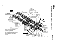
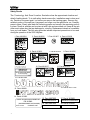
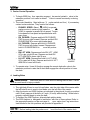
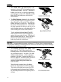
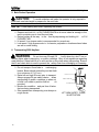
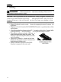
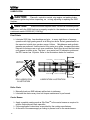
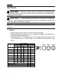
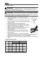
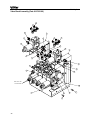
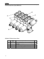
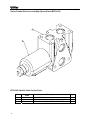
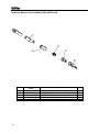
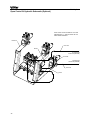
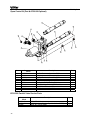
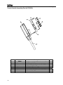
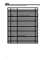
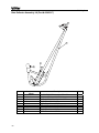
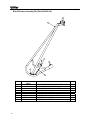
inland
Model 2500
For serial number 03BM2500001 and later
Operator’s and Parts Manual
Hayliner Bale Carrier
P4186
08/03
INLAND WARRANTY POLICY
Buhler Manufacturing products are warranted for a period of twelve (12) months (90 days for commercial
application) from original date of purchase, by original purchaser, to be free from defects in material and
workmanship under correct, normal agricultural use and proper applications.
Buhler Manufacturing’s obligations under this warranty shall be limited to the repair or exchange, at Buhler
Manufacturing’s option, of any Buhler Manufacturing product or part which proves to be defective as provided.
Buhler Manufacturing reserves the right to either inspect the product at the buyer’s location or have it returned to the
factory for inspection.
The above warranty does not extend to goods damaged or subject to accident, abuse or misuse after shipment from
Buhler Manufacturing’s factory, nor to goods altered or repaired by anyone other than an authorized Buhler
Manufacturing representative.
Buhler Manufacturing makes no Express Warranties other than those, which are specifically described. Any
description of goods, including any references and specifications in catalogues, circulars and other written material
published, is for the sole purpose of identifying goods and shall conform to such descriptions. Any sample or model
is for illustrative purposes only and does not create an Express Warranty that the goods conform to sample or model
shown.
The purchaser is solely responsible for determining suitability of goods sold. This warranty is expressly in lieu of
all other warranties expressed or implied. Buhler Manufacturing will in no event be liable for any incidental or
consequential damages whatsoever. Nor for any sum in excess of the price received for the goods for which liability
is claimed.
WARRANTY CLAIMS:
Warranty requests must be prepared on Buhler Manufacturing Warranty Claim Forms with all requested information
properly completed. Warranty Claims must be submitted within a thirty (30) day period from date of failure repair.
WARRANTY LABOR:
Any labor subject to warranty must be authorized by Buhler Manufacturing. The labor rate for replacing defective
parts, where applicable, will be credited at 100%
of the dealers posted shop rate.
Defective parts will receive an extra 10% discount to assist with
freight or other incidental costs.
GOVERNMENT LEGISLATION:
Warranty terms and conditions are subject to Provincial or State
legislation.
IMPORTANT FACTS:
Buckets and Bucket Tines Carry No Warranty
Bent Spears Carry No Warranty
Snowblower Fan Shafts Carry No Warranty
Mower Blades Carry No Warranty
Portable Auger Parts Have Two (2) Year Warranty
Printed in Canada
bühler
2500 Hayliner
OPERATORS AND PARTS MANUAL
Table of Contents
Description
TERMINOLOGY AND DECAL LOCATIONS ILLUSTRATIONS……..………...
GENERAL SPECIFICATIONS…..…………………………………………………
INTRODUCTION…………………………………………………………………….
Serial Decal Location…………………………………………………………….
Warranty Registration…………………………………………………………….
SAFETY………………………………………………………………………………
General Safety Notes…………………………………………………………….
Safety Decals……………………………………………………………………..
Important Precautions……………………………………………………………
PRE OPERATION CHECKLIST...…………………………………………………
OPERATION.………………………………………………………………………..
Attaching Bale Carrier to Tractor………………………………………………..
Attaching Bale Carrier Controls to Tractor……………………………………..
Carrier Controls Operation………………………………………………………
Loading Bales……………………………………………………………………..
Bale Pusher Operation…………………………………………………………...
Transporting 2500 Hayliner…...…………………………………………………
Unloading……..…………………………………………………………………..
LUBRICATION.………………………………………………………………………
Pivot Points………………………………………………………………………..
Roller Chain……………………………………………………………………….
Carrier Beams…………………………………………………………………….
MAINTENANCE…………………………………………………………………….
Fasteners………………………………………………………………………….
Hydraulic System…………………………………………………………………
Hydraulic Fitting Torques………………………………………………………..
Chain……………………………………………………………………………….
Wheels/Tires………………………………………………………………………
Storage…………………………………………………………………………….
APPENDIX LIST……………………………………………………………………..
APPENDIX A ASSEMBLY INSTRUCTIONS…………………………………….
APPENDIX B HYDRAULIC ASSEMBLY………………………………………...
APPENDIX C ELECTRICAL ASSEMBLY………………………………………...
APPENDIX D GENERAL ASSEMBLY…………………………………………...
CHECKLIST………………………………………………….………………………
Predelivery………………………………………………………………………...
Customer Delivery………………………………………………………………..
1
Page
2
3
4
4
4
5
5
7
8
9
10
10
10
11
11
13
13
14
15
15
15
15
16
16
17
17
18
18
19
20
21
25
48
51
71
71
71
Center Bale Stop
END
ORANGE
FLOURESCENT 17
SIDE
RED 15
Bale Lift Arm
Pusher
Bale Fork
Second Crossmember
YELLOW 16
Front Crossmember
AMBER
18
REFLECTOR
LEFT SIDE
YELLOW 16
13
Front Stop
YELLOW 16
7
12
YELLOW 16
Valve Bank
Jack
10
11
Note: 1) Refer to page 8 for detailed
information on safety decals
2) Awarness signs are shown on right side
only for clarification. Signs are provided on
both left and right sides except for numbers 9
and 14 which are only on the position
indicated.
4
RIGHT SIDE
9
2
16
YELLOW
1
6
5
14
bühler
Carrier Beam
Slow Moving
Vehicle
TERMINOLOGY AND DECAL LOCATIONS ILLUSTRATION
2
BACK
8
Clevis
2500 Hayliner
FRONT
bühler
2500 Hayliner
GENERAL SPECIFICATIONS:
Dimensions:
- Length: 45’ (13.7 m)
- Deck Length: 37’ (11.3 m)
- Width: 12’ 9” (3.9 m)
- Weight (empty): 9,375 LB (4252 kg)
- GVW: 37440 LB (16983 kg)
Capacity:
- Total bale payload: 28065 LB (12731 kg)
- Bales up to 6’ (1.8 m) diameter maximum to 4’ (1.2 m) diameter minimum
- Hay crop, small grains, and flax straw
- Sixteen 4’ (1.2 m) wide bales
- Fourteen 5’ (1.52 m) wide bales
Tires:
- 8-12.5L x 15 FI - 12 ply, Load Range F, Farm Hwy Service tire
- Six bolt heavy duty hubs with twine guards
- Walking beam axle design
Control Handle:
- Power: 12v
- Fuse: 15 amp (surge protection provided on machine)
Hydraulics:
- Two remote tractor hydraulics circuits required for operation
- Closed center hydraulic standard. Optional kit required for open center
- Two lift cylinders with restrictor
- Two tilt cylinders with restrictor
- Four 22.2 cu. inch (363.79 cu cm) hydraulic motors
- See Appendix B for details on hydraulic components
Tractor:
- Size: 100 hp (75kW) recommended
- Weight: As per ASAE specific ation ASAE S 365.4 the tractor must weight 25000 L B
(11340 kg) to adequately handle a GVW of 37440 LB (16983 kg)
- Maximum loaded towing speed 20 mph (32 km/h)
3
bühler
2500 Hayliner
INTRODUCTION
CAUTION:
Your 2500 Hayliner requir es a recommended minimum 100 hp (75kw)
tractor. The maximum loaded t ransportation speed of 20 mph (32 km/h) and 37440 LB
(16983 kg) must not be exceeded.
This manual has been provided as informa tion regarding the specifications, saf e
operation and maintenance of your agricultural 2500 Ha yliner. Read and understand
this manual and the tractor manual prior to operating to obtain the best use of operating
your 2500 Hayliner. Keep this manual for reference and to forward to new operators and
owners. Contact your local Buhler Inland
dealer if you requ
ire any assistance,
information or additional manuals.
Your new bale carrier is designed to re trieve, transport, and unload a wide range of
round bales. Sizes that can be accommodated range from 4’ (1.2 m) diameter to 6’ (1.8
m) diameter in a variety of hay crops as well as small grain and flax straw.
Serial Decal Location
The serial decal is loc ated on the left side of the front crossmember. Please record the
serial number in the space prov ided for futu re reference. The serial dec al will provide
the model and date of manufacture of the Hayliner and will be required to obtain correct
replacement parts and complete warranty claims.
For your records, record
Serial Number here:_________________________
Buhler Manufacturing
"a partnership"
farm king
allied
inland
Warranty Registration
The warranty registration and delivery report MUST be completed within thirty (30) days
of delivery to validate the warranty.
4
bühler
2500 Hayliner
SAFETY
Read and understand all the safety messages listed in this manual. For your safety and
the safety of others near t he machine, learn how to c ontrol and operate your 2500
Hayliner properly. It is your responsibility to inform subsequent operators and owners of
these precautions.
General Safety Notes
Keep young children away from machinery and bales at all times.
Be aware that accidents oft en happen when the oper ator is tired or in a hur ry to get
finished. T ake the time to consider the s afest way. Never ignore warning signs of
fatigue.
Keep hands, feet, clothing and hair away from moving
parts. Never attempt to clear obstructions or objects
from a machine while the engine is running.
Keep all shields in place. Never alter or remove safety
equipment.
Do not attempt to clear any blockage or reach into the 2500 Hay liner with your arm
or leg unless the tractor engine is stopped.
Do not load bales of sizes not out lined in the specifications section
Use proper lighting and safety warnings
when transporting equipment on public
roads and during darkness. The slow moving vehicle emblem must be visible. Check
with your local law enforcement agency for specific requirements.
Provide a first-aid kit for use in case of
emergencies.
The safety information in this manual does
not replace safety codes, insurance needs, or
laws governing your area. Be sure your machine
meets the standards set by these regulations.
Keep a fire extinguisher with the machine.
be sure the extinguisher is properly maintained
and be familiar with its proper use.
Wear close-fitting clothing and cover long hair. Never wear
dangling items such as scarves or bracelets.
Remember that YOU are the key to safety. Good safety
practices protect you and the people around you.
Follow all safety messages in the manual and on safety
signs located on the machine.
It is your responsibility to read and understand this manual
completely before operating the bale carrier.
5
bühler
2500 Hayliner
Never leav e the tractor unattended while the 2500 Hayliner is hooked up, alway s
shut tractor off and remove key before leav ing the tractor seat. A child or ev en a pet
could engage an idling machine.
Keep the 2500 Hayliner on so lid ground, rocks and holes c an be dangerous for
operation and movement.
Prior to use, check to ensure the attachment is properly hitched.
Improper use of the 2500 Hayliner and tractor can cause serious injury or death.
Never operate 2500 Hayliner with frayed or damaged hoses or leaking fittings. A
burst could cause one or more hydraulic components to behave erratically causing
serious injury or lose of life.
Operate 2500 Hayliner only while seated in the tractor seat.
Do not load bales im properly, always load according to the manual’s operation
procedures.
If for some reason you feel the tractor tipping immediately lower lift arms.
Do not rais e lift arms to extr eme heights while tractor is on an incline. Be alert for
terrain changes and adjust accordingly.
Allow for 2500 Hayliner and tractor length when turning.
Do not overload the GVW of 37 440 LB (16983 kg) and when loaded keep the speed
below 20 mph (32 km/h).
Before allowing any one to operate the mach ine, for however a short time or
distance, make sure they have been instructed in its safe and proper use.
Review the manual and all safety related items with all operators annually.
correct other operators not using re commended pr ocedures before an accident
occurs.
When ass embling, operating and servicing machinery, wear all the protective
clothing and personal safety devices that could be necessary for the job at hand.
Never work beneath a raised lift arm unless it
is securely supported. The control
handle can be moved or a hydraulic leak c ould caus e the arm to drop resulting in
serious injury or death.
Use only service and repair parts made or approved by the equipment manufacturer.
substituted parts may not meet strength, design, or safety requirements.
Do not modify the machine. Unauthorized modifications may impair the function
and/or safety and affect machine life.
Keep the area used for servicing machinery clean and dry. Wet
or oily floors are slippery. Wet spots can be dangerous when
working with electrical equipment. Be sure all electrical outlets
and tools are properly grounded.
Keep mac hinery clean. Straw and chaff on hot surfaces are a fire hazard. Do no
t
allow oil or grease to accumulate on service platforms, ladders or controls. Clean
machines before storage.
Never use gasoline, naphtha or any volatile material for cleaning purposes . Thes e
materials may be toxic and/or flammable.
When storing machinery, cover sharp or extending c omponents to prevent injury
from accidental contact.
6
bühler
2500 Hayliner
Safety Decals
The Terminology And Decal Location Illustration show the approximate location and
detail of safety decals. To in stall safety decals ensure the installation area is clean a nd
dry. Decide on the exact posit ion before you remove the backing paper. Remove the
smallest portion of the split bac king paper and align over the specified ar ea. Carefully
press in place. Slowly peel back the rema ining paper and smooth t he remaining portion
in place. Small air pockets can be pierc ed with a pin and smoothed out. Keep all dec als
clean and r eplace any that are damaged or missing. Replacement decals ar e available
from you local dealer. The follo wing pictorials indicate impor tant precautions to be used
during the operation of the 2500 Hayliner.
1. Part # 813624
5. Part # 813627
2. Part # 813625
3. Part # 21867
6. Part # 813632
4. Part # 813626
7. Part # 813633
8. Part # 813635
WARNING
HIGH-PRESSURE FLUID HAZARD
To prevent serious injury or death:
Relieve pressure on system
before repairing or adjusting or disconnecting.
Wear proper hand and eye protection
when searching for leaks. Use wood or
cardboard instead of hands.
Keep all components in good repair.
10. Part # 813637
SW700
11. Part # 813636
12. Part # 21980
19. Part # A7017-00
13. Part # 28949
14. Part # 813952
BUHLER HAYLINER 1500/2500 SNUBBER UNIT
P/N: 813949
(NO SERVICEABLE PARTS INSIDE)
CONTINUITY LIGHT
DECAL PN: 813952
7
15. Part # 967053
RED REFLECTIVE
16. Part # 967055
YELLOW REFLECTIVE
17. Part # 813631
ORANGE FLUORESCENT
18. Part # 813628
AMBER REFLECTIVE
bühler
2500 Hayliner
Important Precautions
The alert symbol is used throughout this manual . It indicates at tention is r equired and
identifies hazards and alerts you that your safety is involved. Follow the recommended
precautions.
CAUTION
Indicates a potentially hazardous situation, which may result in
injury. It may also be used to alert against unsafe practices.
WARNING
The warning symbol indicate
s a potentially hazardous
situation, which could result in death or serious injury and includes haz ards that are
exposed when guards are removed. It may also be used to alert against unsafe
practices.
DANGER
The danger symbol indicates
an imminently hazardous
situation, which will result in death or seri ous injury. This signa l word is limited to the
most extreme situations, typically for
machine c omponents, which for functional
purposes, cannot be guarded
8
bühler
2500 Hayliner
PRE-OPERATION CHECKLIST
CAUTION
Make sure the tractor has a 100 hp (75 kw) or greater rating
and a mas s of 25000 LB (11340 kg). Make sure the drawbar is c apable of s upporting
the 2500 Hayliner empty or loaded.
WARNING
The tractor must be equipped with an approved Roll over
Protection Structure (R OPS) and safety belts to help pr event personal injury or death
caused by tractor roll over.
To ensure safe and proper operation of the 2500 Hayliner, inspect the following items
prior to operation and daily thereafter. Refer to operation, lubrication and m aintenance
sections for detailed instructions.
Prior to first use verify that the 2500 Hayliner has been properly assembled and that
the operator understands the safety, operating, and maintenance requirements.
Check for missing fas teners and replace if necessary. Refer to maintenanc e section
for details.
Check and maintain proper tire pressure of 90 psi (620 kpa).
Check for loose wheel bolts. Bolts must be torqued to 125 ft LB (170 Nm).
Clean 2500 Hayliner of any foreign mate rial that may have accumulated from
previous run.
Lubricate all points requiring daily lubrication.
Check chain tension and adjust if necessary with front sprocket adjusting bolt
(approximately 6” (15 cm) of upward slack). This is verified by rais ing the c hain b y
hand.
Ensure top surface of bale carrier beams are properly coated with a graphite coating
to reduce bale friction while pushing bales back.
Ensure that the tractor used to pull the 250 0 Hayliner is in workin g order ac cording
to the tractor manual.
Verify the 2500 Hayliner is properly coupled to the tractor with the safety chain.
Inspect all safety re flective decals, sl ow moving ve hicle dec als and light s where
applicable.
Inspect the hydraulic system on the 2500 Hay liner and your tractor for leaks or any
other damage.
Ensure the control handle actions reflect the movements of the 2500 Hayliner.
Inspect all electrical connections to ensure proper function of the machine
Ensure transport safety chain is diseng aged from bale lift arm and stored on chain
lug located on second cross member. Failure to do so may cause damage to lift arm.
.
9
bühler
2500 Hayliner
OPERATION
CAUTION
Prior to operation ensure
the operator has read and
understands the safety requirements of t he 2500 Hay liner. Ensure the pre-operation
checks have been completed prior to operation.
1. Attaching Bale Carrier To Tractor
CAUTION
Shut off tractor, engage parking brake and remove key before
working around 2500 Hayliner. Refer to tractor manual for tractor parking procedures.
CAUTION
Use only the drawbar to couple the 2500 Hayliner to the
tractor. Ensure drawbar is capable of handling the 2500 Hayliner load. The tractor must
have a minimum mass of 25000 LB (11340 kg) and recommended 100 hp (75 kw).
Using the t ongue jack, raise tongue to alig n with hitch pin, adjust clevis position
as necessary to level the carrier beams.
Position tractor and secure with locking type drawbar pin (not supplied). Use an
approved hitch pin with a mechanical retainer.
Route safety chain around the hitch cl evis, around drawbar support and back
hook. Refer to tractor manual for further drawbar instructions.
Do not use intermediate support on drawbar as attaching point.
Store safety chain off the gr ound when not in use. If sa fety chain is damaged in
any way, contact your dealer for a replacement.
2. Attaching Bale Carrier Controls To Tractor
Bale raise and pus h functions are cont rolled by the 2500 Hayliner v
alve.
Pressure and tank ar e supp lied by two hos es complet e with blac k hydraulic tip
covers. The retract hose is des ignated wi th a check valve and ensures proper
flow through the valve. Connect t ank hose to retract circuit and extend hose to
opposite extend port see Appendix B for schematic.
The tilt function is contro lled by the tractor’s remo te valve. Extens ion and
retraction are supplied by two hoses complete with red hydraulic tip covers.
Connect control handle harness to the ma chine harness. Connec tion is made at
the snubber unit by matching the appropriate socket and plug.
Power to operate the 2500 Hayli ner is supplied by the trac tors 12 volt electrical
system. Connect the red wire to t he tractor positive and green to tractor gro und.
Connection may be made via tractor accessory plug or alternate method. The 15
amp fuse must be used on the positive wire as supplied.
Verify 2500 Hayliner operation matches 2500 Hayliner control handle decal.
10
bühler
2500 Hayliner
3. Carrier Control Operation
To begin 2500 Hay liner operation engage t he remote hydraulic valve in the
extension position. Lock valve in detent. Valve to remain constantly on during
operation.
The control handle is fitted with one (1) rocker switch and four ( 4) momentary
contact rocker switches. They function as follows:
o PUSHER SPEED: Select
(HIGH) to operate
pusher motors in series at high speed or
(LOW) to operate in paralle l at low speed. T orque
is increased at low speed and pushes bales with
more force.
o RH PUSHER: Depress and hold RH PUSHER
FWD to move right forward. Depress and hold RH
PUSHER BACK to move right pusher back.
o LH PUSHER: Depress and hold LH PUSHER
FWD to move left pusher forward. Depress and
hold LH PUSHER BACK to
move left pusher
back.
o RH LIFT ARM: Depress and hold RH LIFT ARM
UP to rais e right lift arm. Depress and hold RH
LIFT ARM DN to lower right lift arm.
o LH LIFT ARM: Depress and hold LH LIFT ARM
CONTROL
UP to raise left lift arm. Depress and hold LH LIFT
HANDLE
ARM DN to lower left lift arm.
PUSHER
SPEED
LH PUSHER FWD
RH PUSHER FWD
LH PUSHER BACK
RH PUSHER BACK
LH LIFT ARM UP
RH LIFT ARM UP
LH LIFT ARM DN
RH LIFT ARM DN
To operate raise / lower tilt function engage the remote hydraulic valve in the
extension position to raise the tilt deck and engage the retract position to lower
the deck.
4. Loading Bales
WARNING
Make sure area is c lear before lo wering bale lift arms. Failure
to do so could result in injury or death.
The right bale lift arm is used to load bales onto the right side of the carrier while
the left bale lift arm is used to load bales onto the left side of the carrier.
Align the tractor and 2500 Hayliner as indic ated in the pictoral for pick up method
used. Slowly approac h the bale at 5 mph ( 8 km/h) while loading. When bale is
properly captured begin to raise the bale.
To balance the 2500 Hayliner, alternate bale picking sides.
The 2500 Hayliner is designed to load bales with one of three options. Refer to
the appropriate section on the next page fo r your option load ing instructions.
Instructions for the fork positions are provided in appendix A.
NOTE:
11
Before loading bale the pusher must
be at the front of the carrier deck.
bühler
The Fixed Pick Up Arm requires the
operator to drive at 90° to the baling direction.
The bales are loaded “End On”. The bale is
loaded onto the carri er deck by depressing
and holding LH or RH LIFT ARM UP until the
bale rolls off the pickup arm and onto the
carrier beams.
The Bale Deflector attached to the fixed pick
up arm allows the bales to be picked up from
either “End On” or “S ide On.” The deflector
rotates the bale 90° before it is lifted up ont o
the carrier. Forward travel is us ed to rotate
the bale. Approach the ba le so that the out er
end of the bale rides up on the bale deflec tor
as the loading arm moves under the bale.
To pick up bales that are placed “End On,”
drive so the inner arm of the loading fork is
against the inner edge the bale. The bale will
then be loaded onto the ca rrier in the sam e
direction as it was picked up. Continue to
load using fixed arm instrucitons.
2500 Hayliner
FIXED PICK UP ARM
BALE DEFLECTOR
NOTE:
The bale should be contac ted about 12” (30 cm) from its outer end when
using the bale deflector. Contacting the bale further to the inside may result in damage
to the deflector, bale lift arm or bale.
The Rotating Pick Up Arm (RPU) loads
bales “side on”. The lift arm starts in the
lowered position. Drive forward until the forks
are positioned around t he ends of the bale
with the inside stationar y fork as close as
possible to the bale. D epress and hold LH or
RH LIFT ARM UP. The bale is then squeezed
on end until the pressure matches the
sequence valve setting that rotates and
raises the bale.
When the bale is raised above the beam
release by depressing LH or RH arm down.
This releas es the bale and returns the RPU
to the ready state for the next bale. Refer to
the assembly instructions for adjusting RPU’s
settings.
12
RPU LOADING BALE
RPU RAISING BALE
bühler
2500 Hayliner
5. Bale Pusher Operation
CAUTION
To avoid misbalanc ed loads t he operator is only required to
push back one bale length to prepare for the next bale.
NOTE: Lower loading arm before operating the pusher.
Depress and hold LH or RH PUSHER BACK an d move bales far enough to the
rear to provide room to load the next bale.
Return pusher all the way to the front by depressing and holding LH
or R H
PUSHER FWD.
Hi speed / Low torque mode is recommended for normal use.
Low speed / High torque mode is for heavie r payloads or situations where bales
are wet or resist sliding.
6. Transporting 2500 Hayliner
WARNING
Do not tow over 20 mph (32
km/h) when loa ded. Turn on
flashing lights when transporting on public r oadways. Obey lo cal regulations regarding
road transport. Raise bale lift ar m and use the sa fety chain when transporting. Ensure
the lift arm chain latch is used to prevent the safety chain from dislodging or loosening.
Do not transport if end bale is overhanging
beams. Beam should extend beyond last bale
for a minimum of 2’ (61 cm).
Raise left and right lift a rms prior to transport.
Always engage lift arm safety chains when
transporting on public r oadways or when not
in field. Lock chain in position with lat
ch
provided.
Monitor the condition and pos ition of bales
that are being transported.
Slow speed when transpor ting over bumps or
rough terrain.
13
LATCH
SAFETY CHAIN
LIFT ARM
LIFT ARM SAFETY CHAIN
ILLUSTRATION
bühler
2500 Hayliner
7. Unloading
DANGER
Make sure area is c lear before unloading. Failure to do s
could result in serious injury or death.
o
NOTE:
Left or rig ht decks can be unloaded indivi dually or together. However, the
pusher moves faster and has more torque
when operated individ ually. Do not run
pushers all the way t o the end, the result ing shock load may cause damage to chain
and drive.
Extend tilt cylinder to raise carrier beams by engaging the tractor’s extens ion
hydraulics.
Depress and hold LH and/or RH PUSHER BACK switch to push the bales off the
carrier beam.
Once the rear bale has been pushed off t he carrier, slowly driv e forward while
pushing the bales back (unloading)
to keep all bale ends in contact.
When amber reflector on inside of the carri er
beam becomes visible stop the pusher. The
reflector is approximately 26” (66cm) from the
end of the beam.
Slowly driv e forward to unload the last bale.
Retract the tilt cylinder to lower the beam and
begin the next loading cycle.
AMBER REFLECTOR
Return PUSHER to the front of the 2500
LOCATION
Hayliner to prepare for the next cycle.
14
bühler
2500 Hayliner
LUBRICATION
CAUTION
Place all c ontrols in neutral, stop engine, set parking brake
and remove ignition key before inspecting, se rvicing, adjusting or repairing the 2500
Hayliner.
CAUTION
Ensure the 2500 Hayliner tires a nd hitch ar e securely block.
Otherwise, verify the 2500 Hayl iner is properly coupled to the drawbar on a tractor with
a minimum mass of 25000 LB (11340 kg).
Pivot Points
Lubricate 2500 Hay liner bushings and pivo ts every eight hours of average
operation with high-grade greas e at all fitting loc ations. Select grease based on
the expect ed outside tem perature range. Lithium, Molybdenum and synthetic
greases are preferred. Use the tractor hour meter as a guide. Increase lubrication
intervals for extreme use or adv erse conditions. Each pivot sh ould be lubric ated
until grease is visible at pin. The fixed arm carrier has 16 lubrication points and
the RPU carrier has 18 points. Refer to the illustrations below for locations.
AXLE BEARING
HYDRAULIC CYLINDER END
RPUPIVOT LEFT
ANDRIGHTSIDES
BUSHING
HYDRAULIC CYL
END
BUSHING
AXLE BEARING
RPU LUBRICATION
ILLUSTRATION
HYDRAULIC CYLINDER END
LUBRICATION ILLUSTRATION
Roller Chain
Manually brush an SAE lubricant while chain is stationary.
Lubricate the chains every time bolt torque maintenance is performed.
Carrier Beams
Apply a graphite coating such as Slip PlateTM to the carrier beams as required to
ensure a smooth push back operation.
Follow application instructions as provided by the coating manufacturer.
At the end of the season apply a coating to prevent rust on the carrier beams.
15
bühler
2500 Hayliner
MAINTENANCE
CAUTION
Place all c ontrols in neutral, stop engine, set parking brake,
remove ignition key and wait for all moving parts to stop before serv icing, adjusting or
repairing the 2500 Hayliner.
CAUTION
Ensure the 2500 Hayliner tires a nd hitch ar e securely block.
Otherwise, verify the 2500 Hayl iner is properly coupled to the drawbar on a tractor with
a minimum mass of 25000 LB (11340 kg).
NOTE:
conditions.
Service intervals should be increased w hen operating in extreme or difficult
1. Fasteners
Inspect all bolt torques after first use and 50 hours thereafter.
Periodically inspect for broken or missi ng fasteners. Replace with fasteners of
similar size and equivalent grade.
The table below list t he correct torque va lues for various bolts and cap scr ews
used on the bale carr ier. Tighten all bolt s to specified values unless other wise
noted.
BOLT TORQUE
SAE 5
BOLT
DIAMETER
"A"
lb-ft
N.m
lb-ft
N.m
lb-ft
N.m
1/4"
6
8
9
12
12
17
SAE 2
5/16"
10
13
19
25
27
36
3/8"
20
27
33
45
45
63
7/16"
30
41
53
72
75
100
1/2"
45
61
80
110
115
155
9/16"
70
95
115
155
165
220
5/8"
95
123
160
215
220
298
3/4"
155
225
290
390
400
540
7/8"
170
230
420
570
650
880
1"
225
305
630
850
970
lb-ft
125
33
1320
LOCATION
WHEEL HUB BOLTS
ALL CARRIAGE BOLTS
16
SAE 8
N.m
170
45
bühler
2500 Hayliner
2. Hydraulic System
WARNING
Escaping fluid under pressure can have sufficient force to
penetrate the skin, causing serious personal in
jury. Before repairing, adjusting, or
disconnecting lines, be sure to relieve all pressure.
WARNING
Never operate the 2500 Hay liner with frayed or damaged
hoses or leaking fittings. A burst would cause the lift arm to drop suddenly and result in
serious injury or death and cause damage to the loader or tractor.
Before applying pressure
to the system, be sure all
connections are tight and the lines, pipes, and hoses are
not damaged.
Wear proper hand and eye pr otection when searching for
leaks. Us e a piece of wood or cardboard instead of hand
to check for leaks.
Maintain all components in good working order.
If injured by escaping fluid, see a doctor at once. Serious
infection or toxic reaction c an develop if proper medical
treatment is not administered immediately.
Regularly check the f luid lev el in the tractor reservoir and
follow the maintenance procedures in the tractor
Operator’s Manual.
Regularly inspect cylinders, hoses and fittings for leaks,
crimps and abrasions or other signs of wear and tear or
impending failure.
Ensure hoses do not bind or
stretch during operation.
Always keep hoses tied or supported to prevent rubbing against sharp areas or
being pinched. We suggest using tie wraps to support hoses.
Replacement hoses must have a worki ng pressure of 3000 ps i (20685 k pa) or
higher.
3. Hydraulic Fitting Torques
Dash Size
Thread
Size
-04
-05
-06
-08
-10
-12
-14
-16
-20
-24
7/16-20
1/2-20
9/16-18
3/4-16
7/8-14
1-1/16-12
1-3/16-12
1-5/16-12
1-5/8-12
1-7/8-12
17
Jam Nut or Straight
ORB Fitting Torque
(ft-lbs)
(NM)
14-16
20-22
18-20
24-27
24-26
33-35
50-60
68-78
72-80
98-110
125-135
170-183
160-180
215-245
200-220
270-300
210-280
285-380
270-360
370-490
SAE 37° (JIC)
Swivel Nut Torque
(ft-lbs)
(NM)
10-11
13-15
13-15
18-20
17-19
23-26
34-38
47-52
50-56
69-76
70-78
96-106
80-90
110-122
94-104
127-141
124-138
169-188
156-173
212-235
bühler
2500 Hayliner
4. Chains
Check for proper chain tension and sprocke t
alignment after first use and every 50 hours
thereafter.
Turn the front sprocket adjusting bolt
clockwise until there is approximately 6” (15
cm) of upward slack in the chain at the center
of the track. Clockwise increases tension and
counter clockwise reduces tension.
Proper chain tension
may be verified by
raising the chain by hand.
See lubrication section for further
maintenance instructions.
FRONT ADJUSTING
BOLT
5. Wheels / Tires
Inspect hub bolts after first use and 50 hrs thereafter. Hub bolts must be torqued
to 125 ft-lb (170 Nm).
Thread-locking compound such as Lockt ite 242 is recommended for the hub
bolts.
Ensure that dust caps are firmly in place.
Check tire pressure regularly: 90 psi (620 kpa).
The wheel bearings should be inspec ted and re-packed annually with a SAE
multi purpose type grease. If hub is
supplied with grease fitting grease every
500hrs.
Air valve should face away from the hub.
18
bühler
2500 Hayliner
6. Storage
CAUTION
Place all c ontrols in neutral, stop engine, set parking brake
and remove ignition key before inspecting, servicing, adjusting or repairing the 2500
Hayliner.
CAUTION
Ensure the 2500 Hayliner tires a nd hitch ar e securely block.
Otherwise, verify the 2500 Hayl iner is properly coupled to the drawbar on a tractor with
a minimum of 25000 LB (11340 kg).
Start of Season
Clean and inspect the bale carrier when taking it out of storage. Ensuring that the
bale carrier is in opt imum condition at the start of the seas
on reduces the
chances of a costly breakdown during the season.
Clean and inspect chains and chain rollers for excessive wear or stiffness. Check
for proper adjustment and alignment.
Lubricate entire bale carrier. Ensure that all grease fittings are in place and taking
grease properly.
Operate the bale car rier for a short ti me. Check that all mov ing parts are
operating freely. Check for hydraulic leaks.
Inspect and repack wheel bearings with a SAE multi purpose type grease.
Replace and secure safety shields. Review safety regulations.
Check all bolts for tightness. Replace lost or worn bolts.
Check that tires are properly inflated.
Review the Operator’s Manual.
During The Season
At the end of each day of operation park the bale carrier in a clean, dry, sheltered
area.
Lubricate areas requiring daily lubrication.
Remove any build up of hay or straw.
End Of Season
Replace worn or damaged parts and replac e if necessary. To avoid costly delays
contact your dealer for replacement parts before the start of the next season.
Store the bale carrier in a clean, dry, sheltered area.
Replace all missing or broken bolts with bolts of similar size and grade.
Clean the baler carrier thoroughly. Dirt draws moisture that rusts metal.
Repaint chipped or worn areas. Paint is available from your dealer.
Clean chains and brush with SAE light machine oil (or equivalent) to prevent rust.
Repaint the top of the carrier beams wit h a graphite paint such as Slip Plate TM to
prevent rust.
19
bühler
2500 Hayliner
APPENDIX LIST
Description
Appendix
Assembly Instructions……………….…….………………………………….
A
Hydraulic Assembly……………...……………………………………………
B
Electrical Assembly……………...………………………………..…………..
C
General Assembly……………………………………….…………………...
D
20
bühler
2500 Hayliner
APPENDIX A
Assembly Instructions
Table of Contents
Description
Page
Center Bale Stop……………………………………………………………………. 22
Fixed Loading Arm..………………………………………………………………… 22
Bale Deflector Arm Assembly.…………………………………………………….. 23
RPU Assembly………………………………………………….…………………... 23
21
bühler
2500 Hayliner
CAUTION
Make sure area is c
sufficient room for safe assembly.
lear of obstructions, well lit, and ha
s
CAUTION
Ensure the 2500 Hayliner tires a nd hitch ar e securely block.
Otherwise, verify the 2500 Hayl iner is properly coupled to the drawbar on a tractor with
a minimum of 25000 LB (11340 kg).
Center Bale Stop
Remove the hardware that is attached to the center bale stop a nd place c enter
bale stop bar on bolt plates in the position shown on page 3. Torque the provided
hardware to the spec ifications listed on the bolt char t. Tie wrap the hydraulic
hoses that run to the lift and tilt cylinders under the roll bar.
Fixed Lift Arm
NOTE:
Hydraulic Assembly methods and layout s are common to the right and left
sides. Only one side of each component is shown in this manual.
CAUTION
Stay clear of the arms when
testing a finished ass embly.
Ensure during assembly to k eep your entir e body out from underneath parts that are
being attached to the main frame.
Remove lif t arm pivot pins that are installed
on the 2500 Hayliner.
Thoroughly lubricate all pins inv olved in the
assembly with a SAE multi purpose grease.
Align arm to pivots with open end of arm
36.0"
facing forward and reinstall pins with
hardware provided and torque to
FIXED LIFT ARM
specifications called for in the bolt chart.
ATTACHMENT
Remove the lift cylinder pin from the arm.
Align the lift cylinder rod and reinstall the pin.
Adjust the outside bale fork to be posit ioned at the end of the lift arm and the
inner bale fork about 36” (91 cm) from the end.
Recheck all hardware so that every bolt ed connection on the lift arm is torqued
according to the specifications of the bolt chart.
For first operation, cycle the lift arm slo wly with a bale and Inspect just before
lifting bale from ground.
Approach the bale and inspect to ensure the spacing of the forks is accurate.
Finish the cycle and observe how the bale transits from the forks to the carrier
beam. If transition is smooth wit h minimum bale binding assembly is completed.
If not adjust the forks to a different location and try until loading is smooth.
22
bühler
2500 Hayliner
Bale Deflector Arm Assembly
Remove all hardware that is included with the
deflector assembly.
Remove the two top bolts from outer fork on
lift arm.
Maintain the spacing of the forks if already
preset. If not set spacing as des cribed in the
fixed pick up arm assembly section.
Insert the coned end of the deflector onto the
end of the outer fork.
Align the bolt holes from the removed bolts
on the outer fork and t he end of the deflector
attachment.
Insert hardware suppli ed with t he deflect or
the same way the hardware was installed
before the attachment was added.
Torque all hardware according to the bolt
chart and tighten the s et screws on the cone
also according to the chart.
During first bale lift, cycle slowly and watch
for excessive flexing or movement of the
deflector. If movement is detected stop cycle
and retorque all hardware involved.
RPU Assembly
Remove lif t cylinder and install Pilot Check
assembly (see Appendix B)
Reinstall cylinder at base end only.
Lubricate all pins involved in RPU attachment
with a SAE multi purpose grease.
Align arm to pivots with open end of arm
facing away from t he 2500 Hayliner and
reinstall pins with hardware provided and
torque to specifications called for in the bolt
chart.
23
BALE DEFLECTOR
ATTACHMENT ASSEMBLY
LAYOUT
Remove the lift cylind er pin
from the RPU arm.
RPU ATTACHMENT
ASSEMBLY LAYOUT
bühler
2500 Hayliner
Align the lift cylinder rod and reinstall the pin.
ADJUSTABLE FORK
Adjust the outside bale fork to be positioned
at the end of the lift arm and the inner bale
fork 6” (15 cm) to 8” (20 cm) bigger than the
BALE WIDTH + 6” TO 8”
size of bale that is being loaded.
Install the hydraulics according to the way
the hydraulic assembly Appendix B calls out.
ROTATING PICK UP ARM
Recheck all hardware so that every bolted and
hydraulic connection on the lift arm is torq ued according to the specifications of
the torque charts.
The RPU cycle should begin with a squeez e action, then lift and rotate. After
rotation is complete the lift continues until the bale is above the carrier beams.
Release LIFT ARM UP when bale is above the carrier beam. Depress LIFT ARM
DN to release the bale and return to ground level ready for the next bale.
For the fir st operation, cycle the lift arm slowly with the ba le and observe the
RPU operation.
Approach the bale slowly, once the bale is captured in the forks press the lift
switch. The bale is squeezed until the pr essure in the sequenc e valve has been
achieved which is preset at 1800 psi (12400 kpa).
If bale is not held in between the forks in crease the sequence valve pressure b y
turning the setscrew cl ockwise. Refer to th e RPU Rotate Cylinder drawing for
adjustment location of the setscrew. Verify that the fork spacing is accurate and
refer to the drawing on this page for fork adjustments.
The lift and rotate sequence won’t begin unt il the clamp pressure is met within
the sequence valve.
When the clamp pressure is met, the lifting action should start before the rotating
action to minimize bale damage from the moving ground.
To increase lift prior to rotate turn the restrictor knob clockwise. Refer to the RPU
Rotate Cylinder drawing for more information.
Continue to raise the bale until it is positioned above the carrier beam.
Release the bale by lowering the lift arm.
Finish the cycle and observe how the bale transits from the forks to the carrier
beam. If transition is smooth wit h minimum bale binding assembly is completed.
If not adjust the forks to a different location and try until loading is smooth.
24
bühler
2500 Hayliner
APPENDIX B
Hydraulic Assembly
NOTE:
1) Hydraulic Assem bly methods and layo uts are common to the right and
left sides. Only one side of each component is shown in this manual.
2) Seal Kit s and Service Parts are only list ed in the parts lists and are not indic ated on
the illustrations.
Table of Contents
Description
Carrier Hydraulic Assembly Schematic…………………………………………...
Valve Bank Assembly………….….……………………………………….…....
FPS Directional Valve Bank Assembly……………………………………...
Series Parallel Valve (Low and High Speed)……………………………….
Hydraulic Return Line Assembly………………………………………………..
Hydraulic Pressure line Assembly……………………………………………...
Carrier Tilt Assembly……………………………………………………………..
Fixed Pick Up Cylinder Assembly………………………………………………
Carrier Tilt Cylinders Hydraulic 3/8 line………………………………………...
Pusher Motor Assembly………………………………………………………….
Carrier Hydraulic Assembly Hardware…………………………………………
Fixed Pick Up Arm Hydraulic Assembly Schematic……………………………..
RPU Hydraulic Assembly…………………………………………………………...
RPU Squeeze Cylinder…………………………………………………………..
RPU Lift Cylinder………………………………………………………………….
Pilot Check Valve Assembly………………………………………………….
RPU Rotate Cylinder……………………………………………………………..
Open Center Kit Hydraulic Schematic.……………………………………………
Open Center Kit Assembly………………………………………………………
2500 Hayliner Hydraulic Schematic……………………………………………….
25
Page
26
28
30
31
32
33
34
35
36
37
38
39
40
41
42
43
44
45
46
47
*29172
TO TRACTOR
COUPLER (EXTEND)
9
TO TRACTOR
COUPLER (RETRACT)
NOTE: ALL ITEMS THAT ARE MARKED
WITH A "*" ARE NOT SUPPLIED ON
THE MAIN ASSEMBLY
9
4
11
3
2
*812270
1
3
*812270
5
11
7
bühler
10
Carrier Hydraulic Assembly Schematic (Part # A7000-04)
26
1
9
8
TO TRACTOR
COUPLER
(EXTEND)
4
2500 Hayliner
6
TO TRACTOR
COUPLER
(RETRACT)
bühler
2500 Hayliner
Carrier Hydraulic Assembly (Part # A7000-04)
Item
1
2
3
4
5
6
7
8
9
10
11
27
Component
Part #
115169
29108
29110
29176
A7005-00
A7010-00
A7011-00
A7012-00
A7013-00
A7014-00
A7007-00
Description
HOSE 3/8 X 132 9/16 SWFJIC X SWFJIC
HOSE 1/2 X 16 3/4 SWFJIC X SWFJIC
HOSE 1/2 X 32 3/4 SWFJIC X SWFJIC
HOSE 1/2 X 54 3/4 SWFJIC X SWFJIC
VALVE BANK ASSEMBLY
HYD ASSY 1/2 X 130 RETURN LINE
HYD ASSY 1/2 X 130 PRESSURE LINE
TILT ASSY 3.0 X 16.0 CYLINDER
TILT ASSY LIFT ARM CYLINDER
TILT ASSY CYLINDER 3/8 HYDRAULIC LINE
PUSHER MOTOR ASSEMBLY
Qty
4
4
4
2
1
1
1
1
3
2
2
bühler
2500 Hayliner
Valve Bank Assembly (Part # A7005-00)
11
11
12
2
10
11
11
3
3
13
12
12
13
1
8
8
14
14
10
10
10
8
7
12
10
8
2450 PSI PLUGS
TO THE FRONT
9
4
5
4
4
28
6
4
bühler
2500 Hayliner
Valve Bank Assembly (Part # A7005-00)
Item
1
2
3
4
5
6
7
8
9
10
11
12
13
14
29
Component
Part #
C7041-00
C7042-00
811414
81549
E7050-00
B7009-00
E2781-00
810582
812362
812080
813667
812081
B7010-00
812107
Description
VALVE BANK MOUNT WELDMENT LH
VALVE BANK MOUNT WELDMENT RH
ELBOW 90 3/4 MORB ADJ X 3/4 MJIC
BOLT HEX 0.313 NC X 0.75 GR5PL
PAN / VALVE BANK
FPS DIR VALVE ASSY 4 BANK
FLOW RESTRICTOR
BOLT HEX 0.313 NC X 3.00 GR5PL
NUT LOCK (STEEL) 0.313 NC GRBPL
ADAPTOR STR 3/4 MORB X 3/4 MJIC
TEE RUN 1/2 MJIC X 3/4 MORB
PLUG 3/4 MORB STL. 721-FSO-08
SERIES PARALLEL VALVE (2 SPEEDS)
ADAPTOR STR 9/16 MJIC X 3/4 MORB
Qty
1
1
2
8
1
1
1
4
12
7
4
4
2
4
bühler
2500 Hayliner
FPS Directional Valve (Part # B7009-00)
2
1
1
2
3
4
B7009-00 FPS Valve Service Parts
Item
30
1
2
Component
Part #
22208-02
22149
3
4
5
6
22208-01
22083-03
X2684
813842
Description
Qty
MV4-17 LOCK VALVE
CROSS OVER RELIEF VALVE HAYLINER SET @ 800
/ 2450 PSI
MVA-17 SPOOL SECTION
C07-12TD COIL
SEAL KIT VALVE BANK (ITEM NOT VISIBLE)
BOLT KIT VALVE (4) BANK
4
2
4
8
4
1
bühler
2500 Hayliner
Series Parallel Valve Low and High Speed (Part # B7010-00)
2
1
B7010-00 Parallel Valve Service Parts
Item
1
2
3
31
Component
Part #
22083-03
22083-01
X2684
Description
C07-12TD COIL
SERIES PARALLEL VALVE (LOW &HIGH SPEED)
SEAL KIT VALVE BANK (ITEM NOT VISIBLE)
Qty
1
1
1
bühler
2500 Hayliner
Hydraulic Return Line Assembly (Part # A7010-00)
1
3
2
5
4
Item
1
2
3
4
5
32
Component
Part #
29170
812841
813119
813305
813666
Description
HOSE 1/2 X 130 3/4 MORB X 3/4
MALE TIP 0.5 BODY 0.75 ORB
ADAPTOR STR 3/4 MORB X 3/4 MORB
DUST CAP 0.5 BLACK
VALVE CHECK 3/4 ORB LINE
Qty
1
1
1
1
1
bühler
2500 Hayliner
Hydraulic Pressure Line Assembly (Part # A7011-00)
1
2
3
Item
1
2
3
33
Component
Part #
29170
812841
813305
Description
HOSE 1/2 X 130 3/4 MORB X 3/4
MALE TIP 0.5 BODY 0.75 ORB
DUST CAP 0.5 BLACK
Qty
1
1
1
bühler
2500 Hayliner
Carrier Tilt Assembly (Part # A7012-00)
1
3
5
1
5
4
2
Item
1
2
3
4
5
Component
Part #
29172
22510
813640
E2872-00
887572
Description
Qty
HOSE 3/8 X 18 9/16 SWFJIC X SWFJIC
CYLINDER 3.0 DIA X 16 INLAND
ELBOW 90 9/16 MORB ADJ 3/8
ELBOW RESTRICTOR MALE 90°
TEE 9/16 MJIC X 9/16 SWFJIC
2
1
1
1
2
22510 Cylinder 3.0 Diameter Service Parts
Component
Part #
813407
X2504
24957
115519
24958
34
Description
LOCKNUT 1.00 NF
SEAL KIT FOR ITEM 22510
TUBE WELDMENT 3.0 DIA
SHAFT WELDMENT 1.50 X 22.63
HEAD PLATE 3.0 X 1.50
Qty
1
1
1
1
1
bühler
2500 Hayliner
Fixed Pick Up Cylinder Assembly (Part # A7013-00)
TO LIFT PORT ON MAIN VALVE BANK (FRONT PORT)
USE 3/8 X 132" HOSE SUPPLIED WITH MAIN FRAME
1
TO LIFT PORT ON VALVE BANK (REAR PORT)
USE 3/8 X 132" HOSE SUPPLIED WITH MAIN FRAME
3
2
Item
1
2
3
Component
Part #
813640
22510
E2872-00
Description
Qty
ELBOW 90 9/16 MORB ADJUSTABLE X 3/8
CYLINDER 3.0 DIA X 16 INLAND
RESTRICTOR ELBOW MALE 90
1
1
1
22510 Cylinder 3.0 Diameter Service Parts
Component
Part #
813407
X2504
24957
115519
24958
35
Description
LOCKNUT 1.00 NF
SEAL KIT FOR ITEM 22510
TUBE WELDMENT 3.0 DIA
SHAFT WELDMENT 1.50 X 22.63
HEAD PLATE 3.0 X 1.50
Qty
1
1
1
1
1
bühler
2500 Hayliner
Carrier Tilt Cylinders Hydraulic 3/8 Line (Part # A7014-00)
1
3
2
Item
1
2
3
36
Component
Part #
29173
812841
813303
Description
HOSE 3/8 X 216 9/16 SWFJIC X ¾RB
MALE TIP 0.5 BODY 0.75 ORB
DUST CAP 0.5 RED
Qty
1
1
1
bühler
2500 Hayliner
Pusher Motor Assembly (Part # A7007-00)
8
4
6
7
1
9
5
2
10
Item
1
2
3
4
5
6
7
8
9
10
Component
Part #
C7031-00
C7030-00
C2768-00
967275
84051
84048
813663
B2799-00
812270
811416
3
Description
Qty
SPROCKET DRIVE WELDMENT
MOTOR 22.2 CU MT WELD
SPROCKET ADJUSTING BOLT FRONT 1NC
BOLT HEX 0.500 NC X 2.00 GR8PL
NUT HEX JAM 1.00 NC GR2
WASHER 0.500 FLAT SAE BS PL
NUT LOCK (STEEL) 0.500 NC GRCPL
MOTOR 22.2 CU PAINT YELLOW
HOSE 1/2 X 48 3/4 SWFJIC X 3/4 SWFJIC
ELBOW 90 7/8 MORB X 3/4 MJIC
1
1
1
4
1
4
4
2
1
4
B2799-00 Motor Service Parts
Component
Part #
X2725
37
Description
SEAL KIT FOR B2799-00
Qty
1
bühler
2500 Hayliner
Carrier Hydraulic Assembly Hardware (Part # A7000-04)
2
5
5
2
5
3
2
5
3
2
1
2
3
6
3
3
3
Item
1
2
3
4
5
6
38
Component
Part #
E7049-00
811795
812363
812364
E1932-00
E2345-00
4
4
2
6
1
4
4
Description
VALVE MT / U BOLT HAYLINER 0.5 NC
BOLT HEX 0.375 NC X 2.00 GR5PL
NUT LOCK (STEEL) 0.375 NC GRBPL
NUT LOCK (STEEL) 0.500 NC GRBPL
CYL PIN 1 DIA X 5 9/16 C1045
CYL PIN 1 DIA X 4.5
Qty
2
6
6
4
4
2
*115169
A2300-86
*A7013-00
*A7005-00
NOTES: 1) ALL ITEMS IN THE HYDRAULIC
SCHEMATIC THAT ARE MARKED WITH A "*"
ARE SUPPLIED ON THE MAIN FRAME
ASSEMBLY.
2) LOOP ALL HOSES THROUGH APPROPRIATE
HOSE HOLSTERS AND TIE WRAP.
3) DURING FIRST USE CHECK FOR
CLEARANCE AND BINDING.
bühler
FRONT OF
CARRIER
Fixed Pick Up Arm Hydraulic Assembly Schematic (Part # A2300-86)
39
*115169
2500 Hayliner
L3 (IN29067)
A
L4 (IN29074)
L1 (*115169)
L3
L6 (812176)
L2
L6
L4
L5
L5
DETAIL A
B
L5 (29150)
FRONT OF
CARRIER
bühler
L2 (*115169)
Hydraulic RPU Assembly Schematic (Part # A2400-34) (Optional)
40
*A7005-00
NOTES: 1) THE LABELLED LINES IN THE SCHEMATIC
CORRESPOND WITH THE PORTS IN DETAIL VIEWS
A AND B. BRACKETS REPRESENT THE PART
NUMBER.
2) LOOP ALL HOSES THROUGH APPROPRIATE
HOSE HOLSTERS AND TIE WRAP
3) CHECK FOR HOSE CLEARANCE AND BINDING
DURING FIRST USE
4) ALL ITEMS THAT ARE MARKED WITH A "*" ARE
SUPPLIED ON THE MAIN FRAME.
L6
L1
2500 Hayliner
DETAIL B
bühler
2500 Hayliner
RPU Squeeze Cylinder (Part # A2400-35)
2
3
TO ROTATE CYLINDER ROD END
9/16 TEE OPEN END THAT POINTS IN
THE DIRECTION OF CYLINDER EXTENSION
2
1
4
TO ROTATE CYLINDER BASE END
9/16 TEE OPEN END
Item
1
2
3
4
Component
Part #
IN29074
813640
IN29067
24367
Description
Qty
HOSE 3/8 X 60 9/16 SWFJIC
ELBOW 90° 9/16 MORB ADJ X 3/8
HOSE 3/8 X 68 9/16 SWFJIC
CYLINDER 2.0 X 18.0 INLAND
1
2
1
1
24367 Cylinder 2.0 Diameter Service Parts
Component
Part #
811843
X1348
83224
812655
144521
114520
24366
115042
24516
41
Description
NOT GREASE NIPPLE 90 DEGREES
SEAL KIT FOR 24367 2.0 DIA CYLINDER
BACKUP WASHER 1.75 ID X 2.00 OD
0.875 UNF LOCKNUT
2.00 DIA PISTON HALF (NARROW)
2.00 DIA PISTON HALF (WIDE)
2.00 DIA TUBE WELDMENT
SHAFT WELDMENT 1.25 DIA X 24.125 LG
2.00 DIA HEAD PLATE
Qty
1
1
1
1
1
1
1
1
1
bühler
2500 Hayliner
RPU Lift Cylinder (Part # A2400-37 Assembled To Existing 22510 Cylinder)
CYLINDER PORT
(CHECKED FLOW IN)
3
2
SIDE PUMP
PORT (FREE
FLOW IN)
PILOT PORT
TO LIFT LOWER PORT ON MAIN VALVE
(FRONT PORT) USE EXISTING 3/8 X 132
HOSE SUPPLIED WITH MAIN FRAME
1
TO SEQUENCE VALVE (PORT #2)
USE EXISTING 3/8 X 108 HOSE SUPPLIED
WITH ROTATE CYLINDER ASSEMBLY
TO ROTATE CYLINDER BASE END
USE 3/8 X 96 HOSE SUPPLIED WITH
ROTATE CYLINDER ASSEMBLY
Item
1
2
3
Component
Part #
22510
E2872-00
A2400-37
Description
Qty
CYLINDER 3.0 DIA X 16 INLAND
RESTRICTOR ELBOW MALE 90°
PILOT CHECK VALVE ASSEMBLY
1
1
1
22510 Cylinder 3.0 Diameter Service Parts
Component
Part #
813407
X2504
24957
115519
24598
42
Description
LOCKNUT 1.00 NF
SEAL KIT FOR ITEM 22510
TUBE WELDMENT 3.0 DIA
SHAFT WELDMENT 1.50 X 22.63
HEAD PLATE 3.0 X 1.50
Qty
1
1
1
1
1
bühler
2500 Hayliner
Pilot Check Valve Assembly (Part # A2400-37)
1
3
2
4
5
6
7
Item
1
2
3
4
5
6
7
43
Component
Part #
IN29098
29043
22203
29020
29023
29039
29015
Description
HOSE 3/8 X 14 3/8 FNPT X 9/16 SWFJIC
ADAPTOR STR 9/16 MJIC X 3/8 MNPT
PILOT CHECK VALVE PC-37
CONNECTOR 9/16 MJIC X 1/4 MNPT
TEE 1/4 FNPT RUN X 1/4 MNPT
ADAPTOR STR 1/4 MNPT X 9/16 FJIC
TEE 9/16 MJIC RUN X 9/16 MORB
Qty
1
1
1
1
1
1
1
bühler
2500 Hayliner
RPU Rotate Cylinder (Part # A2400-36)
2
3
1
4
TO LIFT CYLINDER PILOT
CHECK VALVE "SIDE"
PUMP PORT
8
5
6
3
2
FLOW CONTROL
CLOCKWISE ADJUSTMENT
-INCREASES LIFT
-DECREASES ROTATE
COUNTER CLOCKWISE ADJUSTMENT
-INCREASES ROTATE
-DECREASES LIFT
TO SQUEEZE CYLINDER ROD END
USE 3/8 X 68 HOSE SUPPLIED WITH
SQUEEZE CYLINDER ASSEMBLY
1
7
11
TO LIFT RAISE PORT ON MAIN VALVE
(REAR PORT) USE BASE END LIFT CYLINDER
3/8 X 132 HOSE SUPPLIED WITH MAIN FRAME
ASSEMBLY
SEQUENCE VALVE ENSURES THE BALE IS ADEQUATELY
SQUEEZED WITHIN THE FORKS. PRESET TO 1800 PSI CLAMP
PRESSURE. CLOCKWISE ADJUSTMENT INCREASES CLAMP
PRESSURE, COUNTER CLOCKWISE DECREASES PRESSURE
TO SQUEEZE CYLINDER BASE END
USE 3/8 X 60 HOSE SUPPLIED WITH
SQUEEZE CYLINDER ASSEMBLY
9
13
12
15
TO LIFT CYLINDER ROD END USE
9/16 MJIC TEE FOR CONNECTION
14
16
10
"BOTTOM ISOMETRIC VIEW"
Item
1
2
3
4
5
6
7
8
9
10
11
12
13
14
15
16
Component
Part #
29150
29149
22060
29016
20877
811631
29015
29022
22075
984077
29047
813691
887572
E2430-00
812176
E2478-00
Description
Qty
HOSE 3/8 X 108 9/16 SWFJIC X 3
RESTRICTOR ONE WAY ADJ PARKER
3 X 8 TIE ROD CYLINDER
ELBOW 90 1/4 MNPT X 9/16 MJIC
PRESSURE LINE / SEQUENCE TUBE
BOLT HEX JAM 0.500 NC GR2PL
TEE 9/16 MJIC RUN X 9/16 MJIC
ELBOW 90 1/4 MNPT X 9/16 MORB
SUN SEQUENCE VALVE SET 1800 psi
NUT HEX JAM 0.500 NC GR2PL
ELBOW 90 9/16 MORB X 3/8 MJIC LG
SEQUENCE VALVE VENT TUBE
TEE 9/16 MJIC X 9/16 SWFJIC
SEQUENCE VALVE HOLDER
HOSE 3/8 X 96 9/16 SWFJIC X 3
HYDRAULIC CYLINDER TIE ROD
1
1
1
1
1
2
3
1
1
1
1
1
1
1
1
1
22060 Cylinder 3.0 Diameter Service Parts
Component
Part #
22060-02
44
Description
SEAL KIT FOR 22060 CYLINDER
Qty
1
bühler
2500 Hayliner
Open Center Kit Hydraulic Schematic (Optional)
NOTE: ITEMS IN THE SCHEMATIC THAT ARE
MARKED WITH A "*" ARE SUPPLIED ON THE
MAIN FRAME ASSEMBLY.
*A7005-00
*A7011-00
29105
TO TRACTOR
COUPLER (RETURN)
A7016-00
TO TRACTOR
COUPLER (EXTEND)
*A7010-00
29105
45
bühler
2500 Hayliner
Open Center Kit (Part # A7016-00 Optional)
9
10
2
9
8
6
5
6
5
3
5
7
3
5
7
4
1
Item
1
2
3
4
5
6
7
8
9
10
Component
Part #
810582
811414
81549
813667
812362
812081
B7010-00
812080
29105
C7043-00
Description
Qty
BOLT HEX 0.313 NC X 3.00 GR5PL
ELBOW 90 3/4 MORB X 3/4 MJIC
BOLT HEX 0.313 NC X 0.75 GR5PL
TEE RUN 3/4 MJIC X 3/4 MORB
NUT LOCK (STEEL) 0.313 NC GRBPL
PLUG 3/4 MORB STL 721 FSO-08
VALVE PARALLEL PAINTED BLACK
ADAPTOR STR 3/4 MORB X 3/4 MJIC
HOSE 1/2 X 28 3/4 SWFJIC
OPEN CENTER KIT MOUNT
2
1
2
1
4
3
1
1
2
1
B7010-00 Parallel Valve Service Parts
Component
Part #
22083-03
22083-01
X2684
46
Description
C07-12TD COIL
SERIES PARALLEL VALVE (LOW &HIGH SPEED)
SEAL KIT VALVE BANK
Qty
1
1
1
bühler
2500 Hayliner Hydraulic Schematic
47
2500 Hayliner
bühler
2500 Hayliner
APPENDIX C
Electrical Assembly
WARNING
Read and understand the safety messages listed in the 2500
Hayliner operator manual. Shut off all power to unit before inspecting, servicing,
adjusting or repairing the 2500 Hayliner.
WARNING For proper operation of the S nubber, power must be supplied
to the RED power wir e from t he control handle. Ens ure that there is a 15 amp fuse in
place to protect this circuit. Verify prior to installing Snubber. Incorrect wiring will result
in electrical failure.
NOTE:
The snubber unit is designed to pr otect the momentary control switches .
The snubber minimizes coil volt age dischar ge during the de-energizing of the valve
solenoid c oils. There are no serviceable parts within the unit. Ensure that all electrical
connections are clean and dry. Te st the 2500 Hayliner and view to see if the hydraulic
system is operating c orrectly. If any wires are damaged or cut, the schematic on the
next page will assist in repair and maintenance. All wire is 18 gage.
Table of Contents
Description
Page
Electrical Schematic………………………………………………………………... 49
Electrical Assembly ………………………………………………………………… 50
48
bühler
2500 Hayliner
Electrical Schematic
LH LOW SPEED 13-BLACK-WHITE
2
LH PUSHER BACK 9-GREY
1
LH ARM UP 10-WHITE
4
LH ARM DN 11-PURPLE
3
LH PUSHER FWD 8-YELLOW
RH PUSHER FWD. 6-BLUE
RH ARM DN. 4-PINK
NOTE: 1) VALVE HARNESS (1) TERMINATES
WITH THE FEMALE SPADE CONNECTORS
TO MATCH THE SOLENOID COIL.
2) ITEM 3 IS SUPPLIED WITH THE PARTS
BOX A7009-00.
OPEN CENTER 5-ORANGE
5
GROUND 12- GREEN
RH ARM UP 2 - TAN
RH PUSHER BACK. 7-BROWN
RH LOW SPEED 1-BLACK
END VIEW CONNECTOR
FRONT OF HAYLINER
POWER 3-RED
15 AMP FUSE
GROUND 12- GREEN
POWER 3-RED
GROUND 12- GREEN
LOW SPEED RH 1-BLACK
RH PUSHER FWD. 6-BLUE
LOW SPEED RH 1-BLACK
RH PUSHER BACK 7-BROWN
RH ARM DN. 4-PINK
26
24
13
11
12
11
12
26
24
25
26
24
25
13
11
12
13
11
12
25
26
24
25
24
25
11
12
RH ARM UP 2-TAN
13
POWER 3-RED
OPEN CENTER 5-ORANGE
LH ARM DN. 11-PURPLE
LH ARM UP 10-WHITE
LH PUSHER BACK 9-GREY
LOW SPEED LH 13
LH PUSHER FWD 8-YELLOW
LOW SPEED LH 13-BLACK-WHITE
Item
1
2
3
4
5
49
Component
Part #
A7022-02
813949
A7022-00
A7005-00
A7016-00
Description
MACHINE HARNESS 2500 HAYLINER
SNUBBER UNIT
CONTROL HANDLE HARNESS ASSEMBLY
VALVE BANK ASSEMBLY
OPTIONAL OPEN CENTER KIT
Qty
1
1
1
1
1
bühler
2500 Hayliner
Control Handle Assembly (Part # A7022-00)
3
5
4
6
2
8
7
1
Item
1
2
3
4
5
6
7
8
50
Component
Part #
A7022-01
22105
813539
INE22106
813779
813778
813540
INE22105-01
Description
CONTROL HANDLE WIRES 2500 HAYLINER
CONTROL HANDLE
8-32 X 3/8 TRUSS HEAD MACHINE SCREW
SWITCH COVER PLATE
ROCKER SWITCH ON / OFF
ROCKER SWITCH ON / OFF ON MOMENTARY
8-32 X 1/2 ROUND HEAD MACHINE SCREW
WIRE CLAMP PLATE
Qty
1
1
4
1
1
4
2
1
bühler
2500 Hayliner
APPENDIX D
General Assembly
Table of Contents
Description
Carrier Final Assembly…………………..………………………………………….
Carrier Initial Assembly……………………………………………………….…….
Tandem Axle Assembly………………………………………………………….
Tire Assembly………………………………………………………………….
Tandem Axle Assembly………………………………………………………
Hub Assembly……………………………………………………………….
Pusher Assembly…………………………………………………………………
Roller / Chain Guide Assembly………………………………………………….
Slow Moving Vehicle Sign Assembly…………………………………………..
Fixed Pick Up Arm Assembly………………………………………………………
RPU Assembly……………………………………………………………………….
Bale Deflector Assembly………………………………………………….………..
51
Page
52
54
56
57
58
59
60
61
62
63
65
69
3
26
40
15
28
39
4
11
49
50
37
35
27
16
50
41
46
9
18
42
7
51 50
36
25
51 44
50
bühler
Carrier Final Assembly (Part # A7000-04)
52
20
1
10
24
8
13
23
6
12
38 52 48 22
43
51
21
38
11
50 14
17
31
1
52
48 19
41
35
50 51
29
5
41 50 51
2
45
46 33
30
2500 Hayliner
32
bühler
Carrier Final Assembly (Part # A7000-04)
Item
1
2
3
4
5
6
7
8
9
10
11
12
13
14
15
16
17
18
19
20
21
22
23
24
25
26
27
28
29
30
31
32
33
34
35
36
37
38
39
40
41
42
43
44
45
46
47
48
49
50
51
52
53
Part #
A7006-00
A7007-00
A7008-00
A7017-00
B2363-00
C7007-00
C7012-00
C7034-00
C7035-00
C7036-00
C7048-00
C7054-00
C7057-00
C8010-00
E2345-00
E2409-03
E2413-00
E2937-00
E7040-00
INE7003-00
INE7038-00
INE7039-00
52955-456
813643
814195
814196
814193
814197
813646
814198
813602
813641
813958
99053
813949
81527
812217
81549
86171
811795
81620
84277
811791
81629
81552
812537
81922
812362
812363
812364
84048
81570
Description
PUSHER ASSEMBLY
MOTOR MOUNT ASSEMBLY
ROLLER / CHAIN GUIDE ASSEMBLY
SLOW MOVING VEHICLE ASSEMBLY
HOSE HOLDER
SECOND CROSSMEMBER WELDMENT
REAR CROSSMEMBER WELDMENT
FRONT BRACE WELDMENT
REAR BRACE WELDMENT
CENTER BRACE WELDMENT
ROLL BAR
FRONT CROSSMEMBER WELDT
CHAIN GUIDE WELDT
SAFETY CHAIN WELDMENT
CYL PIN / 1.0" X 4 1/4"
LIGHT BRACKET PLATE
ARM CUSHION
PLATE 1500/2500
CUSHION / PUSHER STOP
REAR CHAIN PLATE CROSSMEMBER
MOUNTING BRACKET / SHIELD
SHIELD / CHAIN DRIVE
C2080H ROLLER CHAIN ( 76' PER PUSHER )
C2080H CONNECTOR LINK HD
DUAL LAMP w/BRAKE LH/H RH/V
DUAL LAMP w/BRAKE RH/H LH/V
ENHANCED AG LIGHTING MODULE
EXTENSION HARNESS 114” LG
GREASE FITTING 1/4 NF DRIVEN
MAIN HARNESS 48FT LONG 7 PIN PLUG
RIVET 1/4" X 3/4" FLHD
SAFETY CHAIN 30M GVW
SCREW MACH #8-32 X 0.75
SLIP PLATE BEAM COATING ( NOT VISIBLE)
SNUBBER UNIT 1500/2500 HAYLINER
BOLT HEX 0.25NC X 1.00 GR 5 PL
BOLT CARRIAGE 0.500NC X1.25GR5 PL
BOLT HEX 0.313NC X 0.75GR5 PL
BOLT HEX 0.375NC X 1.25GR5 PL
BOLT HEX 0.375NC X 2.00GR5 PL
BOLT HEX 0.500NC X 1.25GR5 PL
BOLT HEX 0.500NC X 1.50GR5 PL
BOLT HEX 0.500NC X 2.00GR5 PL
BOLT HEX 0.500NC X 3.50GR5 PL
BOLT HEX 0.313 NC X 1.25 GR5PL
NUT LOCK (NYLOCK) #8-32 STEEL
NUT LOCK (NYLOCK) 0.25NC GR B PL
NUT LOCK (STEEL) 0.313NC GRBPL
NUT LOCK (STEEL) 0.375NC GRBPL
NUT LOCK (STEEL) 0.500NC GRBPL
WASHER FLAT SAE 0.500 BS PL
WASHER FLAT STD 0.375 HS PL
2500 Hayliner
Qty
2
2
2
1
1
1
1
2
2
2
1
1
2
2
2
2
2
1
2
2
2
2
152’
4
1
1
1
1
4
1
4
1
6
1 QT.
1
8
8
4
4
8
37
56
14
4
4
6
8
8
4
119
78
8
bühler
Carrier Initial Assembly (Part # A7000-04)
54
4
2500 Hayliner
bühler
2500 Hayliner
Carrier Initial Assembly (Part # A7000-04)
Item
1
2
3
4
5
6
7
8
9
10
11
12
13
14
15
16
17
18
19
20
55
Component
Part #
A7004-00
C7000-00
C7001-00
84277
84048
812364
C7055-00
84268
812482
C7056-00
C7006-00
C7016-00
C2369-00
813515
813590
813648
C7008-00
E2348-00
81207
813685
Description
TANDEM AXLE ASSEMBLY
LEFT SUBFRAME
RIGHT SUBFRAME
BOLT HEX 0.500NC X 1.50GR5 PL
WASHER FLAT SAE 0.500 BS PL
NUT LOCK (STEEL) 0.500NC GRBPL
OUTER CARRIER BEAM
BOLT HEX 0.625NC X 1.50GR5 PL
NUT LOCK (STEEL) 0.625NC GRBPL
INNER CARRIER BEAM
LEFT HITCH BEAM WELDMENT
RIGHT HITCH BEAM WELDMENT
HITCH CLEVIS WELDMENT
BOLT HEX 0.750NC X 2.50GR8 PL
WASHER FLAT 1.25X0.781X0.25 PL
NUT LOCK (STEEL) 0.750NC GRCPL
HITCH CROSSMEMBER WELDMENT
HITCH BEAM PIN
COTTER PIN 0.188 X 2.00 POL
5 TON SCREW JACK
Qty
2
1
1
106
106
106
2
12
12
2
1
1
1
4
8
4
1
2
4
1
bühler
2500 Hayliner
Tandem Axle Assembly (Part # A7004-00)
1
3
4
2
Item
1
2
3
4
56
Component
Part #
C2322-00
813646
B2700-03
B2722-00
Description
AXLE BEARING WELDMENT
GREASE ZERK 1/4" SELF TAPPING
TIRE ASSEMBLY
TANDEM AXLE 2500/4000 HAYLINER
Qty
2
2
4
1
bühler
2500 Hayliner
Tire Assembly (Part # B2700-03)
3
1
2
Item
1
2
3
57
Component
Part #
813655
813656
813657
Description
Qty
15 X 10lb X 6 BOLT P65 RIM
TR-416-MS VALVE STEM WITH CAP
TIRE 12.5 X 15FI 12 PLY RANGE F FARM HWY TIRE
4
1
1
bühler
2500 Hayliner
Tandem Axle Assembly (Part # B2722-00)
7
6
5
2
4
1
3
Item
1
2
3
4
5
6
7
58
Component
Part #
C2722-00
81206
813649
813651
813673
813650
C2339-00
Description
TANDEM AXLE WELDMENT
3/16" X 1-1/2 " COTTER PIN BLACK
DUST SHIELD
WASHER FLAT 1-1/32" X 2" X .188" BLK.
NUT CASTLE 1.00 NF
DUST CAP
HUB ASSEMBLY
Qty
1
4
4
4
4
4
4
bühler
2500 Hayliner
Hub Assembly (Part # C2339-00)
2
1
3
4
5
Item
1
2
3
4
5
59
Component
Part #
813652
967205
967208
967204
813653
Description
6 BOLT WHEEL HUB
BEARING CONE OUTER
BEARING CONE INNER
OIL SEAL SAE-30
9/16" HUB BOLT
Qty
1
1
1
1
6
bühler
2500 Hayliner
Pusher Assembly (Part # A7006-00)
1
4
3
2
7
5
4
3
5
4
2
4
Item
1
2
3
4
5
6
7
60
Component
Part #
C7027-00
E2749-00
E2750-00
813558
813561
E7032-00
813644
6
NOTE: USE LOCKTITE ON ALL
BRASS SCREWS
Description
PUSHER
TOP SLIDER
SIDE SLIDER
SCREW MACH M8 X 20 FLHD BRASS
NUT HEX M8 BRASS
CENTER SLIDER
SCREW MACH 0.313NC X 1.25 RDHD
Qty
1
2
2
16
16
1
4
bühler
2500 Hayliner
Roller / Chain Guide Assembly (Part # A7008-00)
1
2
1
Item
1
2
61
Component
Part #
813645
INE7037-00
Description
BEARING / 6205LLU/25.4/3E
ROLLER / CHAIN GUIDE
Qty
2
1
bühler
2500 Hayliner
Slow Moving Vehicle Sign Assembly (Part # A7017-00)
2
2
4
1
3
3
Item
1
2
3
4
62
Component
Part #
E2795-00
81525
84498
967066
Description
Qty
DECAL MOUNT SLOW MOVING VEHICLE SIGN
BOLT HEX 0.25 NC X 0.75 GR5PL
NUT LOCK (STEEL) 0.25 GRBPL
SLOW MOVING VEHICLE DECAL
1
2
2
1
bühler
2500 Hayliner
Fixed Pick Up Arm Assembly LH Side (Part # A2300-86)
10
13
11
6
2
7
6
5
2
13
8
3
7
9
7
5
7
1
14
4
12
3
ITEM 3 NOT VISIBLE
Item
1
2
3
4
5
6
7
8
9
10
11
12
13
14
63
Component
Part #
811795
812087
812363
812364
813509
81581
81677
84277
C2315-00
C2329-00
C2330-00
E2345-00
E2445-00
INE2485-00
Description
BOLT HEX 0.375 NC X 2.00 GR5PL
BOLT HEX 0.625 NC X 6.00 GRBPL
NUT LOCK (STEEL) 0.375 NC GRBPL
NUT LOCK (STEEL) 0.500 NC GR5PL
NUT HEX 0.625 NC GR5PL
BOLT HEX 0.375 NC X 2.50 GR5PL
WASHER LOCK 0.625 PL
BOLT HEX 0.500 NC X 1.50 GR5PL
LIFT ARM LEFT BALE
FORK BALE LEFT ASSEMBLY
FORK BALE RIGHT ASSEMBLY
PIN CYLINDER 1.0 DIA X 4.5
PIN LIFT ARM 1.25 DIA C1045 CR
CHAIN LATCH LIFT ARM
Qty
1
4
3
1
4
2
4
1
1
1
1
1
2
1
bühler
2500 Hayliner
Fixed Pick Up Arm Assembly RH Side (Part # A2300-87)
7
5
7
7
5
8
2
14
7
11
6
1
13
2
10
12
6
13
3
9
4
ITEM 3 NOT VISIBLE
Item
1
2
3
4
5
6
7
8
9
10
11
12
13
14
64
Component
Part #
811795
812087
812363
812364
813509
81581
81677
84277
C2316-00
C2329-00
C2330-00
E2345-00
E2445-00
INE2485-00
Description
BOLT HEX 0.375 NC X 2.00 GR5PL
BOLT HEX 0.625 NC X 6.00 GRBPL
NUT LOCK (STEEL) 0.375 NC GRBPL
NUT LOCK (STEEL) 0.500 NC GR5PL
NUT HEX 0.625 NC GR5PL
BOLT HEX 0.375 NC X 2.50 GR5PL
WASHER LOCK 0.625 PL
BOLT HEX 0.500 NC X 1.50 GR5PL
LIFT ARM RIGHT BALE
FORK BALE LEFT ASSEMBLY
FORK BALE RIGHT ASSEMBLY
PIN CYLINDER 1.0 DIA X 4.5
PIN LIFT ARM 1.25 DIA C1045 CR
CHAIN LATCH LIFT ARM
Qty
1
4
3
1
4
2
4
1
1
1
1
1
2
1
24
5
18
8
37
31
4
19
1
32
23
11
11 29
30
16
13
29
11
6
15
9
9
21
30
11
32
4
14
10
2
34
31
35
14
8
15
28
10
6
22
12
7
3
bühler
RPU Assembly LH Side (Part # A2400-34)
65
25
5
35
7
36
26
17
7
27
20
7
2500 Hayliner
bühler
2500 Hayliner
RPU Assembly LH Side (Part # A2400-34)
Item
1
2
3
4
5
6
7
8
9
10
11
12
13
14
15
16
17
18
19
20
21
22
23
24
25
26
27
28
29
30
31
32
33
34
35
36
37
66
Component
Part #
20252
22050-01
22060-01
810215
811795
812087
812363
812364
813509
813602
813611
813646
813795
81581
81677
81978
84277
A2400-35
A2400-36
A2400-37
C2417-00
C2423-00
C2428-00
C2695-00
C2696-00
C2697-00
E2345-00
E2413-00
E2419-00
E2420-00
E2421-00
E2422-00
E2424-00
E2429-00
E2445-00
INE2485-00
811796
Description
Qty
BUSHING RULON 1.5 ID X 1.75 OD X 1.75 LG
HAIRCLIP PIN 0.75 DIA 2.0 LG
PIN 1.0 DIA CYLINDER
SCREW SELF TAP 0.313 NC X 0.50
BOLT HEX 0.375 NC X 2.00 GR5PL
BOLT HEX 0.62NC X 600 GRBL
NUT LOCK (STEEL) 0.375 NC GRBPL
NUT LOCK (STEEL) 0.500 NC GRBPL
NUT HEX 0.625 GR5PL
RIVET 1/4 X 3/4 FLATHEAD
PIN SPRING 0.125 DIA X 0.625 LG
GREASE FITTING 1/4 DRIVEN
WASHER FLAT 1.031 X 1.75 X 0.031
BOLT HEX 0.375 NC X 2.50 GR5PL
WASHER LOCK 0.625 PL
COTTER PIN 0.125 X 2.00 POL
BOLT HEX 0.500 NC X 1.5 GR5PL
SQUEEZE CYLINDER ASSEMBLY
ROTATE CYLINDER ASSEMBLY
LIFT CYLINDER ASSEMBLY
SLIDING ARM RPU
PIN SQUEEZE CYLINDER
FORK ADJUSTABLE LH RPU
PIN HINGE RPU
STATIONARY ARM LH RPU
LIFT ARM RPU
PIN CYLINDER 1.0 DIA X 4.5
ARM CUSHION RUBBER BELTING
ARM SLIDING TOP AND BOTTOM PAD
ARM SLIDING SIDE PAD
STATIONARY ARM TOP AND BOTTOM RPU PAD
STATIONARY SIDE RPU PAD
PIN SQUEEZE CYLINDER CLEVIS
ARM STATIONARY CUSHION RPU
PIN LIFT ARM 1.25 DIA C1045 CR
CHAIN LATCH LIFT ARM
BOLT HEX 0.500 NC X 2.5 GR5PL
2
4
2
8
2
2
4
2
2
4
4
1
1
2
2
1
2
1
1
1
1
1
1
1
1
1
1
1
2
2
2
2
1
1
2
1
1
23
11
15
16
13
11
30
29
32
25
9
15
31
14
4
30
35
8
8
5
11
29
36
4
37
5
31
20
32
17
bühler
21
6
RPU Assembly RH Side (Part # A2400-32) (Optional)
67
22
10
3
34
3
33
26
7
7
1
12
14
19
10
28
35
ITEM 7 NOT VISIBLE
7
NOTE: ITEM 2
GOES ON THE
ENDS OF ITEM 3
2500 Hayliner
18
24
27
bühler
2500 Hayliner
RPU Assembly RH Side (Part # A2400-32) (Optional)
Item
1
2
3
4
5
6
7
8
9
10
11
12
13
14
15
16
17
18
19
20
21
22
23
24
25
26
27
28
29
30
31
32
33
34
35
36
37
68
Component
Part #
20252
22050-01
22060-01
810215
811795
812087
812363
812364
813509
813602
813611
813646
813795
81581
81677
81978
84277
A2400-35
A2400-36
A2400-37
C2417-00
C2418-00
C2423-00
C2499-00
C2694-00
C2695-00
E2345-00
E2413-00
E2419-00
E2420-00
E2421-00
E2422-00
E2424-00
E2429-00
E2445-00
INE2485-00
811796
Description
Qty
BUSHING RULON 1.5 ID X 1.75 OD X 1.75 LG
HAIRCLIP PIN 0.75 DIA 2.0 LG
PIN 1.0 DIA CYLINDER
SCREW SELFT TAP 0.313 NC X 0.50
BOLT HEX 0.375 NC X 2.00 GR5PL
BOLT HEX 0.62NC X 600 GRBL
NUT LOCK (STEEL) 0.375 NC GRBPL
NUT LOCK (STEEL) 0.500 NC GRBPL
NUT HEX 0.625 GR5PL
RIVET 1/4 X 3/4 FLATHEAD
PIN SPRING 0.125 DIA X 0.625 LG
GREASE FITTING 1/4 DRIVEN
WASHER FLAT 1.031 X 1.75 X 0.031
BOLT HEX 0.375 NC X 2.50 GR5PL
WASHER LOCK 0.625 PL
COTTER PIN 0.125 X 2.00 POL
BOLT HEX 0.500 NC X 1.5 GR5PL
SQUEEZE CYLINDER ASSEMBLY
ROTATE CYLINDER ASSEMBLY
LIFT CYLINDER ASSEMBLY
SLIDING ARM RPU
FORK ADJUSTABLE RH RPU
PIN SQUEEZE CYLINDER
LIFT ARM RH
ARM STATIONARY RPU
PIN HINGE RPU
PIN CYLINDER 1.0 DIA X 4.5
ARM CUSHION RUBBER BELTING
ARM SLIDING TOP AND BOTTOM PAD
ARM SLIDING SIDE PAD
STATIONARY ARM TOP AND BOTTOM RPU PAD
STATIONARY SIDE RPU PAD
PIN SQUEEZE CYLINDER CLEVIS
ARM STATIONARY CUSHION RPU
PIN LIFT ARM 1.25 DIA C1045 CR
CHAIN LATCH LIFT ARM
BOLT HEX 0.500 NC X 2.50 GR5PL
2
4
2
8
2
2
5
2
2
4
4
1
1
3
2
1
1
1
1
1
1
1
1
1
1
1
1
1
2
2
2
2
1
1
2
1
1
bühler
2500 Hayliner
Bale Deflector Assembly LH (Part # A2400-17)
9
7
8
1
2
6
3
4
5
Item
1
2
3
4
5
6
7
8
9
69
Component
Part #
C2452-00
E2456-00
81914
81593
813507
813547
812076
81677
813509
Description
BALE DEFLECTOR LH MAIN FRAME
SKID COVER LH UHMW POLY
BOLT CARR 0.375 NC X 1.00 GR5PL
WASHER 0.375 LOCK PL
NUT HEX 0.375 NC GR5PL
SET SCREW SQHDCUP 0.500 NC
BOLT HEX 0.625 NC X 6.50 GR5PL
WASHER LOCK 0.625 PL
NUT HEX 0.625 NC GR5PL
Qty
1
1
9
2
9
9
2
2
2
bühler
2500 Hayliner
Bale Deflector Assembly RH (Part # A2400-16)
9
8
1
3
7
2
6
5
4
Item
1
2
3
4
5
6
7
8
9
70
Component
Part #
C2451-00
E2453-00
81914
81593
813507
813547
812076
81677
813509
Description
BALE DEFLECTOR RH MAIN FRAME
SKID COVER RH UHMW POLY
BOLT CARR 0.375 NC X 1.00 GR5PL
WASHER 0.375 LOCK PL
NUT HEX 0.375 NC GR5PL
SET SCREW SQHDCUP 0.500 NC
BOLT HEX 0.625 NC X 6.50 GR5PL
WASHER LOCK 0.625 PL
NUT HEX 0.625 NC GR5PL
Qty
1
1
9
2
9
9
2
2
2
bühler
2500 Hayliner
CHECKLIST
Predelivery
Verify Hardware Torque
Verify Rear Wheel Bolt Torque
Verify Tire Pressure
Inspect Bearing Seals
Inspect All Lubrication Points
Inspect Chain Drives
Inspect Hydraulic Hoses and Electrical Harnesses
Dealer Representative:
Date:
Customer Delivery
Review safety procedures regarding 2500 Hayliner operation and maintenance.
Review Operator’s and Part’s Manual.
Review proper operating procedures.
Review general adjustment and setup procedures.
Review chain tensioning procedures.
Review importance of regular lubrication.
Discuss road and highway transportation requirements and regulations.
Review front hitch height.
Dealer Representative:
71
Date:
DIVISION LOCATIONS
U.S. WAREHOUSES
Inland Division
675 Washington Ave.
Winnipeg, MB R2K 1M4
Ph: (204) 667-7854
Fax: (204) 669-2599
Allied Division
1201 Regent Ave. W.
Box 1003
Winnipeg, MB R2C 3B2
Ph.: (204) 661-8711
Fax: (204) 654-2503
Farm King Division
301 Mountain Street S.
Morden, MB R6M 1X7
Ph.: (204) 822-4467
Fax: (204) 822-6348
B.I.I. Division
rd
1330 43 Street N.W.
Fargo, ND 58102
Ph: (701) 282-7014
Fax: (701) 282-5865
CANADIAN WAREHOUSES
B.C., Abbotsford
(604) 864-2665
NE,
AB, Edmonton
(403) 962-6991
AR, West Memphis
(870) 732-3132
NC, Dunn
(910) 892-8500
GA, Stone Mountain
(770) 908-9439
NC, Statesville
(704) 873-0531
IA, Atlantic
(712) 243-5520
ND, Bismarck
(701) 223-1886
IA, Lakeview
(712) 657-8585
ND, Fargo
(701) 282-7003
ID, Meridian
(208) 887-6006
NY, Oneida
(315) 363-3390
IL, Hooppole
(815) 948-2591
NY, Syracuse
(315) 463-5276
IL, LeRoy
(309) 962-8414
OH, Youngstown
(330) 793-0862
IN, Clarksville
(812) 284-3376
OR, Portland
(503) 234-0378
IN, Crawfordsville
(317) 362-4495
SD, Huron
(605) 352-8616
KS, Wichita
(765) 265-9577
TX, Houston
(713) 928-2632
MN, Lakeville
(952) 469-5267
UT, Salt Lake City
(801) 972-4321
MT, Billings
(406) 248-7771
WI, Portage
(608) 742-1370
Gothenburg
(308) 537-7175
OFFSHORE WAREHOUSES
SK, Regina
(306) 781-2300
Burando Hill
Katanning
W. Australia
011-618-98-214422
ON, Woodstock
(519) 539-0435
ON, Jasper
(613) 283-1758
QC, Dorion
(450) 455-4840
011-52
Chihuahua, Mexico
-158-90306
Buhler Manufacturing “a partnership”
Inland Division
675 Washington Ave.
Winnipeg, MB R2K 1M4
Ph: (204) 667-7854
Fax: (204) 669-2599
www.buhler.com
Printed in Canada
John Kerr Equipment Ltd.
Wilcoxholm Farm
Linlithgow, W. Lothian
Scotland
011-441-506-842280
Skovde, Sweden
011-46-500-452651
Naestved, Denmark
011-45-557-29511