1
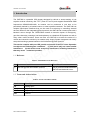
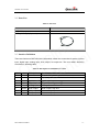
GMT100 User manual
GSM/GPRS/GPS Tracker
GMT100
User Manual
TRACGMT100UM001
Revision: 1.00
TRACGMT100UM001
http://www.queclink.com
[email protected]
GMT100 User manual
Document Title
GMT100 User Manual
Version
1.00
Date
2011-11-12
Status
Release
Document Control ID
TRACGMT100UM001
k
n
i
l
l
c
a
i
e
t
u
n
Q fide
n
o
C
General Notes
Queclink offers this information as a service to its customers, to support application and
engineering efforts that use the products designed by Queclink. The information provided
is based upon requirements specifically provided to Queclink by the customers. Queclink
has not undertaken any independent search for additional relevant information, including
any information that may be in the customer’s possession. Furthermore, system validation
of this product designed by Queclink within a larger electronic system remains the
responsibility of the customer or the customer’s system integrator. All specifications
supplied herein are subject to change.
Copyright
This document contains proprietary technical information which is the property of Queclink
Limited., copying of this document and giving it to others and the using or communication
of the contents thereof, are forbidden without express authority. Offenders are liable to the
payment of damages. All rights reserved in the event of grant of a patent or the
registration of a utility model or design. All specification supplied herein are subject to
change without notice at any time.
Copyright © Shanghai Queclink Wireless Solutions Co., Ltd. 2011
TRACGMT100UM001
-2-
GMT100 User manual
Contents
1. Introduction ................................................................................................................................... 7
1.1. Reference............................................................................................................................. 7
1.2. Terms and Abbreviations ..................................................................................................... 7
2. Product Overview ......................................................................................................................... 8
2.1. Appearance .......................................................................................................................... 8
2.2. Parts List.............................................................................................................................. 9
2.3. Interface Definition ............................................................................................................. 9
3. Getting Started ............................................................................................................................ 10
3.1. Installing a SIM Card ........................................................................................................ 10
3.2. Reset Key .......................................................................................................................... 11
3.3. USB connector .................................................................................................................. 11
3.4. Power Connection ............................................................................................................. 11
3.5. Ignition Detection.............................................................................................................. 12
3.6. Digital Inputs ..................................................................................................................... 12
3.7. Analog Inputs .................................................................................................................... 13
3.8. Digital Outputs .................................................................................................................. 13
3.9. Cut Relay Output............................................................................................................... 14
3.10. Device Status LED .......................................................................................................... 15
k
n
i
l
l
c
a
i
e
t
u
n
Q fide
n
o
C
TRACGMT100UM001
-3-
GMT100 User manual
Table Index
TABLE 1: GMT100 PROTOCOL REFERENCE .................................................................................... 7
TABLE 2: TERMS AND ABBREVIATIONS.......................................................................................... 7
TABLE 3: PART LIST ............................................................................................................................. 9
TABLE 4: DESCRIPTION OF GMT100 USER CABLE........................................................................ 9
TABLE 5: ELECTRICAL CHARACTERISTICS OF IGNITION DETECTION ................................. 12
TABLE 6: ELECTRICAL CHARACTERISTICS OF THE DIGITAL INPUTS ................................... 12
TABLE 7: ELECTRICAL CHARACTERISTICS OF DIGITAL OUTPUT .......................................... 13
TABLE 8: DEFINITION OF DEVICE STATUS AND LED ................................................................. 16
k
n
i
l
l
c
a
i
e
t
u
n
Q fide
n
o
C
TRACGMT100UM001
-4-
GMT100 User manual
Figure Index
FIGURE 1.
APPEARANCE OF GMT100 ......................................................................................... 8
FIGURE 2.
SIM CARD INSTALLATION ....................................................................................... 10
FIGURE 3.
TYPICAL POWER CONNECTION............................................................................. 11
FIGURE 4.
TYPICAL IGNITION DETECTION ............................................................................ 12
FIGURE 5.
TYPICAL DIGITAL INPUT CONNECTION .............................................................. 13
FIGURE 6.
TYPICAL ANALOG INPUT CONNECTION ............................................................. 13
FIGURE 7.
TYPICAL CONNECTION WITH RELAY .................................................................. 14
k
n
i
l
l
c
a
i
e
t
u
n
Q fide
n
o
C
FIGURE 8.
GMT100 LED ON THE CASE ..................................................................................... 15
TRACGMT100UM001
-5-
GMT100 User manual
Revision History
Revision
Date
Author
Description of change
V1.0.0
2011-11-12
Lei
Initial
k
n
i
l
l
c
a
i
e
t
u
n
Q fide
n
o
C
TRACGMT100UM001
-6-
GMT100 User manual
1. Introduction
The GMT100 is a powerful GPS locator designed for vehicle or asset tracking. It has
superior receiver sensitivity, fast TTFF (Time to First Fix) and supports Quad-Band GSM
frequencies 850/900/1800/1900, its location can be monitored in real time or be
periodically tracked by a backend server or other specified terminals. The GMT100 has
multiple input/output interfaces that can be used for monitoring or controlling external
devices. Based on the integrated @Track protocol, the GMT100 can communicate with a
backend server through the GPRS/GSM network to transfer reports of Emergency,
geo-fence boundary crossings, low backup battery or scheduled GPS position as well as
many other useful functions. Users can also use GMT100 to monitor the status of a
vehicle and control the vehicle by its external relay output. System Integrators can easily
setup their tracking systems based on the full-featured @Track protocol.
This device complies with part 15B, part 22 and part 24 of the FCC rules. Operation
is subject to the following two conditions:
(1) this device may not cause harmful
interference
(2) this device must accept any interference, including interference
that may cause undesired operation.
k
n
i
l
l
c
a
i
e
t
u
n
Q fide
n
o
C
1.1. Reference
Table 1: GMT100 Protocol Reference
SN
Document name
Remark
[1]
GMT100 @Track Air Interface Protocol
The air protocol interface between
GMT100 and backend server.
1.2. Terms and Abbreviations
Table 2: Terms and Abbreviations
Abbreviation
Description
AIN
Analog Input
DIN
DOUT
GND
Digital Input
Digital Output
Ground
TRACGMT100UM001
-10-
GMT100 User manual
2. Product Overview
2.1. Appearance
k
n
i
l
l
c
a
i
e
t
u
n
Q fide
n
o
C
Figure 1.
TRACGMT100UM001
Appearance of GMT100
-10-
GMT100 User manual
2.2. Parts List
Table 3: Part List
Name
Picture
GMT100 Locator
mm
DATA_CABLE_M (Optional)
k
n
i
l
l
c
a
i
e
t
u
n
Q fide
n
o
C
2.3. Interface Definition
There are 8 wires on GMT100 User Cable which contain the connection for power, ignition
input, digital input, analog input, siren output, cut output etc. The user cable’s definition
are shown in following table.
Table 4: Description of GMT100 User Cable
Index
Colour
Description
Comment
1
Red
Power
External DC power input, 8-32V
2
Black
Ground
System ground, connect to the vehicle’s frame directly
3
White
Ignition
Ignition input, positive trigger
4
Blue
Digital input
Digital input, negative trigger
5
Green
Analog input
Analog input, 0-32V
6
Brown
Siren output
Siren output, high end
7
Yellow
Relay ouput1
Internal relay output1.
8
Yellow
Relay ouput2
Internal relay output2
TRACGMT100UM001
-9-
GMT100 User manual
3. Getting Started
3.1. Installing a SIM Card
Step 1:
Step 2:
Step 3:
Remove the cover by screwdriver.
Make sure the contact area is facing down, insert the SIM into the slot.
Install the SIM card cover.
k
n
i
l
l
c
a
i
e
t
u
n
Q fide
n
o
C
Figure 2.
SIM Card Installation
3.2. Switch the set on/off
There are two methods to Power on GMT100:
- GMT100 external power turned on.
- Connect GMT100 to PC with user cable.
When the external power or USB cable power be removed,GMT100 will switch to internal
backup battery and keep on running. When internal backup battery is exhausted, GMT100
will give a report and then turn off.
Note:
1-External power and User USB power can be present at same time.
2-For USB port current limitation, when configuring GMT100 by user cable, please let
backup battery on using.
TRACGMT100UM001
-10-
GMT100 User manual
There is one method to turn off GMT100.
-Remove the external power and USB power.
-Press the reset key.
Note:
GMT100 PWR LED will off.
3.3. Reset Key
There is a reset key behind the SIM card cover. If the power wire is connected to vehicle
power, the system will reboot when the key is pressed; if the system is powered by the
backup battery and the power wire is not be connected to vehicle power, the system will
shutdown when the key is pressed.
Note:
When you finished the firmware upgrade, please press the reset key to reboot the system
before configuring the terminal.
k
n
i
l
l
c
a
i
e
t
u
n
Q fide
n
o
C
3.4. USB connector
There is a USB connector on GMT100 which is beside the SIM card. With the USB
connector and the DATA_CABLE_M, user can configure the system or download
firmware. As long as the DATA_CABLE_M is plugged in, the system will boot.
3.5. Power Connection
The red wire is power wire and the black wire is ground wire. The input voltage range for
this device is from 8V to 32V. The device is designed to be installed in vehicles that
operate on 12V or 24V systems without the need for external transformers.
Figure 3.
TRACGMT100UM001
Typical Power Connection
-12 -
GMT100 User manual
3.6. Ignition Detection
Table 5: Electrical Characteristics of Ignition Detection
Logical State
Electrical State
Active
5.0V to 32V
Inactive
0V to 3V or Open
k
n
i
l
l
c
a
i
e
t
u
n
Q fide
n
o
C
Figure 4.
Typical Ignition Detection
The white wire is used for ignition detection. It is strongly recommended to connect this
wire to ignition key “RUN” position as shown up.
An alternative to connecting to the ignition switch is to find a non permanent power source
that is only available when the vehicle is running. For example the power source for the
FM radio.
Ignition signal can be configured to start transmitting information to backend server when
ignition is on; and enter power saving mode when ignition is off.
3.7. Digital Inputs
There is a general purpose digital input which is the blue wire on GMT100 User Cable,
and it is a negative trigger. The digital input is recommended to support panic button
function.
Table 6: Electrical Characteristics of the digital inputs
Logical State
Electrical Characteristics
Active
0V to 0.8V
Inactive
Open
The following diagram shows the recommended connection of the digital input.
TRACGMT100UM001
-12 -
GMT100 User manual
k
n
i
l
l
c
a
i
e
t
u
n
Q fide
n
o
C
Figure 5.
Typical Digital Input Connection
3.8. Analog Inputs
There is an analog input which is the green wire on GMT100 User Cable, and the analog
input voltage range is from 0 to 32V. The following diagram shows the recommended
connection.
Figure 6.
Typical Analog Input Connection
3.9. Digital Outputs
There is an output which is the brown wire on GMT100 User Cable. This output is used to
drive a siren and the maximum drive current is 750mA. When the siren output is enabled,
the voltage on the siren output is determined by the system power level, if the system
power is 12V, then the siren output voltage is 12V.
Table 7: Electrical Characteristics of Digital Output
Logical State
Electrical Characteristics
Active
<1V
TRACGMT100UM001
-12 -
GMT100 User manual
Inactive
Open drain
k
n
i
l
l
c
a
i
e
t
u
n
Q fide
n
o
C
Figure 7.
Typical Connection with Relay
3.10. Cut Relay Output
There is a built-in cut relay on GMT100, and it is a NO type relay which maximum
switching voltage is 16VDC and maximum continuous current is 30A. On GMT100 user
cable one 18AWG yellow wire is connected to the cut relay NO contact and the other
18AWG yellow wire is connected to the cut relay COM contact. In certain instances the
two wires will be connected together.
TRACGMT100UM001
-12 -
GMT100 User manual
3.11. Device Status LED
k
n
i
l
l
c
a
i
e
t
u
n
Q fide
n
o
C
Figure 8.
TRACGMT100UM001
GMT100 LED on the Case
-12 -
GMT100 User manual
Table 89: Definition of Device status and LED
LED
Device status
LED status
GSM
(note1)
Device is searching GSM network
Fast flashing
(Note3)
Device has registered to GSM network.
Slow flashing
(Note4)
SIM card needs pin code to unlock.
ON
GPS chip is powered off
OFF
GPS sends no data or data format error.
Slow flashing
GPS chip is searching GPS info.
Fast flashing
GPS chip has gotten GPS info.
ON
No external power and internal battery voltage is
lower than 3.35V.
OFF
No external power and internal battery voltage is
below 3.5V.
Slow flashing
External power in and internal battery is charging
Fast flashing
External power in and internal battery is fully
charged
ON
GPS
(note 2)
k
n
i
l
l
c
a
i
e
t
u
n
Q fide
n
o
C
PWR
(note 2)
Note:
1 - GSM LED cannot be configured.
2 - GPS LED and PWR LED can be configured to turn off after a period of time using the
configuration tool
3 - Fast flashing is about 60ms ON/ 780ms OFF
4 - Slow flashing is about 60ms ON/ 1940ms OFF
TRACGMT100UM001
-12 -