1
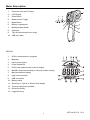
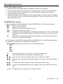
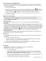
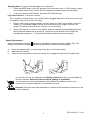
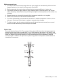
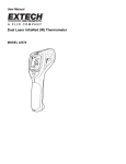
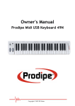
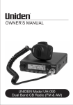
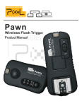
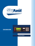
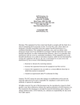
USER MANUAL Dual Laser InfraRed (IR) Thermometer MODEL 42570 Introduction Congratulations on your purchase of the Model 42570 IR Thermometer. This Infrared thermometer ° ° measures and displays non-contact temperature readings up to 3992 F/2200 C (certified to ° ° 2000 F/1100 C). At 50”, built-in dual lasers converge to 1” target spot to insure accurate targeting and temperature measurement. Advanced features include a USB PC interface and software, 100ms response time, Max/Min/Ave/Diff displays adjustable emissivity and High/Low alarms. Proper use and care of this meter will provide years of reliable service. Safety Use extreme caution when the laser pointer is on Do not point the beam toward anyone's eye or allow the beam to strike the eye from a reflective surface Do not use the laser near explosive gases or in other potentially explosive areas 2 42570-en-GB_V1.6 12/14 Meter Description 1. IR sensor and Laser Pointers 2. LCD Display 3. Down Button 4. Measurement Trigger 5. Mode Button 6. Battery compartment 7. Backlight/Laser Button 8. Up Button 9. Type K thermocouple input (side) 1 9 10 3 8 7 2 4 5 6 10. USB port (side) DISPLAY 1. SCAN, measurement in progress 2. Bargraph 3. Laser pointer active 4. Power locked ON 5. HOLD, last measurement locked in display 6. Max/Min temperature display or memory location display 7. Main temperature display 8. High/ Low limit alarm 9. USB connection 10. Battery status 11. Emissivity or Type K or Stored value display 12. Thermocouple probe installed 13. Emissivity setting 14. Logged memory 3 42570-en-GB_V1.6 12/14 Operating Instructions IR Temperature Measurements 1. Hold the meter by its handle and point it toward the surface to be measured. 2. Pull and hold the trigger to turn the meter on and begin testing. “SCAN” and the temperature reading will appear on the large display. The upper and lower sub-displays will indicate values/settings previously used. 3. Release the Trigger and the reading will hold for approximately 7 seconds (“HOLD” will appear on the LCD) after which the meter will automatically shut off. The only exception to this is if the LOCK mode is set to ON. The MODE button options With the trigger pulled (SCAN displayed), Press the MODE button to view and scroll through: MAX : Maximum value measured MIN: Minimum value measured DIF: Difference between the Max and Min values AVG: Average of the measured values LOG: A memory location is displayed in the small upper display and the value in that location is displayed in the small lower display. Press the ▲ or ▼ buttons to scroll through the locations. TK: With a Type K thermocouple probe connected to the meter, the probe temperature is displayed in the small lower display. With the trigger released (HOLD displayed), Press the MODE button to scroll through and access the following. The selected item is indicated by a blinking icon. Recorded data: (Press the ▲ or ▼ button to scroll through and view) MAX MIN DIF AVG LOG ε= Emissivity (blinking ε=). Press the ▲ or ▼ button to set the value. Lock mode. Press the ▲ or ▼ buttons to select ON or OFF. High alarm ON or OFF (blinking H). Press the ▲ or ▼ button to select. High alarm value adjustment (blinking H and value. ). Press the ▲ or ▼ button to set the Low alarm ON or OFF (blinking L). Press the ▲ or ▼ button to select. Low alarm value adjustment (blinking L and value. ). Press the ▲ or ▼ button to set the °C or °F Temperature units. Press the ▲ or ▼ button to select. 4 42570-en-GB_V1.6 12/14 Dual Laser Pointer and Backlight Button The dual laser pointers are designed to cross at a distance of 50” (76cm). The spot size at this distance is a 1” diameter and this is the recommended distance to target for most measurements. To turn the lasers on/off: 1. Press and Hold the Trigger ). Either the 2. While SCAN is on the display, press and release the backlight/laser button ( backlight or laser pointers will change status (On/Off). Repeat this until the desired conditions are set. The laser icon will appear in the LCD when the laser function is enabled. 3. The status of the functions will be stored in memory and will remain as the default “turn-on” condition until changed. High and Low Alarm Feature When either programmed alarm (high or low) point is reached the meter will alert the user via an audible beep and a blinking LCD display icon. The alarm limit is set and the feature is enabled/disabled using the MODE button. The setting is stored and memory and will remain as the “turn-on” condition until changed. Temperature Units The temperature units can be set to °F or °C. The selection is made using the MODE button. Lock feature The LOCK feature disables the Auto Power Off feature for the period of use when selected. The feature is useful for long term temperature monitoring and hands free use. The meter will revert to auto power off if the trigger is pressed during a locked scan. The selection is made using the MODE button. Turn on the 42570 by pressing the trigger. Once on, release the trigger and press and hold the MODE button until the LOCK icon ( ) appears. Press the arrow key (▼) until the display says ON. Press the trigger once and the meter will stay on until the trigger is pressed again. Over-range Indication If the temperature measurement exceeds the specified temperature range, the thermometer will display dashes in place of a temperature reading. USB Function The supplied software and cable are used to transmitt the IR and Type K measurement data to a PC via USB. To Turn-on or Shut-off the USB function: 1. With MAX, MIN, DIF, or AVG displayed, press the LIGHT/LASER button until “USB” sign appears in the right lower corner of the LCD. USB is active. 2. Press the LIGHT/LASER button again until “USB” disappears. The USB function is off. Refer to the help file in the software for operational details. Data Logger Storing Data: The thermometer is capable of storing up to 100 data points. Infrared: To store data from an infrared reading, 1. Pull and Hold the trigger 2. Press the MODE button until LOG appears in the lower left corner of the display; a log location number will be displayed. If no temperature has been recorded in the displayed LOG location, 4 dashes will appear in the lower right corner. 3. Aim the unit at the target area you want to record, and press the laser/backlight button. The recorded temperature will appear in the lower right corner. 4. To select another log location, press the up and down keys. 5 42570-en-GB_V1.6 12/14 Recalling Data: To recall stored data after the unit shuts off, 1. Press the MODE button until LOG appears in the lower left corner. A LOG location number will be shown below LOG, and the stored temperature for that location will be display. 2. To move to another LOG location, press the UP and Down keys. Log Clear Function: To clear the memory, The “Log clear” function allows you to quickly clear all logged data points. This function can only be used when the unit is in the LOG mode. 1. While in LOG mode, press the trigger, and then press the “down” arrow button until LOG location “0” is displayed. Note: This can only be done when the trigger is pulled. LOG location “0”cannot be accessed, by using the “up” arrow button. 2. When LOG location “0” shows in the display, press and release the laser/backlight button, then press and release the up arrow key. A tone will sound, and the LOG location will automatically change to “1”, signifying that all data locations have been cleared. Battery Replacement When the low battery symbol appears on the display, replace the meter’s battery (9V). The battery compartment is located behind the panel that surrounds the meter’s trigger. a) b) c) Press the release button (1) and swing (2) the door out from the handle Replace the 9V battery Close the door and press on the door at point (3) to engage the latch with an audible click. 2 1 3 You, as the end user, are legally bound (Battery ordinance) to return all used batteries and accumulators; disposal in the household garbage is prohibited! You can hand over your used batteries / accumulators at collection points in your community or wherever batteries / accumulators are sold! Disposal: Follow the valid legal stipulations in respect of the disposal of the device at the end of its lifecycle 6 42570-en-GB_V1.6 12/14 IR Measurement Notes 1. The object under test should be larger than the spot (target) size calculated by the field of view diagram (printed on the side of the meter and in this guide). 2. Before measuring, be sure to clean surfaces that are covered with frost, oil, grime, etc. 3. If an object's surface is highly reflective, apply masking tape or flat black paint to the surface before measuring. Allow time for the paint or tape to adjust to the temperature of the surface it is covering. 4. Measurements are not possible through visibly transparent materials, such as glass. 5. Steam, dust, smoke, etc. can obscure measurements. 6. The meter automatically compensates for deviations in ambient temperature. However, it can take up to 30 minutes for the meter to adjust to extremely wide changes. 7. To find a hot spot, aim the meter outside the area of interest then scan across (in an up and down or side to side motion) until the hot spot is located. Field of View The meter’s field of view is 50:1. For example, if the meter is 50 inches from the target (spot), the diameter of the target must be greater than 1 inch. Other distances are shown in the field of view diagram. Measurements should normally be made as close as possible to the 1” spot distance. The meter can measure from longer distances, but the measurement may be affected by external sources of light. In addition, the spot size may be so large that it encompasses surface areas not intended to be measured. @250cm 5cm @100” 2” @125cm 2.5cm @50” 1” @63cm 1.25cm @25” 0.5” 7 42570-en-GB_V1.6 12/14 Specifications o Range o o o -50 to 2200 C (-58 to 3992 F)(typical spec only >1000 C/1832 F) o o o o Resolution 0.1 < 1000 , 1 ≥ 1000 Accuracy -50°C to -23°C (-58°F to -10°F) ±7°C/14°F (Typical) -23°C to -2°C (-10°F to 28°F) ±4°C/8°F -2°C to 94°C (28°F to 200°F) ±2.5°C/4.5°F 94°C to 204°C (200°F to 400°F) ±(1.0%rdg + 1°C/2°F) 204°C to 426°C (400°F to 800°F) ±(1.5%rdg + 1°C/2°F) 426°C to 1000°C (800°F to 1832°F) ±(3%rdg +1°C/2°F) 1000°C to 2200°C (1832 to 3992°F) ±(5%rdg +2°C/4°F)(typical only) Note: Accuracy is specified for the following ambient temperature range: 23 to 25°C (73 to 77°F) Emissivity 0.10 to 1.00 adjustable Field of View D/S = Approx. 50:1 ratio (D = distance; S = spot or target) Laser pointer Dual, Class 2 laser < 1mW power; Wavelength is 630 to 670nm IR Spectral response 8 to 14 m (wavelength) Repeatability ± 0.5% of reading or ± 1 C (1.8 F) whichever is greater o o Thermocouple Thermometer (Type K) Range -50 to 1370°C(-58°F to 2498°F) Resolution 0.1 °C(0.1°F)<1000, 1°C(1°F)>1000 Accuracy -50 to 1000°C (-58 to 1832°F): ± 1.5% of reading + 3°C (±5°F) 1000 to 1370°C (1832°F to 2498°F): ± 1.5% of reading + 2°C (±3.6°F) General Specifications Display Backlit LCD display with function indicators Response time 100ms Over range indication “---------“ Operating Temperature 0 C to 50 C (32 F to 122 F) o o o o Operating Humidity 10% to 90%RH operating, <80%RH storage. Storage Temperature -10 to 60 C (14 to 140 F) Power Supply 9V battery o o Automatic Power Off 7 seconds, with LOCK to disable Weight 320g (11.3 oz.) Dimensions 204 x 155 x 52mm (8 x 6.1 x 2”) Copyright © 2014 FLIR Systems, Inc. All rights reserved including the right of reproduction in whole or in part in any form ISO‐9001 Certified www.extech.com 8 42570-en-GB_V1.6 12/14