1
PT630 Operation Guide
Page 1 of 41
______________________________________________________
PT630 Portable Terminal
Operation Guide
V1.0
PT630 Operation Guide
Page 2 of 41
______________________________________________________
CHAPTER 1.
INTRODUCTION ........................................................................................................................3
1.1
1.2
PROGRAMMING ................................................................................................................................................3
SUBSYSTEMS ....................................................................................................................................................4
1.2.1
Keypad Subsystem................................................................................................................................4
1.2.2
Display Subsystem................................................................................................................................4
1.2.3
Serial Port Subsystem...........................................................................................................................5
1.2.4
Real Time Clock Subsystem..................................................................................................................5
1.2.5
Bar Code Input Port.............................................................................................................................5
1.3
DIAGNOSTICS AND POWER-ON-TEST ...............................................................................................................5
CHAPTER 2.
2.1
2.2
2.3
SYSTEM SOFTWARE ORGANIZATION ...............................................................................6
APPLICATION MODULE .....................................................................................................................................6
KERNEL MODULE.............................................................................................................................................6
OPERATION FLOW ............................................................................................................................................7
CHAPTER 3.
OPERATING MODES.................................................................................................................9
3.1
KEYBOARD MODES --- USING PT630’S KEYBOARD .........................................................................................9
3.1.1
NORMAL mode ..................................................................................................................................10
3.1.2
COMMAND mode ..............................................................................................................................10
3.1.3
ALPHA mode......................................................................................................................................10
3.2
PT630 MODES OF OPERATION .......................................................................................................................11
3.2.1
Ready Mode........................................................................................................................................11
3.2.2
User Mode..........................................................................................................................................11
3.2.3
Supervisor Mode ................................................................................................................................17
CHAPTER 4.
4.1
4.2
4.3
INTRODUCTION.........................................................................................................................................28
FEATURES...................................................................................................................................................29
I/O PORTS ......................................................................................................................................................29
4.2.1
The PT630 has three interface ports:.................................................................................................29
4.2.2
Scanner...............................................................................................................................................29
4.3.3
PT630 CHARGING/COMMUNICATION CRADLE ..........................................................................30
CHAPTER 5.
5.1
5.2
HARDWARE OVERVIEW.......................................................................................................28
COMMUNICATION .................................................................................................................31
INSTALLATION..........................................................................................................................................31
DOWNLOADING AND UPLOADING.......................................................................................................33
5.2.1
Downloading a Jobgen Pro application from Host to PT630............................................................34
5.2.2
Uploading Jobgen Pro files from PT630 to HOST ............................................................................34
5.2.3
Downloading a file from Host to PT630 using the Kermit Server .....................................................35
5.2.4
Uploading files from PT630 to HOST using the Kermit Server .........................................................36
CHAPTER 6.
TROUBLESHOOTING .............................................................................................................37
CHAPTER 7.
POWER SOURCES ...................................................................................................................39
7.1
7.2
7.3
7.4
MAIN/BACKUP BATTERY REPLACEMENT AND INSTALLATION...................................................40
MAIN POWER BATTERY CHARGING WITH AC/DC ADAPTOR (REGULAR/NORMAL CHARGE)........41
MAIN BATTERY CHARGING WITH CRADLE.......................................................................................41
MAIN BATTERY STORAGE & SAFETY PRECAUTIONS .....................................................................42
PT630 Operation Guide
Page 3 of 41
______________________________________________________
Chapter 1.
Introduction
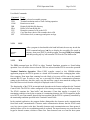
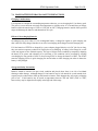
The PT630 is a programmable and flexible data collection device that can be utilized in a variety of
data acquisition applications. It can be used as a portable data entry device and it can also be used as
a programmable dedicated computer that receives and runs application programs downloaded from a
host computer.
The PT630 is controlled by a 16-bit INTEL 8088 compatible microprocessor, and has a 256K user
programmable FLASH MEMORY that includes a rich set of DOS functions and device drivers for
application development, including bar code decoding, display, keypad, communications, and real
time clock/calendar.
PT630 BLOCK DIAGRAM
┌────────┐
│Lithium │
┌─────────┐
│Battery │
│ 128x64 │
└───┬────┘
│ bit map │
┌────┴─────┐
├─────────┤
┌──┴────┐ ┌──┴───┐
│ Graphic │
┌──────────┐
┌───────┐ │RAM
│ │ Real │
│ LCD
│
│ 256K
│
│16-bit │ │512K- │ │ Time │
│ Driver │
│ Flash ROM│
│ CPU
│ │ 4.5MB │ │ Clock│
└───┬─────┘
└────┬─────┘
└───┬───┘ └──┬────┘ └──┬───┘
│
│
│
│
│
═══════════════════════╧╤═════════════╧═╤═══════════╧════╤════╧══════════╧════
│
│
│
╔═╦═╦═╗
┌───┴────┐
┌────┴─────┐
┌────┴─┬────────────┐
Keypad ╠═╬═╬═╬═══╡ Key
│
│ RS-232 │
│ Bar │ Integrated │
╠═╬═╬═╣
│ Matrix │
│ Serial │
│ Scan │ Laser Diode│
╚═╩═╩═╝
└────────┘
└──────────┘
└──────┴────────────┘
The PT630 can be purchased with 512K, 1.5MB, 2.5MB, 3.5MB or 4.5M on-board RAM. All
RAM memory is powered by the main Li-ion battery and a back-up lithium battery, which retains
the data stored in RAM and real time clock when the main battery is drained. The PT630 has a
128x64 pixel backlit graphic LCD display, an integral 27-key keypad, a built-in bar code laser
scanner/CCD module and an RS-232 serial port for data communication with a host PC.
1.1 Programming
The PT630 system kernel includes three basic modules: 1. Device driver, 2 File manager and
3.DOS manager. The PT630 terminal can be programmed using an E-PROM resident application
program called FormCaching, a Windows-based, high-level application generator JobgenPlus,
Microsoft C, Borland C, Turbo C, Turbo Pascal and IBM PC macro assembler. The ROM based
firmware of the terminal provides emulated MS/DOS function calls. The programmer can design
the application programs by calling those functions just like in a DOS environment. The calling
and parameter passing conventions are compatible to that of MS/DOS and the programs are in the
EXE format. Programming details are included in the PT630 programming manual in this binder.
PT630 Operation Guide
Page 4 of 41
______________________________________________________
The intelligence level of the terminal is determined by the configuration of the FormCaching
application or the downloaded program generated by JobgenPlus or supported language compiler.
Once the program has been started up, the terminal operates as a stand-alone unit, storing
transaction data in the RAM disk area or linked to a host/personal computer.
1.2 Subsystems
The following describes several subsystems and related I/O interface functions, the DOS manager
and file manager functions. Detailed calling process is explained in the Programming Reference
Guide included in this binder.
1.2.1
Keypad Subsystem
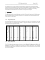
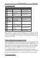
The keypad subsystem scans the key matrix, converts the scan code to its associated key value and
stores the value in the keyboard input buffer for program utilization. The table below shows
hexadecimal values assigned to each key.
KEY
CLR
ENTER
↓
↑
SP
!
#
$
%
&
*
+
,
1.2.2
VALUE
08H
0DH
10H
11H
12H
13H
20H
21H
23H
24H
25H
26H
2AH
2BH
2CH
KEY
.
/
0
1
2
3
4
5
6
7
8
9
:
;
VALUE
2DH
2EH
2FH
30H
31H
32H
33H
34H
35H
36H
37H
38H
39H
3AH
3BH
KEY
=
?
@
A
B
C
D
E
F
G
H
I
J
K
L
VALUE
3DH
3FH
40H
41H
42H
43H
44H
45H
46H
47H
48H
49H
4AH
4BH
4CH
KEY
M
N
O
P
Q
R
S
T
U
V
W
X
Y
Z
[
VALUE
4DH
4EH
4FH
50H
51H
52H
53H
54H
55H
56H
57H
58H
59H
5AH
5BH
KEY
Y
Z
[
\
]
F1
F2
F3
F4
F5
F6
F7
F8
EXIT
VALUE
59H
5AH
5BH
5CH
5DH
86H
87H
88H
89H
8AH
8BH
8CH
8DH
84H
Display Subsystem
The PT630 display subsystem supports a character oriented 8-line by 20-character or 4-line by 16character LCD display. The origin (0,0) is always at the top-left hand corner. This subsystem
provides the program interface functions to display characters, set cursor position, get cursor position
and clear screen display.
PT630 Operation Guide
Page 5 of 41
______________________________________________________
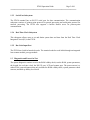
1.2.3
Serial Port Subsystem
The PT630 terminal has an RS-232 serial port for data communication. The communication
subsystem consists of point-to-point protocol for general processing and multi-point protocol for
network processing. The PT630 also supports a built-in Kermit server for point-to-point
communication.
1.2.4
Real Time Clock Subsystem
This subsystem allows users to set and obtain system date and time from the Real Time Clock
Integrated Circuit (IC) in the PT630.
1.2.5
Bar Code Input Port
The PT630 has a built-in barcode decoder. The terminal reads bar code labels through an integrated
laser scanner module, pen type module.
1.3 Diagnostics and Power-On-Test
The system diagnostic routines exercise the ROM validity check, test the RAM, system parameters,
the keypad, the real time clock, the RS-232 port, LCD and scanner port. The power-on-test is a
subset of the system diagnosis that only includes the ROM validity check, system parameter check
sum test, and back-up battery level check.
PT630 Operation Guide
Page 6 of 41
______________________________________________________
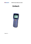
Chapter 2. System Software Organization
The PT630 system software is organized into two modules: the kernel module and the application
module (see diagram below).
MODULE ORGANIZATION
┌──────────────────────────────────────────────────────────────────┐
│
┌───────────┐
|
┌──────────────────┐
│
│ APPLICATION │Terminal
│
|
│ Downloadable
│
│
│ MODULE
│module
│
|
│ Application
│
│
│
└───────────┘
|
└──────────────────┘
│
│
┌───────────┐
|
┌──────────────────┐
│
│
│Workstation│
|
│ Downloadable
│
│
│
│module
│
|
│ Application
│
│
│
└───────────┘
|
└──────────────────┘
│
│
┌───────────┐
|
┌──────────────────┐
│
│
│User-device│
|
│ Downloadable
│
│
│
│module
│
|
│ Application
│
│
│
└───────────┘
|
└──────────────────┘
│
│
RESIDENT APPLICATIONS
|
TRANSIENT APPLICATION
│
│
|
│
╞══════════════════════════════════════════════════════════════════╡
│ KERNEL
┌──────────┐
┌────────────┐
┌──────────┐
│
│ MODULE
│ SCAN_INT │
│ KEYPAD_INI │
│ COM_INI │
│
│
└──────────┘
└────────────┘
└──────────┘
│
│
┌──────────┐
┌────────────┐
│
│
│ EXEC
│
│ LOADER
│
│
│
└──────────┘
└────────────┘
│
│
┌──────────┐
┌────────────┐
┌──────────┐
│
│
│ DOS
│
│ FILE
│
│ COM
│
│
│
│ Manager │
│ Manager
│
│ Manager │
│
│
└──────────┘
└────────────┘
└──────────┘
│
└──────────────────────────────────────────────────────────────────┘
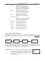
2.1 Application Module
Although applications run on the PT630 are classified into resident and transient categories, the
PT630 operation can not decipher the difference between them. The only difference is the location of
the executable files. For resident applications, the Job Scheduling EXEC "jumps" to the entry point
in the EPROM and begins execution. For transient applications EXEC "loads" the executable file
from the RAM file into the RAM memory and then begins execution.
2.2 Kernel Module
The PT630 kernel provides basic system services. The kernel module includes the DOS Manager,
File Manager, COM Manager and several interrupt service routines.
DOS Manager
The DOS manager emulates most MS DOS function calls to control PT630
peripherals and files.
FILE Manager
The File manager implements a DOS-like file subsystem to support essential file
operations.
PT630 Operation Guide
Page 7 of 41
______________________________________________________
COM Manager
The COM manager controls the communication link between the PT630 and the
host through a RS232 serial port.
LOADER
The function of the loader is identical to that of the MSDOS loader except for the
memory allocation/deallocation scheme being simplified. The loader's operations
are:
1.
2.
3.
4.
5.
6.
read .exe header
find enough memory for .exe
read binary into RAM
relocation based on RAM allocation
set up all registers
jump to the entry point
LCD Manager
The LCD manager handles the cursor positioning and graphic pattern display.
Two character pattern fonts are supported. PT630 can support both 6x8 font (20
column by 8 lines) and 8x16 font(16 column by 4 line).
EXEC
The EXEC is the job scheduler. It manages top-level operation flow of the PT630
system. The EXEC program is analogous to the COMMAND.COM program in
MS DOS-based machines.
2.3 Operation Flow
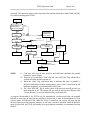
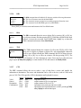
The EXEC program controls the PT630. When the portable terminal is powered up, EXEC performs
the power-on-test (POT). EXEC proceeds to verify if the PT630 should make a warm or cold
booting. A warm boot resets the system without clearing any RAM program or data files. Device
configurations preserve the same values as they had before the warm boot. On the other hand, a cold
boot will clear the RAM and initialize the PT630 to default values.
The PT630 is always testing its main and backup batteries. The LCD will display a warning message
when the test fails.
Power on Test
Test failure message
Main battery test
Backup battery test
"WARNING MAIN BATTERY LOW"
"WARNING LITHIUM BATTERY LOW"
When the main battery is low, a warning message will be displayed on the LCD when PT630 is
power on. For PT630, it can automatically detect battery status, a warning sign will be display on
battery icon on the upper side of LCD.
During the start-up process, EXEC also initializes the PT630 barcode scanner and RS232
communication port, and creates all dynamic data structures; e.g. keypad queue and COM buffer.
Once the initialization procedure has been completed, EXEC checks if a supervisor menu has been
PT630 Operation Guide
Page 8 of 41
______________________________________________________
requested. The supervisor menu can be requested if the operator holds down both [CMD] and []
keys while powering up the PT630.
POWER ON
Press [CMD] & [<]
simutaneously
while pressing [PWR]
YES
NO
<<START MENU >>
1.SUPERVISOR
2.WARM START
3.COLD START
YES
START FLAG
error?
NO
press [3]
press [2]
YES
SAVE NOT OK
error?
NO
press [1]
NO
RESUME?
YES
WARM START
Supervisor mode
Disabled?
WARNING !
DELETE ALL DATA
Are you sure?
(YES/NO)
NO
YES
AUTOEXEC.exe
existed?
System Recover
YES
run
AUTOEXEC.exe
SUPERVISOR mode
press
press
NO]
Yes]
NO
READY mode
COLD START
press [CMD] and
hold down for 2 seconds
USER mode
NOTE:
1)
2)
3)
4)
Cold start, will clear all data stored in the RAM and reinitialize the portable
terminal to system default.
There are two system flags, “Start” flag and “Save NOT OK” flag, which will be
verified each time the unit is turned on.
When the “Start” flag verification fails, it indicates that there is probably a
defective RAM chip or that the backup battery power is low. A data back up and
hardware diagnostics are recommended in these cases.
The “Save NOT OK” flag is used to check if the previous turn-off process was
made normally or not. The system will not return to the last turn-off point if the
“System Resume” is set to On when this flag verification fails.
A program downloaded to the PT630 may be automatically executed each time the portable
terminal is turned on. In order for the program to be auto-ran, it must be downloaded to PT630
with the name AUTOEXEC.EXE. When the PT630 is turned on, the system will scan the file
directory and execute the program, otherwise it will enter a mode of operation called the READY
mode. In this mode, the PT630 will standby for keypad-entered commands, or commands from the
Host PC.
PT630 Operation Guide
Page 9 of 41
______________________________________________________
Chapter 3. OPERATING MODES
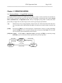
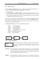
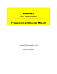
3.1 Keyboard Modes --- Using PT630’s keyboard
The keypad of PT630 consists of 27 rubber keys, the ⊙ key is used to switch on/off the unit and other 26
keys are used to control the unit and key in data. The use of keyboard is categorized to three modes: normal
mode, command mode, and alpha(betic) mode. All keys except ⊙ key may produce a sound (tone) when
pressed. Keys of upper four rows have larger size for easier key-pressing to input numbers.
[⊙
⊙]
When the unit is off, pressing the ⊙ key will turn on the unit. On the other hand, when the unit is
on it is needed to press and hold down the ⊙ key for about one second in order to turn the unit
off.
[CMD]
Pressing the [CMD] key sets the keyboard to Command mode. However pressing and holding
down the [CMD] key for two seconds in Ready mode will enter the User mode. In User mode,
users can invoke system commands by menu selection.
[CMD] then [Alpha]
In User mode or Supervisor mode, pressing the [CMD] key and then pressing
[ALPHA] key will exit from the current operation to the previous operation.
press [CMD]
press [CMD]
NORMAL
mode
press [ALPHA]
press [ALPHA]
press [CMD]
COMMAND
mode
press [ALPHA]
ALPHA
mode
PT630 Operation Guide
Page 10 of 41
______________________________________________________
NORMAL mode
Keyboard of the PT630 is initialized to normal mode after powered on. In
normal mode, the cursor is a block sign and the keyboard is mainly used to
input numeric data and use F1-F4 four function-keys. The keypad layout of
available keys in normal mode is shown on right picture.
3.1.1
Enter
→ key for next data search
← key for last data search
Clear
SPACE
3.1.2 COMMAND mode
Press [CMD] key sets the keyboard to command mode. In command mode,
the cursor type keeps same and the keyboard is mainly used to input special
characters, make hot-key function, and use F5-F8 four function-keys. The
keypad layout of available keys on command mode is shown on right picture.
There are three hot-key functions and the usage of each function is described
below.
LCD Backlit On/Off : Hit []Key to toggle between ON and Off.
LCD Contrast
:Press and hold down [] key to continuously
change from light to dark.
Buzzer Volume
: Hit [SP] key to toggle among Mid, Hight and
None
Backlit
Contrast
3.1.3 ALPHA mode
Press [ALPHA] key to toggle between normal mode and alpha mode of keyboard In alpha mode, the cursor is
an underscore sign and the keyboard is available to input upper case letters. In alpha mode, every numeric key
contains 3 characters individually. Pressing the key to choose among three available characters.
For example :
First press [ALPHA] to switch the system to alpha mode, the cursor type will be
changed from block to underscore
To enter ‘A’, hit [7] one time
To enter ‘B’, hit [7] twice.
To enter ‘C’, hit [7] three times.
PT630 Operation Guide
Page 11 of 41
______________________________________________________
3.2 PT630 Modes of Operation
There are three modes of operation in the PT630:
a. Ready Mode
b. User Mode
c. Supervisor Mode
3.2.1 Ready Mode
The Ready mode is the default resident operating mode. In the Ready mode the PT630 is configured
as a portable programmable device, and is capable of receiving files (Download) from or
transmitting files (Upload) to a Host PC. Data files or recorded information collected from the
PT630 are uploaded to the host whenever the host program is ready to receive the collected data.
Some applications may also require prepared data files (e.g. database information). These data files
are loaded to the PT630 in the same manner as application programs are downloaded. The PT630
carries out upload and download operations through its built-in RS232 port. The operator can later
select one of the executable applications to run in the portable terminal via the keypad or host
command sequence.
After the Warm Start, the PT630 enters the Ready mode and shows the Ready mode screen as
shown left. The first line indicates the model code and BIOS firmware version number. The second
line shows the size of the installed RAM. The third line shows the prompt, ">" which indicates that
the terminal passed the Power-on-test and is in the Ready mode of operation.
Ready Mode
User mode menu
PT630 V1.50
MEM 512 KB
Press and Hold down [cmd]
Key for two second
Press [CMD] then [Alpha]
1.RUN
3.COM
5.ERA
7.CPY
2.TER
4.DIR
6.TYP
8.SET
3.2.2 User Mode
The User Mode allows the operator to issue commands to the PT630. Pressing and holding down the
[CMD] key for two seconds while in the Ready Mode will invoke the User Mode (see figure
below). There are eight commands: 1.RUN, 2.TER, 3 COM, 4.DIR, 5. ERA, 6.TYP, 7.CPY, and
8.SET. Select the corresponding number, 1-8, or press [] and [] to move cursor then press [ENT]
to select and issue the desired command to the PT630. Pressing [CMD] then [Alpha] key will return
the system to the Ready Mode.
PT630 Operation Guide
Page 12 of 41
______________________________________________________
User Mode Commands:
Command
RUN
TER
COM
DIR
ERA
TYP
CPY
SET
3.2.2.1
Usage
Runs the selected executable program
Terminal emulation mode or Form Caching operation
Kermit server mode
Display RAM disk file directory
Delete a file from RAM disk
Dump the content of a file to the LCD
Copy data from a device/file to another device/file
Set real time clock, scanner type and power-on logo
RUN
< RUN PROGRAM >
Filename:
NULL
3.2.2.2
After a program is downloaded to the hand held unit, the user may invoke the
RUN command and press [→
→] key to display the executable files stored in
memory, then press [ENT] to run the program. Pressing [CMD] then [Alpha]
and then pressing any key will return the PT630 to the User Mode menu.
TER
The TER command puts the PT630 in either Terminal Emulation operation or FormCaching
operation. User will need to choose when the TER was selected and the PT630 execute the operation.
Terminal Emulation Operation. When EXEC transfers control to this EPROM-resident
application program, the PT630 operates as a dumb ASCII terminal while exchanging data with a
Host computer. Data input from scanning bar code labels or key-press will be sent to the portable
terminal RS-232 port. In order to carry out a successful file transfer, communication parameter
setting such as baud rate, data bits, parity, stop bits and flow control, must match the setting at the
Host end. Data received from the serial port is displayed on the LCD screen.
The functionality of the PT630 in terminal mode depends on the format configured in the Terminal
Control Table. The PT630 is either configured as free format processing or forms based processing.
The PT630 examines the "data buffer" and determines if host data transfer is required. If a
terminating condition exists by the reception of a terminating character, the PT630 outputs the buffer
to its RS232 port. Data transfer between the host machine and the PT630 is primarily controlled by
the terminating conditions specified in the Terminal Control Table.
In the terminal application, the program further distinguishes the character mode communication
from block mode communication. Character mode communication dictates that the PT630 sends
every key (one at a time) to the host. Normally character mode communication uses None protocol,
otherwise there will be an overwhelming protocol overhead. The input character may come from the
keypad or barcode scanner, whichever comes first. Data characters sent over from the host system
PT630 Operation Guide
Page 13 of 41
______________________________________________________
will always be displayed on the LCD screen. Host control commands, which have a special
command header (ESC), will not be displayed on the LCD. The host commands are interpreted by
the PT630 as they are received.
Block mode applications perform similar functions to character mode, except that the input
characters will not be sent to the host one character at a time. Instead the PT630 holds the data in its
internal buffer until a termination character is received. Specifying parameter linepage, lineterm, and
pageterm in the terminal control table programs the termination character. The PT630 allows at most
two termination characters.
FormCaching Operation. When EXEC transfers control to this EPROM-resident application
program, it allows the user to create a data entry application program by simply specifying field
prompt, type, length, input method and delimiter, etc. without having to write a comprehensive
application program. FormCaching is enabled or disabled while the PT630 is in the Supervisor mode
of operation.
3.2.2.3
COM
The COM command activates the PT630 Kermit server. Pressing [CMD] then [Alpha] returns the
PT630 to the User Mode of operation. The following list shows the available Kermit commands in
the Host/PC:
Command
Description
SEND program
Sends a file from the Host/PC to the PT630 and
stores it in the PT630's RAM disk.
GET data
Gets a collected data file from the PT630 to the Host/PC disk.
REMOTE DIR
Lists PT630 RAM disk file directory.
REMOTE DEL filename
Deletes a program or data file from the PT630 RAM disk.
BYE
Exit Kermit Mode
Before making use of the Kermit server, switch the PT630 to the Supervisor mode and set the PT630
communication parameters to match the host/PC system. See Section 3.2.3.1 Device Configuration.
PT630 Operation Guide
Page 14 of 41
______________________________________________________
3.2.2.4
DIR
The DIR command shows RAM disk file directory with the following information:
The list of file names stored in the RAM DISK.
The amount of memory assigned to executable programs (Execution Area).
The amount of free RAM DISK space left. (FREE DISK)
MYPRG.EXE
ITEM.DAT
<<END>>
2 File(s)
Press [ENT] to exit this screen and return to the User Mode menu.
3.2.2.5
ERA
The ERA command allows the user to delete file by pressing [] or [] key
to select an existence file then pressing [ENT]. When the selected file has been
deleted, it can not be recovered. Press [CMD] then [Alpha] key to abort the
ERA command and return to User Mode Menu.
< ERASE FILE >
Filename:
█
3.2.2.6
TYP
The TYP command dumps the contents of a file to the PT630's LCD. If the
user tries to display a program or binary file, only unintelligible characters
will be seen. When selecting the TYP command, the PT630 allows the user
using [] or [] key to select an existence file then pressing [ENT]. The
screen will display 160 (20 character x 8 line) characters at a time. Press any key to show the next
page or press [CMD] then [Alpha], to warm start the PT630 and return to the Ready Mode.
< TYPE FILE >
Filename:
█
3.2.2.7
CPY
The CPY command allows the user to make a copy of data from a source and transfer the
information to destination. The source and destination can be a file or devices, such as COM, serial
port or CON. The CON specifies LCD for destination and keyboard for source.
Valid
Source/
Destination
Combination
Source
file1
file1
file1
COM
CON
Destination
file2
COM
CON
file2
file2
Function
copy file1 to file2
output content of file1 to serial port
output content of file1 to LCD
input data from serial port and store in file2
input data from keyboard and store in file2, pressing [CMD]
then [Alpha] to end the data input
PT630 Operation Guide
Page 15 of 41
______________________________________________________
3.2.2.8
SET
<SYSTEM SETUP>
1.DATE & TIME
2.SCANNER
3.DISPLAY
4.KEYPAD
5.EXIT
3.2.2.8.1
The SET command allows the user to set system date-time, select type of bar
code scanner, assign laser module scanning method, enable double
verification and specify whether to show power-on logo. Select the
corresponding number, 1-4, to invoke a function. Pressing the [CMD] and
then the [Alpha] key returns the portable terminal to the User Mode menu.
DATE & TIME Set System Clock/Calendar
By selecting “1.DATE & TIME” in the SET menu, you can set the PT630 date and time. The date
and time can be used as the time stamp to be appended to an input data record DATE-TIME SETUP
by an application program. The second line shows the current system date in 1998/01/01
the format YYYY/MM/DD (year/month/day). For instance, 1998/01/01 08:00:00
indicates that date is January 1, 1996. If you want to reset the system date to
August 31, 1997, then enter [1],[9],[9],[7],[0],[8],[3],[1]. Or press the [ENT] key to skip the system
date setting.
The third line shows the current time. The setting method is similar to setting the date. The time is
expressed in the 24-hour system in the format HH:MM:SS (hours:minutes:seconds).
3.2.2.8.2
SCANNER
SCANNER
The bar code input interface of the PT630 is compatible to all major bar code
scanners that are available in the market including wand, CCD and laser diode
scanners. Use the [] key to toggle among ENABLE and DISABLE, then press
[ENT].
LASER TRIG MODE : User can select whether pen is activate to read barcode label by one
trigger/one scan or flash scan.
If it is set NORMAL, laser beam will be emitted to scan barcode and it will stop
laser beam after successfully scan barcode. User need to release trigger key and
then press again to scan next label.
If it is set to FLASH, user just press trigger and then release it, then scanner will
automatically scan barcode. When it successfully read a barcode, scanner will
continuously emit laser beam to read next label. User can press trigger again to
stop automatic scanning.
LASER AIM When PT630 is equipped with SE1200LR engine, user can use this setting to
activate aim beam before starting scanning barcode. It will be helpful for user to
focus target barcode label. Use the [] key to toggle among ENABLE and
DISABLE, then press [ENT].
VERIFICATION When label quality is not good, and then cause error decoding. You can
enable this function to let PT630 double verification input barcode. When it is set
ENABLE, PT630 read barcode label twice to compare if it read the same data.
PT630 Operation Guide
Page 16 of 41
______________________________________________________
3.2.2.8.3 DISPLAY
Enable/Disable whether to show the Power-on LOGO.
Power-on LOGO enabled is the default setting.
3.2.2.8.4 KEYPAD:
Setup up-case and low-case Alpha character input
User can define upper-case or lower-case input on Alpha mode.
PT630 Operation Guide
3.2.3
Page 17 of 41
Supervisor Mode
The PT630 Supervisor mode allows the user to configure and validate the PT630 hardware. To
switch the PT630 to the Supervisor mode of operation do the following:
1. Turn off the PT630.
2. Press and hold down the [CMD] and [
] keys simultaneously, then switch on the PT630 by
pressing the [⊙] key. The PT630 LCD first shows the ‘START MENU” where the user has
three (3) choices: 1.Enter the Supervisor mode, 2.Command the PT630 to execute a Warm Start,
3. Command the PT630 to execute a Cold Start.
After selecting 1, a password entry is requested from the user to prevent unauthorized users from
accidentally changing configuration parameters. The system will return to the Ready mode after 5
unsuccessful tries. The default password is “630”. The Supervisor mode menu will be shown on
LCD after the correct password is keyed-in.
The Supervisor Mode function lets the user set the following functions:
1. DEV:
Device Configuration
2. TERM:
Terminal Configuration
3. MEM:
Memory Configuration
4. FORM:
FormCaching Define
5. PWR:
Set Resume/Auto-Off/Alarm of program
6. PSWD:
Password Change
7. SYS: System Initialization, update BIOS
8. DIAG:
System Diagnostic
<START MENU>
1.SUPERVISOR
2.WARM START
3.COLD START
3.2.3.1
SUPERVISOR
MODE
PASSWORD:
1.DEV
3.MEM
5.PWR
7.INI
2.TERM
4.FORM
6.PSWD
8.DIAG
Device Configuration
<DEVICE CONFIG>
1.KEYPAD
2.SERIAL
3.BARCODE
When selecting the option "1.DEVICE", the LCD will offer the user 3
choices: 1) Set the keypad input Language setting, 2) Set the serial port
communication parameters, and 3) Enable/disable supported bar code
symbologies.
1.KEYPAD
The PT630 supports several international language setting. The default language
setting is ENGLISH. Press [] or [] to select different language setting. There
are Sweden/Finland, Danish, Spanish, Franch, German, and Italian. Press [ENT] to
confirm the setting and return to the previous manu.
2.SERIAL
The PT630 supports one RS232 port on flat 12 pin connector. Data can be
downloaded to and uploaded from the PT630 via the serial data communication
PT630 Operation Guide
Page 18 of 41
port. The communication parameters must be set correctly in order to
send/receive data via the RS232 port. Default setting for the serial port is 19200
bps,8 data bits, No parity, One stop bit
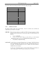
The settings for the communication parameters include:
Category
♦ Baud Rate
♦
♦
♦
♦
♦
♦
Length
Parity
Stop bits
Flow Control
Protocol
Address
Selection
150, 300, 600, 1200, 2400, 4800
9600, 19200, 38400, 57600.
7, 8
Even, Odd, None
1, 2
Xon/Xoff, CTS/RTS, None
MULTI, OFF (None)
A~Y, 0~6
PT630
Default
19200
8
None
1
None
MULTI
A
Press [] to select the setting, [ENT] to confirm the setting.
3.BARCODE when selecting Option 3. BARCODE in the Supervisor Mode, Device
Configuration menu, the LCD will display the BARCODE Setup as shown below.
<< BARCODE SETUP>>
CODE 39
ON
Press [] or [] to toggle between settings. Press [ENT] to set.
Setup decoding of PT630 supported bar code symbologies
Symbology
Code 39
Setup Category (default)
Enable/disable decoding (ON)
Enable/disable full ASCII (OFF)
Send/No-send Start/stop Character (NO SEND)
Enable/disable Check Digit Verification (OFF)
I 2 of 5
Enable/disable decoding (ON)
Enable/disable Check Digit Verification (OFF)
Codabar
Enable/disable decoding (ON)
Send/No-send Start/stop Character (SEND)
Enable/disable Check Digit Verification (OFF)
UPC-A
Enable/disable decoding (ON)
Send/No-send Leading Digit (SEND)
Send/No-send Check Digit (SEND)
PT630 Operation Guide
UPC-E
Enable/disable decoding (ON)
Send/No-send Leading Digit (SEND)
Send/No-send Check Digit (SEND)
Enable/disable Zero-Expansion (OFF)
EAN-13
Enable/disable decoding (ON)
Send/No-send Leading Digit (SEND)
Send/No-send Check Digit (SEND)
EAN-8
Enable/disable decoding (ON)
Send/No-send Check Digit (SEND)
Page 19 of 41
EAN/UPC ADD-ON
Disable/Optional/Required (DISABLE)
Send/No-send Check Digit (SEND)
3.2.3.2
Code 128
Enable/disable decoding (ON)
EAN 128
Enable/disable decoding (ON)
Code 93
Enable/disable decoding (ON)
Code 32
Enable/disable decoding (ON)
User code 1
Enable/disable decoding (OFF)
User code 2
Enable/disable decoding (OFF)
ASCII Terminal Configuration
The TERM command enables the PT630 to run a built-in Terminal emulator. The PT630 will
operate as a dumb ASCII terminal when the user select this feature and disable the FormCaching
menu.
<START MENU>
1.SUPERVISOR
2.WARM START
3.COLD START
SUPERVISOR
MODE
PASSWORD:
1.DEV
3.MEM
5.PWR
7.INI
2.TERM
4.FORM
6.PSWD
8.DIAG
<TERM SETUP>
TERM I.D.
PT630
When the TERM SETUP menu (shown below) appears on the PT630 LCD, proceed to set up the
portable terminal communication parameters. When finished go to the User Mode menu and press
2 (2.TERM) to make the PT630 operate as a dumb ASCII terminal.
Terminal ID Each PT630 "Terminal" can be identified by an 8-character
string Terminal ID assigned by the user. Initially, the default
ID is "PT630". Valid characters for assigning Terminal ID
are alphanumeric characters ('A'-'Z', '0'-'9'). Hit [ENT] to
make the selection.
<<TERM SETUP>>
TERM ID.
PT630
PT630 Operation Guide
Online
Page 20 of 41
Use the [] key to toggle between REMOTE and <<TERM SETUP>>
ONLINE
LOCAL, then hit [ENT] to make the selection.
REMOTE
REMOTE The PT630 will output data gathered from
the bar code port or keypad to its RS-232 port.
LOCAL The PT630 does not transmit gathered data to its RS232 port.
Echo
Use the [] key to toggle between ON and OFF, then hit [ENT] to make the
selection. The collected data will be displayed on the PT630 LCD when Echo is set
to ON, otherwise data will not be displayed when it is set to OFF.
AutoLF
Use the [] key to toggle between ON or OFF, then hit [ENT] to make the
selection. When AutoLF is set to ON, the PT630 will append a LF (10 hex)
character to the input data block.
Mode
Use the [] key to toggle between BLOCK and CHAR, then hit [ENT] to make the
selection. See section 3.2.2 for the description of Block and Character modes.
Line/Page
Use the [] key to toggle among LINE, PAGE and BOTH, then hit [ENT] to make
the selection.
The Line/Page parameter is useful only if dumb terminal operation has been
specified as BLOCK mode. The Line/Page entry designates the termination
character. The termination character can be set as:
LINE Line termination: CR ( 0D hex)
PAGE Page termination: CTRL-Z ( 1A hex)
BOTH Line termination and page termination both.
3.2.3.3
Memory Configuration
This feature allows the user to allocate available RAM between the Execution Program and RAM
disk area, and can only be done when there is no data stored in RAM.
The RAM memory in the PT630 is divided into three sections:
♦System Variable
About 29KB of RAM memory is reserved for PT630 parameters.
♦RAM Disk Area
Area used to store programs and data files, similar to a physical disk of a
PC.
♦Program Execution
Area
Area where the applications and data are loaded, similar to the main
memory in a PC.
To reallocate memory, go to the Supervisor Mode screen and press 3 (3.M_SIZE) to setup the
Execution Program Area size, key in the new memory size then press [ENT].
You can allocate available RAM between the Execution Program and RAM Disk area. The size of
RAM Disk will decrease when you increase the size of the Execution Program area, and vice versa.
PT630 Operation Guide
Page 21 of 41
The second line in the EXEC MENU shows Min and Max number of kilobytes that can be
allocated to the Execution Area.
<START MENU>
1.SUPERVISOR
2.WARM START
3.COLD START
3.2.3.4
SUPERVISOR
MODE
PASSWORD:
1.DEV
3.MEM
5.PWR
7.INI
2.TERM
4.FORM
6.PSWD
8.DIAG
<<EXEC SETUP>
16KB – 480 KB
OLD: 240 KB
NEW:
KB
FormCaching Application Program
FormCaching is a built-in application program that allows users to create a data entry application by
specifying field prompt, field length, data type, input method and delimiter, etc. without writing a
program and loading it (download or manually) to the PT630.
<START MENU>
1.SUPERVISOR
2.WARM START
3.COLD START
SUPERVISOR
MODE
PASSWORD:
1.DEV
3.MEM
5.PWR
7.INI
2.TERM
4.FORM
6.PSWD
8.DIAG
DEFINE FIELD1
PROMPT (16 MAX)
ITEM:
Enable the FormCaching application by selecting 4 (4.FORM) in the Supervisor mode menu. When
FormCaching is enabled, the PT630 will first ask the user to specify data fields in four categories
including field prompt, data length, and data type and device type. After defining all data fields, the
user must [CMD] then [Alpha] key to end the setup of the data field.
PT630 Operation Guide
Page 22 of 41
FormCaching Specification
DATA FIELD DEFINITION: maximum field number=8
Category
Range
Description
1
FIELD PROMPT
Max.16 characters
set field prompting
2
MIN/MAX
1-48
set minimum field length
DATA LENGTH
and maximum field length
3
DATA TYPE
1.NUMERIC
numeric data (0~9) or
2.ALPHANUM
alphanumeric data (20H~FCH)
4
DEVICE TYPE
1.KEY ONLY
input by keyboard only,
2.SCAN ONLY
bar code scanning only or
3.BOTH
both
DATA RECORD DEFINITION
Category
Range
Description
5
BETWEEN
1.APPEND SCREEN
specify to clear or append screen
FIELD
2.CLEAR SCREEN
between two fields
6
FIELD
1. ,
2. ;
assign field delimiter
DELIMITER
3.SPACE 4.TAB
7
RECORD
1.CR
assign record delimiter
DELIMITER
2.LF
3.CRLF
8
DATE STAMP
1.NONE 2.YYYYMMDD
assign date stamp and specify the
FIELD
3.MMDD 4.MMDDYYYY format of date stamp
5.DDMM 6.DDMMYYYY
9
TIME STAMP
1.NONE
assign time stamp and specify
FIELD
2.HHMM
the format of time stamp
3.HHMMSS
10 FIELD DELAY
0-6
specify time delay between each
record input in second
When FormCaching is enabled, a data file named FORM.DAT will be created in the PT630.
FORM.DAT stores the data as entered by the user after FormCaching is invoked. The PT630 will
not allow the user to redefine the data fields in FormCaching once the FORM.DAT has been
created. The file FORM.DAT must be deleted in order to implement any change in the
configuration of FormCaching.
Running The Resident FormCaching Application Program
Enable the FormCaching, the PT630 built-in application can be ran by switching the portable
terminal to the User mode of operation and selecting “2.TER”, select “2.FORMCACHING”. The
FormCaching application program will follow the setting (as previously defined by the user) as it
displays prompts, requests input, and stores data in the FORM.DAT file. Pressing [CMD] then
[Alpha] key will abort the current record inputting action. The user may use [] key to browse a
previous input data record and press [CLR] key to clear the record and then input new values.
Pressing [CMD] then [Alpha] at the beginning of the first field of record input will abort the
FormCaching application and the portable terminal will go to the Ready mode. After collecting data,
the FORM.DAT file can be uploaded to a Host/PC either by invoking the Kermit server in the User
mode or remotely through the Windows-based, communication utility Communication Manager.
PT630 FormCaching Defaults
PT630 Operation Guide
Page 23 of 41
The PT630 enables FormCaching by default, the following settings also apply:
DATA FIELD DEFINITION: field number=2
Category
Setting
Field #1 FIELD PROMPT
ITEM:
DATA LENGTH
32
DATA TYPE
ALPHANUM
DEVICE TYPE
BOTH
Field #2 FIELD PROMPT
QTY:
DATA LENGTH
4
DATA TYPE
NUMERIC
DEVICE TYPE
KEY ONLY
DATA RECORD DEFINITION
Category
Setting
BETWEEN FIELD
Append screen
FIELD DELIMITER
,
RECORD FELIMITER
CR
DATE STAMP FIELD
NONE
TIME STAMP FIELD
NONE
FIELD DELAY
0
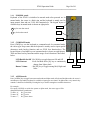
3.2.3.5
POWER or ON-OFF
The PT630 provides system power on/off feature.
1.)RESUME, 2.)AUTO OFF, 3.)ALARM
1.RESUME
Once 5 is selected, user can define the
When the Resume function is enabled, the PT630 will resume program execution
from the last turn-off point when it is powered on again. The default setting is ON
(enabled).
1.
2.
Press 1 (1.RESUME)
At the STATUS SETUP Menu, use the [] key to select between
RESUME ON (enable Recovery) and RESUME OFF (disable recovery)
3.
Press [ENT] to complete the setting
2.AUTO OFF Use the [] key to set auto-off timeout from 1 to 9 minutes. The PT630 will turn
itself off automatically after being idle for the time period specified in the AUTO
OFF setting. The default setting of AUTO OFF is 5 minutes. The auto-off feature is
disabled when set to 0 minutes.
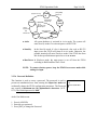
A smart power management system is built in PT630 hardware and software to
conserve battery power. The PT630 power transition flow is as follows:
PT630 Operation Guide
program running
press [PWR]
(switch on)
POWER
ON
press [PWR]
(switch off)
SHUT
DOWN
ACTIVE
wait on
keyin/scan
OR
call INT 22H
Page 24 of 41
key in
bar code scan
RS232 input
Auto-off timeout
NMI
POWER
FAILURE
STAND
BY
press [PWR] (switch off)
♦Active
All system hardware is activated in Active mode. The system will
enter Stand-by mode if it waits on input or call INT 22H.
♦Stand by
In the Stand-by mode, if a key is depressed, a bar code or RS-232
input occurs the PT630 will return to Active mode. Otherwise, the
portable terminal will enter Shutdown mode if the PT630 has been
idle for the specified timeout period as set in AUTO OFF.
♦Shut Down In Shutdown mode, the main power is cut off from the PT630
excluding its RAM and Real Time Clock.
NOTE: To conserve battery power, keep the PT630 in STAND BY mode while
waiting for input.
3.2.3.6 Password Definition
This function is used to create a password. The password is used to
prevent an unauthorized user from entering the Supervisor mode and
accidentally change the PT630 configuration parameters. The Password
may consist of maximum ten (10) alphanumeric characters ('A'-'Z',
'0'-'9'). The Default password is “600”.
At the User Mode menu:
1. Press 6 (6.PSWD)
2. Enter the new password
3. Press [ENT] to change the Password
OLD PASSWORD:
600
NEW PASSWORD:
█
PT630 Operation Guide
Page 25 of 41
3.2.3.7 Initialization
The user can command the PT630 to execute a Cold Start that will clear all data stored in the
RAM Disk and configure the terminal to default values.
Make sure your data has been backed up to a Host/PC before performing this
function.
At the Supervisor Mode menu:
SELECT 7
1.DEV
3.MEM
5.PWR
7.SYS
2.TERM
4.FORM
6.PSWD
8.DIAG
Select 1
<SYSETEM INITIAL>
1. COLD START
2. 2.PROGRAMMING
!! WARMING !!
PRUGE RAM DISK!
Are You Sure ?
1=YES/0=NO
Select 2
<PROGRAMMING>
1.ADD PROGRAM
2.delete all
3.update bios
When 1.COLD START is selected, press [1] for YES to confirm and execute a Cold Start, purge
the RAM DISK and return to the Ready Mode menu. Press [0] for NO, abort Cold Start and return
to User Mode Menu
When 2.PROGRAMMING is selected, there is three items can be choose. This is one of the main
feature provide by the PT630. User can select one of the program to add/erase user’s program
saved in the FlashROM of the PT630, or updating the PT630 system BIOS firmware.
1. ADD PROGRAM, the PT630 allows user store the application program into the FlashROM.
The size of the FlashROM for the application program is 128KB. When ADD PROGRAM
was selected, the PT630 will shows the available FlashROM free information on the screen.
User may save multiple application programs into the FlashROM if the free space is still
available. User may move the application program from the RAM disk to the FlashROM and
free up RAM disk for data storage. This feature will also prevent any application program lost
due to any accidental system failure or cold start.
2. DELETE PROGRAM, it allows user delete all of the application programs stored in the
FlashROM. User will not allow to delete any single application program but delete all the
application program store in the FlashROM. User will need to confirm the program delete
twice in case of any accidental input.
3. UPDATE BIOS, the PT630 allows the user to update or change system BIOS in the field.
Once the UPDATE BIOS been selected, the PT630 will search for any update BIOS file in the
RAM disk performing the update. If BIOS file is not found, the PT630 will wait for the file to
be downloaded from the communication port. After the upgrading is completed, the PT630
will automatically execute a COLD START. When this function has been chose, you will see
the following windows and do the selection;
PT630 Operation Guide
Erase all data
In RAM & FLASH !
Continue ?
(YES/NO)
Select YES
< PROGRAMMING >
Page 26 of 41
If BIOS file found
Select 1
Are you sure ?
1=YES/0=NO
< PROGRAMMING >
Change BIOS to
V.5.X
1=YES/0=NO
Select NO
<SYSTEM INITIAL>
1.COLD START
2.PROGRAMMING
Select 1
WARNING
: Before doing any system initialization, please make
sure that you have already backup or upload all data
files stored in the PT630 to your Host/PC.
3.2.3.8
Diagnostics
< PROGRAMMING >
Please download
BIOS file …
If BIOS file not found
1. The PT630 has a built-in diagnostics program to test the terminal's hardware. The test routines
are data destructive. Therefore, before running the diagnostic program, make sure you back up
the data in the PT630.
When a H/W or S/W service has been made on the PT630, such as maintenance,
repair or upgrade, it is strongly recommended to run the diagnostic program.
Diagnostic menu
At the Supervisor Mode menu:
0.All 1.RAM 2.KEY
3.232 4.LCD 5.RTC
6.SCANNER
7.RAM BCAKUP
8.EXIT
1. Press 8 (8.DIAG)
2. The LCD will display the diagnostic menu as shown on the left
3. Select 0-8 to run the desired diagnostic routine
SELECT (0-8)?_
0. All
Run all diagnostic routines from 1 to 8 shown below.
1. RAM
Fixed pattern stuck at fault check (00, FF, 55, AA).
Address test: write odd, even address data into corresponding
memory location, and verify it.
2. KEY
The LCD shows the legend of a key as it is pressed. Press [CMD],
then [1] to return to the diagnostic menu.
3. 232
Loop back the PT630 RS232 port by connecting TxD and RxD pins
together. All communication parameters are set to default values
except baud rate is set to 57600 bps. The status of the tests is shown
on the LCD.
Darken the dots of the LCD screen and cycle power to the LCD
backlight to check if the LCD functions OK.
4. LCD
5. RTC
Current time/date is displayed. Verify. Press any key to return to the
diagnostics menu.
PT630 Operation Guide
Page 27 of 41
6. SCANNER
Connect a bar code scanner to test bar code input by scanning bar
code labels. Press any key to return to the diagnostics menu.
7. RAM BACKUP
Follow the instruction displayed on the LCD to press the [PWR] key
to turn the power off and on to verify the memory backup.
8. EXIT
Return to the Ready mode of operation.
PT630 Operation Guide
Page 28 of 41
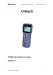
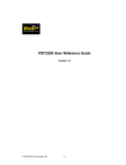
Chapter 4. HARDWARE OVERVIEW
4.1 INTRODUCTION
The PT630 is a handheld data terminal that has an integrated laser-scanning module or clip-on
pen module for bar code reading. A rechargeable Li-ion battery pack power the PT630. A lithium
backup battery preserves data stored in the RAM when the power main battery is used up or
during the replacement of the main battery.
PT630 Hardware Configuration
PT630 Operation Guide
Page 29 of 41
4.2 FEATURES
• 16-bit Microprocessor, 16Mhz Clock
• Real Time Clock Integrated Circuit (IC)
• 512 KB, 1.5MB, 2.5MB, 4.5MB CMOS (RAM) Memory.
• 26 alphanumeric rubber keys with 1 scanner trigger switch
• 128x64 pixel graphic backlit LCD with selection between 16-column by 4-line in 8x16 font and
20-column by 8-line in 6x8 font
• Power by Li-ion @ 3.6V 880mAH Rechargeable Battery-pack.
• 3V 190mAH Lithium Data Backup battery.
• Power Low Status Indicator for Main and backup batteries.
• 256KB Flash ROM, 128k for DOS-based system, the other 128K for user application program use.
4.3
I/O Ports
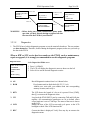
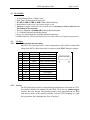
4.2.1 The PT630 has three interface ports:
An RS232 I/O serial port can be used to communicate with a host PC and normal
charge from RS232 cable when cable is connected with 9VDC/1A power adapter.
Pin
Signal
1
2
3
4
5
6
7
8
9
10
11
12
DCD
RXD
TXD
Direction
Description
Not support
Input
Output
Receive date
Transmit date
DTR
Output
Data Terminal Ready
GND
Reference
Ground
DSR
Input
Data Set Ready
RTS
CTS
Output
Input
Request to send
Clear to send
RI
Bat(+)
Bat(-)
Ext 9V
Not support
4.2.2 Scanner
The PT630 has provision for an integrated high performance scan engine or CCD,
and a built-in decoder for reading bar code labels. There are one scanner-trigger
switches above the keypad. The scanning window of the integrated unit sits flush
with the top surface of the portable terminal; with the PT630 standing in a right
side up position, the scanning beam, fires off upward.
PT630 Operation Guide
Page 30 of 41
4.3.3 PT630 CHARGING/COMMUNICATION CRADLE
An optional charging/communication cradle (dock station), model PT063, gives users a convenient
environment for daily use of the PT630. The cradle has provisions for a quick charge circuit to fully
charge the Li-ion battery pack installed in the unit in about 2~3 hours. The cradle also allows users
to link the PT630 to host computer either through RS-232 point-to-point (PT063-1), RS-485 multipoint (PT063-2) connection or modem (PT063-3) for data communication. For detail information
of cradle, please refer to user manual of PT063.
PT630 Operation Guide
Page 31 of 41
Chapter 5. COMMUNICATION
5.1 INSTALLATION
The RS-232 port of PT630 can communicate with the serial port of a host computer. There are
two ways to carry out communication sessions:
(1) LOCAL : Directly connect to the serial port of your computer system.
(2) REMOTE : Connected by two attached modems and one telephone line.
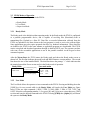
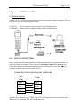
5.1.1 LOCAL CONNECTION:
In the Local connection method, the PT630 is directly connected by a null modem cable to the
serial port of the host computer. This is the way to download or upload files from/to your
PT630. Note that the communication parameters must be matched on your PT630 and host
computer, otherwise, the communication will fail.
CONNECTING THE PT630 TO A HOST COMPUTER
Host
Computer
9 Pins
2 RXD
3.TXD
5 GND
7.RTS
8 CTS
PT630
3 TXD
2 RXD
5 GND
8 CTS
7 RTS
When the flow control is set to CTS/RTS, the CTS (RTS) signal of one end is necessary to be
linked to the corresponded RTS (CTS) on the other end.
PT630 Operation Guide
Page 32 of 41
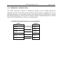
5.1.2 REMOTE CONNECTION:
The remote connection of PT630 is established by linking a pair of modems through the
telephone line. Once your PT630 has been connected with a modem to a telephone line, you can
dial from the PT630 to a remote host computer. The computer needs to be attached to a modem
through the telephone line. After the line is connected, the data communication process can start
between PT630 and PC/Host as if the two were linked locally.
CONNECTING THE PT630 TO A external MODEM :
PT630
Modem
2 RXD
3 TXD
2 RXD
3 TXD
4 DTR
5 GND
6 DSR
7 GND
6 DSR
7 RTS
20 DTR
5 CTS
8 CTS
4 RTS
PT630 Operation Guide
Page 33 of 41
5.2 DOWNLOADING AND UPLOADING
The PT630 supports the MULTI protocol and ESC commands for serial data communication.
Once the PT630 and PC are physically connected, a data communication processing will be
established when a program running on the PC sends the ESC command consistent with the
protocol specified in the PT630.
Connection
Point-to-point
Multi-point
Protocol supported
OFF, or MULTI
MULTI
Please refer to the PT630 Programming Reference Manual for detailed description of ESC
commands.
Before you download or upload a file from the PC to the PT630, connect your PT630 and HOST
using the LOCAL method.
PT630 Operation Guide
5.2.1
Page 34 of 41
Downloading a Jobgen Pro application from Host to PT630
This function downloads an existent JobGen Plus application from host to the PT630.
On PT630:
• Connect the RS-232 port of PT630 to the COM port of your PC by a null modem cable.
• Press [⊙] key to power up the PT630.
• Check the parameter settings of protocol and communication parameters of PT630. These
settings must match the settings as defined in the configuration of JobGen Plus application
program. If AutoSeek baud rate function is enable on JobGen Plus’s PTComm Manager, you
don’t need to care about PT630’s baud rate setting, but Protocol setting should be set as
Multi and other’s communication parameter should be “N,8,1”.
On HOST:
• Run JOBGEN Plus program.
• Open Job file which is targeted to be run on PT630.
• Press F4 key (or click Make Job icon, or select Built Make Job).
5.2.2
Uploading JobGen Plus from PT630 to HOST
Having collected the data into the PT630, the user can upload one or more collected data files to
a PC.
On PT630:
• Connect the RS-232 port of PT630 to the PC’s COM port PC with a null modem cable.
• Press [⊙] key to power up the PT630.
• Check the parameter settings of protocol and communication parameters of PT630. These
settings must match the settings as defined in the configuration of JobGen Plus application
program. If AutoSeek baud rate function is enable on JobGen Plus’s PTComm Manager, you
don’t need to care about PT630’s baud rate setting, but Protocol setting should be set as Multi
and other’s communication parameter should be “N,8,1”
On HOST:
• Run JOBGEN Plus program.
• Press F10 key (or click PTComm Manager icon, or select Tools PTComm Manager
• Double click Portable icon on right-upper windows and it will list down all of files which is
stored on PT630
• Click file which will be sent back to PC and drop it into left windows on right path.
PT630 Operation Guide
Page 35 of 41
5.2.3 Downloading a file from Host to PT630 using the Kermit Server
This function downloads a file from host to the PT630.
On PT630:
• Connect the RS-232 port of PT630 to the COM port of your PC by a null modem cable.
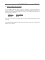
• Press [⊙] key to power up the PT630.
• Check the PT630 protocol and communication parameter settings.
• Press and hold down [CMD] key for 2 seconds to enter User mode, then select “3.COM” in
User mode to enter Kermit server mode.(see On HOST to process file download from Host
side).
Note : You can press [CMD] and [Alpha] to exit Kermit server and return to Ready mode
On HOST:
•
•
•
Run KERMIT.EXE program on PC. The program is in the PT630 Communication Utility
Diskette
First set the communication parameters to match the portable’s, then invoke download
command by entering “SEND filename”.
Enter [Q] to return to DOS.
PT630 Operation Guide
5.2.4
Page 36 of 41
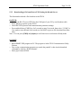
Uploading files from PT630 to HOST using the Kermit Server
Having collected the data into the PT630, the user can upload one or more collected data forms
to your PC.
On PT630:
• Connect the RS-232 port of PT630 to the COM port of your PC with a null modem cable.
• Press [⊙] key to power up the PT630.
• Check the PT630 protocol and communication parameter settings.
• Press and hold down [CMD] key for 2 seconds to enter User mode, then select “3.COM” in
User mode to enter Kermit server mode. (see On HOST to process file download from Host
side)
On HOST:
• Run KERMIT.EXE program on PC. The program is in the PT630 Communication Utility
Diskette.
• First, set communication parameters to match the portable’s. then invoke upload command
by entering “GET filename”.
• Enter [Q] to return to DOS.
PT630 Operation Guide
Page 37 of 41
Chapter 6. Troubleshooting
1. If power-low icon indicator of main battery shown on LCD screen,
Plug in the 9V adapter to charge the battery pack for 2~3 hours.
2. If can not power up PT630 after pressing [⊙] key,
•
Charge the battery pack for 2~3 hours.
3. If can not power up PT630 after charging battery pack for 2~3 hours.
•
•
Check if the battery pack is placed and connected properly in the battery compartment, or
Change the battery pack and charge it for 2~3 hours. If problem persists, call for service.
4. If PT630 does not upload data to host,
•
•
•
Check if the PT630 communication parameters (COM port, baud rate, data bits, parity,
stop bit ) matched the Host’s setting, or
Check if the cable is plugged tightly, or
Check if connectors (on cable) have correct pin assignment.
5. If host can not download application program to PT630,
•
•
•
Check if the host communication parameters (COM port, baud rate, data bits, parity, stop
bit ) matched the portable’s setting, or
Check if the cable is plugged tightly, or
Check if connectors (on cable) have correct pin assignment.
6. If scanner does not scan,
•
•
•
Check if the type of scanner port is set correctly, or
Check if symbology used is enabled, or
If it still fails, call for service.
7. If keypad does not work properly,
•
•
Verify operation steps with user's manual, or
Power off and on your PT630, then press some keys to check if an audible beep is
generated for each key pressed. If not, call for service.
PT630 Operation Guide
Page 38 of 41
8. If encounter any other abnormal symptoms,
Caution: The following process will clear all data in PT630 RAM disk memory)
Reset (cold start) the PT630, press [CMD], [] and [⊙]
simultaneously, press [3] in “Start Menu” press ENTER. See if symptoms went away. If not, call
for service.
PT630 Operation Guide
Page 39 of 41
Chapter 7. POWER SOURCES
A Li-ion battery provide main power source. A Lithium battery is used to back up the system
real time clock and content in the RAM memory when the main power source is not available.
NOTE. When using the PT630 for the first time, the main battery must be charged for 3 hours.
The PT630 checks the power level of the main battery when the portable terminal is in use;
however, the backup battery is only checked during power-on-test. Both low battery conditions
will be signal to the user by a warning message on the LCD.
When the main battery reaches a low condition, the LCD flashes a warning Message (“Main
Battery Low”) at one minute intervals while the portable terminal is on. The main battery can
continue to supply power in normal operation for approximately 10~30 minute However, the
level may reach the PT630 power cutoff point and automatically turn the Portable terminal off. In
this situation, the lithium battery continues to back up data and application programs in RAM
and the PT630 cannot be powered up until the main battery is recharged or replaced.
PT630 Operation Guide
Page 40 of 41
7.1 MAIN/BACKUP BATTERY REPLACEMENT AND INSTALLATION
Main Battery
1. Make sure the unit is turned off.
2. Turn over the unit. Slide tab from right to left (see illustrations in next page).
3. Slide the main battery pack from battery compartment.
4. Insert the new main battery packet:
1.
2.
Use screw driver
or coin to screw
it anti-clockwise
Then remove
battery cover
3. Take battery out of
battery compartment
Lithium Back up Battery
1. Refer to the procedure in previous paragraph, un-screw the backup battery cover and as
illustration above to remove the lithium battery.
2. Insert a new battery into the holder with correct orientation.
3. Put the battery cover back.
☛
Make sure to back up your data in PDT before making the replacement the lithium back
up battery.
1.
2.
Remove backup battery
cover.
Remove backup battery
from backup battery
compartment
PT630 Operation Guide
Page 41 of 41
7.2 MAIN POWER BATTERY CHARGING WITH AC/DC ADAPTOR (Regular/Normal
Charge)
When the PDT shows “Main battery low” message or icon , the battery pack in PT630 needs to be
recharged. Plug one end of an AC-9VDC/1A power adapter into the DC-jack of RS232 cable and
the other end into a wall outlet. The battery pack will be fully recharged after 2-3 hours.
The PT630 uses an internal Lithium battery to back up the RAM memory and system real time
clock when the main battery stops supplying the required power.
7.3 MAIN BATTERY CHARGING WITH CRADLE
Connect power adapter to PT063 and insert PDT into the chamber of PT063. The battery of PDT can be
fully charged in about 2~3 hours and the status of battery charging is indicated by the LED on the front
panel of PT063.(please refer to PT063 manual for detail information. )
PT630 Operation Guide
Page 42 of 41
7.4 MAIN BATTERY STORAGE & SAFETY PRECAUTIONS
Charging Considerations
It is important to consider the surrounding temperature whenever you are charging the Li-ion battery pack.
The process is most efficient at normal room temperature or slightly cooler. It is essential that you charge
batteries within the stated range of 32°F to 113°F (0°C to 45°C). Charging batteries outside of the specified
range could damage the batteries and shorten their life cycle.
Effects Of Overcharging Batteries
Overcharging may occur when a Li-ion rechargeable battery is charged in regular or quick charging rate
after it has been fully charged, but there is no risk of overcharging while charged in trickle charging rate.
If Li-ion batteries of PT630 are charged by a power adapter plugged directly to its DC jack for too long,
they can sustain a temporary reduction of capacity due to overcharging. A battery left to charge for several
weeks may appear to have minimal capacity. This type of failure can be remedied by temporarily depleting
the battery of its power and recharging it to rejuvenate it. This condition can be prevented by avoiding
overcharging for long periods of time or always using PT063 to charge the batteries of PDT. The PT063
starts the charging process in quick charging rate and switches to trickle charging rate when it detects the
battery is fully charged.
Storage and Safety Precautions
Batteries should be stored in an open circuit condition and placed where there is no risk of accidental
shorting or other damage. Although charged Li-ion batteries may be left unused for several months, their
capacity may be reduced due to back up and internal resistance. If this happens they will require recharging
prior to use. Li-ion batteries may be stored at temperatures between -4°F and 158°F (-20°C to 70°C),
however they may be depleted more rapidly at the high end of this range.