1
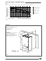
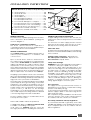
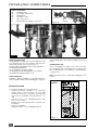
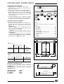
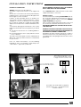
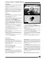
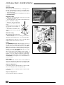
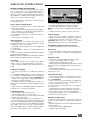
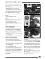
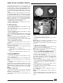
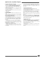
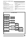
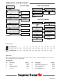
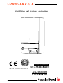
COMBITEK F 23 E
Installation and Servicing Instructions
IN WARRANTY
TECHNICAL HELPLINE
01773 828400
THIS IS A CAT II2H3+ APPLIANCE
01773 828100
1
INSTALLATION AND SERVICING INSTRUCTIONS
COMBITEK F 23 E
Note: The boiler serial number is marked on the data label attached to the PCB housing behind the front
lower section. Refer to the ‘Introduction’ section for a description of the basic functions of the boiler. The
‘User’ section describes how to safely operate the boiler.
Users’ Instructions
Introduction ..................................................... Page 2
Controls and lighting ................................................. 3
Draining and filling ..................................................... 3
Heating safety valve ................................................. 3
Servicing/maintenance ............................................ 3
Cleaning ..................................................................... 4
Boiler casing ............................................................... 4
Installation Instructions
Introduction ..................................................... Page 4
Changing gas type ................................................... 4
Technical data ...................................................... 4 - 5
Dimensions .................................................................. 5
Boiler schematic ........................................................ 6
Terminal positions ....................................................... 7
Heating and hot water system design .................... 7
Boiler installation ........................................................ 8
Horizontal flue installation ......................................... 9
Vertical flue installation ........................................... 10
Electrical connection .............................................. 11
Commissioning ......................................................... 12
Adjustments .............................................................. 13
Safety device ........................................................... 13
Setting ....................................................................... 14
Servicing Instructions
Routine cleaning and inspection ............... Page 15
Replacement of parts ...................................... 16 - 21
Schematic wiring diagram ..................................... 22
Fault finding ....................................................... 23 - 24
Spare sparts .............................................................. 24
Mandatory warning for CE countries
WARNING, these appliances were designed, approved and inspected to meet the requirements of the
English market. The identification plate located on the inside of the appliance certifies the origin where the
product was manufactured and the country for which it is intended.
If you see any exception to this rule, please contact your nearest stockist.
Thank you in advance for your assistance.
UK
USER INSTRUCTIONS
INTRODUCTION
The Combitek F 23 E is a wall mounted combination
boiler providing central heating and instantaneous
domestic hot water.
These instructions should be carefully followed for
the safe and economical use of your boiler.
Gas leak or fault
If a gas leak or fault exists or is suspected, turn the
boiler and gas supply off and consult the local gas
company or your Installer/Service provider.
In case of power supply failure
The boiler no longer operates.
As soon as power supply is restored, the boiler will
restart automatically.
In case of loss of water in the system
CAUTION. The boiler is installed as part of a sealed
system which must only be drained and filled by a
competent person.
2
If the pressure shown on the pressure gauge is less
than 1.5 bar the system must be filled up.
Important notice: A central heating system cannot
operate satisfactorily unless it is properly filled with
water and unless the air initially contained in the
piping systems has been properly bled off. If these
conditions are not satisfied, air noise will occur within
the system and the boiler may fail to operate.
Air in the heating system
Persistent air in the heating system may indicate
leaks in the system or corrosion taking place. Call
your Installer/Service provider.
Overheating safety
In the event of problem, the overheat safety device
causes safety shutdown of the boiler. If this happens,
call your Installer/Service provider.
USER INSTRUCTIONS
2
The control panel is located on the front
bottom section. The controls on this panel
allow the boiler to be started, shut down
and controlled during use.
1
24
3
23
22
4
12
5
21
6
20
I
19
7
9
8
18
3
9
17
16
0
6
10
15
14
13
12
11
1
1 - Pressure / Temperature gauge
2 - Hot water / Heating temperature
control & summer / winter switch
3 - Timeclock
4 - Mains On/Off switch
2
1
4
2
3
4
5
Diagram 1
CONTROLS AND LIGHTING
Make sure that:
The boiler is connected to the electrical supply.
The boiler gas service cock is open.
The pressure gauge reads between 1.5 and 2 bar.
The boiler is now ready to start.
2
1
24
3
23
22
4
12
5
21
6
7
8
18
9
10
15
14
13
12
11
1
0
6
16
Setting to ‘Winter’ mode
(Heating and hot water)
Place switch (2) to the
Winter position
9
17
Setting to ‘Summer’
mode (Hot water only)
Place switch (2) in the
Summer position (see
diagram 2).
I
19
To stop the boiler
Place switch (4) to the Off position (0).
20
To start the boiler
Switch on using mains switch (4), see diagram 1.
Place switch (2) in the Summer or Winter position
2
3
Diagram 3
4
5
Diagram 2
Adjust the heating temperature control (2) to the
desired temperature.
The heating will operate according to the
requirements of the timeclock and/or room thermostat if fitted or, will operate according to the
system requirements.
Domestic hot water always has priority over central heating.
Timeclock
To set the clock rotate actuater mechanism
clockwise, by hand, until current time is indicated.
See diagram 3.
Note: The time is set in 24 hour format, for example
1300pm for 1pm
Setting the programme ‘ on & off ’ times
Select the on times by pushing the black tappets to
the outside
Select the off times by pushing the black tappets to
the inside
The clock shown in diagram 3 is set as follows
On
07.00am to 09.00am
Off
09.00am to 4.00pm
On
4.00pm to 10.00pm
Off
10.00pm to 07.00am
To override or advance the clock
The clock has a manual on/off switch see diagram
3 which opperates as follows:
Upper position 1
Heating on continuosley
Middle position
Heating on timed
Lower position 0
Heating off
DRAINING AND FILLING
Caution: The boiler is installed as part of a sealed
system which must only be drained and filled by a
competent person.
Note: If there is persistent loss of system pressure, you
must consult your Installer/Service Provider.
HEATING SAFETY VALVE
CAUTION: A safety valve with a discharge pipe is
fitted to this boiler.
The valve MUST NOT BE TOUCHED except by a
competent person. If the valve discharges at any
time, switch the boiler off and isolate it from the
electrical supply. Contact your Installer/Service
Provider.
SERVICING/MAINTENANCE
To ensure the continued efficient and safe operation
of the boiler, it is recommended that it is checked
and serviced at regular intervals. The frequency of
servicing will depend upon the installation conditions and usage but, in general, once a year should
be enough.
3
USER INSTRUCTIONS
CLEANING
The boiler casing can be cleaned with a damp cloth
followed by a dry cloth to polish.
Do not use abrasive or solvent cleaners.
BOILER CASING
CAUTION: Do not remove or adjust the casing in any
way, as incorrect fitting may result in faulty operation.
If in doubt, contact your Installer/Service Provider.
INSTALLATION INSTRUCTIONS
Accessories
A range of accessories are available including,
vertical flue components. For further information,
contact you nearest stockist.
INTRODUCTION
The Combitek F 23 E is a wall mounted combination
boiler providing central heating and instantaneous
domestic hot water.
Note: this boiler requires no fixing jig and has top
outlet flueing only ( there is no rear flue option ).
Gas Safety (Installation and Use) Regulations
In the interests of gas safety, it is the law that ALL gas
appliances are installed and serviced in by a
competent person in accordance with the above
regulations.
The boiler is of the II2H3+ category for use with
Natural gas (G20). To convert to Butane (G30) or
propane (G31), the following kit is required.
Gas conversion kit :part number 86161
Gas leak or fault
If a gas leak or fault exists or is suspected, turn off the
boiler and gas supply and consult the local gas
company or your Installer/Service Provider.
The boiler has a fan assisted, balanced, flue which
both discharges the product of combustion to, and
draws the combustion air from, the outside of the
building.
TECHNICAL DATA
Heating output
automatically variable from
8,9 kW to 23,3 kW
30,000 BTU/H to 80,000 BTU/H
Efficiency
82,4 %
Heating adjustment
38°C to 90°C
Expansion vessel effective capacity
6,5 l
Expansion vessel charge pressure
0,5 bar
Maximum system capacity at 75°C
140 l
Safety valve, maximum service pressure
3 bar
Products outlet diameter
60 mm
Fresh air inlet diameter
100 mm
Burner injector
Inlet pressure
Gas rate (maximum)
Gas rate (minimum)
Hot water output
automatically variable from
8,9 kW to 23,3 kW
30,000 BTU/H to 80,000 BTU/H
Maximum hot water temperature
65 °C
Specific flow rate (for 35°C temp rise)
9,6 l/min
Threshold flow rate
3 l/min
Nominal water flow rate
12 l/min
Maximum supply pressure
10 bar
Minimum operating pressure
0,5 bar
Electrical supply
Maximum absorbed power
230 V
130 W
Natural Gas
(G20)
Butane
(G30)
Propane
(G31)
Town gas
(G130)
1,2 mm
20 mbar
2,70 m3/h
1,13 m3/h
0,73 mm
29 mbar
2,01 kg/h
0,84 kg/h
0,73 mm
37 mbar
1,98 kg/h
0,74 kg/h
2,4 mm
8 mbar
3,88 m3/h
1,63 m3/h
(kW)
(Btu/h)
Heat output
8,9
10
11
12
13
14
15
16
17
18
19
20
21
22
23,3
30387 34142 37557 40971 44385 47799 51214 54628 58042 61456 64871 68285 71699 75113 79552
(kW)
(Btu/h)
Heat input
11,9 13,2 14,4 15,7 16,9 18,1 19,2 20,4 21,5 22,7 23,8 24,9 26,0 26,9 28,3
40678 45130 49332 53481 57579 61627 65626 69575 73477 77333 81142 84906 88913 91713 96602
GAS
G 20
(mbar) 1,3
2,1
2,6
3,0
3,5
4,0
4,5
5,1
5,7
6,3
6,9
7,6
8,3
8,8
9,8
G 30
(mbar) 3,7
5,3
6,3
7,4
8,6
9,8
11,1
12,5
13,9
15,4
17,0
18,6
20,4
21,7
24,1
G 31
(mbar) 4,0
6,3
7,5
8,8
10,2
11,7
13,3
14,9
16,7
18,5
20,3
22,2
24,4
26,0
28,8
4
INSTALLATION INSTRUCTIONS
Pump:
Available pressure (kPa) between
heating flow and return
The performance of the pump varies according to the pump bypass setting, see diagram 3.
50
1
40
2
3
30
4
20
5
Bypass fully shut
3
4
5
Open 1/2 turn
Open 1/4 turn
Open 1 turn
Open 2 turns
Pom 052
10
1
2
500
0
(10 kPa = 1 m WG)
1000
Flow rate through heating system (I/h)
Diagram 3
DIMENSIONS
The boiler is delivered in two
separate packages:
- The boiler
- The flue system
Hab 271a
623
802
857
23
4
Clearances
The boiler can be installed with
the following clearances:
50 mm either side of the boiler
600 mm to the front of the boiler
300 mm below the boiler
Net weight:
41 kg
Gross weight: 43 kg
410
8
37
Diagram 4
5
INSTALLATION INSTRUCTIONS
BOILER SCHEMATIC
3
4
6
7
8
9
10
11
12
13
14
16
17
-
Ignition module
Heating temperature adjuster
Pressure gauge
non-return valve
Expansion vessel
Pump
Automatic air vent
Burner
Burner pressure test point
Heat exchanger
Gas valve
Heating and hot water thermistor
Ignition electrode
19
20
21
22
23
24
-
Overheat thermostat
Flame sense electrode
Loss of water pressure switch
Fan
Air pressure switch
Gas cock
A
B
C
D
E
-
Heating return
Cold water inlet
Heating flow
Domestic hot water flow
Gas supply
23
22
13
19
20
17
12
16
11
10
14
9
3
8
7
6
4
21
24
Diagram 5
6
B
C
D
E
Shy 131b
A
INSTALLATION INSTRUCTIONS
Minimum dimensions (in mm) for the positioning of flue terminals
-
Under a window ..............................................
Under an air vent ............................................
Under a gutter .................................................
Under a balcony .............................................
From an adjacent window ............................
From an adjacent air vent .............................
From vertical drain pipes or soil pipes ..........
From an external corner of the building ......
From an internal corner of the building .......
From the ground or from another floor ........
Between two terminals vertically ..................
Between two terminals horizontally ..............
300
300
75
300
300
300
75
300
300
300
1500
300
G
N
C
E
F
M
A
B
D
I
H
L
Ven 060b
A
B
C
D
E
F
G
H
I
L
M
N
Diagram 6
TERMINAL POSITIONS
The minimum acceptable spacings from the terminal to obstructions and ventilation openings are
shown in diagram 6 :
Cupboard or compartment ventilation
The boiler can be fitted in a cupboard or
compartment without the need for additional permanent high and low level ventilation
HEATING SYSTEM DESIGN
The combitek F 23 E is compatible with any type of
sealed system installation, i.e. radiators, fan
convectors etc.
Pipe sectional areas shall be determined in
accordance with normal practices, using the pump
curve, refer to ‘Technical Data’. The distribution system
shall be calculated in accordance with the output
requirements of the actual system, not the maximum output of the boiler. However, provision shall be
made to ensure sufficient flow so that the temperature
difference between the flow and return pipes is less
than or equal to 20oC. The minimum flow is 500 l/h.
The piping system shall be routed so as to avoid any
air pockets and facilitate permanent venting of the
installation. Bleed fittings shall be provided at every
high point of the system and on all radiators.
The total volume of water permitted for the heating
system depends, amongst other things, on the static
head in the cold condition. The expansion vessel on
the boiler is pressurised at 0,5 bar (corresponding to
a static head of 5m wg.) and allows a maximum
system volume of 140 litres for an average
temperature of 75oC and a maximum service pressure of 3 bar. This pressure setting can be modified at
commissioning stage if the static head differs.
Provision shall be made for a drain valve at the
lowest point of the system.
Thermostatic radiator valves are permitted.
A suitable WRC approved filling loop must be fitted
to enable correct filling of the system.
In all cases, it is ESSENTIAL that the system be
thoroughly flushed prior to installing the new boiler.
DOMESTIC HOT WATER SYSTEM DESIGN
Copper tubing must be used for the domestic hot
water system. Unnecessary pressure losses should be
avoided.
The domestic hot water supply pressure must be
between 0.5 and 10 bar. If the pressure exceeds 3
bar, a pressure reducing valve must be fitted.
Hard water areas
In areas where the water hardness exceeds 200 mg/
litre, it is recommended that a suitable scale reducing
device is fitted.
Heating system connections - Pipe Ø 22 mm.
Hot water system connections - Pipe Ø 15 mm.
Gas connection - Pipe Ø 22mm.
Safety valve discharge
WARNING: It must not discharge above an entrance
or window or any type of public access area.
Connect the safety valve discharge pipe to the
valve, the discharge must be extended using not
less than 15 mm o.d. pipe, to discharge in a visible
position outside the building, facing downward,
preferably over a drain. The pipe must have a
continuous fall and be routed to a position so that
any discharge of water, possibly boiling or steam,
cannot create any danger to persons, damage to
property or external electrical components and
wiring. Tighten all pipe connection joints.
Gas connection
The supply from the governed meter must be of
adequate size to provide a constant inlet working
pressure of 20 mbar (8 in wg).
To avoid low pressure problems, it is recommended
that the supply is taken to the boiler using 22 mm
pipe as far as possible.
On completion, the gas installation must be tested
using the pressure drop method and purged in
accordance with the current issue of BS6891.
Gas Safety (Installation and Use) Regulations.
In your interests and that of gas safety, it is the law
that ALL gas appliances are installed and serviced
by a competent person in accordance with the
above regulations.
7
INSTALLATION INSTRUCTIONS
Filter
Fibre
washer
B
Diagram 7b
Pla 277
Isolating cock
Flow restrictor
Boiler connections
A
Heating return
B
Cold water mains inlet
C
Heating flow
D
Hot water outlet
E
Gas connection
F
Safety valve discharge connection
Pla 275
F
A
B
D
C
E
Diagram 7a
Installing the boiler
Prior to installing the boiler, the system must be
thoroughly flushed to eliminate any foreign bodies
and contaminents such as filings, solder, particles,
oil, grease etc.
120 mm
8
37
Ø8
Ø8
691 mm
Ø8
65 mm
410
BOILER INSTALLATION
To install the boiler, proceed as follows:
· Allowing sufficient clearances for servicing/
repair, place the template on the wall
Determine the position of the flue hole and drill
hole for flue, preferably using a 120 mm core
drill.
· Drill two holes for the hanging bracket, Plug
and screw to wall.
· Fasten lower spacing brackets to boiler (see
template)
· Remove template.
· Hang the boiler on the hanging bracket.
110665 B
Ø 105
857
Boiler
Template
4
Note: Solvent products could cause damage to the
system.
23
Sheet metal parts
WARNING: When installing or servicing this boiler,
care should be taken when handling the edges of
sheet metal parts to avoid the possibility of personal
injury.
802
Statutory requirements
The installation of this boiler must be carried out by
a competent person in accordance with the relevant requirements of the current issue of:
The Gas Safety (Installation and Use) Regulations
The Building Regulations
The local water company Bylaws
The Building Standards Regulations (Scotland)
The Health and Safety at Work Act
Spacing plate must be attached to
boiler prior to hanging
WALL SIDE
55
Diagram 8
8
55
57,5
57,5
Ins 071a
BOILER SIDE
INSTALLATION INSTRUCTIONS
HORIZONTAL FLUE INSTALLATION
• Fit gasket (H) onto underside of elbow (C)
• Carefully insert ‘o’ rings (J) into upper and lower
parts of inner elbow
• Fit elbow onto boiler using screws provided (I)
• Offer flue pipes to elbow, note that pipe (B) should
be inside pipe (A) before connection. Push pipe
(B) into inner elbow socket and connect pipe (A)
with collar (D). Locking clips (E) are used to lock
collar into position.
• Parts (F) and (G) are used to seal brickwork gaps
if required. If using part (G) to seal inner wall, this
should be placed over flue before installation.
B
D
C
E
G
F
J
I
H
Pho 422
Calculation of flue cutting lengths
· Measure wall thickness e (mm)
· For side flues, measure distance from inside face of
the side wall to the centre line of the boiler and
subtract 205 mm to get dimension a (mm) see
diagram 10.
·
Refere to table 1 for the cutting lenghs of both
the inner and outer flue pipes for each of the
various flue options available.
·
Important: All flue cutting lengths must be
measured from the terminal end of the flue pipes,
see diagram 11.
·
When the dimension x measured on site is greater
than that given in table 1 a flue extension kit will be
required, refere to table 2 for details.
A
Diagram 9
The flue kit 86285 is 1000 mm long and comprises:
- Outer pipe .................................................... A
- Inner pipe ....................................................... B
- Flue elbow ..................................................... C
- Fixing collar ................................................... D
- Locking clips .................................................. E
- External rubber sealing collar ..................... F
- Internal flange .............................................. G
- Gasket ........................................................... H
- Screws .............................................................. I
- 'O' rings ........................................................... J
Table 1
Flue cutting lengths
Cutting length (mm)
inner pipe
Comments
e + 144
e + 224
maximum
wall thickness "e"
without
extension
511 mm
e
Table 2
Number of extension kits required
Dimension 'X'
No. of
extension kits
Side flue
(left or right)
745 to 1745 mm
1527 to 2745 mm
1
2
e
X
X
Flue option
Diagram 10
Outer pipe
Maximum horizontal flue run 3m
For each 90o flue bend fitted, reduce overall flue
length by 1 m.
For each 45o flue bend fitted, reduce overall flue
length by 0.5 m.
Horizontal flue kit
Flue extension kit
90o bend kit
45o bend kit
a
a
Hab 210
outer pipe
Cutting length
86285
85091
85092
85093
Inner pipe
Cutting length
Ven 089
Flue option
Top outlet
rear flue
Diagram 11
9
INSTALLATION INSTRUCTIONS
VERTICAL FLUE INSTALLATION
A .................................................................... Gasket
B ..................................................... Vertical adaptor
C .................................................................... ‘O’ ring
D ....................................................................... Collar
E ...................................................................... Clamp
F ...................................................................... Screws
G .................................................................. Terminal
H ...................................................................... Screws
Fit gasket (C) onto underside of vertical adaptor
(B)..
· Carefully insert ‘O’ ring (A) into vertical adaptor
inner spigot.
· Fit adaptor correctly onto fan outlet.
· For flat roof installation, fit flat roof flashing collar
(part no. 85107)
· Fit flue terminal (L) onto roof ensuring flashing
makes a watertight joint.
· For pitch roof installation, fit pitch roof flashing
collar (part no. 85105)
· Fit flue terminal (G) onto roof ensuring flashing
makes a watertight joint.
NOTE: Maximum vertical height with no bends is 4 m.
A
Diagram 12
Show vertical kit adaptor & terminal
B
E
F
H
·
C
D
Note: Should it be necessary to cut the flue, always
cut equal amounts from both inner and outer pipes.
Maximum vertical flue run 11.5m
For each 90o flue bend fitted, reduce overall flue
height by 1 m.
For each 45o flue bend fitted, reduce overall flue
height by 0.5 m.
Vertical flue terminal (Black)
85103
Pitched roof flashing
Flat roof flashing
Flue extension pipe
90o bend kit
45o bend kit
85105
85107
85099
85101
85102
G
Diagram 12
10
INSTALLATION INSTRUCTIONS
DO NOT INTERRUPT THE MAINS SUPPLY TO THE BOILER
WITH A TIME SWITCH OR PROGRAMMER.
ELECTRICAL CONNECTION
Warning: This boiler must be earthed.
All system components must be of an approved
type.
Connection of the whole electrical system and any
heating system controls to the electrical supply must
be through a common isolator.
Isolation should preferably be by a double pole
switched fuse spur box having a minimum contact
separation of 3 mm on each pole. The fused spur
box should be readily accessible and preferably
adjacent to the boiler. It should be identified as to its
use.
A fused three pin plug and shuttered socket outlet
may be used instead of the fused spur box, provided
that:
a) They are not used in a room containing a bath or
shower.
b) Both the plug and socket comply with the current
issue of BS1363.
The mains electrical supply must be maintained at
all times in order to provide domestic hot water and
frost protection
The combitek F 23 E is delivered with 1metre mains
supply lead ready connected.
External controls
The boiler will work for heating AS DELIVERED without
a room thermostat fitted provided the two wires on
the integral external controls connection REMAIN
LINKED TOGETHER (as supplied).
If a room thermostat is required, it must be connected
as shown below and the link must be removed.
ANY ROOM THERMOSTAT USED MUST BE OF THE VOLTAGE FREE TYPE.
WARNING: ON NO ACCOUNT MUST ANY ELECTRICAL
VOLTAGE BE APPLIED TO EITHER OF THE TERMINALS OF
THE EXTERNAL CONTROLS CONNECTION
WARNING: This boiler must be wired in accordance
with these instructions. Any fault arising from incorrect wiring cannot be put right under the terms of the
guarantee.
Note: For further information, see The Building
Regulations 1991 - Conservation of fuel and power
- 1995 edition - Appendix G, table 4b.
When fitting an external control,
remove wire link (E) and connect
voltage free thermostat as shown
E
°C
sch 229
sch 228
For no external controls
leave wire link (E) in place
Diagram 13
sch 227
The mains electrical cable is supplied
with the boiler. It is coiled and tucked
inside the boiler
11
INSTALLATION INSTRUCTIONS
COMMISSIONING
The commissioning and first firing of the boiler must
only be done by a competent person.
Diagram 14
Filling the system
2
Open isolating coks to boiler
(see diagram 7a)
3
Sec 058
Open the tap on the system filling loop and fill the
system until the pressure
indicated on the display
is between 1 and 2 bar.
Reg 008
Undo, but do not
remove, cap on
automatic air
vent on top of
pump. Do not retighten cap.
5
Open various
hot water taps to
bleed system.
Ins 061
Bleed each radia
tor until a continuous jet of water is obtained.
Important:
- If this procedure is not carried out properly, the boiler
will go into safety lock-out until all of the air has been
purged.
- When venting air from boiler, do not touch the
schrader valve on the expansion vessel, it is NOT a
vent.
- Before starting the boiler, turn the pump impellor to
make sure it is free to move.
• Unscrew black cap on front of pump.
• Using screwdriver, push in pump spindle and turn
pump impellor 3 to 4 times. DO NOT HIT SPINDLE. Replace black cap.
Starting the boiler
Before starting the boiler check that:
- The gas meter tap is open. If using Butane or Propane, check that valve on storage cylinder or tank is
open.
- You have removed the two fan transit clips from fan.
12
Ins 062
4
6
Make sure that
pressure gauge
reads between 1 and
2 bar. Re-pressurise
system as necessary.
Sec 058
1
mec 117
Gas installation
It is recommended that any air is purged from the
supply at the gas inlet test point on the left hand
side of the gas valve, see diagram 14.
- The boiler gas service cock is open.
- The boiler is connected to the electrical supply and
switched on.
- The front casing is fitted.
First starting up
• Following the instructions given in the 'User Instructions' set boiler to run in central heating mode.
• Set boiler thermostat for maximum temperature
ensure timeclock is "ON" and check that any external controls, if fitted, are calling for heat.
• Allow the temperature to rise to the maximum
value, with all radiator valves open.
The temperature rise will cause release of the gases
contained in the water of central heating system.
- Gases driven towards the boiler will be automatically released through the automatic air vents.
- Gases trapped at the highest point of the system
must be released by bleeding the radiators.
Gas pressures
The main burner pressure should be checked during commissioning to make sure the correct output is obtained. Proceed as follows:
• Shut down boiler.
• Undo screw on burner pressure test point below
sealed combustion chamber and connect a
suitable manometer, see diagram 15.
• Start boiler as described in 'User Instructions'.
• Set boiler thermostat to maximum and check
that any external controls are calling for heat.
• Check that the reading on the gauge matches
that given in 'Technical Data' for the type of gas
being used.
• Adjust the range rating adjuster screw as necessary to obtain the desired input, see diagram 16.
• Shut down boiler.
• Remove manometer, tighten up test point screws
and check for gas soundness.
• Using a ball point pen, clearly indicate on the
data label the input the boiler is set to.
Note: This adjustment does not affect the domestic hot water output.
If measured burner pressure differs greatly from the
given figure, check the gas inlet pressure as follows:
• Shut down boiler.
• Remove screw from inlet test point on the side of
the gas valve, see diagram 14.
Diagram 15
Diagram 16
Reg 056
ADJUSTMENTS
On reaching maximum temperature, the boiler
should be turned off and the system drained as
rapidly as possible whilst still hot.
• Refill system to a pressure of 1.5 bar and vent as
before.
• Restart boiler and operate until a maximum temperature is reached. Shut down boiler and vent
heating system. If necessary, top up heating system and make sure that a pressure of 1.5 bar
is indicated on the pressure gauge when system is
COLD.
Des 044
INSTALLATION INSTRUCTIONS
• Connect a suitable pressure gauge.
• Start boiler as described in 'User Instructions'.
• Check that the inlet pressure reading matches
that given in 'Technical Data' for the type of gas
being used.
• Shut down boiler.
• Remove pressure gauge, tighten up test point
screws and check for gas soundness.
• If the gas pressure is incorrect, refer to the Fault
Finding section in 'Servicing Instructions'.
• If the inlet pressure is below that given, the gas
supply pipework/meter must be checked and any
fault corrected.
• In the case of an LPG installation, check the storage tank or cylinder, regulator and pipework.
SAFETY DEVICES
Air flow rate safety device
If an obstruction, even partial, of the flue occurs,
for any reason whatsoever, the built in safety system of the boiler will turn the boiler OFF and the
fan will continue to run.
The boiler will be ready to operate when the fault
has been cleared.
In case of power supply failure
The boiler no longer operates.
As soon as power supply is restored, the boiler will
be automatically restarted.
Overheat safety
In the event of a problem, the overheat thermostat causes safety shutdown of the boiler. Should this
occur, reset the thermostat by pressing the red
button. The overheat thermostat is located on the
RHS of the heat exchanger.
Important notice: A central heating system cannot
operate satisfactorily unless it is properly filled with
water and unless the air initially contained in the
piping systems has been properly bled off. If these
conditions are not satisfied, air noise will occur
within the system.
The COMBITEK F 23 E boiler has a built in frost protection device that protects the boiler from freezing. If the boiler is to be left and there is a risk of
frost, ensure that the gas and electrical supplies are
left connected and the summer/winter switch is in
the
position. The frost protection device will light
the boiler when the temperature of the boiler water falls below 6°C. When the temperature reaches
16°C, the boiler stops.
Note: This device works irrespective of any room
thermostat setting and only protects the boiler.
13
INSTALLATION INSTRUCTIONS
SETTINGS
Gas valve setting
All boilers are tested and factory set during manufacture. Should it be necessary to reset a gas valve,
for example after replacement, proceed as follows:
• Shut down boiler.
• Connect a suitable pressure gauge as described
in 'Commissioning'.
Diagram 17
Reg 013
Diagram 18
Reg 057
Mec 121
Maximum setting
• Remove one electrical connector from the
modulating gas valve coil.
• Turn the domestic hot water temperature adjuster to maximum setting.
• Remove the protective
cover from the gas valve adjuster.
B
Using a 2 mm Ø rod, press in
A
the spindle in the middle of
screw.
• Turn nut 'B' to obtain the desired pressure, see technical
data.
A
Minimum setting
This must be done AFTER the
maximum setting.
• Hold nut B to prevent from turning, turn nut 'A' to
obtain the desired pressure, see technical data.
After adjustment, refit the cover to the gas valve
adjuster and refit electrical connector.
Bypass
The COMBITEK F 23 E has a built-in bypass. This must
be adjusted according to the requirements of the
system, refer to the flow rate pressure curve (diagram 3). The boiler is supplied with the built-in bypass open a half a turn. It is adjusted by turning the
bypass screw (A), see diagram 17. Turn the screw
clockwise to close the bypass.
When using thermostatic radiator valves (TRV's), it
is recommended that an additional, adjustable
bypass of 15 mm minimum diameter is fitted between the flow and return of the heating circuit,
see diagram 6. Any bypass must be fitted before
system controls.
PCB Settings
The combitek has a switch SW1 on the main PCB
which incorporates two dip switches. Both these dip
switches should normaly be set to the Off position.
Purpose of dip switch 1 :
In the Off position the pump will be on and off with
the room stat (this is the normal position).
In the On position, the pump will be on and off with
the burner.
Purpose of dip switch 2 :
Not used in UK. Leave in off position.
14
ROUTINE CLEANING ANS INSPECTION
To ensure the continued efficient and safe operation of the boiler it is recommended that it is
checked and serviced at regular intervals. The frequency of servicing will depend upon the particular installation conditions and usage, but in general once a year should be enough.
It is the law that any servicing is carried out by a
competent person.
Service Check and Preparation.
• Operate boiler and check for any faults that
need to be put right.
• Isolate boiler from the gas and electrical supplies.
• On completion check all gas carrying parts for
soundness with leak detection fluid.
• The maximum domestic hot water flow rate is 12
litres/minute.
• Remove boiler casing as follows:
Upper front panel
• Disengage the two 'quarter turn' fasteners by
turning the heads of the screws a quarter of a turn
towards the centre of the boiler.
• Carefully lower the panel down on its hinge until
it is horizontal.
• Turn both plastic catches to release upper front
panel.
• Remove upper front panel by pulling forward at
the bottom and lifting off.
Note: The upper front panel is retained by a plastic
safety strap, disengage this before removal.
Side panels
• From below boiler, unscrew and remove black
plastic screws securing side panels to the boiler.
• Prise out black plastic inserts and lift panel off
boiler.
Combustion chamber
• Loosen two wing nuts on combustion chamber
cover.
• Disengage retaining lugs from holes in either side
of combustion chamber and move rods away to
clear combustion chamber sides, see diagram 19.
• Unclip two toggle clips holding upper part of
combustion chamber in place.
• Holding both sides, pull chamber forward to release it from underside of heat exchanger and out
of boiler.
• Take care not to damage insulation material on
inside faces of combustion chamber.
Cleaning the burner
• Pull off leads to ignition electrode.
• Pull off lead to flame sense electrode.
• Unscrew and remove screw holding earth lead
to flame sense electrode.
• Undo main gas supply nut from main burner.
• Unscrew and remove locking nut from both main
gas connection and burner pressure tapping point.
• Lift front edge of burner until tapping point and
gas supply connection are free. Remove burner
from boiler taking care to retain both fibre washers
and seal on gas supply for use on reassembly.
Diagram 19
Des 047
SERVICING INSTRUCTIONS
• Unscrew and remove two injector bar retaining
screws and separate injector bar from burner.
• Examine and clean injectors as necessary.
Note: Do not use a wire or sharp instrument on the
holes.
• Replace burner in reverse order to removal.
Heat exchanger
• After removal of burner, examine heat exchanger for any blockages or build up of deposits.
• Clean using soft brush or vacuum cleaner.
Important: Take care not to scratch or otherwise
damage painted surface of heat exchanger.
Reassembly of parts removed for servicing
• Replace all parts in reverse order to removal.
Flue system
• Check externally to make sure flue is not blocked.
• Inspect flue system to make sure all fittings are
secure.
Operation of fan
• Switch on electrical supply and turn on gas.
• Switch boiler On/Off switch to 1 (On).
• Light burner by opening a hot tap.
• Without upper front panel in place, burner should
be prevented from lighting by air flow detection
system.
• Refit upper front panel.
• Check that fan runs when burner is lit and stops
when it goes out.
Cold water inlet filter
• Drain down hot water circuit of boiler as follows:
• Close isolating valve on cold water inlet connection, see diagram 5.
• Open one or more hot water taps to drain boiler.
• Undo connecting nut from cold water inlet connection to gain access to filter.
• Remove restrictor, then filter from cold water inlet connection.
• Clean and inspect filter, replace if necessary.
• With both flow restrictor and filter in place, reconnect pipe to inlet connection and tighten.
• Fully open isolating cock on cold water inlet connection and check for leaks.
Operation of water valve
• With the Summer/Winter control in the 'Summer'
position, slowly open a convenient tap until boiler
lights.
• Measure water flow, it should not be greater than
3,5 litres/minute.
• If necessary, replace diaphragm.
• Replace all outer panels.
15
SERVICING INSTRUCTIONS
To replace fan
• Disconnect power supply and earth leads to fan.
• Unscrew and remove two fan retaining screws
located at front edge of fan mounting plate.
• Remove fan with mounting plate attached by
pulling forwards and out of boiler.
• Unscrew and remove three screws securing fan
to fan mounting plate.
• Fit replacement fan to mounting plate and secure with screws.
• Fit replacement fan to boiler in reverse order to
removal making sure that mounting plate retaining lugs are properly engaged into flue hood.
• Reconnect power supply and earth leads.
Important: Make sure that fan outlet is correctly fitted into the flue elbow at the top of the boiler.
Before commissioning boiler, remove the two plastic transit clips from replacement fan.
To replace air pressure switch
• Locate air pressure switch in upper left hand corner of sealed chamber.
• Pull off plastic tube from left hand connection.
• Grasp pressure switch and disengage it from
bracket clips by pulling from the top.
• Remove electrical connections from switch.
• Fit electrical connections to terminals 1 and 3 of
replacement switch.
• Fit replacement switch in reverse order to removal.
Important: Refit plastic tube to LEFT hand connector (marked P1).
To replace spark generator
• Locate spark generator on bracket to right hand
side of gas valve.
• Undo and remove screw securing lower terminal cover to bracket and remove bracket.
• Disconnect four leads from spark generator.
• Undo and remove screw securing spark generator to bracket and remove spark generator.
• Fit replacement spark generator in reverse order
to removal.
• Reconnect two grey power supply leads and two
clear ignition leads to spark generator, the polarity
is not important.
• Refit lower terminal cover.
To replace main printed circuit board (PCB)
• With lower front panel down as described previously, undo and remove screw holding pump con-
16
Diagram 20
Sch 228
To replace microswitch assembly
• Disconnect microswitch by pulling off plug.
• Unclip external controls connector from mounting bracket.
• Undo two screws securing microswitch assembly
to reversing valve assembly, see diagram 20.
• Remove microswitch assembly from reversing
valve.
• Fit replacement microswitch assembly in reverse
order to removal.
• Reconnect plug and refit external controls connection to bracket.
Diagram 21
Hab 286
REPLACEMENT OF PARTS
nection cover to PCB cover, see diagram 21.
• Open cover and unclip plastic clip securing
pump cable to lower front panel.
• Pull off pump connector and earth lead.
• Undo and remove four screws securing PCB
cover to lower front panel.
• Lift off PCB cover.
• Pull off connectors CN6, CN7, CN8 and CN9 on
PCB.
• Undo and remove screw holding PCB to lower
front panel.
• Lifting PCB up slightly on LHS, pull PCB out of electrical connector on ignition PCB. Leave ignition PCB
in place.
• Fit replacement PCB in reverse order to removal.
Important: When fitting replacement PCB, ensure
that control knob spindle correctly locates into PCB
adjuster slots.
• Refit connectors and covers in reverse order to
removal.
To replace ignition PCB
• Gain access to PCB's as described in previous
section.
• Remove main PCB securing screw as described
in previous section.
• Pull off three electrical connectors on PCB.
• Lift up ignition PCB, separate from main PCB and
remove from boiler.
• Fit replacement PCB in reverse order to removal.
• Refit connectors and covers in reverse order to
removal.
To replace pump
• Drain down heating circuit of boiler only as follows:
To replace reversing valve assembly
• Remove pressure gauge capillary as described
previously.
• Remove pump as described previously.
• Remove microswitch assembly as described previously.
• Remove retaining clip from LHS pipe connection
on front section of valve and disengage pipe.
• Unscrew and disconnect heating flow (centre)
connection at fixing jig.
• Remove retaining clip from heating flow pipe
connection on right of front section.
• Remove flow pipe from boiler.
• Unscrew and disconnect heating return (left
hand) connection at fixing jig.
• Remove retaining clip from expansion vessel pipe
connection at rear of reversing valve assembly and
disengage pipe, pushing pipe back and out of reversing valve.
• Undo and remove large screw holding water
valve to back plate of reversing valve assembly,
see diagram 23
Des 054
To replace pressure gauge
• Drain down heating circuit of boiler only as described in 'To replace pump'.
• Undo and remove screw securing pressure
gauge capillary to front section, see diagram 22.
• Carefully pull capillary from front section.
• Undo and remove two screws securing pressure
gauge to lower front panel and remove gauge.
• Fit replacement gauge in reverse order to removal.
• Fit capillary of new gauge to front section using
new 'O' ring supplied.
• Open isolating valves on flow and return connections, refill, vent and pressurise boiler. Check for leaks.
Diagram 22
Diagram 23
Diagram 24
Sec 059
• Close isolating valves on flow and return connections.
It is not necessary to drain entire heating circuit to
carry out this work.
• Gain access to pump connection as described
in 'To replace main PCB'.
• Pull off pump connector and earth lead.
• Pull out retaining clip from telescopic pump outlet connection and slide connection upwards to
release from pump.
• Undo and remove two fixing screws and remove
pump retaining bracket from front of pump.
• Grasp pump body, lift upward to disengage from
reversing valve and turn pump to right. Remove
pump by pulling forward and over reversing valve
assembly.
• Discard old pump inlet 'O' ring.
• Apply silicone grease to new 'O' ring supplied,
and fit onto inlet connection on replacement
pump.
• Fit replacement pump in reverse order to removal.
Note: Apply silicone grease to pump outlet connection 'O' ring before assembly.
• Refit pump electrical connection.
• Open isolating valves on flow and return connections, refill, vent and pressurise boiler. Check for
leaks.
Cla 007
SERVICING INSTRUCTIONS
• Push water valve back to disengage it from reversing valve.
• Unclip and remove loss of water pressure switch
from left of reversing valve assembly, see diagram
24.
• From below boiler, undo and remove three
screws holding reversing valve to bottom plate of
boiler. Remove complete reversing valve assembly from boiler.
• Undo and remove heating return connecting
pipe and hose from rear of reversing valve assembly. Fit hose to replacement reversing valve assembly.
• Fit replacement reversing valve into boiler in reverse order to removal.
Note: Use new 'O' rings, retaining clip, filter and
washer provided.
• Unscrew and remove microswitch assembly from
top of replacement reversing valve assembly to
allow refitting of water valve.
17
SERVICING INSTRUCTIONS
To replace reversing valve front section
• Remove pressure gauge capillary as described
previously.
• Remove pipe connections from either side of
reversing valve front section, refer to previous section.
• Move short selector lever on front of valve to left
hand position.
• From below boiler, undo and remove single screw
holding reversing valve front plate to bottom plate
of boiler.
• Undo and remove six screws holding front section to rear section of reversing valve, see diagram 25.
• Remove front plate complete with pump bracket
and then front section from reversing valve, along
with rubber sealing gasket.
• Assemble bypass valve provided and fit into hole
in underside of replacement front section. Fit 'U'
shaped retaining clip.
Note: Use bypass valve fitted to original front section for guidance.
• Fit replacement front section, with gasket, to rear
section.
• Locate front plate and replace six fixing screws.
Take care to evenly tighten screws ensuring they
are not cross threaded.
• Refit pipe connections to either side of front section using new 'O' rings provided. Apply silicone
grease to 'O' rings before fitting.
• Refit pressure gauge capillary in reverse order to
removal.
• Ensure short selector lever on front of valve is set
to right hand position.
• Open isolating valves on flow and return connections, refill, vent and pressurise boiler. Check for
leaks.
To replace loss of water switch
• Drain down heating circuit of boiler only as described in 'To replace pump'.
Note: It is not necessary to drain entire heating circuit to carry out this work.
• Pinch plastic cover to release retaing clips and
remove cover from switch. Pull plug lead from
switch terminals.
• Remove clip holding switch into left side of reversing valve assembly.
• Pull switch out of reversing valve assembly, see
diagram 24.
• Fit replacement switch in reverse order to removal, using new 'O' ring provided and aplying silicone grease to 'O' ring before fitting.
• Reconnect plug to switch terminals.
• Open isolating valves on flow and return connections, refill, vent and pressurise boiler. Check for
leaks.
18
Diagram 25
Cla 007
Note: fit expansion vessel pipe and loss of water
switch to reversing valve assembly before pump,
to ensure that it is correctly located. Apply silicone
grease to all 'O' rings and hoses prior to assembly.
• Open isolating valves on flow and return connections, refill, vent and pressurise boiler. Check for
leaks.
To replace water valve or diaphragm
• Drain down hot water circuit of boiler only as
described in 'Routine Cleaning and Inspection'.
• Remove microswitch assembly as described previously.
• Remove clip holding connecting pipe in rear of
water valve. From below boiler, grip clip with long
nosed pliers and pull down.
• Using long nosed pliers, slide pipe away from
water valve into brass cold water inlet connection.
• Remove clip holding pipe to heat exchanger in
rear of water valve. From front of boiler, gripclip with
long nosed pliers and pull upwards.
• Unscrew and remove large screw holding water
valve to back plate of reversing valve assembly,
see diagram 23.
• Disengage water valve from reversing valve and
remove from boiler.
Note: When disengaging water valve from heat
exchanger pipe, check that non-return valve is not
held on end of pipe. If so, carefully separate pipe
from valve to ensure that small spring and plunger
do not fly out and are lost.
• To replace diaphragm, undo five screws and
separate main components of water valve.
• If white diaphragm cover is to be replaced, separate original from water valve end casting and fit
replacement cover.
• Fit replacement diaphragm , making sure that
metal disc FACES diaphragm cover and beaded
edge of diaphragm is correctly fitted in corresponding groove in both cover and plastic housing, see
diagram 26.
• Reassemble water valve, evenly tightening five
screws.
• Fit water valve actuating pin into hole in diaphragm cover, through nose end of valve and and
push in until flush, or slightly below, nose end of
valve.
Note: Apply silicone grease to pin before fitting.
• Refit water valve to boiler, locating nose end into
rear of reversing valve assembly, 'springing' heat
exchanger pipe to gain clearance as necessary.
Fit large water valve retaining screw but do not
tighten fully at this stage.
• Apply silicone grease to 'O' ring and fit onto end
of heat exchanger pipe. Fit pipe into water valve
by pulling it forward. Make sure that 'O' ring is correctly located.
• Whilst holding pipe in rear of water valve, fit retaining clip. This should easily clip over pipe and
To replace gas valve
• Ensure gas supply is off.
• Disconnect two black electrical leads from gas
valve modulating coil.
• Disconnect two white and one red lead from gas
valve main solenoid.
• Pull off clear plastic tube from gas valve to sealed
chamber tapping point.
• Unscrew main gas supply pipe nut on top of gas
valve, releasing spark ignition unit bracket, see diagram 27.
• From below boiler, unscrew gas valve connection between gas valve and isolating cock.
• Unscrew and remove two screws securing gas
valve to bottom plate of boiler.
• Remove gas valve from boiler.
• Refit replacement gas valve in reverse order to
removal.
Note: Use new 'O' ring provided between gas valve
and burner supply pipe.
• Refit electrical connections to replacement gas
valve as follows:
- BLACK leads to modulating coil.
- WHITE leads to EV1 and EV2 terminals of main
solenoid
- RED lead to COM terminal of main solenoid.
To replace modulating coil
• Ensure gas supply is off.
• Disconnect two black electrical leads from gas
valve modulating coil.
• Unscrew and remove two screws holding modulating coil to gas valve and remove coil from gas
valve.
• Fit replacement modulating coil in recerse order
to removal.
• Reconnect electrical leads to replacement coil.
Note: All boilers are tested and factory set during
manufacture. Should it be necessary to reset a gas
valve, for example after replacement, refer to 'Settings'.
To replace safety valve
• Drain down heating circuit of boiler only using
drain point on front of non-return valve (located to
the right of reversing valve.
• Disconnect safety valve discharge pipe from
safety valve.
Diagram 26
Diagram 27
Mec 117
should NOT have to be forced. If resistance is experienced, either pipe is not correctly fitted in rear
of water valve or clip is not being fitted properly
through slot between back plate and plastic housing of water valve. When clip is fitted, check connection by pushing pipe back away from water
valve.
• Refit telescopic connecting pipe to inlet of water valve after applying silicone grease to 'O' ring.
Fit retaining clip into groove on connecting pipe,
through slot between back plate and water valve
plastic housing. Check connection by pulling pipe.
Make sure that clip is not loose and likely to fall out
at a later date. If in doubt, fit a new clip.
• Replace microswitch assembly.
• Open isolating valve on cold water inlet connection and check for leaks.
Des 058
SERVICING INSTRUCTIONS
• Pull out clips securing safety valve to non-return
valve.
• Remove safety valve from boiler
• Fit replacement safety valve in reverse order to
removal.
Note: Apply silicone grease to 'O' ring before fitting
safety valve into non-return valve body.
• Refill boiler, vent and pressurise as described previously.
To replace heat exchanger
• Drain down both heating and hot water circuits
of boiler only as described previously.
Note: It is not necessary to drain entire heating system to carry out this work.
• Remove combustion chamber cover as described in 'Routine Cleaning and Inspection'.
• Remove two clips from heating connections to
left side of heat exchanger.
• Remove clip holding pump outlet connection
into pump and slide connection up pump outlet
pipe. Pull complete pipe down to disengage from
heat exchanger.
• Remove retaining clip from LHS pipe connection
on front section of valve and disengage pipe.
• Disengage pipe downwards from heat exchanger.
• Unscrew and disconnect two hot water connections to right side of heat exchanger.
• Grasp both sides of heat exchanger and slide
forwards and out of boiler.
• Fit replacement heat exchanger in reverse order to removal.
Note: Use new sealing washers and 'O' rings provided.
• Open isolating valves on flow and return connections, refill, vent and pressurise boiler. Check for
leaks.
19
SERVICING INSTRUCTIONS
1 Boiler in place
Note: The expansion vessel can be replaced with
the boiler in place provided that there is a minimum clearance of 400mm on one side of the boiler
and that no vertical pipework passes between
boiler and wall on that side.
• Drain down the heating circuit of the boiler only
as described in 'To replace pump'.
Note: It is not necessary to drain entire heating system to carry out this work.
• Remove pump from boiler as described previously.
• Unscrew pipe connection nut from expansion
vessel and disengage pipe from connection. Keep
sealing washer.
• Whilst supporting weight of vessel, push bottom
of vessel away from boiler, disengaging threaded
connection from hole in rear of boiler. Allow vessel
to drop out of its two upper retaining brackets.
• Remove vessel to side of boiler.
• Fit replacement expansion vessel in reverse order to removal ensuring that sealing washer is fitted to vessel pipe connection.
• Check that vessel charge pressure is 1bar. Correct if necessary.
• Open isolating valves on flow and return connections, refill, vent and pressurise boiler. Check for
leaks.
2 Boiler removed from wall
• Drain down the heating circuit of the boiler only
as described in 'To replace pump'.
Note: It is not necessary to drain entire heating system to carry out this work.
• Ensure that gas and electrical supplies to boiler
are turned off.
• Disconnect flue from either rear or top of boiler
as applicable.
• Disconnect external controls connections, if applicable.
• Unscrew and disconnect five connections between fixing jig and boiler.
• Disengage pipe connections. Lift boiler off hanging bracket and place on a convenient working
surface.
• Remove expansion vessel from boiler as described in previous section.
• Fit replacement vessel in reverse order to removal
and check charge pressure.
• Replace boiler on wall, tighten all connections,
gas connection first, ensuring that all sealing washers, filters and the cold water flow regulator are fitted before tightening.
• Reconnect flue system.
• Open isolating valves on flow and return connections, refill, vent and pressurise boiler. Check for
leaks.
• Reconnect external controls connections, if applicable.
• Reconnect gas and electrical supplies to boiler.
• Check for gas soundness.
To replace boiler thermistor
• Locate boiler thermistor on heating flow pipe on
20
left hand side of boiler, see diagram 28.
• Unclip thermistor from pipe.
• Pull off electrical connections from thermistor.
• Fit replacement thermistor in reverse order to removal.
Note: No heat sink compound is required. The polarity of the connections is not important.
To replace overheat thermostat
• Locate the overheat thermostat on the right
hand side of the heat exchanger.
• Pull off the electrical connections from the thermostat.
• Unscrew and remove two screws holding thermostat to heat exchanger.
• Fit replacement thermostat in reverse order to
removal, using heat sink compound on the contact surface of thermostat.
• Refit electrical leads, the polarity is not important.
To replace combustion chamber insulation
Front section
• Remove combustion chamber from boiler as
described in 'Routine Cleaning and Inspection'.
• Slide side panels out of combustion chamber
sides.
• Lift front insulation panel free from retaining lugs
and away from cover.
• Fit replacement panels in reverse order to removal.
Rear panel
• Remove burner from boiler as described in 'Routine Cleaning and Inspection'.
• Remove clip from base of insulation panel.
• Pull bottom edge of insulation panel forward,
downward and out from behind heat exchanger.
• Fit replacement panel in reverse order to removal.
• Replace burner into boiler in reverse order to removal.
To replace ignition electrode
• Remove combustion chamber from boiler as
described in 'Routine Cleaning and Inspection'.
• Pull off ignition leads from ignition electrode.
• Unscrew and remove two screws holding ignition electrode onto burner.
• Fit replacement ignition electrode in reverse order to removal.
• Refit ignition leads, the polarity is not important.
Diagram 28
Sec 060
To replace expansion vessel
SERVICING INSTRUCTIONS
To replace flame sense electrode
• Remove combustion chamber from boiler as
described in 'Routine Cleaning and Inspection'.
• Pull off lead from flame sense electrode.
• Unscrew and remove screw holding earth lead
to flame sense electrode.
• Unscrew and remove screw holding flame sense
electrode onto burner.
• Fit replacement flame sense electrode in reverse
order to removal.
• Refit lead.
To replace burner
• Pull off ignition and flame sense leads from electrodes.
• Remove burner from boiler as described in 'Routine Cleaning and Inspection'.
• Remove ignition and flame sense electrodes as
described in previous sections.
• Unscrew and remove two screws holding burner
injector bar to burner and remove injector bar.
• Asemble replacement burner, supplied in parts,
as follows:
• Fit burner injectors to injector bar and tighten.
• Assemble burner elements (14) into front and rear
burner supports with securing pins and rods, using
original burner for guidance.
• Fit burner injector bar to burner.
• Fit ignition and flame sense electrodes to burner.
• Fit replacement burner to boiler in reverse order
to removal.
• Reconnect ignition and flame sense leads to
electrodes. Reconnect earth lead to flame sense
electrode. The polarity of the ignition leads is not
important.
To replace burner injectors
• Remove burner as described previously.
• Remove ignition and flame sense electrodes as
described in previous sections.
• Unscrew and remove two screws holding burner
injector bar to burner and remove injector bar.
• Unscrew and remove burner injectors from burner
bar.
• Fit replacement injectors to injector bar and
tighten.
Note: make sure that injector size, marked on each
injector, is the same as that given in 'Technical Data'.
• Reassemble burner and replace into boiler in
reverse order to removal.
To replace timeclock
• Gain access to rear of lower control panel as
described in 'Routine Cleaning and Inspection'.
• Unscrew and remove two screws holding
timeclock to lower control panel.
• Remove PCB cover.
• Remove timeclock plug from connection CN7
on main PCB.
• Fit replacement timeclock in reverse order to removal.
21
SERVICING INSTRUCTIONS
EV2
13.2
13.3
12.1
8.1
12.2
13.1
13.4
14.7
14.2
14.1
14.3
14.4
14.5
Pr
14.6
FL
14.8
14.9
K4
EV1
Al
Ex
FA
SCHEMATIC WIRING DIAGRAM
L
N
2.1
2.2
CTN
6.3
6.6
6.4
6.2
6.8
K5
6.12
P
SW3
6.15
6.9
Ra
6.14
6.11
TA
EV3
6.13
9.1
9.2
8.4
8.3
TRA
8.2
CN 7
-
ON/OFF switch
Pump
Microswitch
Hight limit thermostat
Loss of water switch
Gas valve modulating coil
Room thermostat (if fitted)
Boiler thermistor
Diagram 29
22
EV
AL
FA
FL
TRA
Pr
EX
-
Gas valve
Ignition unit
Ignition electrode
Flame sense electrode
Transformer
Air pressure switch
Fan
Time clock
Sch 242
P
IG
P
SW3
K4
K5
EV1
TA
CTN
SERVICING INSTRUCTIONS
FAULT FINDING
Prior to fault finding, check :
Inlet gas pressure = 20 mbar
Electrical supply = 240 V - 50 Hz
Central heating system is pressurised at 1 - 1,5 bar.
Overheat thermostat on RHS of heat exchanger has
not tripped reset if necessary.
Carry out electrical system checks i.e. earth continuity, resistance to earth, short circuit and polarity with
a suitable meter.
Note : these must be repeated after any servicing or
fault finding. Ensure that all external controls are correctly wired and calling for heat.
The fault finding charts will enable the majority of faults
to be diagnosed. To use the charts effectively, it is
necessary to determine exactly which aspects of the
boiler are working correctly and which are not.
For example:
If the domestic hot water works but the heating
doesn’t, refer to chart No. 1.
If heating works correctly but the hot water doesn’t,
refer to chart No. 2.
IMPORTANT: Always adopt a logical, step by step procedure starting at the beginning of the appropriate
fault finding chart.
WARNING. Always isolate the boiler from the electrical supply before carrying out any electrical replacement work.
Always check for gas soundness after any service
work.
NO CENTRAL HEATING
Turn ch temp. control to
max. does burner fire ?
NO
Does pump run ?
YES
Does fan run ?
NO
NO
Refer to chart n°3
Refer to chart n°4
YES
Is short selector lever on
front of reversing valve in
right hand position ?
NO
Move to right
YES
Does burner fire when
a hot tap is opened ?
YES
NO
Refer to chart n°2
YES
Internal control
(clock)
External controls
(if fitted)
YES
Short out external controls
connection on top of
reversing valve. Does
burner fire ?
YES
Rectify wiring
operation faults on
external controls
NO
Remove leaos from boiler
thermistor. Check its
resistance according to
thermistor value table.
Is thermistor ok ?
YES
Replace main pcb
Is there
continuity across
terminals 3 and 4
of clock ?
YES
NO
NO
Is clock calling for
heat ?
Replace thermistor
YES
Is wiring between
clock and pcb
connection cn7 ok ?
Replace clock
YES
Replace
main pcb
CHART 1
23
SERVICING INSTRUCTIONS
Open hot tap fully.
Does burner fire ?
PUMP NOT RUNNING
NO HOT WATER
Is there 240 v at pump ?
NO
With selector switch/thermostat NO
in position and turner to maximum. Does burner fire for CH ?
YES
YES
NO
YES
YES
Free pump
Replace
pump motor
Replace main PCB
Check mains water
supply, water filter
CHART 3
NO
Replace
diaphragm
FAN NOT RUNNING
YES
Is fan jammed ?
Is there 240 v at fan ?
NO
NO
NO
Replace dhw
microswitch
Is there continuity across DHW
microswitch and PCB
connections cn 6.4 and cn 6.9 ?
Remove leads from boiler
thermistor. Check its resistance
in accordance with thermistor
value table. Is thermistor ok ?
NO
NO
Check operation of water valve
diaphragm. Does reversing
valve mechanism move when
hot tap is opened ?
YES
Is pump jammed ?
YES
Is there 240 v at
terminal cn2 of PCB ?
Refer to chart n°2
NO
Is there at least 3 litres/min
water flow at tap ?
YES
Replace fan
Is there 240 V on tracks
YES
13.2/13.3 on ignition
P.C.B. ?
NO
Replace thermistor
Faulty wiring or plug
NO
Is there continuity on
tracks 14.3/14.4 on
ignition P.C.B. ?
Replace main pcb
NO Check plug connector
Check O/H stat
Reset or replace
YES
Is there open circuit on NO Check plug connector
Check A.P.S.
tracks 14.5/14.6
Free or replace
CHART 2
YES
Replace ignition P.C.B.
CHART 4
Termistor Values
Temperature (°C)
nominal resistance (Ω) for NTC
0
5
10
15
20
25
32565 25345 19875 15700 12500 10000
30
8060
35
6535
40
5330
45
4370
Temperature (°C)
nominal resistance (Ω) for NTC
55
2989
85
1070
90
920
95
785
100
680
60
2490
65
2085
70
1755
75
1480
80
1260
50
3605
SPARE PARTS
When ordering spare parts, quote the part number and description, stating the appliance model number
and serial number from the data badge.
Short parts list
No.
1
2
3
4
5
24
Description
Fan
Pump
Spark generator
Air pressure switch
Main PCB
Part No.
57059
51236
51110
51692
57286
No.
6
7
8
9
10
11
Description
Control PCB
Water valve diaphragm kit
Microswitch assembly
Pr essure gauge
Boiler Thermistor
Overheat thermostat
Part No.
57296
52519
51590
57278
57060
51199
110664A 06/98