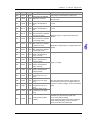
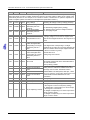
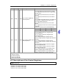
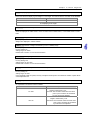
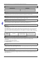
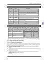
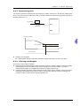
1
Industrial Automation Headquarters Delta Electronics, Inc. Taoyuan Technology Center No.18, Xinglong Rd., Taoyuan City, Taoyuan County 33068, Taiwan TEL: 886-3-362-6301 / FAX: 886-3-371-6301 Asia Delta Electronics (Jiangsu) Ltd. Wujiang Plant 3 1688 Jiangxing East Road, Wujiang Economic Development Zone Wujiang City, Jiang Su Province, P.R.C. 215200 TEL: 86-512-6340-3008 / FAX: 86-769-6340-7290 Delta Greentech (China) Co., Ltd. 238 Min-Xia Road, Pudong District, ShangHai, P.R.C. 201209 TEL: 86-21-58635678 / FAX: 86-21-58630003 Delta Electronics (Japan), Inc. Tokyo Office 2-1-14 Minato-ku Shibadaimon, Tokyo 105-0012, Japan TEL: 81-3-5733-1111 / FAX: 81-3-5733-1211 Delta Electronics (Korea), Inc. 1511, Byucksan Digital Valley 6-cha, Gasan-dong, Geumcheon-gu, Seoul, Korea, 153-704 TEL: 82-2-515-5303 / FAX: 82-2-515-5302 DVP201/202/211LC-SL Load Cell Module Operation Manual Delta Electronics Int’l (S) Pte Ltd. 4 Kaki Bukit Ave 1, #05-05, Singapore 417939 TEL: 65-6747-5155 / FAX: 65-6744-9228 Delta Electronics (India) Pvt. Ltd. Plot No 43 Sector 35, HSIIDC Gurgaon, PIN 122001, Haryana, India TEL : 91-124-4874900 / FAX : 91-124-4874945 Americas Delta Products Corporation (USA) Raleigh Office P.O. Box 12173,5101 Davis Drive, Research Triangle Park, NC 27709, U.S.A. TEL: 1-919-767-3800 / FAX: 1-919-767-8080 Delta Greentech (Brasil) S.A. Sao Paulo Office Rua Itapeva, 26 - 3° andar Edificio Itapeva One-Bela Vista 01332-000-São Paulo-SP-Brazil TEL: 55 11 3568-3855 / FAX: 55 11 3568-3865 Europe Deltronics (The Netherlands) B.V. Eindhoven Office De Witbogt 20, 5652 AG Eindhoven, The Netherlands TEL: 31-40-2592850 / FAX: 31-40-2592851 DVP-0051720-01 *We reserve the right to change the information in this manual without prior notice. 2014-09-26 www.deltaww.com DVP201/202/211LC-SL Load Cell Module Operation Manual Table of Contents Chapter 1 Introduction 1.1 Principle of a Load Cell................................................................1-2 1.2 Introduction of a Load Cell ..........................................................1-2 1.3 Functional Specifications .............................................................1-2 Chapter 2 Dimensions and Profile 2.1 Dimensions ...............................................................................2-2 2.2 Profile ......................................................................................2-2 2.3 Arrangement of the Terminals .....................................................2-3 2.4 Description of the Indicators........................................................2-3 Chapter 3 Installation and Wiring 3.1 Installation ...............................................................................3-2 3.1.1 Connecting a Load Cell Module to a DVP-SV series PLC ..............3-2 3.1.2 Installing a DVP-SV series PLC and a Load Cell Module on a DIN rail.....................................................................................3-2 3.2 Communication .........................................................................3-3 3.3 External Wiring..........................................................................3-4 3.4 Selecting a Load Cell Sensor........................................................3-6 Chapter 4 Control Registers 4.1 Table of Control Registers ...........................................................4-2 4.2 Descriptions of the Control Registers ............................................4-5 4.3 Descriptions of Functions ............................................................4-9 4.3.1 Measuring a Net Weight ........................................................4-9 4.3.2 Stability Check .................................................................. 4-10 4.3.3 Determining Zero............................................................... 4-11 4.3.4 Filtering out Weights .......................................................... 4-11 4.3.5 Correspondence between Current Outputs and Weights ........... 4-12 Chapter 5 Making Adjustment 5.1 Steps in Adjusting Points.............................................................5-3 i 5.2 Example 1 ................................................................................ 5-4 5.3 Example 2 ................................................................................ 5-5 ii Chapter 1 Introduction Table of Contents 1.1 1.2 1.3 Principle of a Load Cell................................................................1-2 Introduction of a Load Cell ..........................................................1-2 Functional Specifications .............................................................1-2 1-1 D V P 2 0 1 / 2 0 2 / 2 11 L C - S L L o a d C e l l M o d u l e O p e r a t i o n M a n u a l Thanks for using the load cell module DVP201/202/211LC-SL. To ensure that the product is correctly installed and operated, users need to read the operation manual carefully before they use DVP201/202/211LC-SL. The operation manual provides functional specifications, and introduces installation, basic operation and setting, and the usage of DVP201/202/211LC-SL. DVP201/202/211LC-SL is an OPEN-TYPE device. It should be installed in a control cabinet free of airborne dust, humidity, electric shock and vibration. To prevent non-maintenance staff from operating DVP201/202/211LC-SL, or to prevent an accident from damaging DVP201/202/211LC-SL, the control cabinet in which DVP201/202/211LC-SL is installed should be equipped with a safeguard. For example, the control cabinet in which DVP201/202/211LC-SL is installed can be unlocked with a special tool or key. DO NOT touch any terminal when DVP201/202/211LC-SL is powered up. In order to prevent the product from being damaged, or prevent staff from being hurt, users need to read the operation manual carefully, and follow the instructions in the manual. 1.1 Principle of a Load Cell If a metallic material undergoes tension or strain, it will become thin, and its electrical impedance will increase. If a metallic material is compressed, its electrical impedance will become small. A strain gauge adopting this principle is called a load cell. Such sensing device is able to convert physical pressure into electrical signals, and therefore it is widely used on occasions on which loads, tension and pressure need to be converted into electrical signals. 1.2 Introduction of a Load Cell A load cell module provides 24-bit resolution applicable to 4-wire or 6-wire load cells with various eigenvalues. Therefore, its response time can be adjusted according to users’ requirements. On this basis, the requirements of load application markets can be easily met. Besides, a DVP series PLC* can read data in a load cell module or write data to a load cell module by means of the instruction FROM/TO. *: DVP-SV series PLCs, DVP-EH2-L series PLCs, DVP-SA2 series PLCs, and DVP-SX2 series PLCs support left-side extension modules. 1.3 Functional Specifications Load cell module Rated supply voltage/Power consumption Static minimum/maximum voltage Dynamic minimum/maximum voltage Maximum current consumption Input signal range Sensibility ADC resolution Highest precision Communication interface Applicable sensor type Expanding a temperature coefficient Reducing a temperature coefficient to zero Linearity error Response time Eigenvalue applicable to a load cell 1-2 DVP201/202/211LC-SL Voltage output 24 V DC (-15 to +20%)/5 W 20.4 V/28.8 V DC 18.5 V/30.2 V DC 150 mA ±200 mV DC +5 V DC +/-5% 24 bits 0.04% RS-232, RS-485 4-wire or 6-wire load cell ≤ ± 20 ppm/K v. E ≤ ± 0.1 μV/K ≤ 0.015% 2.5, 10, 16, 20, 50, 60, 100, 200, and 400ms 0~1, 0~2, 0~4, 0~6, 0~20, 0~40 and 0~80 mV/V Chapter 1 Introduction Load cell module Maximum distance for connecting a load cell Maximum output current Allowable load Averaging weights Common-mode rejection ratio (CMRR @50/60 Hz) DVP201/202/211LC-SL Voltage output 100 meters 5 V DC * 300 mA 40~4,010 Ω 100 ≥100 dB Between a digital circuit and the ground: 500 V AC Between an analog circuit and the ground: 500 V AC Between an analog circuit and a digital circuit: 500 V AC Load cell modules can be connected to the left side of a PLC. The Connecting to a DVP series PLC modules connected to a PLC are numbered from 100 to 107 according to the closeness to the PLC. Operation: 0~55°C (temperature), 5~95% (humidity), pollution degree 2 Operation/Storage Storage: -25~70°C (temperature), 5~95% (humidity) International standards: IEC 61131-2, IEC 68-2-6 (TEST Fc)/IEC 61131-2 Vibration/Shock resistance & IEC 68-2-27 (TEST Ea) Isolation DVP211LC-SL Electrical specifications for input Electrical specifications for output terminals terminals Input/Output terminal X0, X1 Y0, Y1, Y2, Y3 Type Digital input Transistor Form DC (sinking or sourcing) -Specifications Input current: 24 V DC, 5 mA Voltage specifications: 5~30 V DC #1 Input impedance 4.7 KΩ -Maximum switch frequency 10 kHz 1 kHz Off → On > 15 V DC -Action level On → Off < 5 V DC -Response Off → On < 20 μs < 100 μs time On → Off < 50 μs < 150 μs Resistive load -0.5 A/output (4 A/COM)#2 Maximum Inductive load -15 W (30 V DC) load Bulb -2.5 W (30 V DC) Note: In order to meet DIN 1319-1, an error needs to be less than or equal to 0.05% at 20 °C + 10 K. #1: UP and ZP should be connected to a 24 V DC power supply. The current that an output terminal consumes is approximately 1 mA. #2: In an NPN mode, ZP is used. In a PNP mode, UP is used. 1-3 D V P 2 0 1 / 2 0 2 / 2 11 L C - S L L o a d C e l l M o d u l e O p e r a t i o n M a n u a l MEMO 1-4 Chatper 2 Dimensions and Profile Table of Contents 2.1 2.2 2.3 2.4 Dimensions ...............................................................................2-2 Profile ......................................................................................2-2 Arrangement of the Terminals ......................................................2-3 Description of the Indicators........................................................2-3 2-1 D V P 2 0 1 / 2 0 2 / 2 11 L C - S L L o a d C e l l M o d u l e O p e r a t i o n M a n u a l 3 mm 2.1 Dimensions DVP211LC POWER EXC+ RUN EXC- ERROR SIG+ L.V SIGSEN+ SEN- MOTION SHD LOOP A0+ X0 A0 - 90 mm X1 X0 X1 UP Y0 ZP Y1 Y0 Y2 Y1 Y3 Y2 Y3 33 mm 60 mm Unit: mm 2.2 Profile DVP211LC POWER RUN ERROR L.V EXC+ EXCSIG+ SIGSEN+ SEN- MOTION SHD LOOP A0+ X0 A0 - X1 X0 X1 UP Y0 ZP Y1 Y0 Y2 Y1 Y3 Y2 Y3 1. Mounting hole 3. Extension port POWER indicator, RUN indicator, ERROR 5. indicator and L.V indicator 7. I/O terminals 9. DIN rail clip 11. Power input 2-2 2. Mounting groove (35mm) 4. I/O module clip MOTION indicator, LOOP indicator, DI (X0, X1)/DO 6. (Y0-Y3) indicators 8. RS-232 port 10. RS-485 port Chapter 2 Dimensions and Profile 2.3 Arrangement of the Terminals EXC+ EXC- SIG+ SIG- SEN+ SEN- SHD SEN+ SEN- SHD SEN+ SEN- SHD DVP201LC-S L EXC+ EXC- SIG+ SIG- EXC+ EXC- SIG+ SIG- SEN+ SEN- SHD DVP202LC-S L EXC+ EXC- SIG+ SIG- AO+ AO- S/S X0 X1 UP ZP Y0 Y1 Y2 Y3 DVP211 LC-S L 2.4 Description of the Indicators Name POWER indicator RUN indicator ERROR indicator L.V indicator LOOP indicator Motion indicator X0 indicator/X1 indicator Y0 indicator/Y1 indicator/ Y2 indicator/Y3 indicator Color Green Green Red Red Green Orange Red Red Function Displaying power Displaying the status of the module Displaying an error Showing that the voltage of the an external power is low Loop control Showing that measurement is stable Showing that X0/X1 is On/Off Showing that Y0/Y1/Y2/Y3 is On/Off 2-3 D V P 2 0 1 / 2 0 2 / 2 11 L C - S L L o a d C e l l M o d u l e O p e r a t i o n M a n u a l MEMO 2-4 Chapter 3 Installation and Wiring Table of Contents 3.1 Installation ...............................................................................3-2 3.1.1 Connecting a Load Cell Module to a DVP-SV series PLC..............3-2 3.1.2 Installing a DVP-SV series PLC and a Load Cell Module on a DIN rail.....................................................................................3-2 3.2 Communication .........................................................................3-3 3.3 External Wiring..........................................................................3-4 3.4 Selecting a Load Cell Sensor........................................................3-6 3-1 D V P 2 0 1 / 2 0 2 / 2 11 L C - S L L o a d C e l l M o d u l e O p e r a t i o n M a n u a l 3.1 Installation 3.1.1 Connecting a Load Cell Module to a DVP-SV series PLC Pull the I/O module clips on a DVP-SV series PLC. Insert the points in the corner of a load cell module into the four holes in the DVP-SV series PLC. Please see step in the figure below. Press the I/O module clips on the DVP-SV series PLC, and make sure that the load cell module is tightly connected to the DVP-SV series PLC. Please see step in the figure below. 2 DV P28SV DVP211LC - 1 RU N ST OP 2 3.1.2 Installing a DVP-SV series PLC and a Load Cell Module on a DIN rail Please use a 35 mm DIN rail. Pull the DIN rail clips on a DVP-SV series PLC and a load cell module. Install the DVP-SV series PLC and the load cell module on the DIN rail. Press the DIN rail clips on the DVP-SV series PLC. Please see the figure below. D V P2 11 L C 35 mm DIN rail 3-2 Chapter 3 Installation and Wiring 3.2 Communication Please wire a load cell module according to the definitions of the pins in a communication connector. PC COM Port 9 PIN D-SUB female Rx 2 Tx 3 GND 5 7 8 1 4 6 DVP211LC COM Port 8 PIN MINI DIN 5 4 8 1,2 Tx Rx GND 5V 2 5 8 1 4 7 3 6 There are 2 communication interfaces in a load cell module which can communicate with a PC or other devices. COM1 is an RS-232 port, and COM2 is an RS-485 port. Both ports meet the standard MODBUS protocol. A PC can directly communicate with a load cell module through COM1. Delta power supply modules are highly recommended. RS232 RS-232 3-3 D V P 2 0 1 / 2 0 2 / 2 11 L C - S L L o a d C e l l M o d u l e O p e r a t i o n M a n u a l 3.3 External Wiring F our -wir e EX C+ A+5V EX C- AGND SIG+ SIG- CH1 SE N+ SE N- Six- wire EX C+ A+5V EX C- AGND SIG+ SIG- CH 2 SE N+ SE N- Connected to on a power sup ply m odule *1 System ground 0V 24V T hir d gr ound ( Im pedance: Less than 100 3-4 ) DC/DC conver ter A+5V AGND Chapter 3 Installation and Wiring Multiple load cells connected in parallel are connected to a single load cell module. Load cell Load cell DVP202LC Load cell CH1 Load cell CH2 Load cell Load cell Load cell Load cell Note 1: Please connect on a power supply module and on the load cell module to a system ground, and then ground the system ground or connect the system ground to a distribution box. Note 2: If multiple load cells are connected in parallel, the total impedance should be greater than 40 Ω. 3-5 D V P 2 0 1 / 2 0 2 / 2 11 L C - S L L o a d C e l l M o d u l e O p e r a t i o n M a n u a l 3.4 Selecting a Load Cell Sensor 1. Exciting voltage: 2. 3. 4. 5. 3-6 An excitation voltage is external power provided for a load cell sensor. The maximum voltage that a sensor can accept is specified in the specifications for the sensor. The exciting voltage that a load cell module provides is +5 V, and therefore a sensor which can accept a voltage greater than 5 V can be used. Eigenvalue A load cell sensor uses a bridge circuit. If a load cell is under pressure, SIG+ and SIG- will output voltages which are in proportion to force. An eigenvalue determines the characteristics of the output of a load cell sensor. The unit used is mV/V. If a load cell receives external force, it will output low voltage. Output a sensor: (Force/Maximum rated load)×(Exciting voltage×Eigenvalue) Example: The eigenvalue of a sensor is 2 mV/V, and the maximum rated load of the sensor is 10 kg. The voltage provided by a module is 5 V. The voltage to which the maximum rated load corresponds is 10 mV. If the load of the sensor is 1 kg, the voltage that the sensor outputs will be 1 mV. The eigenvalue that the module can support is 80 mV/V. The sensors whose eigenvalues are less than 80 mV/V can be used. Maximum rated load When users select a load cell module, they have to consider factors such as loads, tares, vibrations, and shocks. The closer the load on a load cell sensor is to the maximum rated load specified in the specifications for the load cell sensor, the more accurately the load is measured. Four-wire configuration/Six-wire configuration There are two ways to wire a load cell sensor. They are a four-wire configuration and a six-wire configuration. A load cell module provides power for a load cell sensor by means of EXC+/EXC-. However, there is impedance between the load cell module and the sensor. The voltage that the sensor actually receives is less than the voltage provided by the module. The output terminals SIG+ and SIG- on a sensor have relations with the voltages received. If the distance between a module and a sensor is short, the impedance between the module and the sensor will be small, and a four-wire configuration can be adopted. If the distance between a module and a sensor is long, a six-wire configuration can be used to reduce the error resulting from the impedance between the module and the sensor. Estimating precision The precision of a load cell module is 0.04%. The maximum rated load of a load cell sensor multiplied by 0.04% is the maximum precision that a load cell module can resolve. (The measurement time set by default is 50 milliseconds.) If the measurement time set is longer, the precision presented will increase. When users select a load cell sensor, they have to check whether the conversion time of the load cell sensor and the precision of the load cell sensor meet their requirements. Chapter 4 Control Registers Table of Contents 4.1 Table of Control Registers............................................................4-2 4.2 Descriptions of the Control Registers ............................................4-5 4.3 Descriptions of Functions ............................................................4-9 4.3.1 Measuring a Net Weight ...........................................................4-9 4.3.2 Stability Check ..................................................................... 4-10 4.3.3 Determining Zero.................................................................. 4-11 4.3.4 Filtering out Weights ............................................................. 4-11 4.3.5 Correspondence between Current Outputs and Weights .............. 4-12 D V P 2 0 1 / 2 0 2 / 2 11 L C - S L L o a d C e l l M o d u l e O p e r a t i o n M a n u a l 4.1 Table of Control Registers CR# Address Attribute Register name #0 H1000 O R Model name #1 H1001 O R Firmware version #2 H1002 O R/W Characteristic value #3 H1003 O R/W Reaction time for measurement #6 H1006 X R/W Returning to zero/Subtracting a tare #7 H1007 O R/W Displaying a gross weight/net weight #8 H1008 O R/W #9 H1009 O R/W #10 H100A O R/W #11 H100B O R/W #12 H100C X R #13 H100D X R #14 H100E X R #15 H100F X R #16 H1010 O R/W #17 H1011 O R/W #18 #19 H1012 H1013 O R/W O R/W 4-2 Tare measured by CH1 (Low word) Tare measured by CH1 (High word) Tare measured by CH2 (Low word) Tare measured by CH2 (High word) Weight measured by CH1 (Low word) Weight measured by CH1 (High word) Weight measured by C2 (Low word) Weight measured by C2 (High word) Number of weights measured by CH1 in a stability range Number of weights measured by CH2 in a stability range Stability range for CH1 Stability range for CH2 Explanation The model code of a load cell module is defined by the module’s system. DVP201LC-SL’s model code=H’5106 DVP202LC-SL’s model code=H’5206 DVP211LC-SL’s model code=H’5906 Hexadecimal value The current firmware version of a load cell module is displayed. CH1: Bit 0~bit 7; CH2: Bit 8~bit 15 Mode 0: 1 mV/V; Mode 4: 20 mV/V Mode 1: 2 mV/V; Mode 5: 40 mV/V Mode 2: 4 mV/V; Mode 6: 80 mV/V Mode 3: 6 mV/V CH1: bit0~bit7; CH2: bit8~bit15 Mode 0: 2.5ms; Mode 5: 60ms Mode 1: 10ms; Mode 6: 100ms Mode 2: 16ms; Mode 7: 200ms Mode 3: 20ms; Mode 8: 400ms Mode 4: 50ms (factory setting) K1: Subtracting the tare K4: Subtracting the tare measured by CH2 measured by CH1 K5: Not subtracting the K2: Not subtracting the tare measured by CH2 tare measured by CH1 K3: Restoring the weight K6: Restoring the weight measured by CH2 to measured by CH1 to zero zero CH1: Bit 0~bit 7; CH2: Bit 8~bit 15 K0: Displaying a gross weight K1: Displaying a net weight Displaying a tare Displaying a weight Setting range: K1~K500 (Factory setting: K5) Setting range: K1~K500 (Factory setting: K5) Setting range: K1~K10000 (Factory setting: K10) Setting range: K1~K10000 (Factory setting: K10) Chapter 4 Control Registers CR# Address Attribute #25 H1019 #26 H101A #27 H101B #28 H101C #29 H101D #30 H101E #31 H101F #32 H1020 #33 H1021 #34 H1022 #35 H1023 #36 H1024 #37 H1025 #38 H1026 #39 H1027 #40 H1028 #41 H1029 Register name Total number of points O R/W which need to be adjusted X R/W Adjustment command Selecting a point which O R/W needs to be adjusted for CH1 Selecting a point which O R/W needs to be adjusted for CH2 Digital value given to a point O R/W which needs to be adjusted for CH1 (Low word) Digital value given to a point O R/W which needs to be adjusted for CH1 (High word) Digital value given to a point O R/W which needs to be adjusted for CH2 (Low word) Digital value given to a point O R/W which needs to be adjusted for CH2 (High word) Weight of a point which O R/W needs to be adjusted for CH1 (Low word) Weight of a point which O R/W needs to be adjusted for CH1 (High word) Weight of a point which O R/W needs to be adjusted for CH2 (Low word) Weight of a point which O R/W needs to be adjusted for CH2 (High word) Maximum which can be O R/W measured by CH1 (Low word) Maximum which can be O R/W measured by CH1 (High word) Maximum which can be O R/W measured by CH2 (Low word) Maximum which can be O R/W measured by CH2 (High word) X R/W Storing all setting values (H’5678) Explanation Setting range: K2~K20 (Factory setting: K2) CH1: K1~K20 CH2: K21~K40 K1~K19 K1~K19 Digital value given to a point which needs to be adjusted Digital value corresponding to a weight needs to be adjusted Weight of a weight Users can specify the maximum weight which can be measured by CH1/CH2. If a weight measured exceeds the maximum weight, an error code will be stored. Storing all setting values, and writing them to the flash memory in the load cell module used H0: No action (factory setting) H’FFFF: All setting values are stored successfully. H’5678: Writing all setting values to the flash memory in the load cell module used 4-3 D V P 2 0 1 / 2 0 2 / 2 11 L C - S L L o a d C e l l M o d u l e O p e r a t i o n M a n u a l CR# Address Attribute Register name Explanation CR#41: If the value in CR#41 is H’5678, all setting values will be stored in the flash memory. After the setting values are stored, the value in CR#41 will become H’FFFF. If the value written to CR#41 is not H’5678, it will automatically become H’0. For example, if H1 is written to CR#41, it will become H1. (After the adjustment of points is complete, please use CR#41 to make adjustment parameters retentive.) Restoring all settings to Restoring all settings to factory settings (H’55AA) #42 H102A X R/W factory settings Way in which weights #43 H102B X R/W measured by CH1 are K0: Not filtering weights (factory setting) filtered out K1: Filtering out the maximum weight measured Way in which weights K2: Averaging weights #44 H102C X R/W measured by CH2 are filtered out #45 H102D X R/W Filter parameter for CH1 Filtering out the maximum weight measured: K0~K8 Averaging weights: The number of weights which need to be averaged should be in the range of K1 to #46 H102E X R/W Filter parameter for CH1 K100. Range for determining whether the digital value If the digital value corresponding to a weight #48 H1030 O R/W corresponding to a weight measured by CH1/CH2 is in the range specified, bit measured by CH1 is 0 5/bit 10 in CR#51 will be set (the weight measured grams is will be counted as 0 grams). Range for determining Default value: K10 whether the digital value Setting range: K0~K32767 #49 H1031 O R/W corresponding to a weight measured by CH2 is 0 grams The status of the load cell module used is stored in this register. Please refer to the status table below #51 H1033 X R/W Status code for more information. Factory setting: H’0000 The default value in CR#52/CR#54 is K1. The #52 H1034 O R/W RS-232 station address setting values in CR#52 and CR#54 should be in RS-232 communication #53 H1035 O R/W the range of K1 to K255. The default value in format CR#53/CR#55 is H’0000 (ASCII, 9600 bps, 7 data #54 H1036 O R/W RS-485 station address bits, even parity bit, one stop bit). Please refer to the RS-485 communication communication format table below for more #55 H1037 O R/W format information. #100 H1064 X R/W Current output Setting range: K0~K4000 #101 H1065 X R Digital input terminal Bit 0: X0; Bit 1: X1 #102 H1066 X R/W Digital output terminal Bit 0: Y0; Bit 1: Y1; Bit 2: Y2; Bit 3: Y3 K0: Digital value corresponding to a current output in the range of 0 mA to 20 mA (factory setting) K1: Digital value corresponding to a current output in the range of 4 mA to 20mA #103 H1067 O R/W Way of outputting a current K2: Weight corresponding to a current output in the range of 0 mA to 20mA K3: Weight corresponding to a current output in the range of 4 mA to 20mA 4-4 Chapter 4 Control Registers CR# Address Attribute #104 H1068 #105 H1069 Register name Explanation X0: Bit 0~bit 7; X1: Bit 8~bit 15 H0: General digital input terminal (factory setting) H1: If a digital input terminal is ON, a weight will be restored to zero, H2: If a digital input terminal is ON, a tare will be measured. H3: If a digital input terminal is ON, a tare will be Way in which a digital input subtracted. O R/W H4: If a digital input terminal is OFF, a net weight will terminal operates be measured. If a digital input terminal is ON, a gross weight will be measured. H6: If a digital input terminal is ON, zero will be adjusted. H7: If a digital input terminal is ON, the first point will be adjusted. X0 and X1 can not be set to H4 simultaneously. Bit 15~bit 12 Bit 11~bit 8 Bit 7~bit 4 Bit 3~bit 0 Y3 Y2 Y1 Y0 H0: General digital output terminal (factory setting) H1: If no weight is measured, a digital output terminal will be ON. H2: If no weight is measured, a digital output terminal will be OFF. H3: If a weight measured is greater than the maximum weight specified, a digital output terminal will be ON. Way in which a digital output O R/W H4: If a weight measured is greater than the terminal operates maximum weight specified, a digital output terminal will be OFF. H5: If an excitation voltage is abnormal, a digital output terminal will be ON. H6: If an excitation voltage is abnormal, a digital output terminal will be OFF. H7: If a weight measured is in the stability range specified, a digital output terminal will be ON. H8: If a weight measured is in the stability range specified, a digital output terminal will be OFF. Symbols: O: Retentive register X: Unretentive register R: Users can read data. W: Users can write data. 4.2 Descriptions of the Control Registers C R # 0 : Model name [Description] DVP201LC-SL’s model code=H’5106 DVP202LC-SL’s model code=H’5206 DVP211LC-SL’s model code=H’5906 4-5 D V P 2 0 1 / 2 0 2 / 2 11 L C - S L L o a d C e l l M o d u l e O p e r a t i o n M a n u a l C R # 1 : Firmware version [Description] High byte: Number at the left side of the decimal point in a version number Low byte: Number at the right side of the decimal point in a version number Example: V1.01→CR#=H’0101 C R # 2 : Eigenvalue [Description] The specifications for load cells vary from brand to brand. Users need to set an eigenvalue according to the specification for the load cell used. Eigenvalue Specifications for the Selection of an eigenvalue Setting value in CR#2 eigenvalue in a load cell 0mV/V<Eigenvalue≦1 mV/V 1m V/V H’0000 1mV/V<Eigenvalue≦2 mV/V 2m V/V H’0001 (Default setting) 2mV/V<Eigenvalue≦4 mV/V 4m V/V H’0002 4mV/V<Eigenvalue≦6 mV/V 6m V/V H’0003 6mV/V<Eigenvalue≦20 mV/V 20m V/V H’0004 20mV/V<Eigenvalue≦40 mV/V 40m V/V H’0005 40mV/V<Eigenvalue≦80 mV/V 80m V/V H’0006 Eigenvalue>80 mV/V Not supported C R # 3 : Reaction time for measurement [Description] Users can set the time which needs to elapse before a weight is sampled. The shorter the time set is, the shorter the time it takes to filter weights. The weights measured are not in a stability range. If the time set is the maximum time which can be set, the weights measure will be in a stability range. Reaction time for measurement Input value Description Mode 0: H’0000 2.5 ms Mode 1: H’0001 10 ms Mode 2: H’0002 16 ms Mode 3: H’0003 20 ms Mode 4: H’0004 50ms (Default setting) Mode 5: H’0005 60 ms Mode 6: H’0006 100 ms Mode 7: H’0007 200 ms Mode 8: H’0008 400 ms C R # 6 : Returning to zero/Subtracting a tare [Description] Users can use CR#6 to restore the weight measured to zero. Input value Description K1 Subtracting the tare measured by CH1 K2 Not subtracting the tare measured by CH1 K3 Restoring the weight measured by CH1 to zero K4 Subtracting the tare measured by CH2 K5 Not subtracting the tare measured by CH2 K6 Restoring the weight measured by CH2 to zero 4-6 Chapter 4 Control Registers C R # 7 : Displaying a gross weight/net weight [Description] Users can choose to display a gross weight or a net weight. The channel which is not used can be disabled. Bit 15~bit 8 Bit 7~bit 0 CH2 CH1 K0: Displaying a gross weight K1: Displaying a net weight C R # 8 ~ 11 : Tare measured by CH1/CH2 [Description] Tares are displayed in CR#8~CR#11. Users can write tares to CR#8~CR#11, or use CR#8~CR#11 to read tares. C R # 1 2 ~ 1 5 : Weight measured by CH1/CH2 [Description] Weights are displayed in CR#12~CR#15. C R # 1 6 ~ 1 7 : Number of weights measured by CH1 in a stability range [Description] Factory setting: K5 Setting range: K1~K500 Please refer to section 4.3.2 for more information. C R # 1 8 ~ 1 9 : Stability range for CH1/CH2 [Description] Factory setting: K10 Setting range: K1~K10,000 Please refer to section 4.3.2 for more information. C R # 2 5 : Total number of points which need to be adjusted [Description] Factory setting: K2 Setting range: K2~K20 Users generally adjust two points, but they can adjust several points. The maximum number of points which can be adjusted is 20. C R # 2 6 : Adjustment command [Description] An adjustment command is stored in CR#26. Command value K1~K20 K21~40 Description of CR#26 K1: The command value is used when no weight is measured by CH1. K2~K20: The command values are used when point 1~point 19 which are measured by CH1 need to be adjusted. K21: The command value is used when no weight is measured by CH2. K22~K40: The command values are used when point 1~point 19 which are measured by CH2 need to be adjusted. 4-7 D V P 2 0 1 / 2 0 2 / 2 11 L C - S L L o a d C e l l M o d u l e O p e r a t i o n M a n u a l C R # 2 7 ~ 2 8 : Selecting a point which needs to be adjusted for CH1/CH2 [Description] Command value K1~K19 K1~K19 Description Selecting point 1~point 19 for CH1 Selecting point 1~point 19 for CH2 C R # 2 9 ~ 3 2 : Digital value given to a point which needs to be adjusted for CH1/CH2 [Description] The digital values given to points which need to be adjusted are displayed in CR#29~CR#32. C R # 3 3 ~ 3 6 : Weight of a point which needs to be adjusted for CH1/CH2 [Description] The weights of points which need to be adjusted are written to CR#33~CR#36. C R # 3 7 ~ 4 0 : Maximum weight which can be measured by CH1/CH2 [Description] Users can specify the maximum weight which can be measured by CH1/CH2. If the weight measured by CH1/CH2 exceeds the maximum weight specified, bit 4/bit 9 in CR#51 will be set to 1. C R # 4 1 : Storing all setting values [Description] CR#41 is used to store all setting values, and write them to the flash memory in the load cell module used. Factory setting: 0 If the value in CR#41 is H’5678, all setting values will be stored in the flash memory in the load cell module used. After the setting values are stored, the value in CR#41 will become H’FFFF. If the value written to CR#41 is not H’5678, it will automatically become H’0. For example, if H’1 is written to CR#41, it will become H’0. Description H’0 H’FFFF H’5678 Writing all setting values All setting values are to the flash memory in Setting No action stored successfully. the load cell module used C R # 4 3 ~ 4 4 : Way in which weights measured by CH1/CH2 are filtered out [Description] Users can set a way in which weights measured by CH1/CH2 are filtered out according to their requirements. K0: Not filtering weights (factory setting) K1: Filtering out the maximum weight measured K2: Averaging weights C R # 4 5 ~ 4 6 : Filter parameter for CH1/CH2 [Description] Filtering out the maximum weight measured: K0~K8 Averaging weights: The number of weights which need to be averaged should be in the range of K1 to K100. C R # 4 8 ~ 4 9 : Range for determining whether the digital value corresponding to a weight measured by CH1/CH2 is 0 grams [Description] If the digital value corresponding to a weight measured by CH1/CH2 is in the range specified, bit 5/bit 10 in CR#51 will be set to 1. 4-8 Chapter 4 Control Registers C R # 5 1 : Status code [Description] Bit number Bit 0 Bit 1 Value H’0001 H’0002 Bit 2 H’0004 Bit 3 H’0008 Bit 4 H’0010 Bit 5 Bit 6 H’0020 H’0040 Bit 7 H’0080 Bit 8 H’0100 Bit 9 H’0200 Bit 10 Bit 11 Bit 12~bit 15 H’0400 H’0800 Description Abnormal power Hardware failure The weight measured by CH1 exceeds the maximum weight which can be measured, or the voltage of SEN is incorrect. CH1 is adjusted incorrectly. The weight measured by CH1 exceeds the maximum weight which can be measured. No weight is measured by CH1. A weight measured by CH1 is in the stability range specified. The conversion of a weight measured by CH2 into a digital value is incorrect, or the voltage of SEN is incorrect. CH2 is adjusted incorrectly. The weight measured by CH2 exceeds the maximum weight which can be measured. No weight is measured by CH2. A weight measured by CH2 is in the stability range specified. Reserved C R # 5 2 ~ 5 5 : Setting RS-232/RS-485 communication [Description] Bit 15 ACSII/RTU Bit 15 Bit 7~bit 4 Bit 3 Bit 2 Bit 1~bit 0 Bit 14~Bit 8 Reserved Bit 7 Bit 6 Bit 5 Bit 4 Bit 3 Serial transmission speed Data length Description ACSII/RTU 0 ACSII 0 9,600 bps Serial transmission speed 2 38,400 bps 4 115,200 bps Data length (RTU=8 bits) 0 7 Stop bit 0 1 bit 0 Even Parity bit 2 Reserved Bit 2 Stop bit 1 1 3 5 1 1 1 3 Bit 1 Bit 0 Parity bit RTU 19,200 bps 57,600 bps Reserved 8 2 bits Odd Reserved Example: If RS-232 communication format is “115200, 7, E, 1, ASCII”, the value in CR#53 will be H’0400. 4.3 Descriptions of Functions 4.3.1 Measuring a Net Weight Users can choose to measure the net weight or the gross weight of an object. A net weight is the weight of a product, that is, the actual weight of a product without its package. The weight of a package is a tare. A gross weight is a total weight, namely a net weight plus a tare. Tare: A tare is the weight of a package Net weight: A net weight is the weight of a product, that is, the actual weight of a product without its package. Gross weight: A gross weight is a total weight, namely the weight of a product itself (a net weight) plus the weight of a package (a tare). Gross weight=Net weight+Tare Example: A product weighs 10 kilograms, and the carton in which the product is packed weighs 0.2 kilograms. The total weight gotten is 10 kilograms. Net weight=10 kg Tare=0.2 kg 4-9 D V P 2 0 1 / 2 0 2 / 2 11 L C - S L L o a d C e l l M o d u l e O p e r a t i o n M a n u a l Gross weight=10.2 kg Relevant control registers CR#6: Returning to zero/Subtracting a tare CR#7: Displaying a gross weight/net weight CR#8~11: Tare measured by CH1/CH2 4.3.2 Stability Check When an object is put on a load cell, users can check whether the present weight of the object is in a stability range specified. If a weight measured is in a stability range specified by users (CR#18/CR#19), bit 6/bit 11 in CR#51 will be set to 1. If a weight measured exceeds a range specified by users (CR#18/CR#19), bit 6/bit 11 in CR#51 will be set to 0. Bit 6/Bit 11 in CR#51 will not be set to 1 until the number of weights measured in a stability range reaches the value in CR#16/CR17. Example: The measurement time set is 10 milliseconds, the number of weights measured in a stability range is 10, and the stability range set is 1000 grams. If a variation exceeds 1000 grams, bit 6/bit 11 in CR#51 will be set to 0. If the variations in 100 milliseconds (10×10 ms) are within 1000 grams, bit 6/bit 11 in CR#51 will be set to 1. (Users should judge whether the present weight measured is in the stability range set before they perform control.) △: Variations in average weights t T: Measurement time set by users k K: Stability range set by users m M: Number of weights measured in a stability range △>>k k Average weight △> k >k △< <kk <kk △< k △< <k △> k >k △> k >k △> k >k >k △> k △ △> k >k Time Bit 6/Bit 11 in CR#51 t m bit Relevant control registers CR#16/CR#17: Number of weights measured by CH1/CH2 in a stability range CR#18/CR#19: Stability range for CH1/CH2 4-10 Chapter 4 Control Registers 4.3.3 Determining Zero If an object is removed from the load cell used, bit 6/bit 11 in CR#51 will be set to 1, bit 5/bit 10 in CR#51 will be set to 1, and users can perform the next control. (If a weight measured is in the zero range specified, bit 5/bit 10 in CR#51 will be set to 1.) DVP202LC-SL No object Ch1 Load cell CH2 Average weight Zero range Time Zero weight Relevant control registers CR#48/CR#49: Range for determining whether a weight measured by CH1/CH2 is 0 grams 4.3.4 Filtering out Weights There are two ways to filter out weights. Filtering out the maximum/minimum weight measured: If there is a maximum weight or a minimum weight, CR#45/CR#46 can be used to filter out the maximum weight or the minimum weight. If the value in CR#45/CR#46 is bigger, more weights will be filtered out. Setting range: K0~K8 Averaging weights: The values read are averaged so that a steady value is obtained. There may be peak values due to unavoidable external factors, and the average value obtained changes accordingly. The maximum number of values which can be averaged are 100. 4 - 11 D V P 2 0 1 / 2 0 2 / 2 11 L C - S L L o a d C e l l M o d u l e O p e r a t i o n M a n u a l 4.3.5 Correspondence between Current Outputs and Weights Currents outputs directly correspond to weights. Currents vary with weights. Users can set a current output mode by means of CR#103. Current output Current output 20m A 20m A 0mA K4000 K0 Digital value (CR#100) 4mA K0 (Mode 0) K4000 Digital value (CR#100) (Mode 1) Current output Current output 20m A 0mA K0 20m A Weight (CR#12/13) Maximum weight (CR#37/38) 4mA K0 (Mode 2) Weight (CR#12/13) Maximum weight (CR#37/38) (Mode 3) Example: 10 kg correspond to 20 mA. 10kg 0mA 0g 20mA A load cell module is directly connected to the left side of a DVP series PLC. The instruction TO is used to set parameters. CR#103 is set to K2, and CR#37/CR#38 is set to K10000. Please see the WPLSoft program shown below. 4-12 Chapter 5 Making Adjustment Table of Contents 5.1 5.2 5.3 Steps in Adjusting Points.............................................................5-3 Example 1 ................................................................................5-4 Example 2 ................................................................................5-5 5-1 D V P 2 0 1 / 2 0 2 / 2 11 L C - S L L o a d C e l l M o d u l e O p e r a t i o n M a n u a l The purpose of making adjustment is to make the weight measured by a cell correspond to the digital value displayed in a load cell module. Generally, two points are adjusted. After a system is set up, users can put no load on the scale. The weight measured is 0 grams when no load is put on the scale. The users can put a given weight on the scale, and set a digital value corresponding to the weight. The two points are adjusted. For example, if a load cell sensor which can measure a maximum weight of 10 kg is used, and 1 kg correspond to K1000, the curve presented will be like the one shown below. Weight 10 kg Point 1 kg K0 K1000 K10000 Digital value (LSB) Adjusting two points In addition to the adjustment of two points, a load cell supports the adjustment of multiple points (20 points at most). A characteristic curve is shown below. Weight Point 5 10 kg Point 3 1 kg K0 Point 4 Point 1 Point 2 K1000 Digital value K10000 (LSB) Adjusting multiple points 5-2 Chapter 5 Making Adjustment 5.1 Steps in Adjusting Points Entering adjustment Setting the total number of points which need to be adjusted (CR#25) No weight Writing K1 to CR#26 Selecting a point which needs to be adjusted (CR#27/28) Putting a weight and writing the weight of the weight to CR#33~CR#34/CR#35~CR#36 Writing an adjustment command to CR#26 YES Adjusting the next point NO Storing all the setting values (Writing H'5678 to CR#41) The adjustment is complete. (Users put no weight so that no weight is measured. After the users write K3 or K6 to CR#6, they can begin to use the load cell module.) 5-3 D V P 2 0 1 / 2 0 2 / 2 11 L C - S L L o a d C e l l M o d u l e O p e r a t i o n M a n u a l 5.2 Example 1 Example: One point is adjusted. (A weight which weighs 1 kg corresponds to 1000 lsb.) A load cell module is directly connected to the left side of a DVP series PLC. The instruction TO is used to make adjustment. The steps in making adjustment are as follows. Step 1: Write K2 to CR#25. Please see the WPLSoft program shown below. Step 2: Connect a load cell to a module, and put no load on the load cell. Step 3: Write H’0001 to CR#26. Please see the WPLSoft program shown below. Step 4: Select point 1 (default setting), and write H1 to CR#27. Please see the WPLSoft program shown below. Step 5: Put a standard weight which weighs 1000 g on the load cell. S ta n da r d we i g ht (1 kg ) Step 6: Write K1000 (1000 g) to CR#33. 5-4 Chapter 5 Making Adjustment Step 7: Write H2 to CR#26. Step 8: Make sure that the value displayed is correct, and make the adjustment retentive. Write H’5678 to CR#41. Please see the WPLSoft program shown below. 5.3 Example 2 Example: Three points are adjusted. A load cell module is used independently. The steps in making adjustment are as follows. Step 1: Select 3 in the The Num. of Adjustment box. The weight of the first weight is 500 g. It corresponds to 500 lsb. The weight of the second weight is 1000 g. It corresponds to 1000 lsb. The weight of the third weight is 1500 g. It corresponds to 1500 lsb. Please see the figure below. 5-5 D V P 2 0 1 / 2 0 2 / 2 11 L C - S L L o a d C e l l M o d u l e O p e r a t i o n M a n u a l Step 2: Put no load on the load cell used. Please see the figures below. 5-6 Chapter 5 Making Adjustment Step 3: Put a standard weight which weighs 500 g on the load cell used, and click Next. Please see the figure below. 5-7 D V P 2 0 1 / 2 0 2 / 2 11 L C - S L L o a d C e l l M o d u l e O p e r a t i o n M a n u a l Step 4: Type “500” in the Wight value of weights box, type “500” in the Digital value of weights box, and click Next. Please see the figures below. 5-8 Chapter 5 Making Adjustment Step 5: Put a standard weight which weighs 1000 g on the load cell used. Type “1000” in the Wight value of weights box, type “1000” in the Digital value of weights box, and click Next. Please see the figures below. 5-9 D V P 2 0 1 / 2 0 2 / 2 11 L C - S L L o a d C e l l M o d u l e O p e r a t i o n M a n u a l Step 6: Put a standard weight which weighs 1500 g on the load cell used. Type “1500” in the Wight value of weights box, type “1500” in the Digital value of weights box, and click Next. Please see the figures below. 5-10 Chapter 5 Making Adjustment Step 7: The adjustment made is complete, and a curve is displayed. Please see the figures below. 5 - 11 D V P 2 0 1 / 2 0 2 / 2 11 L C - S L L o a d C e l l M o d u l e O p e r a t i o n M a n u a l MEMO 5-12