1
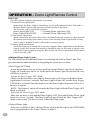
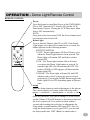
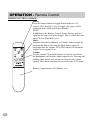
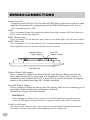
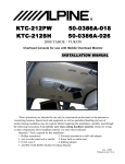
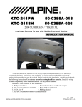
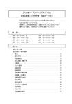
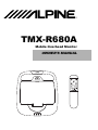
®
TMX-R680A
Mobile Overhead Monitor
OWNER’S MANUAL
PUSH
!
WARNING
It is dangerous and illegal for the driver to watch the TV/Video while
driving the vehicle. The driver may be distracted from looking ahead
and an accident could occur.
Caution
• Read this manual thoroughly before starting installation and operation. You will find a number of Safety Warnings
in this manual to tell you about things that could hurt you or other people if you were to ignore the Warnings. We
cannot be responsible for problems resulting from failure to observe the Warnings in this manual.
• This manual uses a symbol to show how to use this product safely and to avoid harm to yourself and others and
damage to your property. Here is what this symbol means. Understanding it is important for reading the Manual.
• Meaning of Symbol:
!
WARNING
This symbol means there is something that could cause serious injury or
death to you or other people.
DO NOT DISASSEMBLE OR ALTER
Attempts to disassemble or alter this product can lead to accidental fires or electrical shock.
KEEP SMALL ARTICLES OUT OF THE REACH OF CHILDREN
Keep small articles (wire-ties, etc.) out of reach of children. If swallowed, consult a physician immediately.
USE ONLY IN CARS WITH A 12 VOLT NEGATIVE GROUND
Use only in cars with a 12 volt negative (–) ground electrical system. (Check with your dealer if you are not sure.)
Failure to do so may result in fire, etc.
BEFORE WIRING, DISCONNECT THE CABLE FROM THE NEGATIVE BATTERY TERMINAL
Before doing any electrical wiring, disconnect the cable from the negative (–) terminal of the battery. Failure to do so
may result in electric shock or injury due to electrical shorts.
KEEP ELECTRICAL CABLES TOGETHER TO AVOID OPERATING HAZARDS
Dress the wiring to keep them from interfering with the operation of the steering wheel, gear lever, brake pedals, etc.
DO NOT CUT AWAY ANY WIRE INSULATION TO USE ITS POWER FOR OTHER EQUIPMENT
Tapping power from wiring to supply voltage to another piece of equipment could exceed the current carrying
capacity of that wire. This could result in fire or electric shock.
DO NOT INSTALL IN LOCATIONS WHICH MIGHT HINDER VEHICLE OPERATION
Do not install in locations which might create hazards for the vehicle occupants or hinder vehicle operation (such as
the steering wheel or gear shift) by obstructing forward vision or hampering movement etc.
DO NOT DAMAGE PIPES OR WIRING WHEN DRILLING HOLES
When drilling holes in the chassis for installation, take precautions so as not to contact, damage or obstruct pipes,
tanks or electrical wiring. Failure to take such precautions may result in fire.
DO NOT USE NUTS OR BOLTS IN THE BRAKE SYSTEM FOR INSTALLATION OR GROUND
CONNECTIONS
Never use safety-related parts such as bolts or nuts in the steering or brake systems or tanks to make wiring
installations or ground connections. Using such parts could disable control of the vehicle and cause fire etc.
HALT USE IMMEDIATELY IF A PROBLEM APPEARS
When problems appear, stop using the system immediately and contact the dealer from whom you purchased the
equipment. Some problems which may warrant immediate attention include a lack of sound, noxious odors or smoke
being emitted from the unit, or foreign objects dropped inside the unit.
DO NOT OPERATE THE EQUIPMENT OR LOOK AT THE SCREEN WHILE DRIVING
Do not change settings while driving. If operation requiring a prolonged view of the display is required, stop the
vehicle in a safe location before attempting operation.
DO NOT INSTALL THE MONITOR NEAR THE PASSENGER SEAT AIR BAG
Ensure that the location chosen for the monitor does not interfere with the operation of the passenger seat air bag.
This will prevent the triggered air bag from launching the display towards passengers, possible causing injury.
HAVE THE WIRING AND INSTALLATION DONE BY EXPERTS
The wiring and installation of this unit requires special technical skill and experience. To ensure safety, always
contact the dealer where you purchased this unit to have the work done.
DO NOT INSTALL IN LOCATIONS WITH HIGH MOISTURE OR DUST
Avoid installing the unit in locations with high incidence of moisture or dust. Moisture or dust that penetrates into this
unit may cause smoke or fire.
MAKE THE CORRECT CONNECTIONS
Failure to make the correct connections can cause fire or accident to occur.
ARRANGE THE WIRING SO IT IS NOT CRIMPED OR PINCHED
Route the cables and wiring so as not to be crimped by moving parts like seat rails or to make contact with sharp
spots which could damage the wiring.
DO NOT RAISE THE VOLUME EXCESSIVELY
Keep the volume at a level where you can still hear outside noises while driving. Driving while unable to hear outside
sounds could cause an accident.
FEATURES/DESCRIPTION
Alpine’s TMX-R680A integrates a 6.8 inch color LCD panel, infrared transmitter for wireless
headphones, dual video source selector, and remote controllable dome light. This gives the
passengers in the rear seats of your vehicle, the ability to enjoy many different A/V sources (such
as a VCR, DVD, TV Tuner and Video Game). The TMX-R680A combines all these features into a
single pod mounted to the vehicles head liner. Alpine’s SmartView™ swivel mechanism was
designed to give the rear seat passengers flexibility in adjusting the monitor for the best picture
possible from any angle.
!
WARNING
It is dangerous and illegal for the driver to watch TV/Video while driving any
vehicle. The driver may be distracted from looking ahead and an accident
could occur.
Features:
Dual A/V Inputs
Including one, 5m, mini-DIN extension to connect either of the 2 inputs to an A/V source. The
Mini-DIN to RCA interface converts the DIN input to standard RCA-type. The two inputs are
selected using the wireless remote control.
Single A/V Output
An auxiliary A/V output is provided to you to send video and audio to an additional monitor.
This signal mirrors what’s being shown on the TMX-R680A display.
Dual Headphone Outputs (wired)
Two headphone output jacks help to reduce interference from other audio sources. Infrared,
wireless headphones can also be used thanks to the built-in IR transmitter array.
Dome Light (3-way Controllable)
The integrated dome light has its own DC source (yellow/green wire). This wire, along with one
of the control wires must be connected for the Dome light to operate properly. Operation can
also be controlled through the wireless remote control. A Delayed Dome Light function can also
be programmed, if desired.
Wireless Remote Control (w/Remote Output for external source)
IR Transmitter for wireless headphones
Wireless IR Headphone (SHS-N101) compatible
Variable Audio Output
OSD (On-screen Display)
Note:
If you have any questions regarding the application of this device, see your authorized Alpine
dealer.
It is recommended that this product be used with Alpine’s various Overhead Consoles. Your
authorized Alpine dealer will have more information on these products.
See page 14 for a typical Entertainment system using the TMX-R680A.
4
OPERATION - Overhead Monitor
Headphone
Outputs (2)
SmartView Swivel
Mechanism
LCD Monitor
Panel
Monitor Open
Button
PUSH
Dome Light
IR Sensor/Logo
Headphone Outputs
Two output jacks (mini-phono plug) are provided for wired headphones. Output level is adjusted
using the Volume UP/DN buttons on the remote control.
NOTE:
• Plugging a headphone into either jack will mute the Variable Audio Output.
SmartView Swivel Mechanism
The design of this mechanism provides the rear seat passengers a stable picture, viewable from
many different angles. This system allows the LCD to tilt from 90 to 120 degrees in 10 degree
steps. At the same time, the LCD will maintain its horizontal view while being rotated from left
to right, up to 30 degrees, in 10 degree steps.
NOTE:
• The LCD will only close when rotation is at 0 degrees to prevent damage to the monitor.
• When rotating the monitor, use both hands on either side of the panel to ensure even pressure
on the mechanism. This will prevent damage to the SmartSwivel mechanism.
• Make sure the panel is fully opened (90 degree position) before trying to rotate.
LCD Monitor Panel
This is a 6.8 inch, TFT, Active Matrix, LCD. In addition, an Infrared Wireless Headphone
transmitter is located on both sides of the LCD panel. When the monitor panel is closed, the
power is automatically turned off. Once power is OFF, power can only be turned ON by using
the Power button on the remote control (even after the panel is reopened).
Monitor Open Button
Press this button to release the Monitor Panel. The Panel will drop down slightly allowing you to
fully open to its 90 degree or greater position. To close, firmly press the LCD Monitor Panel
back up into the housing until a click is heard.
IR Sensor/Logo
There is an IR Sensor that receives the Remote Control commands at the front of the housing. At
this same location is a back-lit Alpine logo which acts as the main power indicator.
5
OPERATION - Dome Light/Remote Control
Dome Light
The built-in Dome Light has three modes of operation:
1) External Dome Light Switch
In this mode, the Dome Light is controlled by an externally mounted switch. This mode is
the lights highest priority and supersedes all other modes of operation.
Two wires are used to control this operation:
—> Ground (Dome Light stays ON)
Dome Light ALWAYS ON
Dome Light ALWAYS OFF
—> Ground (Dome Light stays OFF)
2) Vehicle Door Open/Close
When connected to the factory door switch, the Dome Light will operate in conjunction with
the opening and closing of the vehicle’s doors. If the External Dome Light Switch is being
used, it must be disabled in order to this mode to operate properly.
3) Dome Light Remote Button
The Dome Light can be turned ON at any time, using the Dome Light button on the Remote
Control. Again, the External Switch must be disabled in order for this mode to operate. Also,
if the Dome Light is turned on using the Door Switch, the Dome Light button on the Remote
Control can turn it OFF.
Additional Dome Light Feature
The TMX-R680 has an additional feature for controlling the built-in Dome Light. This
gives the installer added flexibility in integrating the system into a vehicle.
• Door Trigger OFF Mode
In case the customer does not wish to install an external Dome Light Switch, the Door
Trigger OFF mode may still be set. In this mode, the Dome Light will not turn ON even
if the door is opened.
Activate the Door Trigger OFF Mode:
Make sure that the door is open and the Dome Light is ON. Press and Hold the Dome
Light button for at least 3 seconds. The Dome Light will turn OFF and the Door Trigger
OFF Mode is activated. Once this mode is set, the Dome Light will not turn ON even if
the door is opened.
NOTE: The Remote Control still controls the Dome Light while the Door Trigger OFF
Mode is activated.
Deactivate the Door Trigger OFF Mode:
Make sure the door is open and the Dome Light is OFF. Press and Hold the Dome Light
button for at least 3 seconds. The Dome Light will turn ON and the Door Trigger OFF
mode is deactivated. The door will now control the Dome Light.
• Delayed Dome Light
If the user would like to have a delayed Dome Light in his/her vehicle, the TMX-R680A
can be programmed for this feature. Please see page 12.
6
OPERATION - Dome Light/Remote Control
REMOTE CONTROL
Power
Press this button to turn Main Power to the TMX-R680A
ON or OFF (Ignition/ACC must be ON and the LCD
Panel must be open). Closing the LCD Panel turns Main
Power OFF automatically.
NOTE:
Once power has been turned OFF, the Power button must
be pressed to turn it back ON.
Dome Light
Press to turn the Dome Light ON or OFF. If the Dome
Light trigger wires have been connected to a switch, the
button operates in the following manner:
SWITCH POSITION
1) OFF - Dome light remains OFF at all times, even
when the Dome Light button is been pressed. The
Dome light will remain OFF until the switch is
turned OFF.
2) ON - The Dome light remains ON at all times,
even when the Dome Light button is pressed. To
turn the light OFF, this Switch must be OFF. The
remote, DOOR or OFF triggers will then turn the
Dome light OFF.
3) DOOR - The Dome light will turn ON and OFF
whenever the vehicle’s doors are open or closed
respectively. Pressing the DOME button toggles the
Dome light ON or OFF depending upon its present
state.
Setup
Press the Setup button to make adjustments to the picture.
The various options will rotate in the following order:
(Blank) —> CONTRAST —> BRIGHTNESS —> COLOR —> TINT
Once the parameter you want to change is on the screen,
use the Volume UP or DN buttons to increase or decrease
the level respectively. If no action is taken within 5
seconds after making the selection or adjustment, the
Setup mode is ended and the OSD turns OFF. Also, by
using the Setup button to cycle past TINT, you can end
the Setup mode after TINT (Blank) as shown above.
7
OPERATION - Remote Control
REMOTE CONTROL (continued)
Source
Press the Source button to toggle between the two A/V
sources (AV1 and AV2). As you toggle, the source will be
displayed on the OSD (On Screen Display).
NOTE:
In addition to the Remote Control Source button, each A/V
input has its own wired select trigger. This is called the External AV Select (Pink/Blue) wire.
Mute
Instantly mute the headphones or Variable Audio outputs by
pressing this button. Pressing the Mute button again (or
pressing either the Volume UP or DN button) will return the
volume to its original level.
Volume
Use the volume UP and DN buttons to increase or decrease
the headphone and Variable Audio output levels. Pressing and
holding either button will increase or decrease the volume
rapidly. The volume function does not affect the A/V Output.
Battery Compartment (AAA Battery x 2)
8
WIRING/CONNECTIONS
Output
Rear View
Inputs
AV-1 Mini DIN-Connector
(Video, Audio L/R, IGN/ACC, GND, Remote,
External AV Select 1)
This connector is the Video 1 Input. Use the 5m,
mini-DIN extension in conjunction with the RCA
Interface DIN to connect to any external A/V
source.
AV-2 Mini-DIN Connector:
(Video, Audio L/R, IGN/ACC, GND, Remote,
External AV Select 2)
This conector is the Video 2 Input. Use the 5m,
mini-DIN extension in conjunction with the MiniDIN to RCA Interface to connect to any external
A/V source.
AUX Output, Video
AUX Output, Audio (Right)
AUX Output, Audio (Left)
An Auxiliary A/V output is provided to drive an
external monitor. This signal mirrors what’s being
shown on the TMX-R680A display.
The volume function does not affect the Auxiliary
A/V Output.
5m Mini-DIN Extension Cable
9
WIRING/CONNECTIONS
Mini-DIN to RCA Interface
AV RCA Connector (Video, Audio R, Audio L)
These RCA-type connectors connect to any video
source. This connector is used as an A/V input for
the TMX-R680A, however it may also be used as an
output for other units.
IGN/ACC (Red)
This wire connects to the ignition or accessory line
of the vehicle. This triggers main power to turn the
unit on. Although both DIN cables have this wire,
only one of them should be connected to the IGN/
ACC line. In the delayed dome light mode, it is used
for turning the dome light OFF when the ignition is
ON.
GND (Black)
This is the shield GND. It should connect to the
vehicle’s chassis for reducing any noise.
IR Remote Out (White/Brown)
The Remote Out wire connects to any ALPINE
Mobile Video product which has an external remote
input function. For example, products such as a
DVD, VCR and TV Tuner.
External AV Select (Pink/Blue)
External AV Select forces the TMX-R680A to
switch to the A/V input sending the AV Select trigger.
This trigger is a pulsed signal (Active Low, 500ms or
more). If this input is remains low, switching to other
sources is not possible (Switching sources using the
Remote Control is still possible). This is useful if
you don’t want an AV source to be interrupted.
Playing a video is a good example of this scenario.
This function is mainly used for connecting with
other ALPINE products.
10
WIRING/CONNECTIONS
Right Side View
Power Supply Connector
Dome Light-Always OFF (Grey/Green
1
Dome Light-Always ON (Red/Green)
Dome Light-Door (Blue/Green)
Remote Turn-On (Blue/White - +12V Output)
2
3
Ground Lead (Black)
Ground Lead (Black)
Dome Light Battery Lead (Yellow/Green)
Dome Light Rocker
switch is located on
Alpine overhead console
Battery Lead (Yellow)
Cable Color
Dome Override (Always OFF) ........................................................................ Grey/Green
Dome Override (Always ON) .......................................................................... Red/Green
Dome Light (Door Trigger) ............................................................................. Blue/Green
Remote Turn ON ............................................................................................. Blue/White
GND: Main Unit, Dome Light.................................................................................... Black
BATT (Dome Light) ..................................................................................... Yellow/Green
BATT (Main Unit) .................................................................................................... Yellow
Dome Override (Always OFF)
Connecting to Pin #1 of the external dome light SW. When it is grounded, the Dome
light remains off all the time.
Dome Override (Always ON)
Connect to Pin #3 of the external dome light SW. When it is grounded, the Dome light
remains on all the time.
Dome Light (Door Trigger)
Connect to the factory door switch.
NOTE : Vehicle Door polarity depends on the vehicle type can be changed by the
jumper SW where is located on the left side PCB in the overhead monitor. (Default:
Negative Switched System)
Positive Switched System
+12V
Negative Switched System
GND
GND
+12V
11
WIRING/CONNECTIONS
Remote Turn ON
Connecting to the IGN/ACC line for other ALPINE unit or other device such as a small
amplifier to turn them ON synchronizing with the TMX-R680A power ON. It gives
+12V when the power is ON.
GND
This is a common Ground for the main unit and the Dome light. Another GND line connects to
Pin #2 of the external dome light SW.
BATT (Dome Light)
This is a constant +12V for the Dome light. Connect to the Dome light +12V line on the vehicle.
BATT (Main Unit)
This is a constant +12V for the main unit. It is recommended that separate connections from the
Dome light battery line are used to avoid noise and over-current.
Delayed Dome
Light Jumper
Door SW
Polarity Jumper
Left Side View
Delayed Dome Light Jumper
This is a jumper to enable to the Delayed Dome Light function. When activated, the
Dome light remains ON for 30 seconds after shutting the vehicle’s door. However, it
immediately turns off when IGN/ACC is turned ON. It can also be turned off using the
remote or the external dome light SW . Default is disabled.
Door SW Polarity Jumper
This is a jumper to change the factory door SW polarity. There are two common types of
dome light circuits used, positive and negative switched.
Default is the Negative Switched System.
IMPORTANT:
When changing the Jumpers above, make sure the BATT (Main Unit) wire has not been
connected. The Jumper settings will not be recognized if made while BATT is connected.
Variable Audio Output
The output of this connector can be used to drive an external amplifier/speaker combination.
This output will mute when either of the headphone jacks are being used.
12
SPECIFICATIONS
Specifications
Video Display System .......................... NTSC (PAL available)
Display Screen
.......................... Size
6.8 inches, 5.4”(W) x 4.1”(H)
4:3 Aspect Ratio
Element
TFT-LCD, Active Matrix
Format
6.8”, 1152(W) x 234(H)
Total
269,568 pixels
Back Light
..........................
Power Requirement
..........................
Headphone Output
..........................
Video Input (DIN)
..........................
Audio Input (DIN)
..........................
Operating Temperature ..........................
Dimensions
..........................
..........................
Weight
..........................
Cold Cathode Fluorescent Lamp
14.4 VDC (11 – 15 VDC alloable)
32ohm 100mW(max)
1.0V p-p 75ohm
1.0V rms (max)
+32 oF to +122 oF (0 oC to + 50 oC)
267mm (D) x 228mm (W) x 45mm (H)
10.51” (D) x 8.98” (W) x 1.77” (H)
1.2 kg (2 ib 10 oz)
Accessories
RUE-4150 Remote Control ................................................................................ x 1
KWE-508V Mini-DIN Extension Cable with Mini-DIN to RCA interface .............. x 1
Power Supply Connector ................................................................................... x 1
Variable Audio Out Connector ............................................................................ x 1
AAA batteries ..................................................................................................... x 2
Velcro Tape ........................................................................................................ x 1
Screws ............................................................................................................. x 12
NOTES:
Due to continuous product improvements, specifications and design are subject to change
without notice.
The LCD panel is manufactured using an extremely high precision manufacturing technology.
Its effective pixel ratio is over 99.99%. This means that 0.01% of the pixels could be either
always ON or OFF.
13
Typical Rear Seat Entertainment System
(Optional) KWE-508V
Accessory / Ignition (Red)
3
9
1
5
Ext A/V Select (Pink/Blue)
Common Ground (Black)
IR Remote Out (White/Brown)
4
8
Right Positive (Blue)
Left Positive (Green)
6
Rear View
7
2
Male DIN Cable
3
9
Front View
1
2
3
Variable Audio Out Connector / Pin Configuration
1
Common Ground
Blk
2
Left Positive
Blu
3
Right Positive
Grn
1
5
4
8
7
2
Mini Din Extension Cable (5 Meter)
Ground (Black)
6
Female DIN to RCA
Common Ground (Black)
1
RCA Video (+)
2
RCA Video (-)
3
RCA Right (+)
4
RCA Left (+)
5
RCA Audio Ground (-)
6
IR Remote Out
7
Right Positive (Blue)
8
Ext. A/V Select (-)
Ignition / Accessory
Left Positive (Green)
9
Shell Ground
MOBILE OVERHEAD MONITOR TMX-R680A
Rear View
Front View
Ground (Black)
Ext. A/V Select (Pink/Blue)
IR Remote Out (White/Brown)
MOBILE OVERHEAD MONITOR TMX-R680A
Dome Light-Always OFF (Grey/Green
1
Dome Light-Always ON (Red/Green)
3
Mini Din to RCA Interface
Accessory / Ignition (Red)
Dome Light-Door (Blue/Green)
Remote Turn-On (Blue/White - +12V Output)
VIDEO
Ground Lead (Black)
NOTE:
2
Ground Lead (Black)
Dome Light Battery Lead (Yellow/Green)
Battery Lead (Yellow)
Dome light quick
disconnect leads
used with rocker
switch located on
Alpine overhead
console.
Accessory / Ignition (Red)
Ground (Black)
Ext. A/V Select (Pink/Blue)
IR Remote Out (White/Brown)
3 AMP
Video Game Console
1
2
3
4
5
6
7
Power Connector / Pin Configuration
14
!
WARNING
1
Dome Override (-) (Always off )
2
Dome Override (-) (Always on)
3
Dome Light (Door Pin)
Blu / Grn
Blu / Wht
4
Remote Turn On
5
Ground
6
12 Volts (+) (Dome Light)
7
12 Volts (+) (Unit)
Gry / Grn
SP
Red / Grn
Blk
Yel / Grn
Yel
It is dangerous and illegal for the driver to watch the TV/Video while
driving the vehicle. The driver may be distracted from looking ahead
and an accident could occur.
R
ALPINE ELECTRONICS, INC.
Tokyo office; 1-1-8 Nishi Gotanda,
Shinagawa-ku, Tokyo 141-8501, Japan
Tel.: (03) 3494-1101
ALPINE ELECTRONICS OF AMERICA, INC.
19145 Gramercy Place, Torrance,
California 90501, U.S.A.
Tel.: 1-800-ALPINE1 (1-800-257-4631)
1-888-NAV-HELP (1-888-628-4357)
ALPINE ELECTRONICS OF CANADA, INC.
Suite 203, 7300 Warden Ave. Markham, Ontario
L3R 9Z6, Canada
Tel.: 1-800-ALPINE1 (1-800-257-4631)
ALPINE ELECTRONICS OF AUSTRALIA PTY. LTD.
6-8 Fiveways Boulevarde Keysborough Victoria 3173,
Australia
Tel.: (03) 9769-0000
ALPINE ELECTRONICS GmbH
Kreuzerkamp 7-11 40878 Ratingen, Germany
Tel.: 02102-45 50
ALPINE ITALIA S.p.A.
Via C.Colombo 8, 20090 Trezzano
Sul Naviglio MI, Itary
Tel.: 02-48 47 81
ALPINE ELECTRONICS FRANCE S.A.R.L.
98, Rue De La Belle Etoile, Z.I. Paris Nord II B.P.50016
F-95945, Roissy, Charles De Gaulle Cedex, France
Tel.: 01-48 63 89 89
ALPINE ELECTRONICS OF U.K., LTD.
13 Tanners Drive, Blakelands,
Milton keynes MK14 5BU, U.K.
Tel.: 01908-61 15 56
ALPINE ELECTRONICS DE ESPANÃ, S.A.
Portal De Gamarra 36, Pabollón 32
01013 Vitoria(Alava)-Apdo. 133, Spain
Tel.: 34-45-283588
Printed in Taiwan R.O.C
16