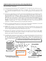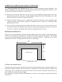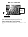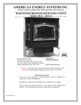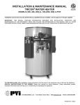
1
COUNTRYSIDE®
CORN/WOOD PELLET STOVE /FIREPLACE INSERT
Safety tested and EPA exemption tested by Warnock Hersey to UL 1482, CAN/ULC-S627, ULC-S628, APFI
requirements, Oregon administrative rules 814-23-900 to 814-23-909 and E.P.A. Method 28A.
OWNER’S MANUAL
Installation – Operation – Maintenance Instructions
PLEASE READ THIS ENTIRE MANUAL BEFORE INSTALLATION AND USE OF THIS CORN/PELLET
BURNING STOVE. FAILURE TO FOLLOW THESE INSTRUCTIONS MAY RESULT IN PROPERTY DAMAGE,
BODILY INJURY OR EVEN DEATH.
IMPORTANT: Always contact your local dealer/installer with questions before contacting the factory.
When you call have your serial number, purchase date, who installed the unit and a list of questions.
This appliance must be installed by a qualified/trained factory approved installer to assure proper operation/warranty.
9 When installing your Countryside Corn/Pellet stove, particular attention needs to be made in regards to
fire protection. If the unit is not properly installed, a house fire may result. For your safety, follow the
installation and operation instructions provided, and if a question arises contact local building or fire
officials about restrictions and installation requirements in your area.
9 Read the operations and fuel section of this manual before plugging in your unit.
9 Always unplug the unit before attempting any service work.
9 Do not connect the unit to a chimney flue already serving another appliance.
9 When installing the chimney pipe to the unit, it is important to remember that the unit operates on a
negative pressure and the chimney on a positive pressure. All chimney connections, elbows and fittings
must be airtight. (proper venting practices must be followed. Consult with a venting professional)
9 Ashes must be disposed of in a metal container with a tight fitting lid.
9 All minimum clearances to combustibles must be followed.
9 The Countryside Corn/Pellet Stove is tested for operation with 14% or less moisture corn or with wood
pellets with an ash content of no more than 3%. It is recommended that Corn with 11-12% moisture or
wood pellets with an ash content of 1% or less be used for efficient operation of this unit. Corn over
12% moisture has a lower BTU value and will be hard to burn on the lower settings.
9 It is important to use fuel that is clean, dry and consistent. Make sure that your supplier is giving you
the same fuel each time that you purchase. It is recommended that you purchase your entire heating season
supply of fuel at one time so that the fuel will be the same.
9 A voltage surge protector or ground fault outlet is required for this unit. The electrical warranty
will be voided if surge protection is not installed before operating this unit.
9 DISCLAIMER NOTICE: No guarantee is made regarding the heating capacity of this product. The actual
area that this unit will heat depends on factors such as building conditions, heat loss, type of construction,
amount and type of insulation, type of air movement and heat distribution and the location of the product.
9 IMPORTANT: Your home must be checked to verify that there is no negative pressure that will effect the
operation of this appliance.
AMERICAN ENERGY SYSTEMS, INC. GRANTS NO WARRANTY, IMPLIED OR STATED, FOR THE
INSTALLATION OR MAINTENANCE OF THE STOVE AND ASSUMES NO RESPONSIBILITY FOR ANY
CONSEQUENTIAL DAMAGE(S).
AMERICAN ENERGY SYSTEMS, INC. -150 Michigan Street SE - HUTCHINSON, MINNESOTA 55350
Web Site: www.hearthdirect.com
Rev. date 12/18/02
TABLE OF CONTENTS
PAGE
CLEAN BURN (special additive) & ESTIMATED FUEL FEED RATE CHART…………..
3-4
INTRODUCTION & SPECIFICATIONS………….………………………………………....
5
SAFETY STEPS ……………………………………………………………………………...
6
BURNING SOLID FUELS (SHELLED CORN/WOOD PELLETS)………………………...
7-8
UNPACKING YOUR COUNTRYSIDE STOVE……………………..……………………...
8
INSTALLATION REQUIREMENTS (FLOOR PROTECTION)………………..………...
9
CLEARANCES TO COMBUSTIBLES………………………………………………………
10
GUILDELINES FOR EXHAUST SYSTEMS DESIGNS……………………………………
11-12
DESIGN GUIDELINES FOR OUTSIDE COMBUSTION AIR CONNECTION…………...
13
INSTALLATION CONFIGURATIONS……………………………………………………..
14
MOBILE HOME INSTALLATION REQUIREMENTS…………………………………….
14
ALCOVE INSTALLATION REQUIREMENTS……………………………………..
15
FREESTANDING STOVE INSTALLATION CONFIGURATIONS……………………….
16-18
FIREPLACE INSERT INSTALLATION CONFIGURATIONS…………………………….
19-20
GLASS MAINTENANCE…………………………………………………………………..
21
STOVE CONTROLS………………………………………………………………………….
22
LIGHTING INSTRUCTIONS………………………………………………………………...
23
CIRCUIT BOARD FUNCTIONS…………………………………………………………….
24
SETTING THE DRAFT………………………………………………………………………
25
MAINTENANCE INSTRUCTIONS………………………………………………………..
25-27
AUTOMATIC SAFETY FEATURES………………………………………………………..
28
HOPPER AUGER SAFETY SWITCH LOCATION…………………………………………
28
THERMOSTAT INSTALLATION…………………………………………………………...
29
TROUBLE SHOOTING GUIDE……………………………………………………………..
30-32
WIRING DIAGRAM………………………………………………………………………….
33
SETTING THE CIRCUIT BOARD…………………………………………………………..
34
AIR WASH / DRAFT SLIDE GATE ADJUSTMENT……………………………………….
35-36
WARRANTY/ SERVICE RECORD…………………………………………………………
37-38
WARRANTY REGISTRATION CARD……(IN HARDWARE PACKET)
2
CLEAN BURN
CORN ADDITIVE
TM
AMERICAN ENERGY SYSTEMS INC. HAS DEVELOPED AN ADDITIVE THAT
WHEN MIXED WITH CORN VIRTUALLY ELIMINATES THE (CLINKERING) THAT
IS CAUSED BY THE COMBUSTION PROCESS OF BURNING CORN.
HOW DOES IT WORK AND WHY DO YOU NEED IT?
The clean burn additive is a unique blend of the right ingredients that will
oxygenate the combustion process producing a cleaner more productive fire. This will
generate more BTU’S out of corn, clean up the combustion process and produce less ash.
HOW DO YOU MIX THE CLEAN BURN ADDITIVE?
Depending on how much starch or protein content that you have in your corn
supply you will have to change the percentage of mixture. The normal mixture is a ratio of
one (1) part Clean Burn additive to 150 parts of corn. This translates to approximately 1/2
pound of Clean Burn for every hopper of corn. (app. 1-2 handful’s)
To mix the Clean Burn additive simply add it to the corn and mix in by hand.
If you have corn with low starch content you may be able to decrease the mixture, and corn
with high starch content will require more. The easiest way to tell if the mixture is right is,
after a day of burning, look at the Fuel Stirrer in the Firepot and if there is any buildup of
clinker on the fingers you need to increase the mixture.
If there is excessive white powder in the firepot you can decrease the mixture.
Using the Clean Burn additive will reduce maintenance, ash content, buildup in the firepot,
fly-ash on the outside of the home and will increase the heat output. The additional heat
output will more than pay for the cost of the additive.
CAN I STILL USE OYSTER SHELLS AS AN ADDITIVE?
We have found that the oyster shells, even though they will work, causes auger
jams, pre-mature wear or damage to the auger motor and excessive ash buildup. We do
not recommend that you continue to use oyster shells and if you do use them it will void
warranty on the auger system.
GIVE CLEAN BURN A TRY. YOU WILL BE PLEASANTLY SURPRISED.
CLEAN BURN
3
COUNTRYSIDE TECHNICAL DATA
ESTIMATED FUEL FEED RATE CHART
CORN: Fuel consumption will vary depending on Kernel size and moisture content
Heat Setting
Approximate fuel consumption
Test
# 1 fuel setting
18 ounces per hour
3 ounces in a 10 minute test
# 2 fuel setting
24 ounces per hour
4 ounces in a 10 minute test
# 3 fuel setting
36 ounces per hour
6 ounces in a 10 minute test
# 4 fuel setting
48 ounces per hour
8 ounces in a 10 minute test
High
72 ounces per hour
12 ounces in a 10 minute test
WOOD PELLETS: Fuel consumption will vary depending on fuel size
# 1 fuel setting
# 2 fuel setting
# 3 fuel setting
# 4 fuel setting
High
16 ounces per hour
30 ounces per hour
36 ounces per hour
48 ounces per hour
85 ounces per hour
2.5 ounces in a 10 minute test
5 ounces in a 10 minute test
6 ounces in a 10 minute test
8 ounces in a 10 minute test
14 ounces in a 10 minute test
These fuel consumption feed rates are an approximation. Each unit will vary with the type and size of
the fuel that is being burnt. The most important feed rates to check would be the # 1 setting and the
High setting to make sure that the low and high feeds are proper for the unit. If the feed rates are
drastically different contact the factory for suggestions. Do not get alarmed if the feed rates are not the
same as shown. As long as the low fire will stay lit and the high fire does not overheat the unit and
shut it down the unit is performing as it should.
The unit is designed to adapt to different size fuels and consumption circumstances.
If you are experiencing different feed rates than shown you will need to set the fuel feed rate on a lower
or higher setting to adjust for the differences in the fuel feed rate. The test weight of Corn varies from
year to year and that alone will change the heat output of the unit. There is a fine tune adjustment that
the Reseller can make to the circuit board if the low fire will not stay lit or is burning too hot. You will
need to contact your local Reseller for this adjustment.
It is recommended that when the unit is first installed in the customer’s home that the unit be fired and
run for over an hour to see if the air adjustment is right for the fuel. Making the proper air adjustment
and making sure that proper outside air has been provided will allow the unit to perform properly.
The Countryside is certified to burn shelled corn and wood pellets. The Countryside will burn other
fuels such as Cherry Pits, Barley, Oats, Wheat and other identified fuels but the feed rates and safe
operation are not warranted. Check with your local Reseller before burning fuels not approved.
NOTE: The factory will not pay warranty service calls on problems that have come up on the
unit when the proper fuel, combustion air requirements and air adjustments have not been
checked.
tdocbeff
4
DEAR VALUED COUNTRYSIDE OWNER,
We appreciate your decision to help preserve our precious environment by purchasing the Countryside
Corn/Wood Pellet Appliance. With everyone working together, we can have clean air and renewable
heat for our homes.
Please read this Owners Manual carefully before using this appliance and if you have any questions
contact your local Countryside reseller. We appreciate your business and wish you many warm days and
nights with your new Countryside Corn/Wood Pellet Appliance.
Sincerely,
Mike
Mike Haefner, President
American Energy Systems, Inc.
P.S. You are very important to the success of our business and your referral of our products is very much
appreciated. Many of our Resellers have referral rewards available and I encourage you to ask your local
dealer how to get involved in helping make our country energy self-sufficient. GOOD LUCK !
SPECIFICATIONS
American Energy Systems, Inc., manufacturer of the Countryside Corn/Wood Pellet Appliances, reserves the
right to alter its products, their specifications and/or price without notice.
Safety tested and EPA exemption tested by Warnock Hersey to UL 1482, CAN/ULC-S627, ULC-S628, APFI
requirements, Oregon administrative rules 814-23-900 to 814-23-909 and E.P.A. Method 28A.
3502 Insert
3500P&3500L
50,000 BTU/HR
50,000 BTU/HR
75 Lbs.
75 Lbs.
Width
28”
28”
Height (Insert)
23”
N/A
Height with Pedestal
N/A
33”
Depth
28”
28”
Heat Output*
Fuel Storage Capacity
CLEARANCE TO COMBUSTIBLES
Back
Vertical Termination
w/ 3” Pellet Vent
1”
Horizontal Termination
w/ 3” or 4” Pellet Vent
9”
Side
1”
1”
Corner
1”
1”
BTU output will vary, depending on the brand of fuel, size of fuel, quality of fuel and moisture content.
Consult your authorized Countryside reseller for information on the best fuel to use to get the best results.
5
SAFETY STEPS
IMPORTANT: Proper installation of this stove is crucial for proper and safe operation. Installing this
product improperly may result in a house fire and personal injury. All applicable building codes for your
location must be followed. In areas where building codes require additional steps to the installation of
this product not included in this manual, the building codes will take precedent and must be followed.
Contact your local building inspector to obtain any necessary permits or inspection guidelines before
installing the product. (This appliance must be installed by a trained professional installer to assure
proper installation and warranty of this product) Warranty Labor and shipping will not be
covered if the unit is not installed by a trained installer.
9 DISCONNECT THE POWER CORD BEFORE SERVICING THIS STOVE! A power surge
protector is required. The unit must be plugged in to a grounded 110 -volt power source.
9 Always route the power cord away from the unit. Do not route cord in foot traffic areas. Do not
pinch cord under furniture. Do not add any additional length to the power cord.
9 This product requires simple periodic maintenance for proper operation and long life of the stove.
Read and follow the maintenance schedule closely.
9 The Countryside stove is designed, approved and tested to burn shelled corn, or wood pellets.
The burning of other solid fuels such as cord wood in this stove is not permitted. If you are burning
fuels not approved for this appliance it will void the warranty and no service/warranty will be allowed.
The Countryside will burn high ash content fuels but will require additional maintenance/cleaning.
9 A working smoke detector must be installed in the same room as this product.
9 Flammable or explosive liquids such as gasoline, naphtha or engine oil must NEVER be used in or
around this stove. These liquids must be stored well away from this stove as the open flame in the
burner chamber could ignite the fumes of such liquids. Do not burn garbage in this unit.
9 According to HUD requirements, when installed in a mobile home, this stove must be grounded
directly to the steel chassis of the mobile home and bolted to the floor.
9 This stove is not intended for use in commercial installations but can be used.
9 The moving parts of this stove are propelled by high torque electric motors. The auger and Fuel
Stirrer can cause severe injury to body parts that may get near them. Keep all body parts away from
the auger and Fuel Stirrer while the stove is plugged into an electrical outlet. These moving parts may
begin moving at any time while the stove is plugged in.
9 This unit must be installed on a non-combustible surface. Make sure that the unit is level.
9 Do not attempt internal service to the unit when it is burning and or plugged into power.
IMPORTANT: It is the customer’s responsibility to make sure the Countryside appliance is
installed with the proper make up air system and the home is checked for adequate fresh air so that
the appliance does not become the fresh air source for the home.
6
BURNING SOLID FUELS (shelled corn and wood pellets)
Unlike petroleum and natural gas products, solid fuels such as corn and wood pellets create ash as the fuel
is burned. Even with the highly efficient flame your Countryside stove will produce, the solid fuels used
will produce ash. This ash will have to be cleaned out of the stove from time to time. The cleaning
procedure will be discussed later in this manual. You can minimize the amount of cleaning required and
maximize the efficiency of your stove by maintaining the correct draft settings.
The draft setting on your stove may have to be changed from time to time to accommodate your specific
burning conditions. Proper draft setting will be discussed later in this manual. The point we wish to
make here is that your Countryside stove, due to the nature of solid fuels, will require brief periodic
attention. Please do not expect to light your stove and walk away from it until you want to shut it off in
the spring. A few moments of adjustment and cleaning from time to time are an important part of burning
solid fuels.
The Countryside stove has been designed to burn shelled corn or wood pellets that meet the Association
of Pellet Fuel Industries standards. Since both of these fuels vary greatly in quality and consistency, AES
cannot be responsible for damage done to your stove due to fuel problems. The following are guidelines
to using and selecting proper fuels for your stove.
SHELLED CORN (11-12 percent moisture recommended)
9 Store your corn supply in a dry place and keep the bags or container sealed to prevent your corn from
absorbing excess moisture. Test the moisture content periodically to maintain the proper dryness.
Check your Corn for foreign objects. Your stove warranty will not cover damage done to your
stove due to foreign objects in the fuel supply.
9 Do not carry your corn supply over into the next heating season if possible unless properly
stored. If you carry over your corn supply make sure to check the corn for proper moisture content.
9 DO NOT BURN “TREATED” SEED CORN IN YOUR STOVE. Seed corn is treated with
chemical pesticides that are harmful or fatal if swallowed; therefore, seed corn is dangerous to have in
the house, especially where children can reach it. Burning treated seed corn in your stove will void
the warranty and will destroy the exhaust system on the unit.
9 Corn must be 14% or less moisture content. Wet corn will cause rapid plugging and deterioration
of the stove and exhaust system, lower the heat output and will void the product warranty.
9 Corn must be cleaned and free from debris. Corn right from the field will often have stalks, sticks,
bolts and cob debris, which can plug the auger and/or cause damage to the auger and motor. Damage
caused by dirty corn and other foreign objects are not covered by the product warranty. Ask for clean
corn when you purchase it from your local corn supplier. Clean corn can be purchased in bulk or
bagged from most elevators, feed stores or even your local farmer.
ALWAYS ASK FOR CORN WITH 11-12% MOISTURE CONTENT.
If you are having trouble finding clean Corn, contact your local Countryside Reseller and ask
them to get you an “Energy Sifter” corn cleaning system. Cleaning your corn with the Energy
Sifter from American Energy Systems will assure clean corn and a more consistent burn rate. It is
also important to vacuum out your hopper once a month to assure trouble free auguring of the corn.
7
9 There are many varieties of corn grown around the world. Each variety has unique characteristics
including the shape and size of the kernel. Your stove will burn more consistently with a small to
mid-size kernel corn. If the kernel size of the corn varies greatly or if you switch sources frequently,
you will get a less consistent burn, which will require more attention to the draft setting on your stove.
Therefore, purchasing corn from the same source will help achieve a more consistent burn. DO NOT
USE CORN WITH A HIGH WAX CONTENT!
WOOD PELLETS
9 As with corn, be consistent in your pellet supplier. Pellets will vary in content and burn
characteristics from supplier to supplier. A consistent supply of pellets will require fewer adjustments
to the draft of the stove.
9 Check your pellets for foreign objects. Your stove warranty will not cover damage done to your stove
due to foreign objects in the fuel supply.
9 Store your pellets in a dry place to prevent them from absorbing excess moisture.
9 Vacuum the hopper out after every 6-7 bags to eliminate buildup of sawdust. More often if the pellets
are poor quality. If sawdust is a problem you will have to screen each bag of fuel for a consistent
feed.
9 Wood pellets vary from supplier to supplier in ash content from less than 1% to 3% or more. Low ash
content pellets will allow you to burn the stove longer between cleanings. Only wood pellets
manufactured to the Association of Pellet Fuel Industries (A.P.F.I.) standard for residential pellet
fuels are recommended. Look for A.P.F.I. registration number on the back of pellets. Consult your
local Countryside reseller for more information on approved wood pellet fuel.
UNPACKING YOUR COUNTRYSIDE CORN/PELLET STOVE
When you receive your Countryside Corn/Pellet Stove, Leg unit or Fireplace Insert, be careful to
inspect all parts and components to make sure that nothing was damaged or lost in shipment. If there was
shipping damage, be sure to report it to your Countryside reseller, or the shipping company that delivered
your unit. Freight damage claims must be made to the Freight Company immediately. If parts are
missing contact your local Countryside reseller or contact the factory right away. Your satisfaction is
our top priority.
To uncrate your Countryside Corn/Pellet Stove:
1) Cut the banding straps and open the carton lid. The carton is stapled to the wood pallet so it will be
necessary to pull the cardboard loose from the pallet. Remove the crating box carefully lifting up over
the top of the unit. Be careful not to scratch the unit with the staples. Remove the wood blocks and
plastic. We strongly urge you to recycle the packaging materials to help protect the environment.
8
The Pedestal Ash Pan unit comes completely assembled, the Insert comes with the shroud packaged
separately and the Leg unit comes with the Legs packaged in the hopper.
The installation of the Insert Shroud is shown later in the installation manual. Make sure that the shroud is
with the unit when you get it.
The following diagram will show how to install the legs on the Leg Unit. The legs are wrapped up and
packaged in the hopper. Unpackage the legs and get the (4) nuts out of the hardware bag.
Tip the unit back so that you can get the leg onto the bolt that is sticking down in each corner of the
bottom of the base. Be sure to have someone helping hold the unit while you are attaching the leg. The
casting could break if bound or dropped. NOTE: It is best to attach the legs on one side first and then
lift the unit up level to attach the other side. You can also attach the legs on the back two corners
first and then the front.
Place the ¼” nut on the bolt that is located on the base of the unit and attach the leg to the bolt. Swing the
leg so that the foot of the leg is parallel with the 45-deg. angle of the front of the unit. Align the back leg
to match the front leg.
Be careful not to bind the leg when bolting onto the unit so that it does not break. The legs are designed
to face at a 45 degree angle so that they will face in the same direction as the slanted side of the face.
When the legs are bolted on and positioned where you like them, tighten the (4) four nuts. Make sure not
to over tighten the nuts and twist them off.
FLOOR PROTECTION
The Countryside Freestanding Stove may be installed on a combustible floor, with proper floor
protection, or on a masonry hearth. The hearth or non-combustible floor protector must extend a
minimum of (6) six inches in front of and (8) eight inches from each side of the ash removal door.
NOTE: If installing the 3502 (Insert Model) into a build-in application where there is not an existing
fireplace, you will have to install a non-combustible floor underneath and 6 inches out in front of the unit.
This would require a 2-3 inch thick masonry floor (the thickness of one brick) or ¾ inch thick rock board.
9
CLEARANCES TO COMBUSTIBLES
The stove must be installed with the following minimum clearances to side and back wall combustible
materials. NOTE: These are minimum clearances to combustible walls established by the testing lab.
The amount of room needed on the left side of the unit to access the electrical panel is (6) six inches.
When venting straight out the back of the unit, the B clearance is 1”. C clearance is for a vertical vent
install.
C
B
A
E
D
A=1” B=7” or 1”
if straight out the
wall install
C=3” if tee install
D=3”
E=1”
E
Residential/Mobile Home
Horizontal + Vertical
Corner Installation
Residential/ Mobile Home
Vertical Installation
The side and top clearance are to be used when
installing the CountrySide into an alcove as shown to
the left and below.
Top View
The 14” clearance above the back
28”
lid is only for
clearance to open
the lid. If you are using the front
lid this clearance is 1”
30”
6”
min.
HEARTH PROTECTION
10
14”
GUIDELINES FOR EXHAUST VENTING SYSTEMS DESIGN
It is recommended that only an authorized Countryside installer install your pellet/corn stove. The following installation
guidelines must be followed to ensure conformity with both the safety listing of this stove and to local building codes.
9
A listed 3” or 4” type “PL” pellet vent exhaust system must be used for FREESTANDING installation and attached to the
pipe connector provided on the back of the stove. Use a 3” to 4” adapter for 4” pipe. A cap must be used at the
termination of type “L” vent chimneys.
9
Do not terminate vent in any enclosed or semi-enclosed area, such as; carports, garage, attic, crawl space, under a sundeck
or porch, narrow walkway or closed area, or any location that can build up a concentration of fumes such as a stairwell,
covered breezeway, etc.
9
Vent surfaces can get hot enough to cause burns if touched by children. Non-combustible shielding or guards may be
required. Do not install a flue damper in the exhaust vent of this unit.
9
Termination must exhaust above air inlet elevation. It is recommended that at least 5 ft. of vertical pipe be installed
when the appliance is vented directly through a wall or in a basement. This will create some natural draft to prevent
the possibility of smoke or odor during appliance shutdown and to keep exhaust from causing a nuisance or hazard from
exposing people or shrubs to high temperatures. In any case, the safest and preferred venting method is to extend the vent
through the roof. Do not connect this unit to a chimney flue serving another appliance.
9
Distance from doors and windows, gravity or ventilation air inlet into building:
Not less that 4 ft. / 1.2 m below, 4 ft. / 1.2 m horizontally from, 1 ft. / 305 mm above (This does not apply if the
Windows are non-opening or have been fixed so they cannot open.)
9
Distance from bottom of termination and grade – 1 ft. / 305 mm minimum. This is conditional upon the plants and nature
of grade surface. The exhaust gases are not hot enough to ignite grass, plants or shrubs located in the vicinity of the
termination. The grade surface must not be a lawn. Distance from bottom of termination and public walkway is 7ft. /2.1m
minimum.
9
Distance to combustible materials – 2 ft. / 610 mm. This includes adjacent building, fences, protruding parts of the
structure, roof overhang plants and shrubs, etc.
9
It is recommended that a single or double clean-out “tee”, for cleaning the vent in both directions, be installed at every 900
junction to enable collection of fly ash and to permit periodic cleaning of the exhaust system. 900 elbows accumulate flyash and soot thereby reducing exhaust flow and performance of the stove.
9
Total length of horizontal vent must not exceed 48” (4 ft.) / 1,200 mm. All joints in the vent system must be fastened by at
least 3 screws, and all joints must be sealed with RTV silicone sealer to be airtight.
9
A 3” single-wall, stainless steel flexible or rigid exhaust pipe should be used for INSERT installations and must be
attached to the stove with a single-wall, stainless steel “tee” with a clean-out cap. The stainless steel “tee” should be
inclined at 450 to enable the vent to be centered on the stove and allow the “tee” to be cleaned without removing the stove
(see diagram on page 17).
9
When venting into an existing masonry or factory built chimney, the chimney must be cleaned, with all creosote removed.
The chimney must be a type suited for solid fuel. WARNING: The chimney and the chimney connections must be kept
clean and in good condition.
9
The “PL” vent or single wall stainless exhaust system must be installed so as to be GAS TIGHT! The vent manufacturer’s
installation procedures must be followed. In addition, pipe connections, joints and all pipe seams within the home should
be sealed with high temperature RTV silicone sealer.
9
If an insert is to be installed into an unlined masonry chimney, it is recommended that at 3” or 4” stainless steel pipe be
extended to the top of the existing chimney. The top of the existing chimney should be sealed with a steel plate (see
diagram on page 17).
11
GUIDELINES FOR EXHAUST VENTING SYSTEMS DESIGN, CONT……
To determine whether a 3” or 4” exhaust system should be used, follow the guidelines below:
1) Determine the “equivalent pipe length” for each component used according to the comparison chart
below. Add the “equivalent pipe length” of all components to get the “total equivalent pipe length”.
2) Determine the altitude at which you are installing the stove.
3) Cross-reference the “total equivalent pipe length” and the altitude using the graph below.
NOTE: The “total equivalent pipe length” should not exceed 30 feet.
Component
Equivalent Length
Horizontal Straight Pipe
Actual Length in ft. x 1.0
Horizontal Pipe
=
1 x (2+1) =
3 ft.
Vertical Straight Pipe
Actual Length in ft. x 0.5
Vertical Pipe
=
0.5 x 8 =
4 ft.
90 Elbow or Tee
5.0 feet
90 Degree Tee
=
2x5=
10 ft.
450 Elbow
3.0 feet
45 Degree Tee
=
1x3=
3 ft.
TOTAL
=
0
Equivalent Pipe Length
20 ft.
NOTE: These are guidelines only. Proper venting is accomplished by design and common sense. In most
installations 3 inch diameter venting is adequate. If it does not vent properly you will have to change it to 4”.
CRITERIA FOR SELECTING PIPE DIAMETER
MAXIMUM
25
20
4” DIAMETER ONLY
15
10
3” OR 4” DIAMETER
5
0
0
0
2
2
4
4
6
6
8
8
ALTITUDE X 1,000 FEET
12
10
10
12
12
DESIGN GUIDELINES FOR OUTSIDE COMBUSTION AIR CONNECTION
OUTSIDE MAKE-UP AIR FOR COMBUSTION IS REQUIRED ON ALL INSTALLATIONS
1) For FREESTANDING installations with horizontal through-the-wall exhaust, it is REQUIRED that
the stove combustion air intake be connected to a fresh air intake outside. If the home is newer or has
been tightly insulated it is imperative to the operation of the unit to install outside combustion air. If
you do not, then an additional 6 inch intake into the furnace room in the basement is required.
2) For INSERT installations into an existing fireplace, or FREESTANDING installations with a vertical
exhaust, outside air connection is required.
3) Connection to outside the house is REQUIRED for mobile home installations.
IMPORTANT: It is the customer’s responsibility to make sure that there is adequate fresh air to
the home so that the Countryside appliance does not become the fresh air source.
4) Only non-combustible pipe 3 inches in diameter is approved to use for outside air connections
(straight or flexible). PVC pipe is NOT approved and should NEVER be used.
5) If the air inlet is connected to the outside, it MUST be terminated with a vertical 90-degree bend
(down) or with a wind hood. Failure to do so could result in a burn back during high winds blowing
directly up the air inlet during a simultaneous power failure (see diagram above).
6) It is important not to terminate the inlet of the fresh air intake too close to the venting outlet for the
smoke. It is recommended that the inlet for the fresh air is a minimum of 3 feet away from the venting
outlet and at least 1-2 feet below.
7) Blockage, excessive length, or bends in the air intake pipe will starve the stove of combustion air. A
90-degree bend is equivalent in restriction to approximately 30 inches of straight inlet pipe.
13
INSTALLATION CONFIGURATIONS
The Countryside Corn/Pellet Stove Model J3500/3500P may be installed as follows:
1) A freestanding unit (with a pedestal only)
2) A hearth mounted fireplace insert into a masonry or factory built fireplace (3502 only)
3) A built-in heater mounted in an alcove with a pedestal
4) A built-in heater mounted on a non-combustible floor without a pedestal
MOBILE HOME INSTALLATION REQUIREMENTS
IN ADDITION TO THE STANDARD INSTALLATION INSTRUCTION, THE FOLLOWING
REQUIREMENTS ARE MANDATORY FOR INSTALLATION IN A MOBILE HOME:
WARNING
DO NOT INSTALL IN SLEEPING ROOM
1)
2)
3)
4)
5)
Stove must be permanently bolted to the floor.
Stove must have permanent outside air source.
Stove must be permanently electrically ground to the steel chassis of the mobile home.
All vertical chimney vent must have wall supports every (5) five feet.
All exhaust systems must have a spark arrestor.
CAUTION
The structural integrity of the mobile home floor, wall and ceiling must be maintained.
Check with your local building official as other codes may apply.
33”
14
ALCOVE INSTALLATION REQUIREMENTS
The Countryside is approved for the standard alcove height of 72 inches, or for a reduced alcove height
with a minimum of 14 inches from the top of the stove (clearance for opening top lids). The maximum
alcove depth is 60 inches and the listed side clearances are a minimum of 1 inch. The 14” clearance is
only needed for opening the back lid. If the front lid protrudes out of the opening a 1” clearance is all that
is required.
ALCOVE - THROUGH THE WALL INSTALLATION REQUIREMENTS
The stove is approved for horizontal exhaust; however, we recommend that the exhaust goes vertically for
five feet, or above the eave of the house. This will help draw smoke out of the stove in the event of a
power failure.
15
FREESTANDING STOVE INSTALLATION REQUIREMENTS
Horizontal Exhaust Termination:
1) Locate proper position for the type “PL” wall thimble (F). Use a saber saw or key- hole saw to cut a
2) 7 1/4-inch diameter hole through the wall (G) for a 3-inch pipe. For a 4-inch pipe, cut an 8 1/4-inch
hole. Install the wall thimble in the hole. The size of hole opening will vary with brand of wall
thimble.
3) Position stove approximately 12” from the wall on the noncombustible floor pad. Push the type “PL”
pipe (D) through the wall thimble (F). Squeeze a bead of high temperature RTV silicone sealer (A)
around the outside of the 3” diameter exhaust pipe approximately ½” from the stove back panel (B).
Firmly push on a section of type “PL” pipe (D) until the inner pipe liner pushes up against the bead of
RTV sealer. Don’t seal the entire 3” diameter pipe as you will not be able to disassemble the pipe at a
later date. The bead of silicone will act as a gasket right on the end of the 3” pipe (D). Alternate
Method: An approved type “PL” connector back clamp may be used to allow easy disconnect for
maintenance. (The RTV sealant must be used in mobile home installation)
4) Push stove with pipe attached towards wall. Pipe (D) will go through the wall thimble (F). Be careful
not to dislodge the thimble. Position stove not closer than 1” to the wall.
5) NOTE: Make sure that you leave enough clearance between the wall and the back of the unit so that
when you open the hopper lid it will not hit pictures on the back wall. It is recommended that you
leave 4-6” between the wall and the back for the unit for easy access.
6) Install type “PL” termination cap (H) with rodent screen cap (optional) on outside end of pipe. Note:
The end of the exhaust pipe must extend a minimum of 12 inches from the outside of the building.
Rodent screen cannot be less that 3/8” opening mesh.
7) If installing with combustion air from outside, cut a separate hole through the wall for the fresh air
tube (E). This tube must be 3” minimum diameter steel only. Connect outside air pipe inlet on stove
(C). This tube must be terminated with a 90 degree elbow or hood. Care must be taken not to
interfere with the operation of the combustion-air back draft damper. Always make sure that it moves
freely.
NOTE: Always check dimensions on unit before cutting hole in wall.
NOTE: air intake must be 23 feet away from the exhaust
outlet and must be 1-2 feet
lower.
16
17”
Storm Collar
Required
Locate so that exhaust
does not interfere with
fresh air
Required
17
Storm Collar
This type of installation
is not recommended in
cold climates unless
closed in and insulated.
Required
Required
WARNING: Unless the venting is enclosed and insulated this installation will cause poor venting
and serious creosote buildup in cold climate areas.
18
FIREPLACE INSERT INSTALLATION REQUIREMENTS
The Countryside Model 3502 Fireplace Insert may be installed in a masonry factory built fireplace or
on a non-combustible floor as shown below. NOTE: When installing as a fireplace insert, the unit must
extend out of the fireplace opening 12” to accommodate access to the circuit board panel, draft slide
(located on the left side of the insert) and the top front hopper lid (to fill the hopper with fuel).
CAUTION
There are serious consequences for using makeshift compromises during installation.
Always use proper listed materials. Do not cut corners. Serious complications and
possible safety risks may occur. Always use a certified installer.
NOTE: The circulation air inlet fins must be inside the room. Do not put the shroud in front of them.
NOTE: Existing fireplace dampers must be locked in the open position, seal any openings between the
masonry of the fireplace and the facing masonry.
This installation is
not recommended
19
FIREPLACE INSERT INSTALLATION CONTINUED……
The Countryside Model 3502 Fireplace Insert requires a fireplace shroud for proper installation. The
shroud is designed to slip over the stove-top between the front and back hopper lids. Shrouds can be
customized for particular installations (custom order).
1) Position unit so that the shroud can be slid over the top lid behind the sliding draft control knob
(located on the left side of the unit). Alternate Method: Open the back lid, slide shroud over sides,
slide onto front lid, close back lid, slide onto back lid.
2) Attach 3” flex pipe connector to the 3” exhaust tube on the back of the unit. Allow enough flex pipe
to pull the unit out of the fireplace opening for maintenance but be careful not to crimp pipe when
pushing insert into place.
3) You may silicone around the fireplace shroud connecting it to the stove or leave the shroud loose for
easy removal during vent cleaning. This will have to be done after pushing unit into place. Be sure to
route the stove plug-in-cord through the shroud before pushing the unit into place.
PERIODIC MAINTENANCE
At least once a year the chimney and smoke chamber must be inspected and cleaned. The fireplace insert
will have to be removed for the purpose of inspecting the fireplace insert and the chimney. The buildup
of fly-ash in the chimney pipe will cause the unit to operate inefficiently. Continued use will cause
malfunction of the unit. Venting should be checked at least monthly
42”
Standard Shroud
29”
POWER CORD ACCESS
To Remove the Fireplace Insert:
Disconnect the power supply, slide the insert forward leaving the shroud in place and being careful not to
dislodge the chimney flex pipe, open the clean-out to empty the fly-ash, inspect chimney conditions and
connections, clean as needed, slide insert back into place, make sure that all chimney connections are in
place and then re-connect the power supply.
It is important to do regular cleaning and maintenance to an insert as the venting is long and will build up
with fly-ash.
20
GLASS MAINTENANCE, ADJUSTMENT, REMOVAL AND REPLACEMENT
Your Countryside Corn/Pellet Stove comes to you with the glass door installed in place, ready for use.
The glass is surrounded on the edges with a gasket and seated in a glass channel. It is held in place with
two (2) clips on the top and two (2) clips on the bottom
REMOVAL OF BROKEN OR DAMAGED GLASS
Open the door and lift off of hinges. If the door is tight, tap gently on the bottom of the door with your
hand or rubber hammer. Lay door down on newspaper with glass clips facing you. Using a #2 Phillips
screwdriver, loosen the screws and take off the glass clips. Remove the broken glass carefully and
discard. Be careful not to loose the (2) spacer clips located in the bottom corners.
Check to make sure that the gasket material under the glass is in good shape. You can get this material
from the factory or from an authorized Countryside reseller if it needs to be replaced.
Reverse the above procedure for replacing new glass. When installing the new glass make sure that
the glass is not sitting on top of any obstruction. The glass will break when tightening the screws if
the glass is on the gasket. Hold the glass toward the top of the door glass channel when tightening.
WARNING
Do no operate unit with broken glass.
Do not substitute original factory glass.
You must use only factory authorized glass:
(811/16” x 15 1/8” high temperature Ceramic glass, 5mm thick)
Do not slam door shut.
Do not strike glass.
Do not use abrasive cleaners.
Do not clean when glass is hot.
CLEANING THE GLASS
When the fire is first started, it will produce some smoke. The smoke might accumulate on the glass
surface. Before the fire gets hot, open the door and wipe the glass surface off with a damp rag. Do not
touch the surface with your hands. If after constant use, the glass is dirty; you must clean the glass so that
it will not become etched with the fly-ash. When the glass has cooled off, take a damp rag, put a little flyash from the unit on it and clean the glass. If this does not clean the glass use a special glass cleaner
provided by your Countryside reseller. We have found that Amway crème glass & chrome cleaner
works real well.
GLASS CLIPS
Glass Spacer Clip
One each side
21
STOVE CONTROLS
Adjustable Air Deflector
Move up or down to
adjust air direction
Front view
Sliding heat exchanger tube cleaning
rod. Pull in and out to clean heat
exchanger tubes.
Adjustable Door Handle
lifts up and turns to the left
to open
Adjustable hinges. Loosen locking
nut and move in or out to adjust.
Ash Pan (3502 models only)
Ash clean outs (3500P & 3500L
model) Pull out to empty ashes
out of firebox area and back heat
exchanger area. Make sure to
push all the way in when done.
Pedestal Ash Pan (3500P & 3500L
models)
Pull out to empty ash pan. Make sure
that the ash pan is up against the seal
on the pedestal when in place.
left view
Left Side
Circuit Board control panel.
Open door and select heat and
fuel stirrer settings.
There is a scraper provided with the
unit for cleaning out the ash. There is
a hole in one end for hooking onto the
front heat exchanger tube rod for
cleaning if the unit is hot.
If you want to, you can purchase an
adhesive back hook and place it on
the back panel of the unit to store the
scraper tool. This can be purchased
at any local hardware store.
Manual Draft Adjustment
control knob. Slide in or out to
decrease or increase draft
Side view showing control operation
Adjustable Air Deflector
Slide Heat Exchanger Tube cleaning
rod in and out to clean tubes
shown pulled out
Ash Cleanouts located on the left
and right side of the front of unit.
Slide out for cleaning. (3500P &
3500L models) shown pulled out
22
LIGHTING INSTRUCTIONS
Before lighting your CountrySide for the first time make sure that all items
are out of the hopper and firebox area. Turn the heat setting and fuel stirrer
knob to the off position and push the manual draft in as far as it will go.
Note: If using a wall thermostat option, make sure that the thermostat is
turned up above room temperature. The unit will operate on low fire if the
thermostat is turned down. Always start the fire on the # 3 heat setting.
Heat Setting
Off
2
3
4
High
9 Place a small handful of wood pellets or fire starter in the firepot.
9 Squirt a small amount of fire starter gel on top of the wood pellets.
(Evenly across the wood pellets)
9 Light the fire starter and wait app. 1-minute for it to start burning.
1
Fuel Stirrer
2 3
1
Off
4
High
9 Turn the heat setting knob to the number 3 setting and pull out the
manual draft knob approximately ¼ inch. (more or less if necessary)
9 Turn the Fuel Stirrer knob to the number 1 setting and let it rotate a couple turns to stir the firestarter and wood
pellets together. Then turn the fuel stirrer off until the fire is burning good. (approximately 1 minute)
9 Once the wood pellets are burning good enough for the fuel stirrer to stay on (app. 1 minute), turn the fuel
stirrer to the number 1 setting and leave it on. Adjust the manual draft knob (located on the left side of the unit
to the left of the circuit board) so that there is approximately ½ inch of fuel in the bottom of the firepot. This
level cannot be determined quickly. Minor adjustments will have to be made until the main fuel starts coming
in and the unit is up to temperature.
9 NOTE: Even if you are burning corn or other fuels in your Countryside, wood pellets make an excellent
source of starter fuel. Corn takes too much starter gel to get lit and up to temperature.
(DO NOT START THE FIRE WITH CORN)
9 Three minutes after the heat setting knob is turned to the number 3 setting the fuel will start to feed into the
firepot. If the firepot begins to fill up with unburned fuel, open the manual draft knob a little to burn up the
excess fuel. If the fire is going out because there is too much fuel coming in, turn the heat setting knob off and
then turn back on. This will give you another 3 minutes before fuel feeds in.You can also open the hopper lid.
9 If the fire is burning too fast and the fuel is being burned up too quickly, push the manual draft knob in a little
to slow the fire down. This should be done in small 1/16” increments so that the fire doesn’t change too
quickly.
9 Once the fire has established itself (usually 10 to 15 minutes) adjust the manual draft knob so that there is
approximately ½ inch of fuel in the bottom of the firepot. Do not let the fuel build up any higher than that or
it will cause the fire to burn dirty and you will get excessive ash. If the fuel level is too low (below ¼”) the
fire may go out.
Damper Control Function
The damper control knob is located on the left side of the unit close to the circuit board access panel. You pull out
on the knob to increase the air to the firepot and push in to decrease the air to the firepot. The proper setting will
vary from home to home so fine tuning has to be done in the home with the fuel that you plan to use.
When you change fuel sources it may become necessary to readjust the damper control knob. You should not have
to continually adjust the manual knob except when using the high fuel setting. The circuit board automatically
adjusts the air to the firepot on the settings from 1 to 4.
23
CIRCUIT BOARD FUNCTIONS
Startup
When the circuit board is energized (unit plugged in) there is a 15 second purging of the auger tube to
allow fuel to enter the firepot. To initiate the Startup, turn the heat setting knob to the number 3 setting.
If the unit is started on the 1 or 2 settings the firebox temperature may not raise fast enough for the low
limit censor to engage. When the heat setting knob is turned on, the draft blower starts but the auger feed
does not start feeding fuel until after 3 minutes.
The fuel stirrer can be turned on at this time and run for a couple of turns to stir the fuel. After the fuel is
lit, the fuel stirrer can be left on the number 1 setting. Corn may require a higher setting if the moisture
content is high or if the corn has a high starch content. Wood pellets may require a higher setting if the
ash content is high or if you are running the unit on the high setting.
NOTE: Make sure that the wall thermostat is turned up so that the unit will start on the number 3 setting.
If the fire is not hot enough to engage the low limit censor, (within 20 minutes) the circuit board will
cycle through the shut down mode and the unit will shut down. The green indicator light will blink
rapidly to show that the unit is not operating properly. To restart the system, simply turn the heat-setting
knob to the off position and turn back on to the number 3 setting.
Once the unit is operating at the proper temperature (usually 10-15 minutes), select the heat setting that
you want, adjust the manual draft adjustment knob so that the fuel is app. ½ inch thick in the bottom of
the firepot. (There should be a nice bed of red coals in the bottom of the firepot).
The number 3 heat setting is best for corn and the number 4 heat setting is best for wood pellets for a high
fire burn. The high heat setting should only be used if the home is over 2500 square feet or the weather is
extremely cold. The high heat setting is intended for use with wood pellets and the highest heat setting
for corn would be the number 4 setting.
The unit is not designed to be operated for long periods of time on the highest setting. Optimum
efficiency is achieved by using lower settings. It is also recommended that the unit not be run for
extended periods of time on the number 1 setting. The draft blower and venting will fill up with fly ash
after a long period of time. Once a day pull the manual draft knob out all the way and turn the unit up on
high. Run it this way for a few minutes to clear the venting and draft blower. It is good to run the unit on
one of the higher settings at least once a week to clear the system and eliminate the buildup of fly-ash.
Shutdown
To shut the unit down simply turn the heat setting knob to the off position and the system will enter the
shut down mode. The fuel stirrer, room fan and exhaust blower will continue to operate until the low
limit safety censor tells it that the fire is out and the firepot has gone through its cleaning cycle. After this
time the fuel stirrer will shut off. When this happens the fuel auger will go into the purging cycle and
auger a small amount of fuel out of the auger into the firepot. Then the entire system shuts down.
Before starting up the Countryside Multifuel Corn/Wood Pellet unit again, it is important to remember
to shut off the fuel stirrer so that the fire can be started properly. It will also ensure that the fuel stirrer
will not start with someone having his or her hand in the firepot area.
24
SETTING THE DRAFT
A proper draft setting is crucial to the successful burning of solid fuels. Draft refers to the amount of air
flowing through the burn chamber of your stove. Too much or too little draft will cause your stove to
burn improperly and may result in the fire burning out. Please follow these guidelines carefully as you
operate your stove to achieve maximum efficiency and enjoyment.
9 The amount of draft required for your stove to burn properly will depend upon your installation and
the fuel you use. You can set your draft by looking at the flame and following these guidelines. The
manual draft knob is the rod and knob on the left side of the stove. Pulling the knob out increases the
draft and pushing the knob in decreases the draft. A little movement of the knob goes a long way to
changing the flame. It may take several trial and error adjustments on the draft to achieve the correct
setting.
9 The flame should be an “active” flame. A flame that moves around lazily and emits visible smoke
needs more draft. To give the fire more draft, pull the damper out 1/8” and check the flame again. If
the status of the flame has not changed, move the damper another 1/8” until you get a clean “dancing”
flame. If moving the damper does not change the fire, you might have negative pressure in the
home.
9 The base of the flame should be blue in color and the top of the flame should be yellow.
9 If the flame does not have enough draft, fuel will build up in the firepot and eventually smother the
flame. If this happens, or if you notice the firepot is filling up with partially burned fuel, open the
damper 1/8” at a time until the fire is clean and dancing.
9 If the flame has too much draft, the flame will look like a torch in that it will be moving rapidly and
blowing fuel out of the firepot. If you find that you have this condition, move the damper inward 1/8”
at a time until the condition of the flame changes.
MAINTENANCE INSTRUCTIONS
DAILY MAINTENANCE
9 Surfaces on the front of the stove will be extremely hot during operation. Always wear heat
resistant gloves to perform periodic maintenance.
9 Using the hole in the handle end of the clean-out tool, move the heat exchanger rod in and out 10
times and return it to operating position, all the way in. This should be performed weekly.
9 Using the clean-out tool, tap the side heat exchangers that are located on the left and right sides of the
firebox. When you open the door, they are located directly inside to the left and right. When you tap
the sides with the clean-out tool the loose fly-ash will drop out of these holes.
9 (3500P & 3500L model) Pull the lower front ash cleanouts out and scrap any fly-ash down into the
pedestal ash pan. Push them back in all the way.
25
MAINTENANCE INSTRUCTIONS CONTINUED…
9 While you are tapping the side heat exchangers, we recommend that you pull the draft knob all the
way out for a minute or two and put the unit on high fire. This will allow the unit to self-clean the
heat exchanger area, the draft fan and exhaust chimney pipe.
9 If a clinker ball develops in the firepot, scrape it out with the clean-out. You may have to do this once
or twice a day depending on the moisture content of the corn. If this is not cleaned out, it could cause
the fuel stirrer to jam. Clinker balls are a direct result of excessive corn moisture and they do not
indicate a problem with the stove. AES highly recommends an additive called “Clean Burn” be added
to your corn to eliminate these clinkers. Contact your local Countryside reseller for availability and
cost.
9 Open the stove doors and wipe the inside of the glass with a damp cloth as needed.
SPECIAL CLEANING/OPERATIONAL INSTRUCTIONS:
3500P & 3500L Models: After cleaning or when operating the model 3500P & 3500L models you need to
make sure that the clean-out plates are in the closed position. Push the front (2) clean-out slides all the
way in and make sure that you have replaced the left & right clean-out plates that are located on the inside
of the unit. (These plates are located inside the firebox to the left and right of the firepot in the lower
corners of the firebox.) If these plates are not in the closed position the unit will burn dirty.
3502 Insert Models: After cleaning or when operating the model 3502 models you need to make sure that
the clean-out plates are in the closed position. There are (2) two sets of clean-out plates that need to be
closed. The first set is to the left and right of the firepot inside the firebox. These plates need to be slid
closed after cleaning out the fly-ash. The second set of clean-out plates are located inside of the ash pan
area below the firepot. Open the ash pan, clean out all the ash, slide the plates toward the center of the
firebox to open and scrape out the ash from behind the back wall of the unit. Slide the plates closed and
replace the ash pan. Make sure to lock the ash pan in place.
All models have clean-out
plates located inside the door
in the lower left and right
corners of the firebox.
All models have a heat exchanger
tube cleaning rod to clean once a
week
3502 models have clean-out
plates located in the back right &
left corners inside the ash pan
area. Make sure that these are
closed when operating the unit.
Make sure that the ash pan is
locked in place.
3500P & 3500L models have (2)
front cleanout slides that must be
in the closed position when
burning the unit.
26
WEEKLY MAINTENANCE
9 Set the stove on high fire. Open the draft to 100% and allow the stove to burn for 15 minutes.
Resume desired heat and draft setting.
9 Shut down the stove as directed in the operating instructions. Allow the stove to cool to room
temperature. Remove the small clean-out slides in the lower corners of the firebox. Tap the sides of
the burn chamber with the clean-out tool. Do not tap the firewall behind the burn box as it may
damage the insulation. Using the clean-out tool, scrape the fly ash from the clean-out chambers
toward the front of the burn chamber. Remove the fly ash from the burn chamber and replace the
clean out chamber doors.
9 Remove the ash pan and dump the ash into a metal container.
9 Remove the firepot by stopping the fuel stirrer in the upright position, slide the collar off of the fuel
stirrer coupler shaft and pull up and out on the firepot. Using the clean-out tool, remove any ash that
might have built up in the system or air intake.
9 Cleaning of the exhaust system will depend upon the ash and debris content of your fuel. If your fuel
has a high ash content and/or significant debris in it, your exhaust system will require weekly
cleaning. Cleaner fuels will allow for monthly cleaning of the exhaust system. Remove the exhaust
pipe from the back of your stove and remove any ash that my have collected in the pipes. Replace the
pipes to the stove and seal with high temperature seal tape. If you have installed proper clean out tees
you will not have to take the chimney sections apart.
9 While you are doing your weekly cleaning, have the unit set on high and the draft knob all the way
out. Remember the unit is not burning. After cleaning, push the draft knob back into the stop collar.
REMEMBER: A clean unit burns efficiently and will remain trouble free!
SPRING CLEANING:
When the heating season is over make sure that you clean out all of the fuel in the hopper, firebox area,
ash pan and firepot area Corn can accumulate moisture over the summer months causing the unit to rust
and the fuel to mold.
It is recommended that prior to shutting down the unit in the spring, run the unit on the higher settings for
a day to help clean out the heat exchanger system, venting system and firebox area.
When the unit is cleaned out, take the venting apart, clean out the fly-ash, rinse the venting out with a
water hose and let dry, take the draft blower off and clean, clean out all areas such as back heat exchanger
and lubricate the auger, auger tube, firepot area, fuel stirrer shaft and bearings and hopper area with a light
oil. (something like Pam cooking oil works great to coat the inside of the unit and the moving parts.
Clean the glass, doors and outer cabinet so that you are ready for the next heating season.
27
AUTOMATIC SAFETY FEATURES
WARNING
These automatic safety features must not be bypassed.
9 Power Outage
During a power outage, the stove will shut down safely. It will not automatically restart when the
power returns, unless the exhaust is still up to temperature (see “Lighting Instructions” page 21).
9 Overheating
A high temperature switch will automatically shut down the stove if it overheats. The stove will need
to be manually re-lit. Allow 45 minutes before re-lighting.
9 Auger Cut-Off
When the back hopper lid is opened the fuel auger stops. It will resume operation when the lid is
closed. The hopper lids must be kept closed for proper operation. If the lid is left open the fire will
go out. If fuel gets lodged in the back hinge area of the hopper, when you close the lid, the switch
might not work. Always make sure that the sealing surface is clear of fuel before closing the lid.
HOPPER AUGER SAFETY SWITCH LOCATION
The hopper auger safety switch is mounted in the back of the hopper, up next to the back lid. The
assembly is enclosed to keep the fuel from entering the switch locale. When the lid is opened it cuts
power to the auger motor. Power is resumed when the lid is closed. If the lid is left open for more than a
couple of minutes the fire will go out. Always have the fuel ready to load into the hopper before opening.
28
THERMOSTAT INSTALLATION
9 The Countryside can be installed with and operated by a wall-mounted thermostat. However, a wall
thermostat is not provided with the stove. A wall thermostat can be purchased from your reseller or at
most home improvement centers or hardware stores. The wall thermostat needs to be for a low
voltage system. Most thermostats will have instructions with them as to where to place them in your
room. Please follow the thermostat manufacturer’s instructions carefully.
9 There are two (2) male spade terminals on the back of the control panel near the center. Connect the
two wires from the wall thermostat, one to each of these spade terminals. Needed: 2 female ¼”
insulated terminals.
9 Make sure that the wires are routed to protect them from hot surfaces. Do not cross wires with
circuitry on board.
9 The circuit board is located on the left side of the unit. Remove the ¼” hex head screw and pull
circuit board towards you. Lift the circuit board out of the housing. Do not crimp or stretch the wires
leading from circuit board pigtail. (Unplug the power cord before working on unit)
9 Reinstall in reverse procedure.
Back of circuit board
Two (2) ¼” male spade
connectors, one for each
wire from wall thermostat
It is a good idea to use the thermostat option to achieve uniform control over your heating needs. By
setting the unit on a number 3 setting (this is the normal setting but can be any setting from 2-high) for
high fire and letting the wall thermostat control it, the fire will drop down into a pilot fire after the home
reaches the desired temperature.
If you are gone and the home requires heat, the unit will automatically resume the high setting when the
thermostat calls for heat.
29
TROUBLE SHOOTING GUIDE
Unplug stove before performing any maintenance work. Do not work on unit when it is hot.
PROBLEM
? Fire burns with a lazy, orange flame
and/or fuel builds up in the grate and the
window gets sooted up.
CAUSES
♦
Insufficient combustion air.
♦
Feed rate too high.
♦
Corn or wood pellets have too
much moisture – need 14% or less;
10%-12% is ideal.
♦
Combustion/Exhaust blower
plugged or going out.
♦
Venting plugged with fly ash or ice.
♦
House does not have adequate
make up air (negative pressure)
SOLUTIONS
9
Remove any clinkers or ash from
the firepot by using scraping tool.
Shake ashes into ash pan.
9
Clean out primary air in firepot
holes if plugged.
9
Empty ash drawer and clean out
back heat exchanger by removing
the lower access plates.
9
Tap the side exhaust heat
exchangers to clean them as shown
on page 23 & 24.
9
Change to a better grade of fuel if
necessary. See page 5-6 regarding
fuel quality.
9
Check that damper control knob is
adjusted properly.
Pull out to
increase fire burn.
9
Check gasket seal around the door.
If the door is loose, adjust the
handle latch. A small adjustment
can be made to the door seal by
adjusting the door latch rod and /or
the door hinges. Replace the door
gasket if necessary.
9
Check for blockage in the air inlet
tube or exhaust pipe. Clean out as
necessary.
9
Check combustion exhaust blower
impeller. This can be done by
removing the exhaust pipe and
shining a light into the tube.
9
Replace combustion exhaust blower
if necessary.
♦
NOTE: Negative pressure in a home is
a serious issue.
All Countryside
appliances should be installed with
outside air hookups
Also make sure that adequate ventilation
is supplied for the rest of the home or
the unit will become the air intake
causing problems.
30
PROBLEM
? Fire goes out or stove shuts down
automatically.
? Fuel will not feed.
CAUSES
♦
Hopper is empty.
9
Refill hopper.
♦
Fuel is not feeding.
9
See “Pellets will not feed” below.
♦
High limit temperature switch has
tripped.
9
Allow stove to cool for 1 hour and
relight. If the stove has been
operating at a medium to high burn
and the convection fan has been
turned down low, then the fan
should be turned up higher. If this
problem persists, particularly at
lower burn rates, then the high limit
snap switch should be replaced by
your
authorized
Countryside
reseller.
♦
Combustion air too high.
9
Adjust the damper
combustion airflow.
♦
Fuel feed rate is too low.
9
Have your Countryside reseller
adjust the fuel control.
♦
♦
Hopper is empty.
Auger, circuit board, high limit
switch tripped
Foreign object caught in auger
Fuel is dirty or wet
Auger, circuit board, pressure
switch or relay.
9
Check contents of the hopper. Add
fuel if necessary.
Check all operation, fuses
Clean out auger system
Have your Countryside reseller
diagnose the problem and replace
the parts.
Exhaust gas is not up to
temperature. Started on too low of
Setting. Must be # 3
Low limit snap switch not operating
correctly; may be defective.
9
Relight the stove.
Start on # 3 setting
9
Have your Countryside reseller
replace the low limit switch.
♦
Wires to either the low limit snap
switch (mounted on the side of the
firebox) are loose or disconnected.
9
Contact your Countryside reseller
for service.
♦
Low limit snap switch has failed in
the closed position.
9
Have your Countryside reseller
replace the low limit snap switch.
♦
Unit has not cooled down yet.
9
It can take up to 1 hour for the unit
to cool down enough for the blower
to shut off. If it takes longer than 2
hours for the blower to shut off or if
it fails to shut off contact your local
Countryside service technician.
♦
♦
♦
? Stove runs for 30 minutes and then
shuts down.
♦
♦
? Blower will not shut off after the fuel
has been switched off and the stove has
cooled down.
SOLUTIONS
31
9
9
9
to
reduce
PROBLEM
? Blower will not operate.
? Soot or fly ash in the house.
CAUSES
♦
No power to stove.
SOLUTIONS
9
Check to see that the stove is
plugged into the wall outlet.
9
Check to see if your circuit breaker
has “tripped”.
♦
No power to control board.
9 Check wire connection between
the high limit snap switch and
the terminal block (see page 30).
♦
Cleaning the window, particularly
when the stove is operating.
Leakage on the joints between the
combustion fan, exhaust pipe and
“PL” vent. This will be evidenced
by dust on the impeller of the
convection fan and in the heat
exchanger tubes.
Using a conventional vacuum for
cleaning. Ash will bypass and enter
the room.
Negative pressure in home sucking
ash/soot out of venting and unit
9
Clean the glass when the unit is not
running
9
Seal any leaks in the exhaust
system with RTV high temperature
silicone sealer.
9
Use approved ash Vacumm
9
Correct negative pressure situation
9
Pull the insert away from the
fireplace opening.
Thoroughly
clean the opening and paint the
inside of the opening with latex or
an inexpensive spray paint to hold
the finer particles of dust.
♦
♦
♦
♦
Fireplace insert installation: If the
existing fireplace opening was not
thoroughly cleaned and painted
before the insert was installed, then
the convection fan may be picking
up the fireplace dust, soot or ash
and blowing it into the house.
? Buildup of soot on glass, venting and
heat exchangers
♦
♦
♦
♦
♦
Dirty fuel
Wet Corn (above 15% moisture)
Inadequate air supply
Negative pressure in home
Air wash plugged or out of
adjustment
Fuel stirrer keeps jamming/
breaking
Buildup in firepot, dirty wet fuel, poor
quality fuel, negative pressure in home
Make sure you have clean fuel
Dry the corn down to 11-12%
moisture if possible or mix with
wood pellets
9 Pull manual draft control out
slightly to make sure that there is
app. ½ inch of fuel in firepot
9 Install outside air to unit and make
sure that the home has adequate
make-up air. (suggested 6” makeup air into basement)
9 Clean air-wash bracket located on
bottom of glass door
9 Adjust glass so that there is a 1/16th
gap in the bottom
Add clean burn additive
Use clean, dry approved fuel
Correct negative pressure situation
9
9
CAUTION: When performing any internal electrical maintenance
• Moving parts inside of the cabinet may cause injury. Do not operate unit with panels removed or open.
• HOT parts. Do not operate the unit with panel open.
• Risk of electrical shock. Disconnect power before servicing unit.
• In the event of component failure, replace with original factory equipment.
IMPORTANT: Electrical work must be performed by an authorized technician.
32
PROBLEM
Fuel burns off to quickly, have difficulty
keeping a pilot fire.
CAUSES
Air shutter is open to far.
Over drafting on a vertical install.
Outside air is not hooked up
Positive or negative pressure in home is
affecting the units operation
Foreign object caught in the auger and
will not turn.
Accidental object in fuel.
Getting to much ash.
Dirty fuel
SOLUTIONS
Adjust your air shutter to a more closed
position.
A chimney restrictor may need to be
installed. Consult with your Countryside
dealer.
Make sure that the installation is correct
and nothing is affecting the furnace room
If there still is a fire, let it extinguish and
let furnace cool down. Unplug unit after
the fire has exhausted. It will be necessary
to clean out hopper. As you are facing the
furnace open the right hand side panel. The
auger motor will have a small cooling fan
on the back. Turn the fan counter
clockwise until tension is off the auger.
Open the front door of the unit and pull the
auger out. Prying on the auger without
loosening first can damage auger gear box.
Adequately screen corn. Dirty , wet fuel
will produce excessive ash
Wet fuel
Lack of clean combustion air.
Dirty or plugged stove or venting. Poor
exhaust vent configuration.
Take proper steps to check corn for proper
moisture and to adequately protect from
the elements to not take on moisture.
Check damper control and check
combustion air inlet for obstructions.
Negative pressure present in the home
Combustion motor going out.
Check all cleanouts and exhaust venting
for obstructions. Refer to cleaning section
of this manual.
Use combustion enhancement system
Call your Countryside reseller to inspect
installation and operation. Replace any
bad parts.
On higher heat settings combustion
enhancement system will keep ash
volume down.
The heat output is not as high as when
the furnace was installed.
Wet or dirty fuel.
Inadequate cleaning.
Dirty room air filter.
Wet fuel has a much lower BTU output.
The furnace requires 14% or lower
moisture corn. Dirty fuel does not produce
adequate heat. Excessive amounts of fines
interrupt the amount of corn delivered for
burning and will decrease heat output.
Change of fuel to lower BTU value
Negative pressure or improper ductwork
is causing unit to perform improperly
Clean heat exchangers daily, tap side
exchangers, inspect furnace for air flow.
Clean or replace filter.
Have dealer check for proper installation
and negative pressure in home.
WARNING: This section is only for qualified technicians.
33
Countryside Wiring Diagram (Ortech Circuit Board)
Neutral wire
MF3537 low
temperature
normally open
110 deg. snap
disk
thermostat
White from
power cord
MF3540 Fuel Stirrer
gear motor (connect to
brown wire on harness)
White wire
from wire
harness
When this thermostat disk
malfunctions it will either
shut down all stove
operations (stuck open) or
The unit will continue
operating without any fire
(stuck closed)
Black from
power cord
MF3542 Exhaust
draft Motor (connect
one wire to red wire
and one to black
wire on harness)
Ground wire
MF3537 normally
open 110 deg.
room fan snap disk
thermostat
When this thermostat disk
malfunctions it will either
shut down the room fan
(sticks open) or the room
fan will continue to run
even after the stove is
cool)
MF3573 (6Z906)
auger fuel feed gear
motor
Green
wire
Orange
wire
Gray
wire
white
wire
NO
wire
Purple
wire
Blue
wire
Black
wire
Red
wire
Brown
wire
MF3536 Hopper Lid
safety switch
When the hopper lid is open
the auger motor will stop
MF3538 normally
closed 250 deg.
High limit snap
disk thermostat
Molex connector
plugs into back
of circuit board
When this snap disk
thermostat malfunctions it will
stop the fuel feed auger (sticks
open) If the room fan
malfunctions this disk will
open and shut off the fuel feed
auger
34
MF3541 Room Fan
(circulated room air)
SETTING THE CIRCUIT BOARD
If the low fire heat setting is too low for the fuel that
you are burning and the fire goes out, the number 1 or
2 heat setting can be adjusted through the access hole
located next to the system indicator light. (2)
If the draft setting is too low on the number 1 or 2-heat
setting, it can be adjusted through the access hole
located next to the fuel stirrer knob. (1)
Heat Setting
2
1
3
Off
4
To adjust the settings, place a small screwdriver
through the hole to the adjustment screws. Turning the
screw
clockwise
increases
the
draft
and
counterclockwise decreases the draft. (1) Turning the
screw clockwise decreases the fuel feed rate and
counterclockwise increases the fuel feed rate. (2)
The systems indicator light will blink showing the
number that you are on. There are 10 settings that are
available with 1 blink being the lowest and 10 blinks
being the highest. When you turn the adjustment
screw to the next setting the light will blink the number
that you are on and then the light will stay on.
(Example: If the setting is turned to # 9 the light will
blink 9 times and then stay on).
Note: Number 1 on the draft adjustment setting is the
lowest setting and on the Fuel Feed rate adjustment
setting it is the highest feed rate. As you turn the
adjustment screw clockwise 1 – 2 – 3, etc the draft (1)
will increase and the fuel feed rate (2) will decrease.
The normal settings on both should be 1 blinks
THESE SETTINGS NEED TO BE MADE
BY A QUALIFIED COUNTRYSIDE
SERVICE TECHNICIAN.
The circuit board fuse is located on the back of the
board. If the board does not work, check the fuse to
make sure that it is good.
The thermostat hookup is located on the back of the
circuit board. See thermostat installation.
35
High
Draft
Adjustment
Fuel Stirrer
1
Off
2
3
4
High
Fuel Feed Rate
Adjustment
System Indicator
Light
NEW AIR WASH SYSTEM FOR COUNTRYSIDE UNITS
NOTE: These adjustments should only be made by a qualified technician
B
A
The new air wash system is an integral part of the firepot system. This will enable the unit to perform better under negative air
pressure situations in the home. The Air Wash Bracket (B) needs to be adjusted to within 1/16”- 1/8” away from the glass
surface. To do this you must loosen the two (2) ¼” nuts (A) and slide the bracket in the direction that is needed. Be sure to
tighten the nuts securely but not too tight to that they break.
NOTE: If you adjust the Air Wash Bracket too close to the glass you will not get adequate air wash and you could break the
glass. Do not close the door fast. Check to make sure the bracket clears the glass
¼” nuts, slide to outside to close,
slide to inside to open
If you take the Firepot out of the Firepot Cradle you will see two (2) ¼” nuts located toward the bottom front side of the firepot
cradle. If you want to reduce the amount of air that is directed to the air wash and re-direct it into the firepot you need to
loosen the nuts and slide the nuts toward the outer sides of the firepot cradle. Be careful not to close them too much or it will
make the glass dirty and the fire might go out on the lower heat settings. It is best to leave the plates wide open as they are
shipped from the factory. Be careful not to over tighten the nuts and twist them off. They cannot be replaced.
36
DRAFT SLIDE GATE ADJUSTMENT
Exhaust Draft Motor
located inside of Left
side panel
NOTE: Always
disconnect power
before making this
adjustment.
Draft Slide
Gate
# 10 bolt with 5/16 hex head
The normal operation of the Countryside would be with the Draft Slide Gate open fully as shown. When
the gate is in the fully open position, the plate will be against the mounting plate as shown.
If the unit needs a draft correction adjustment, the bolts are loosened and the slide gate is rotated a few
degrees at a time until the proper operation of the unit is achieved.
NOTE: This adjustment must be made by a qualified Countryside installer
When rotating the slide gate, be careful not to damage the gasket. Re-tighten the bolts and check for
leakes.
37
5 YEAR LIMITED WARRANTY
This warranty is issued by American Energy Systems, Inc. (Manufacturer) and extends only to the original purchaser of
this product.
This limited warranty will not become effective unless you have returned the attached warranty card within 30 days of
your purchase. If you fail to do so, you may make no claim under this warranty. American Energy Systems, Inc.
excludes and disclaims all implied warranties including, but not limited to, the implied warranty of merchantability.
For a period of (five) 5 years from the original purchase, Manufacturer will warrant, to the original consumerpurchaser, that all steel components are free from defects in materials and workmanship (except the firepot, which is
covered by a one- (1) year warranty and glass which carries a lifetime warranty against heat breakage). There is
expressly no warranty on the fiberglass rope gasketing, pyroboard insulation (brick backing), log sets, fuel stirrer, paint,
brass or gold plated surfaces, baffles or handles.
The original manufacturer covers all electrical components, for a period of one year from the original purchase date.
The warranty covers defects in materials and workmanship in covered components, provided the product has been
installed and operated strictly in accordance with manufacturers printed instructions. This warranty does not cover
damage or breakage due or caused by mishandling, freight damage or misuse or unauthorized modification of the
structure or electrical system.
This warranty will become null and void if unit is self-installed or not installed by an authorized installer.
This warranty will become null and void if unauthorized fuel is used. Seed Corn and Wax Corn is prohibited.
Before exercising this warranty, a local representative must inspect the unit to determine if the unit is defective. If the
inspection reveals that the failure is due to defective material or workmanship and the part is covered by the condition of
this warranty, the Manufacturer will, at its option, repair or replace the defective part. The sole duty of the
Manufacturer and liability under this warranty is limited to the repair or replacement of the covered defective part. The
purchaser shall assume all costs related to shipping the replacement parts or return of the unit to the factory for
replacement. If it is determined that the defect was caused by the Manufacturer, the Manufacturer will cover the costs
of shipping the repaired unit or replacement parts to the original purchaser.
REMOVAL OR REINSTALLATION COSTS ARE NOT COVERED BY THIS WARRANTY.
Neither the Manufacturer, nor the Reseller to the purchaser, accepts responsibility, legal or otherwise, for incidental or
consequential damage to property of persons resulting from the use of this product. Any warranty implied by law,
including but not limited to implied warranties of merchantability or fitness, shall be limited to one year from the date of
original purchase. Whether a claim is made against the Manufacturer based on a breach of this warranty or any other
type of warranty, expressed or implied by law, Manufacturer shall in no event be liable for any special, indirect,
consequential or other damages of any nature whatsoever in excess of the original purchase price of this product. All
warranties by Manufacturer are set forth herein and no claim shall be made against Manufacturer on any oral warranty
or representation.
THE MANUFACTURER WILL NOT B LIABLE FOR ANY DAMAGE RESULTING FROM THIS
APPLIANCE BEING INSTALLED BY A NON-CERTIFIED/FACTORY TRAINED INSTALLER
Some states do not allow the exclusion or limitation of consequential damages, or limitations of implied warranties, so
the limitations or exclusions set forth in this warranty may not apply to you. This warranty gives you specific legal
rights and you may also have other rights, which vary, from state to state.
Warranty/replacement parts must be handled through the dealer that sold you your appliance.
ALL CLAIMS NOT HANDLED THROUGH YOUR LOCAL DEALER UNDER THIS WARRANTY MUST BE
MADE IN WRITING TO THE MANUFACTURER AT:
AMERICAN ENERGY SYSTEMS, INC., 150 Michigan Street SE, Hutchinson, Minnesota 55350
Technical Support telephone number 320-234-0743
Included with the claim needs to be the following:
Name, address and telephone number of local reseller or representative.
Name, address and telephone number of the original purchaser.
Date of purchase along with the model and serial number of the unit.
Nature of defect and procedures of what has been done to correct the problem. (unit must be checked out by the
dealer that sold you the unit before submitting warranty replacement parts.)
38
SERVICE RECORD
DATE
SERVICE OR CLEANING PERFORMED
This record must be sent in when any warranty claims are made.
39