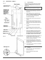
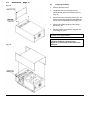
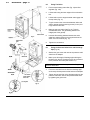
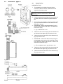
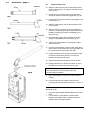
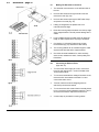
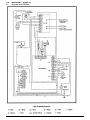
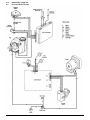
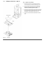
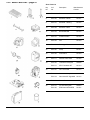
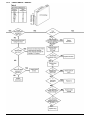
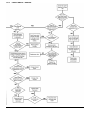
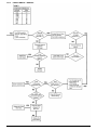
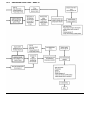
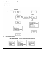
1
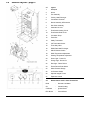
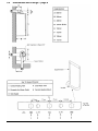
Baxi Bahama 100
Gas Fired Wall Mounted Combination Boiler
Installation and
Servicing Instructions
BAXI
Page 2
Natural Gas
Baxi Bahama 100
G.C.Nº 47 075 02
Baxi Limited is one of the leading manufacturers of domestic
heating products in the UK.
Our first priority is to give a high quality service to our
customers. Quality is designed into every Baxi product products which fulfil the demands and needs of customers,
offering choice, efficiency and reliability.
To keep ahead of changing trends, we have made a
commitment to develop new ideas using the latest
technology - with the aim of continuing to make the products
that customers want to buy.
Baxi is also the largest manufacturing partnership in the
country. Everyone who works at the company has a
commitment to quality because, as shareholders, we know
that satisfied customers mean continued success.
We hope you get a satisfactory service from Baxi. If not,
please let us know.
Baxi is a BS-EN ISO 9001
Accredited Company
The boiler meets the requirements of Statutory Instrument
“The Boiler (Efficiency) Regulations 1993 Nº 3083” and is
deemed to meet the requirements of Directive 92/42/EEC on
the energy efficiency requirements for new hot water boilers
fired with liquid or gaseous fuels:Type test for purpose of Regulation 5 certified by:
Notified Body 0086.
Product/Production certified by:
Notified Body 0086.
For GB/IE only.
Contents – page 3
Section
Page
1.0
Introduction
4
2.0
General Layout
5
3.0
Appliance Operation
6
4.0
Technical Data
7
5.0
Dimensions and Fixings
8
6.0
System Details
9
7.0
Site Requirements
12
8.0
installation
17
9.0
Electrical
24
10.0
Commissioning the Boiler
26
11.0
Fitting the Outer Case
28
12.0
Servicing the Boiler
30
13.0
Changing Components
28
14.0
Short Parts List
41
15.0
Fault Finding
42
16.0
Operational Flow Chart
46
17.0
Ignition Flow Chart
48
18.0
Notes
49
1.0
Introduction – page 4
Fig. 1
NOTE: This appliance must be installed in accordance with the
manufacturer’s instructions and the regulations in force.
Read the instructions fully before installing or using the appliance.
Fig. 2
“Benchmark” Log Book
As part of the industry-wide “Benchmark” initiative
all Baxi boilers now include an Installation,
Commissioning and Service Record Log Book.
Please read the Log Book carefully and complete
all sections relevant to the appliance and
installation. These include sections on the type of
controls employed, flushing the system, burner
operating pressure etc. The details of the Log
Book will be required in the event of any warranty
work. Also, there is a section to be completed at
each subsequent regular service visit.
1.1
Description
1. The Baxi Bahama 100 is a fully automatic gas fired wall
mounted combination boiler. It is room sealed and fan assisted,
and will serve central heating and mains fed domestic hot
water.
2. The boiler is preset to give a maximum output of 29.3 kW
(100,000 Btu/h) for hot water. The central heating is factory set
to 80,000 Btu/h, but can be rated as required from 50,000 to
100,000 Btu/h.
3. It is designed for use on Natural Gas (G20) and can be
converted to use Propane.
4. The boiler is suitable for use only on fully pumped sealed
heating systems. Priority is given to domestic hot water.
5. A label giving details of the model, serial number and Gas
Council number is situated on the rear of the outer case lower
door panel (Fig. 1).
6. The boiler data badge is positioned on the back face of the
facia box (Fig. 2).
7. The boiler is intended to be installed in residential / commercial
/ light industrial E.M.C. environments on a governed meter
supply only.
8. The boiler must be installed with one of the purpose designed
flues such as the standard horizontal flue kit, part nº 241028.
9. All systems must be thoroughly flushed and treated with
inhibitor (see section 6.2).
1.2
Installation
1. The appliance is suitable for installation only in G.B. and I.E.
and should be installed in accordance with the rules in force.
For Ireland install in accordance with l.S.813 “INSTALLATION
OF GAS APPLIANCES”. The installation must be carried out
by a CORGI Registered Installer or other competent person
and be in accordance with the relevant requirements of GAS
SAFETY (Installation and Use) REGULATIONS, the
BUILDING REGULATIONS (Scotland) (Consolidation), the
LOCAL BUILDING REGULATIONS, the CURRENT I.E.E.
WIRING REGULATIONS and the bye laws of the Local Water
Undertaking. Where no specific instructions are given,
reference should be made to the relevant BRITISH
STANDARD CODES OF PRACTICE.
1.3
Optional Extras
KIT
PART Nº
HORIZONTAL FLUE KITS
Flue Extension 0.25M
241102
Flue Extension 0.5M
241101
Flue Extension 1M (Use two kits for 2M etc.)
241100
Flue Bend – 45º (Reduce overall length of
flue by 0.5m when fitting this bend)
241104
Flue Bend – 90º (Reduce overall length of
flue by 1m when fitting this bend)
241103
Wall Liner/Internal Fixing
236441
VERTICAL FLUE KITS
Flue - 125/80mm Dia Concentric
Twin Flue - 80mm Dia
CONTROL ACCESSORIES
Programmable Room Thermostat (24 hour)
Programmable Room Thermostat (7 day)
Integral Electronic Timer Kit (7 day)
Integral Electro-Mechanical Timer Kit
(12 hour am/pm)
FUEL KIT
LPG Conversion - Propane
241107
241123
236254
238326
241550
241087
245620
2.0
General Layout – page 5
2.1
Layout
1.
Backplate
2.
Airbox
3.
Fan Assembly
4.
Primary Heat Exchanger
5.
Combustion Chamber
6.
Burner Assembly & Electrodes
7.
Gas Valve Assembly
8.
Automatic Air Vent
9.
Flow Switch Heating Circuit
10.
Flow Switch DHW Circuit
11.
Circulation Pump
12.
Facia Box
13.
Safety Thermostat
14.
CH Thermostat Sensor
15.
Three Way Valve
16.
DHW Plate Heat Exchanger
17.
ON-Off Selector Switch
18.
DHW Temperature Adjustment
19.
Heating Temperature Adjustment
20.
Green Light - Power On
21.
Orange Light - Burner On
22.
Red Light - Flame Failure
23.
Flame Failure Reset Switch
24.
Water Pressure Gauge
25.
Air Pressure Switch
26.
Optional Integral Timers
27.
Expansion Vessel
2.2
Nomenclature used in these instructions
DHW
-
Domestic Hot Water
CH
-
Central Heating
CVI Board
-
Ignition Board
ECS Board
-
Control Board
3.0
Appliance Operation – page 6
NOTE: All delay timers mentioned in 3.1 and 3.2 are
overridden by domestic hot water demand.
3.1
Central Heating Mode
1.
With a demand for heating, the pump circulates water
through the primary circuit. At a flow rate of
approximately 125 I/hr the central heating flow switch
operates, initiating the ignition sequence.
2.
The main burner ignites at low rate, then the gas valve
controls the gas rate to maintain the heating
temperature measured by the thermostat sensor.
3.
When the flow temperature exceeds the setting
temperature, a 3 minute delay occurs before the burner
relights automatically (anti-cycling). The pump
continues to run during this period.
4.
When the demand is satisfied the burner is
extinguished and the pump continues to run for a
period of 30 seconds (Pump Overrun).
3.2
Domestic Hot Water Mode
1.
Priority is given to the domestic hot water supply. A
demand at a tap or shower will override any central
heating requirement.
2.
The flow of water will operate the DHW flow switch
which requests the 3 way valve to change position. This
will allow the pump to circulate the primary water
through the DHW plate heat exchanger.
3.
The burner will light automatically and the temperature
of the domestic hot water is controlled by the
thermostat sensor.
4.
When the domestic hot water demand ceases the
burner will extinguish and the diverter valve will remain
in the domestic hot water mode, unless there is a
demand for central heating.
3.3
1.
3.4
1.
Frost Protection Mode
The frost protection mode is integral to the appliance
when left in the domestic hot water and central heating
position. If the system temperature falls below 5º C then
the boiler will fire on its minimum setting until a flow
temperature of 30º C is reached. Further protection can
be incorporated by using a system frost thermostat.
Pump Protection
The control system continually monitors the time since
the pump last operates. This will result in the pump
being run for 10 seconds every so often to prevent
seizure.
4.0
Technical Data – page 7
5.0
Dimensions and Fixings – page 8
6.0
System Details – page 9
6.1
Information
1.
The Baxi Bahama 100 Combination Boiler is a ‘Water Byelaws Scheme - Approved Product’. To comply with the Water
Byelaws your attention is drawn to the following installation requirements and notes (IRN).
a) IRN 001 See text of entry for installation requirements and notes.
b) IRN 116 Byelaw 90 and 9l.
c) IRN 302 Byelaw 14.
2.
Reference to the WRC publications, ‘Water fittings and materials directory’ and ‘Water supply byelaws guide’ give full
details of byelaws and the IRNs.
6.2
1.
Central Heating Circuit
The appliance is suitable for fully pumped SEALED SYSTEMS ONLY.
Treatment of Water Circulating Systems
•
All recirculatory water systems will be subject to corrosion unless an appropriate water treatment is applied. This means
that the efficiency of the system will deteriorate as corrosion sludge accumulates within the system, risking damage to
pump and valves, boiler noise and circulation problems.
•
For optimum performance after installation this boiler and its associated central heating system must be flushed in
accordance with the guidelines given in BS 7593:1992 “Treatment of water in domestic hot water central heating
systems”.
•
This must involve the use of a proprietary cleanser, such as BetzDearborn Sentinel X300 or X400, or Fernox Superfloc.
Full instructions are supplied with the products, but for immediate information please contact BetzDearborn (0151 420
9563) or Fernox (01799 550 811) directly.
•
For long term protection against corrosion and scale, after flushing it is recommended that an inhibitor such as
BetzDearborn Sentinel X100, or Fernox MB-1 or Copal is dosed in accordance with the guidelines given in BS
7593:1992.
Failure to flush and add inhibitor to the system may invalidate the appliance warranty.
•
•
6.3
1.
6.4
It is important to check the inhibitor concentration after installation, system modification and at every service in
accordance with the manufacturer’s instructions. (Test kits are available from inhibitor stockists.)
For information or advice regarding any of the above contact the Baxi Helpline.
Bypass
The boiler has an integral pre-set bypass and in most cases this should suffice. However in certain circumstances, e.g.
on systems where there is a high resistance and TRV’s are fitted to all the radiators it may be necessary to fit an
external by-pass. This should be of the automatic type and not a gate valve or ball type valve. The valve must be fitted
between the heating flow and return to the boiler before any other part of the system, i.e. Radiators, Diverter valves etc.
If there are any doubts, contact the technical help line. (see page 7 for flow rates).
System Control
1.
The boiler is designed for use in a heating system that incorporates external controls, i.e. a minimum of a timer device.
2.
Suitable timer kits are available as optional extras.
3.
For optimum operating conditions and maximum economy the fitting of a programmable thermostat, such as one of the
Baxi Bahama 100 Controllers, is recommended.
6.0
System Details – page 10
Fig. 3
6.5
System Filling and Pressurising
1.
A filling point connection on the central heating return
pipework must be provided to facilitate initial filling and
pressurising and also any subsequent water loss
replacement/refilling.
2.
The filling method adopted must be in accordance with
all relevant water supply bye-laws and use approved
equipment.
3.
Your attention is drawn to: IRN 302 and Byelaw 14.
4.
The sealed primary circuits may be filled or replenished
by means of a temporary connection between the
circuit and a supply pipe, provided a ‘Listed’ double
check valve or some other no less effective backflow
prevention device is permanently connected at the inlet
to the circuit and the temporary connection is removed
after use (Fig. 3).
Fig. 4
6.6
1.
6.7
Expansion Vessel
(Central Heating only)
The appliance expansion vessel is pre-charged to 1 bar
(10 lb/in²). Therefore, the minimum cold fill pressure is
1 bar. The vessel is suitable for correct operation for
system capacities up to 125 litres (27.5gal). For greater
system capacities an additional expansion vessel must
be fitted - refer to BS 7074 Pt 1.
Pressure Relief Valve (Fig. 4)
1.
The pressure relief valve is set at 3 bar, therefore all
pipework, fittings, etc. should be suitable for pressures
in excess of 3 bar.
2.
The pressure relief discharge pipe should be not less
than 15mm dia, run continuously downward, and
discharge outside the building, preferably over a drain.
It should be routed in such a manner that no hazard
occurs to occupants or causes damage to wiring or
electrical components. The end of the pipe should
terminate facing down and towards the wall.
3.
The discharge must not be above a window, entrance
or other public access. Consideration must be given to
the possibility that boiling water/steam could discharge
from the pipe.
6.0
System Details – page 11
6.8
1.
All DHW circuits, connections, fittings, etc. should be
fully in accordance with relevant standards and water
supply bye-laws.
2.
Your attention is drawn to:
IRN 116 and Byelaw 90 and 91.
Sealed primary circuits and/or secondary hot water
systems shall incorporate a means for accommodating
the thermal expansion of water to prevent any
discharge from the circuit and/or system, except in an
emergency situation.
3.
When the system includes any device which prevents
water expanding back towards the supply (check valve,
loose jumpered stopcock, water meter, water treatment
device), then an expansion vessel must be fitted (e.g.
Zilmet 160ml, R½ 15bar).
To comply with Byelaw 91, a check valve must also be
fitted on the supply as shown, to ensure efficient
operation and also to prevent the reverse flow of hot
water into the supply pipe.
4.
If the hot water expansion is not provided for, then high
pressures can develop which may result in damage to
fittings and devices on the system.
5.
The boiler’s maximum working mains pressure is 10
bar (150 lb/in²), therefore all pipework, connections,
fittings, etc. should be suitable for pressures in excess
of 10 bar. A pressure reducing valve must be fitted for
pressures in excess of 10 bar. The manufacturer of any
outlet fittings, such as a shower valve, may require a
lower maximum pressure. The pressure reduction must
take account of all fittings connected to the DHW
system.
6.9
1.
Key
1
2
3
4
5
6
7
8
9
10
11
12
13
14
15
16
17
18
19
Expansion Vessel
Primary Heat Exchanger
Safety Thermostat
CH Thermostat Sensor
3 Way valve
DHW Plate Heat Exchanger
CH Flow Switch
Pump
Pressure Gauge
CH Flow Valve
Gas Inlet
DHW Mains Inlet
DHW Flow Switch
CH Return Valve
Pressure Relief Valve
Filling Loop
Flow Regulator
Filter
Gas Valve
Domestic Hot Water Circuit
6.10
1.
Showers
If a shower control is supplied from the appliance it
should be of the thermostatic or pressure balanced
type. Thermostatic type shower valves provide the best
comfort and guard against water at too high a
temperature. Existing controls may not be suitable refer to the shower valve manufacturer.
Hard Water Areas
If the area of the installation is recognised as a HARD
WATER AREA then a suitable device should be fitted
to treat the mains water supply to the boiler.
7.0
Fig. 5
Site Requirements – page 12
7.1
Information
1. The installation must be carried out by a CORGI
Registered Installer or other registered competent
person and be in accordance with the relevant
requirements of the current GAS SAFETY (Installation
and Use) REGULATIONS, the BUILDING
REGULATIONS (Scotland) (Consolidation), the
LOCAL BUILDING REGULATIONS, the current I.E.E.
WIRING REGULATIONS and the bye laws of the
LOCAL WATER UNDERTAKING. Where no specific
instruction is given reference should be made to the
relevant BRITISH STANDARD CODES OF
PRACTICE. For Ireland install in accordance with IS
813 “INSTALLATION OF GAS APPLIANCES”.
7.2
B.S. Codes of Practice
Standard
Scope
BS 6891
Gas Installation.
BS 5546
Installation of hot water supplies for
domestic purposes.
BS 5449 Part 1 Forced circulation hot water systems.
BS 6798
Installation of gas fired hot water boilers.
BS 5440 Part 1 Flues.
BS 5440 Part 2 Ventilation.
BS 7074
Expansion vessels and ancillary equipment
for sealed water systems.
BS 7593
Treatment of water in domestic hot water
central heating systems.
Fig. 6
WARNING - The addition of anything that may interfere
with the normal operation of the appliance without the
express written permission of Baxi Limited could
invalidate the appliance warranty and infringe the GAS
SAFETY (Installation and Use) REGULATIONS.
7.3
Clearances (Fig. 5 & 6)
1. A flat vertical area is required for the installation of the
boiler.
2. These dimensions include the necessary clearances
around the boiler for case removal, spanner access and
air movement. Additional clearances may be required
for the passage of pipes around local obstructions such
as joists running parallel to the front face of the boiler.
7.4
Location
1. The boiler may be fitted to any suitable wall with the
flue passing through an outside wall or roof and
discharging to atmosphere in a position permitting
satisfactory removal of combustion products and
providing an adequate air supply. The boiler should be
fitted within the building unless otherwise protected by
a suitable enclosure i.e. garage or outhouse. (The
boiler may be fitted inside a cupboard - see Section 7.5
).
2. If the boiler is sited in an unheated enclosure then it is
recommended to leave the ON/OFF Selector Switch in
the domestic hot water and central heating position to
give frost protection.
3. If the boiler is fitted in a room containing a bath or
shower reference must be made to the current I.E.E.
WIRING REGULATIONS and BUILDING
REGULATIONS. If the boiler is to be fitted into a
building of timber frame construction then reference
must be made to British Gas document DM2.
7.0
Site Requirements – page 13
7.5
1.
Ventilation of Compartments
Where the appliance is installed in a cupboard or
compartment, no air vents are required.
NOTE: The ventilation label on the front of the outer case
MUST NOT BE REMOVED when the appliance is
installed in a compartment or cupboard.
2.
Fig. 8
7.6
BS 5440: Part 2 Clause 4.2 refers to room sealed
appliances installed in compartments. The appliance
will run sufficiently cool without ventilation.
Gas Supply
1.
The gas installation should be in accordance with
BS6891.
2.
The connection to the appliance is a 22mm copper tail
located at the rear of the gas service cock (Fig. 8).
3.
Ensure that the pipework from the meter to the
appliance is of adequate size. Do not use pipes of a
smaller diameter than the boiler gas connection
(22mm).
7.7
Electrical Supply
1.
External wiring must be correctly earthed, polarised and
in accordance with current I.E.E. WIRING
REGULATIONS.
2.
The mains supply is 230V ~ 50HZ fused at 3A.
NOTE: The method of connection to the electricity supply
must facilitate complete electrical isolation of the
appliance.
Connection may be via a fused double-pole isolator with
a contact separation of at least 3mm in all poles and
servicing the boiler and system controls only.
7.0
Site Requirements – page 14
7.8
Flue
Fig. 9
1.
2.
3.
4.
5.
An internal fitting kit is available for installations where
the flue terminal is inaccessible from the outside. This
is available direct from Baxi Heating. Quote Part Nº
236441 when ordering.
The following guidelines indicate the general
requirements for siting balanced flue terminals.
Recommendations for flues are given in BS 5440 Pt.1.
If the terminal is fitted within 1 metre (39 in) of a plastic
gutter, within 500mm (19½ in) of a painted eave or a
painted gutter, an aluminium shield of at least 1 metre
(39 in) long should be fitted to the underside of the
gutter or painted surface. An air space of 5mm (3/16 in)
should be left between shield and gutter (Fig. 9).
If the terminal discharges onto a pathway or
passageway, check that combustion products will not
cause a nuisance and that the terminal will not obstruct
the passageway.
If a terminal is less than 2 metres (78¾ in) above a
balcony, above ground or above a flat roof to which
people have access, then a suitable terminal guard
must be provided.
Fig. 10
Terminal Position with Minimum Distance (Fig. 10)
A
B
C
D
E
F
G
H
I
J
K
L
Directly below an openable window or other opening,
e.g. an air brick.
Below gutters.
Below eaves, soil pipes or drain pipes.
Below balconies or car port roof.
From vertical drain pipes and soil pipes.
From internal or external corners.
Above ground, roof or balcony level.
From a surface facing a terminal.
From a terminal facing a terminal.
Vertically from a terminal on the same wall.
Horizontally from a terminal on the same wall.
For an opening in a car port (e.g. door, window) into
a dwelling.
(mm)
300
25
75
200
75
25
300
600
1200
1500
300
1200
7.0
Site Requirements – page 15
7.9
Flue Dimensions
Fig. 11
See Section 1.2. The standard horizontal flue kit allows
for flue lengths between 200mm (7 7/8 in) and 1m
(39 3/8 in) from elbow to terminal (Fig. 11).
The maximum permissible equivalent flue length is:
4 metres.
NOTE: Each additional 45º of flue bend will account
for an equivalent flue length of 0.5m.
eg. 45º = 0.5m,
90º = 2 x 45º = 1m etc.
7.10
Flue Terminal Trim
1.
The trim should be fitted once the flue is secure.
2.
Take the three edge clips from the kit and fit equispaced onto the inner flange of the trim (Fig. 11b).
3.
With the flanges towards the wall pass the trim over
the terminal (Fig. 11c). If required a bead of sealant
may be applied to the rear face of the trim.
4.
Push firmly on the trim to ensure the edge clips
engage on the flue.
7.11
Terminal Guard (Fig. 12)
1.
When codes of practice dictate the use of terminal
guards, they can be obtained from most Plumbers’
and Builders’ Merchants.
2.
When ordering a terminal guard, quote the
appliance model number.
3.
The guard manufacturers listed below can be
contacted for terminal sizes and guard model
numbers.
Fig. 12
Tower Flue Components Ltd.,
Tower House,
Vale Rise,
Tonbridge,
Kent.
Tel: 01732 351555.
Quinnell, Barrett & Quinnell,
884 Old Kent Road,
London,
SE15 1NL.
Tel: 0171 6391357.
4.
The flue terminal guard should be positioned
centrally over the terminal and fixed as illustrated.
7.0
Site Requirements – page 16
7.12
Flue Options
1.
The Baxi Bahama 100 can be fitted with flue
systems as illustrated.
2.
The standard flue is suitable only for horizontal
applications.
3.
Maximum permissible equivalent flue lengths
are:Horizontal
4.0 metres
Vertical
4.0 metres
Vertical (Twin) 22.0 metres
4.
Any additional “in line” bends in the flue system
must be taken into consideration. Their
equivalent lengths are:Concentric Pipes:
45º bend
90º bend
0.5 metres
1.0 metres
Twin Flue Pipes
45º bend
90º bend
0.25 metres
0.50 metres
NOTE: The elbow supplied with the standard
horizontal flue is not included in any equivalent
length calculations.
5.
The illustrations opposite show examples of
maximum equivalent lengths.
6.
Full details of part numbers and descriptions of
all optional flue components and kits can be
found in Baxi Gas Central Heating Boilers
Installers’ Guide.
7.
Instructions for guidance and fitting are
included in each kit.
8.0
Installation – page 17
8.1
Initial Preparation
Fig. 13
The gas supply, gas type and pressure must be
checked for suitability before connection (see
Section 7.6).
NOTE: If the boiler is to be pre-plumbed, follow
both these instructions and those on the boiler
pack.
1.
Remove the fixing template (Fig. 13) from the
fixing carton.
2.
After considering the site requirements (see
Section 7.0) position the template on the wall
ensuring it is level both horizontally and vertically.
Do not remove the tape covering the tap
connections at this stage.
3.
Mark the position of the top centre hole for the
wallplate.
4.
Mark the centre of the flue hole (rear exit). For
side exit, mark as shown. If required, mark the
position of the gas and water pipes. Remove the
template.
5.
Cut the hole for the flue (minimum diameter
107mm).
6.
Drill and plug the wall as previously marked.
Secure the wallplate to the wall by the top centre
hole.
7.
Ensuring the wallplate is level both horizontally
and vertically, drill and plug the remaining 4
securing positions at the top and bottom through
the wallplate. Utilising the slots available ensure
the wallplate is square and secure to the wall.
8.
Connect the gas and water pipes to the valves on
the support bracket using the copper tails
supplied. Ensure the sealing washers are fitted
correctly to the water connections.
9.
Remove the tap sealing tape. Loosely route a
pressure relief discharge pipe to the symbol on
the tap bracket in readiness for connection when
the boiler is fitted.
Fig. 14
10. The symbols for each connection are embossed
on the support bracket.
8.2
Flushing
1.
Insert a tube into the valve outlet furthest from
the filling loop (Fig. 14).
2.
Flush thoroughly (see System Details,
Section 6.0).
8.0
Installation – page 18
8.3
Preparing The Boiler
Fig. 15
1.
Remove the outer carton.
2.
Hinge down the lower door panel to the
horizontal and gently pull forward to remove
(Fig. 15).
3.
Remove the outer case fixing screws (Fig. 15).
Slide the outercase upwards to disengage the
hooks on the backplate and remove (Fig. 16).
4.
Remove the sealing plugs from the copper
bends (Fig. 16).
5.
Stand the boiler on its base by using the rear
lower edge as a pivot.
NOTE: A small amount of water may drain from
the boiler in the upright position.
Fig. 16
Baxi Limited declare that no substances
harmful to health are contained in the
appliance or used during construction of the
appliance.
8.0
Installation – page 19
8.4
Fitting The Boiler
1.
Fit the central heating return filter (Fig. 18) and flow
regulator (Fig. 18a).
2.
Lift the boiler using the lower edges of the combustion
box.
3.
Lift the boiler over the support bracket and engage onto
the top hooks (Fig. 17).
4.
To gain access to the connections between boiler and
valves, release the facia securing screws (¼ turn) and
hinge down the facia box.
5.
Make the gas connection first (Fig. 19). This will
centralise the boiler. The gas sealing washer is an
integral part of the gas tap.
6.
Insert the fibre sealing washers between the valve
outlet face and the flange on the copper bends of the
water circuit connections (Fig. 19).
8.
Tighten the connections.
8.5
Fitting the Pressure Relief Valve and Discharge
Pipe (Fig. 20)
1.
Slacken the grub screw and remove the pressure relief
valve from the adaptor.
2.
Make up the full length of discharge pipe utilising the
tail piece from the kit. The tail piece is to be connected
to the pressure relief valve (See section 6.7).
IMPORTANT: Make all soldered joints before fitting the
pressure relief valve.
3.
Fit the nut and olive from the kit to the discharge pipe
and loosely refit the pressure relief valve to the adaptor.
4.
Tighten the nut and olive on the discharge pipe into the
pressure relief valve. Secure the pressure relief valve
by tightening the grub screw.
8.0
Installation – page 20
8.6
Fitting The Flue
HORIZONTAL FLUE
1.
The standard flue is suitable for lengths 200mm
minimum to 965mm maximum (measured from the
edge of the flue elbow outlet).
Rear Flue: maximum wall thickness - 865mm
Side Flue: maximum wall thickness - 805mm
(left or right)
2.
If using the optional internal fitting kit, flue extension kit
or elbows, refer to the instructions provided with the
kits.
3.
Fit the captive nuts supplied in the kit to the boiler outlet
(Fig. 21) to match the slots on the flue elbow for rear,
side and 45º flue exit.
For rear exit - measure the wall thickness (Fig. 22 &
23) and to this dimension add 100mm. This dimension
to be known as (X).
4.
i.e. (X) = wall thickness + 100
5.
Take the air duct and mark off (X) from the terminal end
as indicated in the diagram (Fig. 24) and cut to size.
6.
Take the flue duct and add 75mm to the dimension (X)
(Fig. 24) and cut to size.
7.
For side exit - measure the distance from the edge of
the backplate to the inner face of the wall (Fig. 22) and
to this dimension add the wall thickness + 150mm. This
dimension to be known as (Z).
i.e. (Z) = backplate to wall + wall thickness + 150
8.
Take the air duct and mark off (Z) from the terminal end
as indicated in the diagram (Fig. 24) and cut to size.
9.
Take the flue duct and add 75mm to the dimension (Z)
(Fig. 24) and cut to size.
IMPORTANT: Check all measurements before cutting.
Fig. 23
Fig. 24
8.0
Installation – page 21
8.6
Fitting the Flue (Cont)
10. Slide the rubber seal over the air duct with the thicker
section outermost (Fig. 25). Align the seal with the end
of the air duct.
11. Engage uncut end of the flue duct in the flue elbow
using soap solution to ease the engagement (Fig. 26).
12. Insert the flue duct into the air duct and engage it in the
terminal (Fig. 27).
13. Slide the rubber sleeve over the joint between the air
duct and elbow.
14. Align the clip over the rubber seal. For neatness the
screws on the clip flange should be below the air duct if
possible, providing they remain accessible (Fig. 27).
Secure the clip.
15. Peel the backing paper off the adhesive on the flue
gasket. Fix the gasket to the flue elbow (Fig. 28).
16. Take the flue outlet restrictor, flue spigot and rubber
sleeve from the kit.
17. Insert the outlet restrictor in the fan outlet. Partly fit the
rubber sleeve over the flared end of the flue spigot. Roll
the remainder of the sleeve back over itself.
18. Engage the flared end of the spigot over the fan outlet
and roll the rubber sleeve down to cover the joint
between the spigot and fan outlet.
19. Slide the flue assembly through the hole in the wall.
20. Engage the elbow on to the flue connection on top of
the boiler. Secure with the four screws (Fig. 28).
NOTE: If the flue length is greater than 1 metre then
follow the instructions in the extension kits for the
removal of the flue restrictor.
21. Make good between the wall and air duct outside the
building.
22. Fit the circular flue trim outside if required, and if
necessary fit a terminal guard (see Section 7.10 & 7.11
).
VERTICAL FLUE
1.
2.
Only a flue approved with the Baxi Bahama 100 can be
used.
For information on vertical flues consult the Baxi
Bahama 100 Installer Guide or Notes for Guidance
supplied with the vertical flue pack.
8.0
Installation – page 22
8.7
Making The Electrical Connections
1.
The electrical connections are on the left hand side of
the unit.
2.
Undo the two screws securing the small cover and
remove the cover (Fig. 29).
3.
Undo the two screws securing the L/N/E cable clamp
and place to one side (Fig. 30).
4.
If fitting an integral timer kit please refer to kit
instructions at this stage.
5.
Route the incoming electrical cable/s over the top edge
of the support bracket. This will prevent damage to the
cables.
6.
Lay the cable/s through the cable clamp to gauge the
length of cable required when the plug is connected.
7.
Connect the (L), (N) and (E) wires to the 10-way
terminal block (Fig. 31) and refit the cable clamp.
8.
The incoming cable/s can be routed through the cable
clip at the left hand side of the support bracket.
9.
Check the electrical installation for; earth continuity,
short circuits, resistance to earth, correct polarity and
fuse failure.
8.8
Connecting an External Timer
(Figs 32 & 33)
1.
To connect the mains supply to a timer, connect the
timer live and neutral into LT. and NT indicated at the
10-way terminal block.
2.
To connect an external timer voltage free switch circuit,
remove the link wire between terminals 1 & 2 and
connect the switch circuit.
3.
Terminal 1 delivers a mains voltage signal to be
switched by the external controls.
4.
To connect a timer with a switch that is internally linked
to live, remove the link wire between terminals 1 and 2
and connect the switch output back to terminal 2.
5.
A cable clamp is provided for incoming cables.
8.0
Fig. 34
Installation – page 23
8.9
1.
A 2-wire or 3-wire room thermostat can be fitted to the
Baxi Bahama 100 terminal block.
2.
To fit a 2-wire thermostat, remove link and wire the
thermostat switch between positions 3 & 4 (Fig. 34).
To fit a 3-wire thermostat, remove link and wire the
thermostat switch between positions 3 & 4. The
anticipator should be wired to position 5, as this
provides a continuous mains neutral (Fig. 35).
3.
4.
8.10
1.
8.11
A cable clamp is provided for incoming cables.
Fitting a Programmable Room Thermostat
If a Baxi Combi Controller is fitted refer to the
instructions supplied with it.
Fitting a Frost Thermostat (Fig. 36)
1.
The frost thermostat is connected between positions 1
and 4.
2.
If room and frost thermostats and a timer are to be
incorporated in the control system they should be wired
as shown (Fig. 36).
3.
Secure the incoming cable/s with the cable clamp and
replace the cover
Fig. 35
Fig. 36
Fitting a Room Thermostat
9.0
Electrical – page 24
9.1
Schematic Wiring Diagram
9.0
Electrical – page 25
9.2
Illustrated Wiring Diagram
10.0 Commissioning the Boiler – page 26
10.1
Commissioning the Boiler
1.
Reference should be made to BS 5449 Section 5
when commissioning the boiler.
2.
Open the cold feed to the boiler.
3.
Open all hot water taps to purge the DHW system.
4.
Ensure that the filling loop is connected and open,
then open the heating flow and return valves on the
boiler.
5.
Open the automatic air vent (Fig. 37). To help purge
the primary circuit turn the pump on & off several
times by using the On-Off selector switch (Fig. 39).
6.
The system must be flushed in accordance with BS
7593:1992 (see Section 6.2) and the flushing agent
manufacturers instructions.
7.
Pressurise the system to 1.0 bar then close and
disconnect the filling loop.
8.
Turn the gas supply on and purge the system
according to BS 6891.
9.
Test for gas soundness.
10. Run the system and check the boiler for correct
operation. Check the gas pressure at both the inlet
and the burner pressure tappings on the gas valve
(see Technical Data - Section 4.0).
11. The system should then be flushed again and
treated in accordance with BS 7593:1992 and the
flushing agent/inhibitor manufactures instructions.
10.2
Adjusting D.H.W. Setting Pressure
1.
Fit pressure test gauges to the inlet pressure test
point and the burner pressure test point.
2.
Set the selector switch to the hot water only position
(Fig. 39) and turn any hot water tap fully on and
leave on.
3.
Remove the governor sealing screw (Fig. 38a).
4.
Adjust the valve for maximum rate to the pressures
shown in the table below by altering the governor
screw (Clockwise for maximum rate increase).
5.
Turn off the hot water tap. replace the governor
sealing screw on the pressure adjuster and set the
selector switch to the position required.
10.0
Commissioning the Boiler – page 27
10.3
Adjusting C.H. Setting Pressure
The appliance is preset to supply an output of 80,000 Btu/h
(23.45 kW) for central heating. If the system design requires
an output other than this, proceed as described below.
1.
Fit a pressure test gauge to the burner pressure test
point (Fig. 39a).
2.
Remove the rubber bung in the facia cover panel, and
identify the central heating pressure control
potentiometer (Fig. 39c & 39d).
3.
Set the selector switch to the hot water and heating
position (Fig. 39b) and ensure that all external controls
are calling for heat. Set the heating temperature
adjustment knob to maximum.
4.
Using a suitable screwdriver adjust the potentiometer
through the facia cover panel, to give the desired
pressure (Fig. 39d). See table below
Heating
100,000 output
80,000
“
70,000
“
60,000
“
50,000
“
= 13.6mb
= 8.7mb - units pre-set at this
= 6.6mb
= 4.9mb
= 3.4mb
CAUTION: Care must be taken not to inadvertantly
touch any other components on the Control board.
5.
Turn the appliance off, remove the pressure gauge and
refit the facia cover panel.
IMPORTANT: If the central heating system requirement
is 100,000 Btu/h (30kW) a second pump must be fitted on
the system return. This second pump MUST be wired to
the control board as shown in section 9.1
11.0 Fitting the Outer Case – page 28
11.1
Fitting The Outer Case
Fig. 40
Fig. 41
1.
Position the outercase on the chassis, ensuring that the
four slots in the side flanges align with the hooks on the
chassis (Fig. 40).
2.
Insert the two fixing screws into the sides of the chassis
(Fig. 41).
3.
Instruct the user in the operation of the boiler and
system, explaining the operational sequence.
4.
Locate the lower door panel on to its hinges and gently
hinge up (Fig. 41).
5.
Carefully read and complete all sections of the
“Benchmark” Installation, Commissioning and Service
Record Log Book that are relevant to the appliance and
installation. The details of the Log Book will be required
in the event of any warranty work. The Log Book must
be handed to the user for safe keeping and each
subsequent regular service visit recorded.
6.
Instruct the user in the operation of the boiler controls.
Hand over the Users Operating, Installation and
Servicing Instructions and the Log Book, giving advice
on the necessity of regular servicing.
12.0 Servicing the Boiler – page 29
12.1
Annual Servicing
Hazardous materials are not used in the construction of
Baxi products, however reasonable care during service is
recommended.
1.
For reasons of safety and economy, it is recommended
that the boiler is serviced annually.
2.
After servicing, complete the relevant section of the
“Benchmark” Installation, Commissioning and Service
Record Log Book. This should be in the possession of
the user.
3.
Whilst the boiler is running measure the CO and CO2
content of the flue products by removing the RH sample
screw on the flue elbow and insert a suitable sampling
probe (Fig. 42). If the CO/CO2 ratio is greater than
0.035 then further servicing and investigation is
required.
4.
Ensure that the boiler is cool.
5.
Ensure that both the gas and electrical supplies to
the boiler are isolated.
6.
Remove the outer case and lower door panel (see
Installation, Section 8.3).
7.
Release the six ¼ turn screws securing the airbox door
panel and remove the door (Fig. 43).
8.
Undo the four screws securing the combustion box
door and remove the door (Fig. 44).
9.
Loosen the two lower screws securing the burner to the
injector manifold (Fig. 45).
10. Remove the remaining two upper screws securing the
burner to the injector manifold (Fig. 45).
11. Remove the electrode leads from the electrodes (noting
their positions) and withdraw the burner (Figs 44 & 45).
12. Brush any deposits from the injectors. Do not use a pin
or wire to clean them.
13. Brush the burner blades and venturis and clean the
combustion box.
14. Ensure that the heat exchanger fins are clear of any
obstruction.
15. Reassemble in reverse order of dismantling and
recommission.
16. Check the CO/CO2 ratio is now less than 0.035.
17. Complete the relevant section of the “Benchmark”
Installation, Commissioning and Service Record Log
Book and hand it back to the user.
13.0 Changing Components – page 30
13.1
Changing Components
IMPORTANT: When changing components ensure that
both the gas and electrical supplies to the boiler are
isolated before any work is started.
Hazardous materials are not used in the construction of
Baxi products, however reasonable care during service is
recommended.
1.
Remove the outer case and lower door panel as
described under “Installation” Section 8.3.
2.
Isolate the water circuits and drain as necessary.
There are 3 drain points:
a) Central heating flow valve.
b) Domestic hot water outlet elbow.
c) Central heating return valve.
NOTE: Do not use the Pressure Relief Valve to drain the
circuit.
3.
Place a tube on drain point to drain water away from
electrics. Turn anticlockwise to open.
NOTE: When reassembling always fit new ‘O’ rings,
ensuring their correct location on the spigot. Green and
Violet “O” rings are used for gas joints and Black “O”
rings for water joints. Use Greasil 4000 (WRC Approved
Silicone Grease).
4.
After changing a component re-commission the boiler
where appropriate.
To change the pressure switch - automatic air vent remove the airbox door panel by releasing the six ¼ turn
screws (Fig. 47).
13.2
Pressure Switch (Fig. 46)
1.
Noting the position of the electrical connections and
pressure pipes, remove them.
2.
Remove the two screws holding the pressure switch to
the pressure switch mounting bracket.
3.
Fit the new pressure switch and reassemble all
components in reverse order of dismantling.
13.3
Automatic Air Vent (Fig. 48)
1.
Undo the air vent union nut and retain the sealing
washer.
2.
Withdraw the air vent through the seal in the airbox.
3.
Fit the new air vent and reassemble in reverse order.
13.0
Changing Components – page 31
To change the heat exchanger - fan - burner and injector
manifold - flame sensing probe -spark electrode and
return electrode.
1.
Remove the airbox door panel by releasing the six ¼
turn screws (Fig. 49).
2.
Undo the four screws securing the combustion box
door and remove the door (Fig. 49).
13.4
Heat Exchanger (Fig. 50)
1.
Remove the air vent connecting pipe by undoing the
nuts at the air vent and the return pipe connection.
2.
Remove the air vent through the seal in the airbox
whilst retaining the sealing washer.
3.
Remove the connecting pipe to gain access to the
connection at the rear of the heat exchanger.
4.
Unclip the connections at the rear of the heat
exchanger.
5.
Pull the heat exchanger forward to release the rear
fittings.
6.
Remove the heat exchanger by sliding forward.
7.
Fit the new heat exchanger and reassemble in reverse
order. Ensure that the new “O” rings are attached to
spigots and the heat exchanger is located in the left
and right guides on the fan hood and the combustion
box sides.
13.5
Fan (Fig. 51)
1.
Noting the position of electrical connections and
pressure pipes, remove them.
2.
Roll down the flue spigot seal and slide the flue spigot
into the flue elbow to expose the end of the fan outlet.
3.
Remove the six fan hood securing screws.
4.
Rotate the hood upward whilst drawing it forwards,
taking care that the flue restrictor (if fitted) remains in
the fan outlet.
5.
Remove the four screws holding the fan to the hood
and remove the fan.
6.
Fit the hood to the new fan and reassemble in reverse
order of dismantling, If a flue restrictor has been fitted,
ensure it is replaced.
13.0
Changing Components – page 32
13.6
Burner and Injector Manifold
Fig. 52
1.
Disconnect the spark, return and flame sensing
electrode leads from the electrodes whilst noting their
positions (Fig. 53).
2.
Loosen the lower burner securing screws and remove
the upper securing screws (Fig. 52).
3.
Remove the burner (Fig. 52).
4.
Remove the injector manifold securing screws and
withdraw the manifold from the burner feed “O” ring
joint (Fig. 52).
5.
Fit the new injector manifold or burner and reassemble
in reverse order.
13.7
Fig. 53
Flame Sensing Electrode
1.
Disconnect the flame sensing electrode lead (black
sheath) from the electrode (Fig. 53).
2.
Loosen the lower burner securing screws and remove
the upper securing screws (Fig. 52).
3.
Remove the burner (Fig. 52).
4.
Remove the screw securing the right hand electrode
and withdraw it through the burner (Fig. 53).
5.
Fit the new flame sensing electrode, ensuring correct
location in the burner cutout and reassemble in reverse
order.
13.8
Spark Electrode and Return Electrodes
1.
Disconnect the spark and return electrode leads (white
sheath) from the electrodes (Fig. 53).
2.
Loosen the lower burner securing screws and remove
the upper securing screws (Fig. 52).
3.
Remove the burner (Fig. 52).
4.
Remove the two screws securing the left and centre
electrodes and withdraw them through the burner (Fig.
52).
5.
Fit the new spark and return electrodes, ensuring
correct location in the burner cutouts and reassemble in
reverse order.
13.0
Changing Components – page 33
To change the gas valve - spark generator -pump (head
only) - pump - thermistor & safety thermostat expansion vessel - pressure relief valve - flow switches pressure gauge -diverter valve - domestic hot water filter
& flow regulator cartridge - central heating return filter domestic hot water heat exchanger - CVI ignition
cartridge - ECS hydraulic control board - Release the two
facia securing screws (¼ turn) and hinge down the box.
13.9
Gas Valve (Figs. 54 & 55)
1.
Isolate the gas and electrical supplies to the appliance.
2.
Disconnect the 12 way electrical block to the CVI unit.
3.
Undo the screw securing the CVI unit to the gas valve.
Pull the unit off the valve.
4.
Disconnect the ignition and sensing leads from the CVI
unit and carefully put the unit to one side.
5.
Undo the nut on the gas feed pipe at the tap rail.
Remove the spring clip from the burner feed pipe and
undo the screws securing the valve mounting bracket to
the chassis.
6.
Draw the valve forwards taking care not to lose the
sealing washer and ‘O’ ring.
7.
Remove the screws securing the gas feed pipe and
burner feed pipe to the gas valve. Examine the ‘O’ rings
- if they are damaged in any way they must be
replaced.
8.
Remove the mounting bracket and fit it to the new
valve. Fit the gas feed pipe and burner feed pipe to the
new valve, ensuring that the ‘O’ rings are in place.
9.
Reassemble in reverse order, taking care when fitting
the CVI unit. Recommission the appliance.
13.10
CVI Unit
1.
Isolate the gas and electrical supplies to the appliance.
2.
Disconnect the 12 way electrical block to the CVI unit.
3.
Undo the screw securing the CVI unit to the gas valve.
Pull the unit off the valve.
4.
Disconnect the ignition and sensing leads from the CVI
unit.
5.
Reassemble in reverse order, taking care when fitting
the CVI unit to the valve. Recommission the appliance.
13.0
Changing Components – page 34
13.11
Pump
1.
If only the head needs replacing. A standard Grundfos
UPS 15-60 pump head is interchangeable (see section
13.13 for details).
2.
This must be switched to setting Nº 3 (Fig. 57).
13.12
Pump (Complete) (Fig. 56)
1.
Unplug the wiring harness from the pump.
2.
Remove the four screws retaining the pump backplate
to the hydraulic manifold.
3.
Remove the pump.
4.
Fit the new pump and reassemble in reverse order.
13.13
Pump (Head Only) (Fig. 58)
1.
Unplug the wiring harness from the pump.
2.
Remove the four socket head screws securing the
pump head and separate it from the housing.
3.
Remove the screws retaining the pump electrical
covers on the original and replacement heads.
4.
From the replacement UPS 15-60 pump head remove
the strain relief cable gland and discard.
5.
Remove the plug connector from the old pump head
and wire it into the UPS 15-60 pump head.
6.
Replace the electrical cover to the new pump head and
assemble with the electrical box at 6 o’clock to the
housing.
7.
Check that the pump has been switched to setting Nº 3
(Fig. 57) and reconnect the wiring harness plug.
13.0
Changing Components – page 35
13.14
Thermistor
1.
Remove the thermistor from the flow pipe.
2.
Remove the electrical connections from the sensor.
3.
Fit the new thermistor and reassemble in reverse order.
13.15
Safety Thermostat
1.
Remove the retaining clip from the flow pipe.
2.
Remove the electrical connections from the thermostat.
3.
Remove the thermostat from the clip.
4.
Fit the new thermostat and reassemble in reverse
order.
13.16
Expansion Vessel
1.
Undo the expansion vessel connection and retain the
sealing washer.
2.
Undo the expansion vessel clamping screws at either
side.
3.
Remove the facia securing plate by removing the two
screws at either side.
4.
Disconnect the spark electrode leads from the gas
valve plug and slide the expansion vessel forward,
ensuring the electrode leads and the wiring harness do
not foul on the expansion vessel.
5.
Fit the new expansion vessel and reassemble in
reverse order.
13.17
Re-pressuring Expansion vessel
1.
The charge pressure is 1.0 bar.
2.
Close the central heating flow and return isolating
valves.
3.
Drain down the boiler.
4.
The “Schraeder” valve is positioned centrally at the
front of the appliance, directly below the airbox.
5.
Pressurise to 1.0 bar.
6.
Open the isolating valves and recharge the system to
1.0 bar.
7.
Vent the system as necessary.
13.0
Changing Components – page 36
13.18
Pressure Relief Valve (Fig. 62)
1.
The pressure relief valve is positioned on the central
heating bypass pipe at the diverter valve manifold.
2.
Drain the system at an appropriate low point.
3.
Disconnect the union between the valve and the
discharge pipe.
4.
Slacken the grub screw retaining the valve.
5.
Pull the valve sideways to disengage it.
6.
Fit the new pressure relief valve and reassemble in
reverse order.
13.19
Flow Switches (Fig. 63)
1.
The procedure for changing both flow switches is not
the same. However they are interchangeable.
2.
Remove the electrical connections.
3.
To access the central heating flow switch (left hand)
remove the diverter valve/plate heat exchanger pipe by
loosening the screw at the plate heat exchanger
housing and remove the retaining clip at the diverter
valve, then lift away.
4.
Unscrew the switch cap assemblies and remove. The
caps are hand tight, so no tool is necessary. The
central heating flow switch includes a return spring.
This must be retained.
5.
Remove the flow switch bobbin from the housing. The
bobbin contains a magnet and can be removed by
using a screwdriver to carefully lift it out.
NOTE: The flow switch components are matched sets
and must not be interchanged separately.
6.
Fit the new flow switches and reassemble in reverse
order. The spring must always be refitted to the central
heating flow switch (Fig. 63a).
13.20
Pressure Gauge
1.
Undo the nut retaining the capillary in the connection at
the flow pipe (Fig. 64).
2.
Depress the two lugs on either side of the pressure
gauge and feed through facia (Fig. 65).
3.
Fit new pressure gauge and reassemble in reverse
order.
13.0
Changing Components – page 37
13.21
Diverter Valve
To change the diverter valve actuator:
1.
Remove electrical plug (Fig. 65).
2.
Depress the locking latch whilst rotating the head
anticlockwise through 45º (Fig. 65) and pull forward
(Fig. 66).
3.
Fit the new diverter valve actuator and reassemble in
reverse order.
To change the diverter valve cartridge:
1.
Remove the diverter valve actuator (Figs 65 & 66).
2.
Using the spanner in the spare cartridge kit, unscrew
the cartridge anti-clockwise and remove it (Fig. 67 &
68) whilst holding the diverter valve body securely with
a suitable tool.
3.
Fit the new diverter valve cartridge and reassemble in
reverse order.
13.0
Changing Components – page 38
13.22
Domestic Hot Water Filter and Flow Regulator
Cartridge (Fig. 69)
1.
Isolate the cold water inlet tap.
2.
Undo the cold water inlet pipe nut.
3.
Swivel the bend to gain access to the filter and flow
regulator cartridge.
4.
Remove the fibre washer and remove the cartridge.
5.
Fit the new filter and regulator cartridge and renew the
fibre washer. Reassemble in reverse order.
13.23
Central Heating Return Filter (Fig. 70)
1.
Undo the central heating return pipe nut.
2.
Swivel the bend to gain access to the filter.
3.
Remove the fibre washer and filter.
4.
Fit the new filter and renew the fibre washer.
Reassemble in reverse order.
13.0
Changing Components – page 39
13.24
Domestic Hot Water Heat Exchanger
1.
Remove the gas valve (see 13.9 Gas Valve section 1-6
incI.).
2.
Remove the cold inlet flow switch head (see Section
13.18 1-3 incI.).
3.
Remove the two screws securing the plate heat
exchanger to the manifolds (Fig. 71).
4.
Remove the gas valve outlet retaining clip (see 13.9
Gas Valve section).
5.
Push the plate heat exchanger backwards and tilt
through 45º anti-clockwise.
6.
Tilt the lower end forwards to clear the bypass pipe and
lower the plate heat exchanger.
7.
Twist through 45º and withdraw by pulling forwards.
8.
Remove the ‘O’ rings from the manifolds and replace
with new ‘O’ rings (Fig. 72).
9.
Taking care not to displace the ‘O’ rings fit the new
plate heat exchanger, ensuring the chevrons point
towards the right. Reassemble in reverse order.
13.0
Changing Components – page 40
13.25
Fig. 75
Hydraulic Control Board
1.
Remove the facia cover by removing the securing
screws and pulling it forwards whilst lifting (Fig. 73).
2.
Remove all the connections from the control board
(Plugs are removed by springing the retaining clip
outwards and withdrawing them vertically).
3.
Remove the screws fixing the control board to the facia
panel and withdraw the board taking care to leave the
temperature control spindles in place (Fig. 75).
4.
Fit the new control board and reassemble in reverse
order.
14.0 Short Parts List – page 41
Short Parts List
Key
No.
G.C.
No.
Description
Manufacturers
Part No.
7
E02 745
Burner
241140
8
E02 746
Electrode - Burner
241141
9
E02 747
Electrode - Sensing
241142
10
E02 748
Electrode - Earth
241143
11
E02 749
Burner Manifold
241144
13
E02 751
Pressure Switch
241146
16
E02 754
Fan
241149
17
E02 755
Flue spigot Fan
241150
24
E02 762
Pump
241157
26
E02 764
Flow Switch
241159
33
E02 771
Diverter Valve Head
241168
39
E25 125
Thermistor-Honeywell
245338
E02 777
NTC Thermistor-SIT
241173
40
E02 797
O/H Thermostat
241174
41
E25 126
Gas Valve-Honeywell
245341
E02 778
Gas Valve-SIT Sigma845
241175
57
E25 130
Control Board
245334
55
E25 131
CVI Unit-Honeywell
245340
E02 793
EFD Board-SIT505EFD
241187
15.0 Fault Finding – page 42
15.0
Fault Finding – page 43
15.0
Fault Finding – page 44
15.0
Fault Finding – page 45
16.0 Operational Flow Chart – page 46
16.1
Central Heating Mode
16.2
Domestic Hot Water
16.0
Operational Flow Chart – page 47
17.0 Ignition Flow Chart – page 48
17.1
Ignition Phase
IGNITION PHASE
(From Section 16.0
Operation Flow Chart)
17.2
Overheat Lockout Procedure
Non volatile lockout: The boiler waits for a manual intervention
18.0 Notes – page 49
18.0
Notes – page 50
Page 51
Baxi Limited manufacture a comprehensive range of
products for the domestic heating market.
Gas Central Heating Boilers
(Wall, Floor and Fireside models).
Independent Gas Fires.
Renewal Firefronts.
Gas Wall Heaters.
Solid Fuel Fires.
If you require information on any of these products,
please write, telephone or fax to the Sales Department.
The Baxi Helplines - Page 52
Comp Nº 245528 – Iss 3 – 4/00
For General Enquiries
+44 (0)1772 695 555
For After Sales Service
+44 (0)1772 695 505
For Technical Enquiries
+44 (0)1772 695 504
BAXI
Baxi Limited
Brownedge Road
Bamber Bridge Preston
Lancashire
PR5 6SN
www.baxi.com