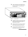
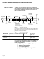
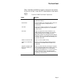
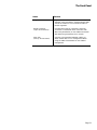
1
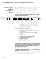
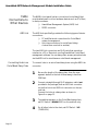
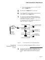
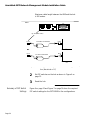
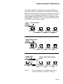
AsantéHub 2072 Network
Management Module
Installation Guide
AsantéHub 2072
Network
Management
Module Installation
Guide
• Introducing the Network Management
Module on page 4
• Installation on page 6
• The Front Panel on page 8
• Cable Connections to Other Devices
on page 12
• Using AsantéTerm on page 19
• Using Telnet on page 21
• Using the Asanté Remote Management
System on page 24
• Configuration Menu on page 31
• Segment Control on page 38
• Technical Specifications on page 41
AsantéHub 2072 Network Management Module Installation Guide
Asking
for Assistance
Asanté Technical Support
To contact Asanté Technical Support:
Telephone
(800) 622-7464
(408) 435-0706
Fax
(408) 432-6018
Fax-Back1
(800) 741-8607
(408) 954-8607
Bulletin Board Service (BBS)
(408) 432-1416
ARA BBS (guest log-in)2
(408) 894-0765
AppleLink mail3/BBS2
ASANTE.TECH
FTP Archive2
ftp.asante.com
Internet mail3
[email protected]
1.
2.
3.
Technical Support Hours
Page 2
Please request catalog of contents.
Download INDEX.TXT file for catalog of contents.
When sending email, please include your full name, U.S. mailing address, phone number, product
name, and a description of the problem.
6:00 AM to 6:00 PM Pacific Standard Time USA, Monday–Friday
Tell Us What You Think
Tell Us What You
Think
There’s always room for improvement and Asanté Technologies is
interested in your comments and suggestions about our product
user manuals. If you take the time to make suggestions, we will
take the time to read and consider your suggestions for new manual releases.
Please read through this manual and think about these questions:
❏
❏
❏
What do you like best about this manual?
What do you think is the least valuable or weakest part of this manual?
What is the most needed improvement you
would make to this manual?
Fax your comments and suggestions to:
Asanté Technical Publications at (408) 894-0363
or
E-mail them through Internet:
[email protected]
Page 3
AsantéHub 2072 Network Management Module Installation Guide
Introducing the
Network
Management
Module
The Asanté 2072 Network Management Module (NMM) provides
overall network management for the AsantéHub 2072 or
NetStacker hub. By plugging the module into any one of the
expansion slots in the chassis, the NMM works with the
AsantéView network management software to monitor and control AH2072 NMM or NetStacker modules, gather statistics, monitor network traffic, and set alarm thresholds. Figure 1 shows an
example of the NMM front panel.
SEGMENT 1
CPU
SNMP PORT
1
3
5
10
20
30
RS-232
SEGMENT 2
50 65+
1
3
5
10
20
30
AMS LINK
50 65+
OUT OF
BAND
5 10+
SETUP
PARTITION
UTILIZATION %
RESET
LINK/RECEIVE
MSG
AH2072NMM
LC = Late Collision
MC = Misaligned CRC
RF = Runts/Fragments
SM = Short Event/Missing SFD
LC MC RF SM
1
3
ASANTEVIEW
OUT-OF-BAND
TERMINATION
SEGMENT CONTROL
PRESS BOTH BUTTONS TO PROGRAM
SEG 2
UTILIZATION %
5 10+
LC MC RF SM
COLLISION %
1
3
COLLISION %
Figure 1
∆
RS232/AMS LINK
CONFIGURATION
SELECT
SLOT
CHANGE
SEGMENT
SEG 1
Asanté 2072 Network Management Module (NMM)
You do not have to have an NMM in the chassis
for the repeater modules to function properly.
The NMM’s major purpose is to manage the hub
and gather network statistics.
The primary features of the NMM include:
❏
❏
❏
❏
❏
❏
❏
❏
AsantéView management capability for in-band
and out-of-band
Simple Network Management Protocol (SNMP)
support
Segment control
Remote network management via RS232
Terminal connection via RS232
Comprehensive LEDs
Upgrading capabilities
Hub Alert Audio/Visual Aid
Interfacing with AsantéView network management software, the
NMM allows you to proactively manage your network via in-band
and out-of-band management from either Apple Macintosh® or
Microsoft Windows® PC platforms.
The NMM has built-in SNMP support. When running AsantéView
management software from a Macinosh or PC, you can control the
AsantéHub 2072or NetStacker hub.
The NMM also supports both management information base (MIB)
I and II, as well as Asanté’s private MIB extension.
Page 4
Introducing the Network Management Module
With the NMM’s Segment Control buttons, you can manually isolate any AH2072 NMM or NetStacker module, or assign it to either
of the chassis’ two segments.This can also be accomplished
remotely using AsantéView In-Band and Out-of-Band software.
Segment Control allows you to monitor and control both segments of the AsantéHub 2072 and its repeater modules.
The module’s RS232 port and its AsantéView Management Station
(AMS) Link offer remote (out-of-band) network management control. With these two connections and an AsantéView Management
Station, you can gather statistics and set parameters for as many as
twelve daisy-chained Asanté hubs.You can also use the RS232 port
as a local management port. Used in this way with terminal emulation software, you can gather statistics and set parameters for an
individual Asanté hub.
LEDs for both Ethernet segments are displayed on the NMM front
panel or can be viewed from an AsantéView Management Station.
The LEDs display many types of traffic statistics, such as late collisions, misalignments, fragments, and short events, as well as segment utilization and collision percentages in bar graph form.
The NMM is easy to upgrade because it has Flash EEPROM memory.To upgrade to the latest hub software (image code), download
the NMM’s microcode upgrades from an AsantéView Management
Station or from a third party TFTP server directly through the network. See the appropriate AsantéView User’s Guide or third-party
server documentation for more information on the upgrade procedure.
The AsantéHub 2072 MIB is a text file distributed by Asanté Technical Support.The file can also be obtained using anonymous FTP
(File Transfer Protocol) from Asanté’s Internet accessible FTP
server (see "Asanté Technical Support" on page 2 for more information).
For MIB compilation instructions, refer to your management console’s documentation.
Page 5
AsantéHub 2072 Network Management Module Installation Guide
Installation
The NMM installation consists of:
❏
❏
❏
❏
Grounding Requirements
Checking Package
Contents
Grounding yourself
Checking package contents
Installing the module and checking its LEDs
Connecting the module to other devices
Before unpacking or handling the module, you must attach the
grounding strap (provided in the package) to your wrist to discharge static electricity from your body or clothes. Attach the
clamp end to the hub chassis, which should already be grounded
properly.
The Asanté AH2072 NMM package contains the following items:
❏
❏
❏
Warranty card
This installation guide
AsantéHub 2072 NMM in anti-static packaging
There may also be a “Read Me First” sheet in the package. Always
read the “Read Me First” document before you install. It contains
the most up-to-date information about your installation (this information may not be included in the manual).
Warranty Card
Installing the NMM
Filling out your warranty card and sending it in promptly is important. If you do not send it in within 30 days after the date of purchase, you may not be eligible for the NMM’s 5-year warranty.
This installation assumes that you have already installed the
AsantéHub 2072 or NetStacker chassis.To install the NMM, do the
following steps:
1
Observing the anti-static grounding procedures (see
“Grounding Requirements” earlier in this document),
remove the module from its anti-static packing.
∆
▲
Page 6
Handle the module only by its edges. Do not
touch chips or connectors.
Do not force the module into a slot. Forcing the
module into a slot can damage the backplane.
Installation
2
Align the module with the inside edges of the card
guides on any available slot in the chassis. Gently slide
the module in until you can begin tightening the
screws. See Figure 2.
SEGMENT 1
CPU
UPLINK 0
AUI
AH2072NMM
AH2072H12-RJ45
MSG
1
SNMP PORT
PARTITION
RESET
1
LINK/RECEIVE
2
3
PARTITION
4
3
5
10 11 12
LC MC RF SM
1
3
1
3 3 5
10 20 4 30 50 65+
5
1
3
1
2
3
4
5
6
7
8
10
ASANTEVIEW
11
OUT-OF-BAND
TERMINATION
SEGMENT
CONTROL
12
PRESS BOTH BUTTONS TO PROGRAM
SELECT
SLOT
2
3
4
5
6
7
8
9
10
11
2
3
4
5
6
7
8
AH2072H12-RJ45
10
11
12
SEG 0
10BASET PORTS
2
3
4
5
6
7
8
9
10
11
12
SEG1
9
10
11
12
SEG 0
10BASET PORTS
1
2
3
4
5
6
7
PARTITION
1
2
3
4
5
6
7
8
SEG 1
CHANGE
SEG 0SEGMENT
12
PARTITION
1
SEG 2
SEG1
RS232/AMS LINK
CONFIGURATION
SEG1
9
1
UPLINK 0
AUI
9
COLLISION %
LINK/RECEIVE
UPLINK 0
AUI
OUT OF
BAND8
SETUP
LINK/RECEIVE
8
9
10
11
12
SEG1
9
10
11
12
LINK/RECEIVE
Figure 2
AMS LINK
7
5 10+
PARTITION
AH2072H12-RJ45
AH2072H12-RJ45
6
UTILIZATION %
LC MC RF SM
10BASET PORTS
1
UPLINK 0
AUI
2
5 10+
COLLISION %
LINK/RECEIVE
RS-232
SEGMENT 2
1 50 65+
10 20 30
UTILIZATION %
LC = Late Collision
5 = Misaligned
6
7 CRC8
9
MC
RF = Runts/Fragments
SM = Short Event/Missing SFD
SEG 0
10BASET PORTS
Installing the NMM
3
Hand-tighten the module to the chassis. Make sure you
fasten both spring-loaded screws in unison and apply
the same amount of torque so that the module
attaches evenly to the chassis.
4
If the power to the hub was on when you installed the
NMM, reset the hub. If you powered down the hub
before installing the NMM, power up at this point.
5
Check that the CPU LED (located to the right of the
Reset button) blinks. A blinking CPU LED indicates
that the NMM is functioning properly.
Page 7
AsantéHub 2072 Network Management Module Installation Guide
The Front Panel
The NMM front panel has several LEDs, ports, connectors, and
switches, all used to monitor and maintain network activity and to
enable network management capabilities. Figure 3 shows the
parts of the NMM front panel.
DIP Switch 1
ASANTEVIEW
OUT-OF-BAND
TERMINATION
CPU LED
Out-of-Band LED
SNMP Port
Partition
LED
thernet Address
SEGMENT 1
CPU
SNMP PORT
AMS Link
Ports
Utilization%
LEDs
1
3
5
10
20
30
RS-232
SEGMENT 2
50 65+
1
3
5
10
20
30
AMS LINK
50 65+
OUT OF
BAND
5 10+
SETUP
PARTITION
UTILIZATION %
RESET
LINK/RECEIVE
MSG
AH2072NMM
LC = Late Collision
MC = Misaligned CRC
RF = Runts/Fragments
SM = Short Event/Missing SFD
SNMP
Link/Receive
LED
Reset
Button
MSG LED
LC MC RF SM
1
3
SEG 2
LED
Select Slot
Button
ASANTEVIEW
OUT-OF-BAND
TERMINATION
SEGMENT CONTROL
PRESS BOTH BUTTONS TO PROGRAM
SEG 2
UTILIZATION %
5 10+
LC MC RF SM
COLLISION %
1
3
COLLISION %
SETUP
LED
Collision%
LEDs
LC=Late/Collision
MC=Misaligned CRC
RF=Runts/Fragments
SM=Short Event/Missing SFD
Figure 3
RS232/AMS LINK
CONFIGURATION
RS232
Connector
DIP Switch 2
RS232/AMS LINK
CONFIGURATION
SELECT
SLOT
CHANGE
SEGMENT
Change
Segment
Button
SEG 1
SEG 1
LED
The NMM Front Panel
Some earlier models of the 2072 NMM have different DIP Switch
labels. Table 1 gives a summary of the names used on the front
panel and in the documentation.
Table 1
DIP Switch 1
NMM DIP Switch Labels
ASANTEVIEW OUT-OF-BAND TERMINATION
AMS LINK
DOWN = END
(on the left)
DIP Switch 2
UP = THROUGH
RS232/AMS LINK CONFIGURATION
RS232
UP = AMS PORT
DOWN = SETUP
(on the right)
LEDs on the front panel display the status of the hub, NMM CPU,
and segment traffic (Segment 1 or Segment 2).The LEDs are
divided into five categories:
❏
❏
❏
❏
Page 8
NMM and segment status (CPU to utilization)
Segment collision percentage
Out-of-band and Setup status
Segment Control (Segment 1 or Segment 2 or
none)
The Front Panel
Table 2 identifies the NMM front panel components and explains
the function of each. It also lists LED interpretations where appropriate.
Table 2
Function of NMM Front Panel Components
Name
Function
Ethernet MAC Address
The physical address of this module and hub;
preset at the factory.
Reset button
Resets the NMM only (interrupts traffic). When the
module resets, power on diagnostics run
automatically.
CPU LED
Flashes when there is module or hub CPU activity;
if this LED is continuously off or on, a hardware
problem exists.
MSG LED
Lights to indicate one of two conditions: 1) an
SNMP message may be waiting; if so, check the
System Message area of the Network Alerts
(Macintosh) window in AsantéView (Event Reports
window on the PC). 2) a checksum error may have
occurred in the image file when downloading; if so,
repeat the download.
SNMP Port Partition LED
Lights to indicate SNMP activity.
SNMP Port Link/Receive
LED
Blinks to indicate that SNMP packets are being
transmitted to the NMM when an SNMP link is
established.
Segment Utilization LEDs
(top row of 8 LEDs per
segment)
Lights to indicate the total percentage of segment
(not module) bandwidth being utilized at any time
on the specified segment (1 or 2). Bar display
indicates hub utilization at 1, 3, 5, 10, 20, 30, 50, or
65+%, reported per 0.25 or 0.5 second. Green
indicates 1 to 20%; amber indicates 30-50%; and
red blinking indicates 65+%.
Page 9
AsantéHub 2072 Network Management Module Installation Guide
Name
Page 10
Function
Hub Status LEDs
(bottom row of 8 LEDs
per segment)
Provides warning and packet collision data about
the segment (not the module); the first four are
warning LEDs, the second four provide the total
percentage of packet collisions occurring at any
instant on Segment 1 or Segment 2.
LC - Late Collision. A collision which occurs after
the 64 byte Collision window
MC - Misaligned/CRC. This received data frame
was not an integer multiple of eight bits (or one
byte).
RF - Runts/Fragments. This frame is greater than
two bytes and less than 64 bytes, has a Start
Frame Delimiter, and has a bad Frame Check
Sequence (CRC) error).
SM - Short Event/Missing SFD. This data frame is
less than ten bytes and does not have a Start
Frame Delimiter.
Out-of-Band LED
Flashes when Out-of-Band is in use with the AMS
Link (RJ-45) only. Note: This only functions when
the NMM is in operational mode.
SETUP LED
Lights continuously to indicate DB-9/RS232 is
being used for setup (DIP Switch 2 in DOWN
position).
Flashes when management station running AMS is
communicating through the DB-9/RS232 (Out-ofBand) connection.
ASANTEVIEW OUT-OFBAND TERMINATION
(DIP Switch 1)
Terminates the Out-of-Band daisy-chain. The end
hub in the chain must be terminated. If only one
hub is in the chain, set this switch to the DOWN
position.
RS232/AMS LINK
CONFIGURATION
(DIP Switch 2)
Indicates (switch is set to UP position) RS232 is
being used with AsantéView Out-of-Band.
Switch set to DOWN position indicates RS232 is
used for terminal mode or when AsantéView Outof-Band is connected using the RS232 port on the
NMM.
Select Slot button
Lets you select a particular module and then use
the Change Segment button to place the module
on a different segment.
Change Segment button
Lets you place the selected module on Segment 1,
Segment 2, or neither segment.
Segment 1 LED
Lights to indicate that the module is currently on
Segment 1 of the backplane. Segment 1 is the
default setting. If both Segment LEDs are off, the
module is not connected to either of the two
segments.
The Front Panel
Name
Function
Segment 2 LED
Lights to indicate that the module is currently on
Segment 2 of the backplane. If both Segment LEDs
are off, the module is not connected to either of
the two segments.
RS232 Connector
(9-pin serial interface)
Provides three types of connections: terminal
connection, Out-of-Band direct connection with
AMS using AsantéView, or Out-of-Band connection
with AMS using AsantéView via a modem.
AMS Link
(two RJ-45 connectors)
Connects, using standard 10BaseT cabling, to
either another hub or to a management station
using the AMS Link Extender for Out-of-Band
management.
Page 11
AsantéHub 2072 Network Management Module Installation Guide
Cable
Connections to
Other Devices
The NMM’s front panel has two connections (out-of-band) that
provide attachment to other hardware devices such as PCs, Macs,
or dial-up modems:
❏
❏
AMS Link
AsantéView Management System (AMS) Link
RS232 connector
The AMS Link specifically provides the following types of device
connections:
❏
❏
PC and Macintosh connections for Out-of-Band
network management
Hub interconnections for out-of-band (daisychained from one hub to another)
The two AMS Link connectors are RJ-45 ports that provide an
interface to a PC or Macintosh running AsantéView Out-of-Band
management software.You can daisy-chain as many as twelve hubs
via the AMS Link for simultaneous out-of-band management.
Connecting Hubs in an
Out-of-Band Daisy-Chain
Page 12
To connect hubs in an out-of-band daisy-chain using the AMS Link
connector:
1
Be sure the length of the daisy-chain, from the management station to the hub furthest away, is less than
2000 feet.
2
Connect a straight-through RJ-45 extension cable (not
provided in the package) from an AMS Link connector
on the first hub to an AMS Link connector on the second hub.
Connect the hubs in a daisy-chain as shown in
Figure 4 on page 13.
3
To enable termination in the Out-of-Band daisy-chain,
set DIP Switch 1 DOWN (END) on the end hub only.
4
On all other hubs in the chain, set DIP Switch 1 UP
(THROUGH).
Cable Connections to Other Devices
∆
If you are managing only one hub, set DIP
Switch 1 DOWN (END).
5
6
Set DIP Switch 2 DOWN (SETUP) on all hubs.
7
To connect an AsantéView Management Station to a
hub, follow the instructions in "Connecting a Management Station to the Hub" on page 13.
For a summary of DIP switch settings, see Figure 6 on
page 15 and Figure 7 on page 16.
If you change a DIP switch setting, you must reset the
hub or NMM. Press the Reset button.
DIP Switch 2 DOWN
(SETUP) on all hubs
Mac or PC
AMS Link
Extender
RJ45
Hub 1
DIP Switch 1 UP
(THROUGH)
on all other hubs
to Mac or PC
AsantéView
Management
Station (AMS)
Hub 2
1 2
DIP Switch 1
DOWN (END)
on end hub only
End Hub
Figure 4
Connecting a
Management Station to
the Hub
1 2
1 2
Connecting hubs in an Out-of-Band daisy-chain
To connect an AsantéView Management Station to the hub:
1
Connect one end of the AMS Link Extender to a PC or
Macintosh and the other end to an AMS Link connector port. Figure 5 shows how to make this connection.
Page 13
AsantéHub 2072 Network Management Module Installation Guide
Maximum cable length between the AMS and the hub
is 100 meters.
NMM
RS-232
1
2
RS-232
RJ-45 (AMS LINK)
RJ-45
Mac AMS Link Extender
DIN-8
or
Mac
RJ-45
PC AMS Link Extender
DB-9
PC
Figure 5
Summary of DIP Switch
Settings
Page 14
Using an AMS Link port to connect to a Management Station (Macintosh or PC)
2
Set DIP switches on the hub as shown in Figure 4 on
page 13.
3
Reset the hub.
Figure 6 on page 15 and Figure 7 on page 16 show the required
DIP switch settings for the 2072 NMM in five configurations.
Cable Connections to Other Devices
In the first Out-of-Band configuration, the AsantéView Management Station (AMS) is connected to a hub using one of the hub’s
AMS Link ports and an AMS Link Extender. In the second, the AMS
is directly connected to a hub using the hub’s RS232 connector
and a straight-through RS232 cable.The third configuration shows
a remote AMS connected to a hub over telephone lines using the
hub’s RS232 connector and a modem.
AMS
AMS
AMS Link Extender
1 2
1 2
1 2
1 2
Hub
Hub
Hub
Hub
RJ-45
AMS
RJ-45
Straight-through
RS232
1 2
1 2
1 2
1 2
Hub
Hub
Hub
Hub
RJ-45
AMS
RJ-45
RS232
RJ-45
RJ-45
Public Switched Telephone Network
(PSTN)
modem
RS232
1 2
Hub
modem
RJ-45
Figure 6
1 2
1 2
1 2
Hub
Hub
Hub
RJ-45
RJ-45
DIP switch settings for Out-of-Band using AMS Link
Extender, RS232 direct, and RS232 with modem
Page 15
AsantéHub 2072 Network Management Module Installation Guide
The fourth configuration connects a terminal to an individual hub
using the RS232 connector as a local management port.The fifth
configuration connects an AMS to a single hub using one of the
hub’s AMS Link ports and an AMS Link Extender.
Straight-through RS232
Terminal
only this device
is managed
Configuration 4
Local management port
1 2
1 2
1 2
1 2
Hub
Hub
Hub
Hub
Ethernet backbone
AMS
AMS
AMS Link Extender
Configuration 5
Out-of-Band single hub
1 2
Hub
Figure 7
Connecting a Modem to
the Hub
Page 16
DIP switch settings for Local Management Port, and AMS
Link Extender with single hub
For remote management purposes, you can make a local connection from the RS232 serial port on the NMM to a modem.You can
use this setup with AsantéView and the AsantéView Management
Station (AMS) to activate a pager when it receives a trap message
from a hub.This trap message causes the AMS to page this event to
the remote user. See the appropriate AsantéView User’s Guide for
information on setting up trap messages and paging options.
Cable Connections to Other Devices
To connect the hub to a modem, do the following:
1
2
3
Using the Local
Management Port
Connect the modem only to the end hub.
Set DIP Switch 2 UP for this hub.You will not be able
to manage this hub using AsantéView Out-of-Band via
the AMS Link while this switch is in the UP position.
Set up the modem for auto-answer.
You can use the RS232 connector on the NMM as a local management port.This section describes the steps involved.They are:
❏
❏
Preparing the hub
Connecting to the local management port
To prepare the hub for communication via the local management
port:
1
Set the hub’s DIP Switch 2 DOWN as shown in
Figure 8.
DIP Switch 1
ASANTEVIEW
OUT-OF-BAND
TERMINATION
DIP Switch 2
RS232/AMS LINK
CONFIGURATION
Set to
DOWN position
(DOWN = SETUP)
Figure 8
RS232/AMS Link Configuration DIP Switch Setting
DIP Switch 1 can be set to either UP or DOWN.
2
Reset the hub after changing the DIP switch setting by
pressing the Reset button on the NMM front panel.
Follow these steps to connect an RS232 cable to the local management port.
Page 17
AsantéHub 2072 Network Management Module Installation Guide
1
Connect a straight-through RS232 cable to the RS232
connector on the NMM.
Figure 9 shows a Macintosh RS232 cable being connected to the NMM RS232 connector.
UTILIZATION %
CPU
SNMP PORT
1
3
5
10
20
30
RS-232
UTILIZATION %
50 65+
1
3
5
10
20
30
AMS LINK
50 65+
OUT OF
BAND
5 10+
SETUP
PARTITION
SEGMENT O
RESET
LINK/RECEIVE
MSG
AH2072NMM
LC = Late Collision
MC = Misaligned CRC
RF = Runts/Fragments
SM = Short Event/Missing SFD
LC MC RF SM
1
3
SEGMENT CONTROL
ASANTEVIEW
OUT-OF-BAND
TERMINATION
PRESS BOTH BUTTONS TO PROGRAM
SEG1
SEGMENT 1
5 10+
COLLISION %
LC MC RF SM
1
3
COLLISION %
RS232/AMS LINK
CONFIGURATION
SELECT
SLOT
CHANGE
SEGMENT
SEG 0
RS 232
DIN-8
To MAC
Figure 9
2
Connect the other end of the RS232 connector to the
modem or COM port on the back of the AMS.
The Macintosh uses the symbol shown in Figure 10 to
indicate the modem port.
Figure 10
Page 18
Connecting to the Hub
Macintosh Modem Port Symbol
Using AsantéTerm
Using AsantéTerm
Installing AsantéTerm
AsantéTerm, provided with AsantéView In-Band and Out-of-Band,
can be used to interrogate and program an Asanté hub using the
Macintosh as a terminal.
Follow this procedure to install AsantéTerm.
1
Insert the AsantéView disk into the floppy drive and
double-click the disk icon to open it.
2
Copy the AsantéTerm program to your hard drive.The
icon looks like the one shown in Figure 11.
Figure 11
Running AsantéTerm
AsantéTerm Icon
To start AsantéTerm, use the following procedure.
1
Double-click the AsantéTerm icon.
AsantéTerm opens the terminal window.There may
not be any data displayed in the window after opening
it.
2
Press return to start communication with the hub.
Figure 12 shows the screen that appears for interrogating and programming an AsantéHub 2072.
Page 19
AsantéHub 2072 Network Management Module Installation Guide
Figure 12
Page 20
Asanté Remote Management System Main Menu using
AsantéTerm
Using Telnet
Using Telnet
You can use Telnet to interrogate and program an AH2072 NMM
NMM with a NetStacker hub or AsantéHub 2072.You can do this
using any Telnet-capable computer, either directly connected to
the hub or over the network.
∆
Information on installing Telnet is not provided in
this manual. Refer to the documentation that
comes with the Telnet software.
The following list is a summary of the steps you need to perform
to use Telnet with an AH2072 NMM connected to a NetStacker
hub or an AsantéHub 2072.
❏
❏
❏
Install the image code on the AMS
Upgrade the hub’s image code
Establish a link with the hub using Telnet
This procedure assumes you‘ve already done the following:
❏
❏
❏
❏
❏
Installed AsantéView In-Band or Out-of-Band software on the AMS
Connected appropriate cables for In-Band or
Out-of-Band management
Set hub DIP Switches if needed
Assigned an IP address to the hub
Installed the Telnet application on your network
management station
Refer to the Telnet software documentation for installation
instructions. See the appropriate AsantéView User’s Guide for
information on installing and configuring the appropriate software and hardware for using AsantéView.
Installing the Image Code
Before you upgrade the image code in the AH2072 NMM with a
NetStacker hub or AsantéHub 2072, you need to install the image
code files on the AMS. Table 3 lists the files you need.
Table 3
Image Code File Names
AsantéHub 2072
2072huxx.17x or higher
2072h.cfg
Page 21
AsantéHub 2072 Network Management Module Installation Guide
Copy the files to the AMS Images folder on the Macintosh. On the
PC, copy the files to the same directory as the AMS executable
(In-Band or Out-of-Band).
Upgrading the Hub
Image Code
You can download the image code to the hub using either
AsantéView In-Band or Out-of-Band.You do this by selecting the
Software Upgrade command in the Configuration menu. See the
appropriate AsantéView User’s Guide for information on performing software upgrades.
The following image code versions support Telnet:
❏
Starting Telnet
The following instructions show how to start the Telnet application and get to the Asanté Remote Management System Main Menu
using a Macintosh computer.The examples show screens for a
Macintosh using NCSA/BYU Telnet version 2.5.
1
Open the Telnet application by double-clicking its
icon. Figure 13 shows the icon for NCSA/BYU Telnet
version 2.5 on a Macintosh.
Figure 13
Page 22
version 1.7 or higher for the AsantéHub 2072
Icon for NCSA/BYU Telnet 2.5 (Macintosh)
2
Choose Open Connection from the File menu.The session dialog appears. Figure 14 shows an example.
3
Select the Session name field and type the IP address
of the hub you want to configure. Figure 14 shows an
example with the IP address already typed in.
Using Telnet
Figure 14
4
Sample Telnet Session Dialog
Click the OK button. Figure 15 shows the Asanté
Remote Management System Main Menu that appears
for configuring an AsantéHub 2072.
Figure 15
Asanté Remote Management System Main Menu using
Telnet
Page 23
AsantéHub 2072 Network Management Module Installation Guide
Using the Asanté
Remote
Management
System
This section contains:
❏
❏
∆
General Guidelines
The icons, menus, and screens for accessing the
Asanté Remote Management System may differ
depending on what computer you’re using. Once
you’re in the Asanté Remote Management System,
the menus look the same.
Here are some general guidelines for using the Asanté Remote
Management System menus:
❏
❏
❏
❏
❏
❏
❏
❏
Page 24
General guidelines for using the Asanté Remote
Management System menus
A short tutorial for navigating the system menus
To invoke a command, type the letter of the
alphabet listed in the <Cmd> column in the Configuration menu (don’t type < >).There’s no need
to press the Return key after typing the letter.
When you press c for the Configuration menu,
you’re prompted for a password.The default password is Asante (the password is case-sensitive).
Type the password, then press the Return key.
When you input or change data, you do need to
press the Return key to send the change to the
hub.
If you go into a data input area that’s blank and
want to leave it blank, just press the Return key.
If you go into a data input area and want to leave
the field’s contents as-is, you have to retype the
entire line (pressing the Return key deletes everything on that line).
Typically you press q to leave the menu you’re on.
You’re returned to the previous menu.
Pressing q at the Asanté Remote Management System Main menu closes the Telnet connection
with the hub.
Choosing Quit from the File menu closes the Telnet application.
Using the Asanté Remote Management System
Asanté Remote
Management System
Menu Tutorial
The following short tutorial navigates through some of the Asanté
Remote Management System menus.The tutorial adds the text
“2072” to a hub’s previously-defined name. All examples show Telnet running on a Macintosh.
We start with a Telnet session established with an
AsantéHub 2072.The Asanté Remote Management System Main
menu appears, shown in Figure 16.
Figure 16
1
Asanté Remote Management System Main Menu
(Tutorial)
Type g to show the current configuration. Figure 17
shows an example.
Page 25
AsantéHub 2072 Network Management Module Installation Guide
Figure 17
Example General Configuration Screen
The example shows “Office Hub” as the current hub
name. If the hub has not had a name assigned to it previously, the Hub Name field will be blank.
Page 26
2
Press the space bar to continue.The Asanté Remote
Management System Main menu appears again (see
Figure 16 on page 25).
3
Type c from the Asanté Remote Management System
Main menu.The prompt “Enter Password” appears
below the Command> line, shown in Figure 18.
Using the Asanté Remote Management System
Figure 18
4
Enter Password Prompt
Type the password Asante (the password is case-sensitive) and press return.
The Configuration menu appears, shown in Figure 19.
Figure 19
Configuration Menu
Page 27
AsantéHub 2072 Network Management Module Installation Guide
5
Type a from the Configuration menu.This takes you to
the System Administration Information menu, shown
in Figure 20.
Figure 20
System Administration Information Menu
Note that the current hub information—name, contact, and location—displays above the menu choices
on this screen (some or all of these fields may be blank
for your particular hub).
We’ll change the example hub’s current name,“Office
Hub”, to “Office Hub 2072.” (You can type a different
name if you wish.)
6
Page 28
Type n to set the hub’s name.The Command> line
changes to prompt you for the new name, as shown in
Figure 21.
Using the Asanté Remote Management System
Figure 21
7
Enter Hub Name Prompt
Type Office Hub 2072 (or a different name if you wish)
and press return.
Note in the above example that even though it looks
like we could just add the text “2072” to the end of the
hub name, we actually have to type the entire line. If
we typed “2072” only, the hub would be renamed
“2072” rather than “Office Hub 2072”.
Telnet sends the new name to the hub and the screen
refreshes to display the current information. Figure 22
shows the new hub name,“Office Hub 2072”, used in
this example.
Page 29
AsantéHub 2072 Network Management Module Installation Guide
Figure 22
8
9
System Administration Information Menu Showing New
Hub Name
Press q to return to the Configuration menu.
Press q again to return to the Asanté Remote Management System Main menu.
You’ve just completed the tutorial for navigating menus in the
Asanté Remote Management System. If you want to leave the Telnet application at this time, choose Quit from the File menu. Or,
you can stay in the Asanté Remote Management System and go on
to the next section, which describes Configuration menu items
you can use to configure your hub.
Page 30
Configuration Menu
Configuration
Menu
This section shows you how to access the Asanté Remote Management System Configuration menu and then describes the menu
choices you can use to configure your hub.
All examples show Telnet running on a Macintosh. We start with a
Telnet session established with an AsantéHub 2072.
Accessing the
Configuration Menu
Use the following procedure to get to the Configuration menu.
1
From the Asanté Remote Management System Main
menu, press c for Configuration.The prompt “Enter
Password” appears.
2
Type the default password Asante (the password is
case-sensitive) and press return.The Configuration
menu appears.
Figure 23 shows an example of the Configuration
menu for an AsantéHub 2072.
Figure 23
Configuration Menu
Descriptions
Configuration Menu example
The following paragraphs describe the Configuration menu
choices you can use to configure your hub.
Page 31
AsantéHub 2072 Network Management Module Installation Guide
System Administration Information
Use to enter and transmit text strings defining the hub name,
contact, and location.
Out-of-Band Parameters
Use to enter and transmit the Out-of-Band baud rate, dial string
to be used when the AMS dials out on a modem, and the
Out-of-Band password. Baud rate changes also will be effective
on the terminal.
The Out-of-Band password applies when you are establishing
an Out-of-Band connection with the hub using AsantéView
Out-of-Band and the RS232 port. See the appropriate AsantéView User’s Guide for more information.There is no password
checking when you use the direct link to the hub using the
AMS Link ports.
TCP/IP Parameters
Use to define the hub IP address, IP subnet mask, and default
router IP address.The new parameters take effect after you
restart the hub.
Bootstrap Parameters
Use to define where the hub should boot from (local from
EEPROM or from a remote server), what SNMP protocols
should be used during the remote boot process, and the
IP address of the remote server.
Asanté recommends that you use the default setting of local.
The Boot File Name referred to in the menu is the configuration file residing in the AsantéView AMS Images folder in the
Macintosh version, and the same directory as the AMS executable (In-Band or Out-of-Band) in the Windows version
(C:\AVIEW is the default).The default name is 2072h.cfg for the
AsantéHub 2072 See the appropriate AsantéView User’s Guide
for more information.
SNMP Parameters
Use to define a variety of SNMP parameters:
❏
Read Community string
❏
Write Community string
❏
Authentication trap
❏
Trap receiver table parameters
Page 32
Configuration Menu
Group Parameters
Use to assign to a segment or isolate, meaning assign to no segment, a group. (A group is defined as all of the ports on an
AsantéHub 2072 or NetStacker hub module.) Pressing n (Select
Next Group) repeatedly cycles through the group choices.
Pressing s (Assign/Isolate Group Segment) repeatedly cycles
through the segment choices—1, 2, or Isolated for the
AsantéHub 2072; 1 or Isolated for the NetStacker hub.
∆
▲
If you isolate a group from both segments (that is,
assigned it to no segment), you’ll lose your Telnet
connection and SNMP capabilities. You then can
manage the group only by using AsantéView Outof-Band.
If your AsantéView Management Station (AMS) is
on one segment, and you change the NMM to the
other segment, you will not be able to communicate with the NMM (provided a bridge does not
exist between the two segments). You lose your
Telnet connection and SNMP capabilities.
You can reestablish communication with the
module by changing the segment using the Select
Slot and Change Segment buttons on the hub, by
connecting your AMS to the other segment, or by
using AsantéView Out-of-Band.
Port Parameters
Use to enable/disable a specific port’s connection, link integrity, and auto polarity testing. Pressing N (uppercase N) repeatedly cycles through the available groups. Pressing n repeatedly
cycles through the ports within a group.
Node Summary
Use to display a summary of node activity on the hub.The hub
monitors all packets passing through its ports. Pressing G or g
cycles back and forth through the available groups. Pressing P
or p cycles back and forth through the ports within a group.
Pressing c (chg cntr) repeatedly cycles through the available
data counters: Good Frames, Bad Frames, Broadcast, Multicast,
Short Event, Runts, Frame Too Long, SFD Missing, Fragments,
Alignment Errors, DRM Errors, IFG Errors, Collisions, Late Collisions, Auto Partitions, MJLPs, and Readable Octets.
Page 33
AsantéHub 2072 Network Management Module Installation Guide
Pressing a sets the node summary aging time, which is the
amount of time the hub stores node summary data. Each time
a new device uses a port, or the frame type changes, the hub
stores an entry in the Node Summary log. If the hub does not
receive data again from that node within the specified aging
time, the node data is purged from the log.
▲
If the aging time is set to a short time span, problem nodes may time out and be dropped from the
Node Summary table.
Console Password
Use to set the password for the terminal interface connection.
The password is case-sensitive, and it can be up to 20 characters.You’re prompted for this password when you choose the
Configuration menu from the Asanté Remote Management System Main menu.The default password is Asante.
Telnet Idle Timeout
Use to set the length of idle time, in whole minutes, before Telnet closes the current connection.The default is 20 minutes.
To keep Telnet from timing out at all, set the idle time to zero
minutes.
Toggle Segment Switch Lock/Unlock
Use to enable/disable manual segment control. When manual
segment control is disabled, pressing the two segment control
buttons on the standard NMM faceplate does nothing.
Reset EEPROM on NMM Module to Default
Use to set user-defined settings for the NMM to their default
values.The hub name, hub contact, hub location, dial string,
and boot file name fields become blank, and the boot server
IP address is set to all zeros.These changes occur immediately.
The hub IP address, subnet mask, and default router IP address
are set to all zeros. Console Password is set back to its default,
which is Asante. Telnet Idle Timeout is also set back to its
default, which is 20 minutes.These changes occur on hub
restart.
Reset EEPROM on All Repeater Module(s) to Default
Use to set port parameters—Port Connection, Link Test, and
Auto Polarity Correction—to the default value, which is
Enabled.These changes occur immediately.
Page 34
Configuration Menu
Reset System
Use to send an immediate Reset command to the hub, causing
a soft reset.Terminal communication is lost briefly, then automatically reestablished. If you’re using Telnet, the connection
is closed.
Exit Configuration Menu
Use to leave the Configuration menu and go back to the Asanté
Remote Management System Main menu.
Changing the Password
You’re prompted for a password when you choose the Configuration menu from the Asanté Remote Management System Main
menu. (The default password is Asante.)
You can change this password if you wish.The password is casesensitive, and it can be up to 20 characters.
Use the following procedure to change the current password. All
examples show Telnet running on a Macintosh. We start with a
Telnet session established with an AsantéHub 2072.
1
From the Asanté Remote Management System Main
menu, press c for Configuration.The prompt “Enter
Password” appears.
2
Type the current password (the default password is
Asante) and press return.The Configuration menu
appears.
Figure 23 shows an example of the Configuration
menu for an AsantéHub 2072.
Page 35
AsantéHub 2072 Network Management Module Installation Guide
Figure 24
3
Type c for Console Password.
The Command> line changes to prompt you for the
new password, as shown in Figure 25.
Figure 25
4
Page 36
Configuration Menu example
Enter New Password Prompt
Type the new password and press return.You’re
prompted to type the new password again.
Configuration Menu
5
Type the new password a second time and press
return.The new password is sent to the hub and
you’re taken back to the Configuration menu.
Page 37
AsantéHub 2072 Network Management Module Installation Guide
Segment Control
The AsantéHub 2072 and NetStacker hub provide two discrete
network segment interconnections.That is, any AsantéHub 2072
or NetStacker module, including the AH2072 NMM, can be connected to Segment 1, Segment 2, or neither segment (isolated).
Segment connection assignment for any module can be done
through NMM front panel controls or with AsantéView software.
The NMM has two push-button Segment Controls: the Select Slot
and Change Segment buttons, which are located on the right of
the front panel. Figure 26 shows the location of these buttons.
RS-232
TION %
20
30
AMS LINK
50 65+
OUT OF
BAND
5 10+
SETUP
ASANTEVIEW
OUT-OF-BAND
TERMINATION
SEGMENT CONTROL
PRESS BOTH BUTTONS TO SET
SEG 2
ENT 1
1
3
COLLISION %
RS232/AMS LINK
CONFIGURATION
SELECT
SLOT
Select Slot button
Figure 26
CHANGE
SEGMENT
SEG 1
Change Segment button
Segment Control Buttons
See the AsantéView documentation for segment control procedures using AsantéView.
An Example for
Segmenting the Network
You may want to divide your network into two separate, distinct
backbones, so that traffic from one network does not interfere
with traffic or cause traffic congestion on your other network. For
example, in a campus-like environment, you may have two completely different networks (two separate backbones) independent
of each other.
Continuing with this example, Network A is an administration/faculty network and Network B is a student-operated network.The
student network is primarily used for network lab testing, which
can be highly vulnerable to periodic downtime.
However, Network A, which is solely operated by university
administration and faculty members, primarily uses its network
for record keeping and administrative tasks, and therefore, must
operate smoothly without any unnecessary student interference
from Network B.To keep the two segments isolated from each
other, the network manager can use Segment Control.
Page 38
Segment Control
Setting Segment Control
Manually
This section explains how to first select a module for a segment
change and then perform the actual segment change. Figure 27
summarizes the steps.
Change Segment button
Select Slot button
RS-232
%
0
AMS LINK
50 65+
OUT OF
BAND
5 10+
SETUP
ASANTEVIEW
OUT-OF-BAND
TERMINATION
RS232/AMS LINK
CONFIGURATION
ISION %
Step 1. Press Select Slot button until
specified slot is chosen.
SEGMENT CONTROL
PRESS BOTH BUTTONS TO SET
SELECT
SLOT
CHANGE
SEGMENT
SEG 2
SEG 1
Step 3. Press both the Select Slot and
Change Segment buttons at the same time
to set the new segment selection.
Step 2. Press Change Segment
button until specified segment is chosen.
Figure 27
∆
Selecting a Slot for Segment Change
To ensure that you maintain network management capabilities, you must make sure that your
AsantéView Management Station (AMS), which is
running AsantéView management software, is on
the same segment as the NMM. (Segment 1 is the
default setting.)
To manually select a module for segment change, complete the
following steps.
1
Press the Select Slot button.
If the NMM is set to Segment 1, pressing the Select
Slot Button causes the Segment 1 LED to flash. If the
NMM is set to Segment 2, pressing the Select Slot Button causes the Segment 2 LED to flash. If the NMM is
isolated (set to neither segment), pressing the Select
Slot Button causes both segment LEDs of the NMM
module (Seg 1 and Seg 2) to flash.
2
Continue pressing the Select Slot button until you
have chosen your specified slot.The Segment LED for
the specified slot begins flashing.
Page 39
AsantéHub 2072 Network Management Module Installation Guide
3
Press the Change Segment button repeatedly until you
have chosen the segment you want: Seg 1, Seg 2, or
neither.
4
When you have chosen your segment, press both the
Select Slot and Change Segment buttons together. In
approximately two to three seconds, the change is
made and the specified segment’s LED lights; the
unspecified segment’s LED darkens. (See Figure 27 on
page 39.)
∆
Isolating Modules from
the Network
Network statistics cannot be collected if a module is isolated from both segments.
To isolate (remove) a particular module from the network, press
both the Select Slot and Change Segment buttons simultaneously.
Both segment LEDs for the selected slot remain lit. Table 4 identifies the LED states for both segments while you are cycling
through the process (changing from one segment to another).
Table 4
Segment LED States
LED State
Meaning
Seg 1 LED, On
This particular slot is connected to Seg 1.
Seg 2 LED, On
This particular slot is connected to Seg 2.
Seg 1 & Seg 2, Off
There is no segment connection.
▲
Page 40
If your AsantéView Management Station (AMS) is
on one segment, and you change the NMM to the
other segment, you will not be able to communicate with the NMM (provided a bridge does not
exist between the two segments). You lose your
Telnet connection and SNMP capabilities.
You can reestablish communication with the
module by changing the segment using the Select
Slot and Change Segment buttons on the hub, by
connecting your AMS to the other segment, or by
using AsantéView Out-of-Band.
Technical Specifications
Technical
Specifications
Physical Dimensions:
17” x 0.9” x 12”
Weight:
Approximately 2 lbs. (2.73 kg)
Non-volatile Program Memory:
Flash EEPROM and EEPROM
Environmental Conditions:
Operating Temperature: 0° to 40° C ambient
Operating Humidity: 5 to 85% noncondensing
Operating Altitude: 10,000 ft. (3,048 m) maximum
Storage Temperature: -30° to 80° C
Storage Humidity: 5 to 90% noncondensing
Storage Altitude: 25,000 ft. (7,620 m) maximum
Warranty:
1 year
RS232 Connections
Table 5 lists the pin assignments for a standard RS232 connector.
Table 5
RS232 Connector Pin Assignments
Pin
Cable Limitations for
Out-of-Band
Function
1
Protective ground
2
Transmit data
3
Receive data
4
Request to send
5
Clear to send
6
Data set ready
7
Signal ground
8
Carrier detect
20
Data terminal ready
22
Ring indicator
The AMS link can not be more than 2000 feet between first and
last device (including the network management station) in the
chain.
Page 41
Index
Index
Symbols
<Cmd> column 24
Numerics
2072h.cfg configuration file 21, 32
2072huxx.17x image file 21
A
aging time 34
Alignment Errors 33
AMS Essentials folder 32
AMS executable 22, 32
AMS Images folder 22
AMS Link
chg cntr command 33
closing the current connection 34
closing the Telnet connection 24
Collisions 33
Community strings 32
Configuration Menu
descriptions 31
example (figure) 31, 36
password 24
procedure for accessing 31
Configuration Menu items
Bootstrap Parameters 32
Console Password 34
Exit Configuration Menu 35
Group Parameters 33
Node Summary 33
Out-of-Band Parameters 32
Port Parameters 33
Reset EEPROM on All Repeater Module(s) to Default 34
Reset EEPROM on NMM Module to Default 34
Reset System 35
SNMP Parameters 32
System Administration Information 32
TCP/IP Parameters 32
Telnet Idle Timeout 34
Toggle Segment Switch Lock/Unlock 34
cable limitations 41
connection types 12
connectors 11
AMS Link ports 32
AMS PORT/SETUP DIP Switch 10
Apple Macintosh and the NMM 4
AsantéHub 2072
configuration file 32
image code file names 21
AsantéHub 2072 MIB 5
AsantéTerm icon 19
AsantéView for Windows default directory 32
Assign/Isolate Group Segment menu item 33
assigning to a segment 33
authentication traps 32
Auto Partitions 33
Auto Polarity Correction 34
auto polarity testing, enabling/disabling 33
connecting
modem to hub 16
to local management port 17
connections, Out-of-Band 12
connectors
AMS Link 11
RS-232 11
B
Bad Frames 33
baud rate, Out-of-Band 32
boot file name 32, 34
boot server IP address 34
Bootstrap Parameters menu item 32
Broadcast 33
buttons
Change Segment 10, 38, 40
Select Slot 10, 38, 39
C
C:\AVIEW directory 32
cable limitations, Out-of-Band 41
case-sensitivity of password field 24
Change Segment button 10, 38, 40
changing segments 40
Console Password menu item 34
CPU Activity LED 9
CPU LED
during installation 7
current configuration, displaying 26
current hub information 28
D
daisy-chaining hubs
and AMS Link connectors 12
examples 14
default router IP address 32, 34
defaults
directory, AsantéView for Windows 32
hub boot 32
NMM 34
Index i
Index
password 34, 35
port parameters 34
segments 10, 39
defining hub IP address 32
dial string 32, 34
DIP Switches
AMS PORT/SETUP 10
settings
communicating with AsantéTerm 17
modem connected to hub 17
Out-of-Band daisychain 12
summary 14, 15
THROUGH/END 10
disabling port parameters 33
disabling termination 12
displaying current configuration 26
DRM Errors 33
E
EEPROM
local boot from 32
non-volatile program memory 41
resetting on NMM module 34
hubs, daisy-chaining
and AMS Link connectors 12
examples 14
I
idle time 34
idle timeout, Telnet 34
IFG Errors 33
image code versions 21
installing the NMM
grounding requirements 6
package contents 6
invoking a command 24
IP address
hub 23, 34
remote server 32
IP subnet mask, defining 32
isolating a segment 33
isolating modules 40
L
Late Collisions 33
LEDs
enabling port parameters 33
enabling termination 12
“Enter Password” prompt 27
environmental conditions for NMM 41
Ethernet (MAC) address 9
Exit Configuration Menu menu item 35
CPU Activity 9
Hub Status 10
MSG 9
Out-of-Band 10
Segment 1 (SEG1) 10
Segment 2 (SEG2) 11
Segment Utilization 9
SETUP 10
SNMP Port Link/Receive 9
SNMP Port Partition 9
while changing segments 40
F
Flash EEPROM 41
Fragments 33
Frame Too Long 33
Good Frames 33
grounding requirements 6
Group Parameters menu item 33
limitations, cable 41
link integrity, enabling/disabling 33
Link Test 34
local boot 32
H
M
G
hub boot location 32
hub contact 28, 34
hub IP address
default 34
defining 32
hub location 28, 34
hub name 28, 34
Hub Status LED 10
Index ii
MAC address 9
Macintosh
and the NMM 4
using as a terminal 19
main menu, Asanté Remote Management System
example (figure) 23
in tutorial 25
manual segment control 34
Index
MIB
AsantéHub 2072 5
support 4
pin assignments, RS-232 port 41
port connection
default 34
enabling/disabling 33
Microsoft Windows and the NMM 4
MJLPs 33
modules, isolating 40
MSG LED 9
Multicast 33
Port Parameters menu item 33
port parameters, default values 34
prerequisites
N
R
NCSA/BYU Telnet version 2.5 22
network statistics 40
NMM
Read Community string 32
Readable Octets 33
remote boot process 32
Remote Management System main menu
DIP Switch labels 8
features 4
front panel (figure) 8
front panel component functions 9
installation 6
platforms 4
technical specifications 41
upgrading 5
NMM default values 34
Node Summary menu item 33
non-volatile program memory 41
O
Open Connection command 22
opening a connection 22
Out-of-Band
baud rate 32
connections 12
LED 10
password 32
Quick Start 21
accessing 22
example (figure) 23
Remote Management System menu
tutorial 25
remote server boot 32
remote server IP address 32
removing a module from the network 40
Reset button 9, 13, 17
Reset EEPROM on All Repeater Module(s) to Default menu item 34
Reset EEPROM on NMM Module to Default
menu item 34
Reset System menu item 35
RJ-45 ports
as AMS Link connectors 12
function 11
router, default IP address 32
RS-232 port
Out-of-Band Parameters menu item 32
connection types 11
pin assignments 41
and remote network management 4
and SETUP LED 10
P
parameters, setting
bootstrap 32
Group 33
Out-of-Band 32
Port 33
SNMP 32
TCP/IP 32
trap receiver table 32
password
Configuration Menu 24
console 34
default 34, 35
field 24
tutorial 27
physical dimensions of NMM 41
Runts 33
S
Segment 1 (SEG1) LED 10, 40
Segment 2 (SEG2) LED 11, 40
segment collision percentage 8
Segment Control
buttons 5
LEDs 8
setting manually 39
segment control, manual 34
segment status 8
Segment Utilization LEDs 9
Index iii
Index
segmenting the network, example 38
segments, LEDs while changing 40
Select Next Group menu item 33
Select Slot button 10, 38, 39
serial interface 11
session dialog 22
Session name field 23
setting hub name 29
SETUP LED 10
SFD Missing 33
Short Event 33
SNMP
NMM support for 4
Port Link/Receive LED 9
Port Partition LED 9
SNMP Parameters menu item 32
SNMP protocols during remote boot 32
soft reset 35
Software Upgrade command 22
starting Telnet 22
subnet mask
default 34
defining 32
summary, node 33
System Administration Information Menu
description 32
example (figure) 28
system, resetting 35
T
TCP/IP Parameters menu item 32
Telnet application
icon 22
quitting 24
Telnet Idle Timeout menu item 34
terminal interface connection password 34
termination, disabling and enabling 12
testing auto polarity 33
TFTP server 5
THROUGH/END DIP Switch 10
Toggle Segment Switch Lock/Unlock menu item
34
trap receiver table parameters 32
tutorial, Asanté Remote Management System
menus 25
U
using Macintosh as a terminal 19
Index iv
V
versions, image code 21
W
warranty, NMM 41
weight of NMM 41
Windows application and the NMM 4
Write Community string 32