1
Short Form Guide
Unidrive SP
Part Number: 0471-0162-02
Issue: 2
www.controltechniques.com
General Information
The manufacturer accepts no liability for any consequences resulting from inappropriate, negligent or
incorrect installation or adjustment of the optional operating parameters of the equipment or from
mismatching the variable speed drive with the motor.
The contents of this guide are believed to be correct at the time of printing. In the interests of a commitment
to a policy of continuous development and improvement, the manufacturer reserves the right to change the
specification of the product or its performance, or the contents of the guide, without notice.
All rights reserved. No parts of this guide may be reproduced or transmitted in any form or by any means,
electrical or mechanical including photocopying, recording or by an information storage or retrieval system,
without permission in writing from the publisher.
Drive software version
This product is supplied with the latest software version. If this drive is to be connected to an existing system
or machine, all drive software versions should be verified to confirm the same functionality as drives of the
same model already present. This may also apply to drives returned from a Control Techniques Service
Centre or Repair Centre. If there is any doubt please contact the supplier of the product.
The software version of the drive can be checked by looking at Pr 11.29 (or Pr 0.50) and Pr 11.34. This
takes the form of xx.yy.zz where Pr 11.29 displays xx.yy and Pr 11.34 displays zz. (e.g. for software version
01.01.00, Pr 11.29 = 1.01 and Pr 11.34 displays 0).
Environmental statement
Control Techniques is committed to minimising the environmental impacts of its manufacturing operations
and of its products throughout their life cycle. To this end, we operate an Environmental Management
System (EMS) which is certified to the International Standard ISO 14001. Further information on the EMS,
our Environmental Policy and other relevant information is available on request, or can be found at
www.greendrives.com.
The electronic variable-speed drives manufactured by Control Techniques have the potential to save
energy and (through increased machine/process efficiency) reduce raw material consumption and scrap
throughout their long working lifetime. In typical applications, these positive environmental effects far
outweigh the negative impacts of product manufacture and end-of-life disposal.
Nevertheless, when the products eventually reach the end of their useful life, they must not be discarded
but should instead be recycled by a specialist recycler of electronic equipment. Recyclers will find the
products easy to dismantle into their major component parts for efficient recycling. Many parts snap
together and can be separated without the use of tools, while other parts are secured with conventional
fasteners. Virtually all parts of the product are suitable for recycling.
Product packaging is of good quality and can be re-used. Large products are packed in wooden crates,
while smaller products come in strong cardboard cartons which themselves have a high recycled fibre
content. If not re-used, these containers can be recycled. Polythene, used on the protective film and bags
for wrapping product, can be recycled in the same way. Control Techniques' packaging strategy favours
easily-recyclable materials of low environmental impact, and regular reviews identify opportunities for
improvement.
When preparing to recycle or dispose of any product or packaging, please observe local legislation and
best practice.
REACH legislation
EC Regulation 1907/2006 on the Registration, Evaluation, Authorisation and restriction of Chemicals
(REACH) requires the supplier of an article to inform the recipient if it contains more than a specified
proportion of any substance which is considered by the European Chemicals Agency (ECHA) to be a
Substance of Very High Concern (SVHC) and is therefore listed by them as a candidate for compulsory
authorisation.
For current information on how this requirement applies in relation to specific Control Techniques products,
please approach your usual contact in the first instance. Control Techniques position statement can be
viewed at:
http://www.controltechniques.com/REACH
Copyright
© May 2011 Control Techniques Ltd
Issue Number: 2
Software:
01.19.00 onwards
Contents
1
2
Safety Information ...................................................................................... 5
Product Information .................................................................................... 8
3
Mechanical Installation ............................................................................. 14
4
Electrical Installation ................................................................................ 26
5
Getting Started .......................................................................................... 40
6
7
Basic parameters (Menu 0) ...................................................................... 50
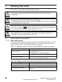
Running the motor .................................................................................... 54
8
SMARTCARD ............................................................................................. 66
2.1
2.2
2.3
3.1
3.2
3.3
3.4
3.5
3.6
3.7
3.8
3.9
4.1
4.2
4.3
4.4
4.5
4.6
4.7
4.8
5.1
5.2
5.3
5.4
5.5
5.6
5.7
5.8
5.9
5.10
5.11
7.1
7.2
8.1
Ratings ..................................................................................................................... 8
Nameplate description ........................................................................................... 10
Options / Accessories ............................................................................................ 12
Fire protection ........................................................................................................ 14
Mounting methods ................................................................................................. 16
Drive dimensions ................................................................................................... 17
Surface mounting .................................................................................................. 18
Through-panel mounting ....................................................................................... 19
Enclosure ............................................................................................................... 20
Fitting of IP54 insert .............................................................................................. 21
EMC filters ............................................................................................................. 22
Drive features ........................................................................................................ 25
Supply types .......................................................................................................... 27
Ratings ................................................................................................................... 27
Power connections ................................................................................................ 28
Braking resistor values (40°C [104°F]) .................................................................. 32
Encoder connections ............................................................................................. 33
Serial communications connections ...................................................................... 36
Shield connections ................................................................................................. 37
Control connections ............................................................................................... 39
Understanding the display ..................................................................................... 40
Keypad operation ................................................................................................... 41
Menu 0 ................................................................................................................... 43
Menu structure ....................................................................................................... 43
Advanced menus ................................................................................................... 44
Changing the operating mode ............................................................................... 45
Saving parameters ................................................................................................. 46
Restoring parameter defaults ................................................................................ 46
Displaying parameters with non-default values only .............................................. 47
Displaying destination parameters only ................................................................. 47
Parameter access level and security ..................................................................... 47
Quick start Connections ......................................................................................... 54
Quick Start / start-up ............................................................................................. 58
Introduction ............................................................................................................ 66
Unidrive SP Short Form Guide
Issue Number: 2
www.controltechniques.com
9
Advanced parameters ............................................................................... 69
10
11
Diagnostics .............................................................................................. 107
UL Listing Information ............................................................................ 119
9.1
9.2
9.3
9.4
9.5
9.6
9.7
9.8
9.9
9.10
9.11
9.12
9.13
9.14
9.15
9.16
9.17
9.18
Menu 1: Frequency / speed reference ...................................................................70
Menu 2: Ramps ......................................................................................................72
Menu 3: Frequency slaving, speed feedback and speed control ...........................74
Menu 4: Torque and current control .......................................................................78
Menu 5: Motor control ............................................................................................81
Menu 6: Sequencer and clock ................................................................................84
Menu 7: Analog I/O ................................................................................................85
Menu 8: Digital I/O .................................................................................................86
Menu 9: Programmable logic, motorized pot, binary sum and timers ....................88
Menu 10: Status and trips ......................................................................................90
Menu 11: General drive set-up ...............................................................................91
Menu 12: Threshold detectors, variable selectors and brake control function .......92
Menu 13: Position control .......................................................................................98
Menu 14: User PID controller ...............................................................................102
Menus 15, 16 & 17: Solutions Module set-up ......................................................104
Menu 18, 19 & 20: Application menu 1, 2 & 3 ......................................................105
Menu 21: Second motor parameters ....................................................................105
Menu 22: Additional Menu 0 set-up .....................................................................106
www.controltechniques.com
Unidrive SP Short Form Guide
Issue Number: 2
Safety Information
Safety
Information
1
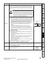
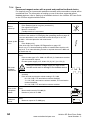
Warnings, Cautions and Notes
Product
Information
A Warning contains information which is essential for avoiding a safety hazard.
WARNING
CAUTION
A Note contains information, which helps to ensure correct operation of the product.
Electrical
Installation
NOTE
Electrical safety - general warning
Specific warnings are given at the relevant places in this User Guide.
System design and safety of personnel
The drive is intended as a component for professional incorporation into complete
equipment or a system. If installed incorrectly, the drive may present a safety hazard.
The drive uses high voltages and currents, carries a high level of stored electrical
energy, and is used to control equipment which can cause injury.
5
UL Listing
Information
www.controltechniques.com
Diagnostics
Careful consideration must be given to the functions of the drive which might result in a
hazard, either through their intended behaviour or through incorrect operation due to a
fault. In any application where a malfunction of the drive or its control system could lead
to or allow damage, loss or injury, a risk analysis must be carried out, and where
necessary, further measures taken to reduce the risk - for example, an over-speed
protection device in case of failure of the speed control, or a fail-safe mechanical brake
in case of loss of motor braking.
Advanced
parameters
With the sole exception of the SAFE TORQUE OFF function, none of the drive
functions must be used to ensure safety of personnel, i.e. they must not be used
for safety-related functions.
SMARTCARD
The STOP and SAFE TORQUE OFF functions of the drive do not isolate dangerous
voltages from the output of the drive or from any external option unit. The supply must
be disconnected by an approved electrical isolation device before gaining access to the
electrical connections.
Running the
motor
Close attention is required to the electrical installation and the system design to avoid
hazards either in normal operation or in the event of equipment malfunction. System
design, installation, commissioning / start-up and maintenance must be carried out by
personnel who have the necessary training and experience. They must read this safety
information and this User Guide carefully.
Getting Started Basic parameters
The voltages used in the drive can cause severe electrical shock and/or burns, and
could be lethal. Extreme care is necessary at all times when working with or adjacent to
the drive.
Unidrive SP Short Form Guide
Issue Number: 2
Mechanical
Installation
A Caution contains information which is necessary for avoiding a risk of damage to the
product or other equipment.
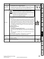
The SAFE TORQUE OFF function has been approved by BGIA as meeting the requirements
of the following standards, for the prevention of unexpected starting of the drive:
EN 61800-5-2:2007
SIL 3
EN ISO 13849-1:2006 PL e
EN 954-1:1997
Category 3
The SAFE TORQUE OFF function may be used in a safety-related application. The
system designer is responsible for ensuring that the complete system is safe and
designed correctly according to the relevant safety standards.
Environmental limits
Instructions in this User Guide regarding transport, storage, installation and use of the
drive must be complied with, including the specified environmental limits. Drives must
not be subjected to excessive physical force.
Access
Drive access must be restricted to authorized personnel only. Safety regulations which
apply at the place of use must be complied with.
Fire protection
The drive enclosure is not classified as a fire enclosure. A separate fire enclosure must
be provided. For further information, refer to section 3.1 Fire protection on page 14.
Compliance with regulations
The installer is responsible for complying with all relevant regulations, such as national
wiring regulations, accident prevention regulations and electromagnetic compatibility
(EMC) regulations. Particular attention must be given to the cross-sectional areas of
conductors, the selection of fuses or other protection, and protective ground (earth)
connections.
This User Guide contains instruction for achieving compliance with specific EMC
standards.
Within the European Union, all machinery in which this product is used must comply
with the following directives:
2006/42/EC: Safety of machinery.
2004/108/EC: Electromagnetic Compatibility.
Motor
Ensure the motor is installed in accordance with the manufacturer’s recommendations.
Ensure the motor shaft is not exposed.
Standard squirrel cage induction motors are designed for single speed operation. If it is
intended to use the capability of the drive to run a motor at speeds above its designed
maximum, it is strongly recommended that the manufacturer is consulted first.
Low speeds may cause the motor to overheat because the cooling fan becomes less
effective. The motor should be installed with a protection thermistor. If necessary, an
electric forced vent fan should be used.
The values of the motor parameters set in the drive affect the protection of the motor.
The default values in the drive should not be relied upon.
It is essential that the correct value is entered in parameter 0.46 motor rated current.
This affects the thermal protection of the motor.
6
www.controltechniques.com
Unidrive SP Short Form Guide
Issue Number: 2
Adjusting parameters
Electrical installation
The voltages present in the following locations can cause severe electric shock and may
be lethal:
Stored charge
The drive contains capacitors that remain charged to a potentially lethal voltage after the
AC supply has been disconnected. If the drive has been energized, the AC supply must
be isolated at least ten minutes before work may continue.
Getting Started Basic parameters
• AC supply cables and connections
• Output cables and connections
• Many internal parts of the drive, and external option units
Unless otherwise indicated, control terminals are single insulated and must not be
touched.
Electrical
Installation
Electric shock risk
Mechanical
Installation
Some parameters have a profound effect on the operation of the drive. They must not
be altered without careful consideration of the impact on the controlled system.
Measures must be taken to prevent unwanted changes due to error or tampering.
Product
Information
The brake control functions are provided to allow well co-ordinated operation of an
external brake with the drive. While both hardware and software are designed to high
standards of quality and robustness, they are not intended for use as safety functions,
i.e. where a fault or failure would result in a risk of injury. In any application where the
incorrect operation of the brake release mechanism could result in injury, independent
protection devices of proven integrity must also be incorporated.
Safety
Information
Mechanical brake control
Running the
motor
SMARTCARD
Advanced
parameters
Diagnostics
UL Listing
Information
Unidrive SP Short Form Guide
Issue Number: 2
www.controltechniques.com
7
2
Product Information
2.1
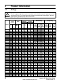
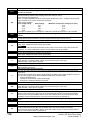
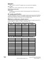
Ratings
WARNING
Fuses
The AC supply to the drive must be installed with suitable protection against overload
and short-circuits. The following section shows recommended fuse ratings. Failure to
observe this requirement will cause risk of fire.
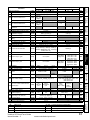
Table 2-1
Max. cont.
input
current
Model
SP0201
SP0202
SP0203
SP0204
SP0205
SP0401
SP0402
SP0403
SP0404
SP0405
SP1201
SP1202
SP1203
SP1204
SP1401
SP1402
SP1403
SP1404
SP1405
SP1406
SP2201
SP2202
SP2203
SP2401
SP2402
SP2403
SP2404
SP3201
SP3202
SP3401
SP3402
SP3403
SP3501
SP3502
SP3503
SP3504
SP3505
SP3506
SP3507
8
Size 0 to 3 ratings
Cable size
Fuse
Normal Duty
UL508C
Heavy Duty
Nom Motor
Nom Motor Max.
Max.
cont. power power cont. power power
UL Input Output Input Output output
@
@
output
@
@
230V
current 220V 230V current 220V
1ph
3ph
IEC
gG
A
A
A
A
6
10
12
16
20
4
4
6
6
8
10
12
20
20
8
8
8
12
12
16
20
25
32
20
25
32
32
50
63
40
50
63
8
10
12
16
20
25
32
10
10
16
20
20
10
10
10
10
10
10
15
20
20
8
8
10
15
15
15
20
25
30
20
25
30
30
45
60
40
45
60
10
10
15
15
20
25
30
5.0 3.6
7.6 5.6
9.6 6.9
13.5 8.9
17.4 12.3
2.3
2.8
3.3
4.4
5.7
9.5
11.3
16.4
19.1
4.8
5.8
7.4
10.6
11
13.4
18.1
22.6
28.3
17
21.4
27.6
27.6
43.1
54.3
36.2
42.7
53.5
6.7
8.2
11.1
14.4
18.1
22.2
26.0
EN60204
mm2 mm2 AWG AWG
0.75 0.75
16
24
1
0.75
16
22
1.5 0.75
14
20
2.5 0.75
12
18
4
0.75
12
18
0.75 0.75
16
24
0.75 0.75
16
24
0.75 0.75
16
24
0.75 0.75
16
22
0.75 0.75
16
20
1.5
1.0
14
18
1.5
1.0
14
16
4.0
1.0
12
14
4.0
1.5
12
14
1.0
1.0
16
22
1.0
1.0
16
20
1.0
1.0
16
18
1.5
1.0
14
16
1.5
1.0
14
14
2.5
1.5
14
14
4.0
2.5
12
14
4.0
4.0
10
10
6.0
6.0
8
8
4.0
2.5
12
14
4.0
4.0
10
10
6.0
6.0
8
8
6.0
6.0
8
8
16
16
6
6
25
25
4
4
10
10
6
6
16
16
6
6
25
25
4
4
1.0
1.0
16
18
1.0
1.0
16
16
1.5
1.0
14
14
2.5
1.5
14
14
4.0
2.5
12
14
4.0
4.0
10
10
6.0
6.0
8
8
A
kW
hp
5.2
6.8
9.6
11
2.8
3.8
5.0
6.9
8.8
11
15.5
22
28
15.3
21
29
1.1
1.5
2.2
3.0
1.1
1.5
2.2
3.0
4.0
5.5
4.0
5.5
7.5
7.5
11
15
1.5
2.0
3.0
3.0
1.5
2.0
3.0
5.0
5.0
7.5
5.0
7.5
10
10
15
20
42
54
35
43
56
5.4
6.1
8.4
11
16
22
27
11
15
18.5
22
30
3.0
4.0
5.5
7.5
11
15
18.5
15
20
25
30
40
3.0
5.0
7.5
10
15
20
25
www.controltechniques.com
A
kW
hp
2.2
3.1
4.0
5.7
7.5
1.3
1.7
2.1
3.0
4.2
4.3
5.8
7.5
10.6
2.1
3.0
4.2
5.8
7.6
9.5
12.6
17
25
13
16.5
25
29
31
42
32
40
46
4.1
5.4
6.1
9.5
12
18
22
0.37
0.55
0.75
1.1
1.5
0.37
0.55
0.75
1.1
1.5
0.75
1.1
1.5
2.2
0.75
1.1
1.5
2.2
3.0
4.0
3.0
4.0
5.5
5.5
7.5
11
15
7.5
11
15
18.5
22
2.2
3.0
4.0
5.5
7.5
11
15
0.5
0.75
1.0
1.5
2.0
0.5
0.75
1.0
1.5
2.0
1.0
1.5
2.0
3.0
1.0
1.5
2.0
3.0
5.0
5.0
3.0
5.0
7.5
10
10
20
20
10
15
25
30
30
2.0
3.0
5.0
7.5
10
15
20
Unidrive SP Short Form Guide
Issue Number: 2
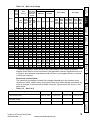
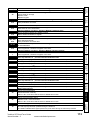
Table 2-2
3ph
Fuse option 2
semi. fuse in
series with
HRC fuse or
breaker
Cable size
EN60204
Normal Duty
UL508C
Heavy Duty
HRC
IEC
North
Max.
Nom Motor Max.
Nom Motor
class IEC
IEC America
cont. power power cont. power power
gG class Input Output Input Output
Class Ferraz
output
@
@
output
@
@
UL
aR
HSJ
current 220V 230V current 220V 230V
class
J
A
mm2
90
100
125
80
100
125
32
40
50
50
63
63
160
200
160
200
90
125
160
160
200
160
200
200
125
125
125
125
125
125
200
250
200
250
160
160
SP6401*
241
315
300
250
315
SP6402*
258
315
300
300
350
SP6601*
SP6602*
138
156
200
200
200
200
200
200
200
200
25
35
70
25
35
70
4
6
10
16
16
25
95
120
95
120
35
50
2x
70
2x
120
2 x 50
2 x 50
AWG
mm2 AWG
3
25
3
3
35
3
1
70
1
3
25
3
2
35
2
1
70
1
10
4
10
8
6
8
8
10
8
6
16
6
6
16
6
4
25
4
2/0
95
2/0
4/0
120
4/0
2/0
95
2/0
4/0
120
4/0
2
35
2
1
50
1
2x
2x
2x
2/0
70
2/0
2x
2x
2x
4/0
120
4/0
2 x 1 2 x 50 2 x 1
2 x 1 2 x 50 2 x 1
A
kW
hp
A
kW
hp
68
80
104
68
83
104
22
27
36
43
52
62
130
154
138
168
84
99
18.5
22
30
37
45
55
18.5
22
30
37
45
55
37
45
75
90
75
90
25
30
40
50
60
75
25
30
40
50
60
75
50
60
100
125
100
125
56
68
80
60
74
96
19
22
27
36
43
52
105
130
124
156
63
85
15
18.5
22
30
37
45
15
18.5
22
30
37
45
30
37
55
75
55
75
20
25
30
50
60
75
20
25
30
40
50
60
40
50
100
125
75
100
205
110
150
180
90
150
236
132
200
210
110
150
125
144
110
132
150
175
100
125
90
110
125
150
Operating mode
Advanced
parameters
Short term overload limits
The maximum percentage overload limit changes depending on the selected motor.
Variations in motor rated current, motor power factor and motor leakage inductance all
result in changes in the maximum possible overload. Typical values are shown in the
table below:
Table 2-3 Size 0 to 5
SMARTCARD
* Derating is applied to these drives at low output frequencies. Please contact the
supplier of the drive for more information if the application requires significant torque, at
or close to zero speed for extended periods of time or if prolonged periods of overload
(>100%) are required.
Running the
motor
A
90
100
125
80
110
125
60
60
60
60
60
60
175
225
175
225
100
100
Getting Started Basic parameters
A
100
100
125
80
110
125
63
63
63
63
63
80
200
250
200
250
125
125
Electrical
Installation
A
68.9
78.1
99.9
62.3
79.6
97.2
26.5
28.8
35.1
41
47.9
56.9
142
165
131
156
82.6
94.8
Mechanical
Installation
A
SP4201
SP4202
SP4203
SP4401
SP4402
SP4403
SP4601
SP4602
SP4603
SP4604
SP4605
SP4606
SP5201
SP5202
SP5401
SP5402*
SP5601
SP5602
Product
Information
Model
Fuse
option 1
Safety
Information
Max.
cont.
input
current
Size 4 to 6 ratings
CL from cold CL from 100% OL from cold OL from 100%
110% for 165s
110% for 9s
110% for 165s
110% for 9s
Heavy Duty overload with motor rated current =
drive rated current
175% for 40s
175% for 5s
150% for 60s
150% for 8s
Heavy Duty overload with a typical 4 pole motor 200% for 28s
200% for 3s
175% for 40s
175% for 5s
Diagnostics
Normal Duty overload with motor rated current
= drive rated current
UL Listing
Information
Unidrive SP Short Form Guide
Issue Number: 2
www.controltechniques.com
9
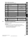
Table 2-4
Size 6
Operating mode
CL from cold CL from 100% OL from cold OL from 100%
Normal Duty overload with motor rated current
= drive rated current
110% for 165s
110% for 9s
110% for 165s
110% for 9s
Heavy Duty overload with motor rated current =
drive rated current
150% for 60s
150% for 8s
129% for 97s
129% for 15s
Generally the drive rated current is higher than the matching motor rated current
allowing a higher level of overload than the default setting as illustrated by the example
of a typical 4 pole motor.
The time allowed in the overload region is proportionally reduced at very low output
frequency on some drive ratings.
NOTE
2.2
The maximum overload level which can be attained is independent of the speed.
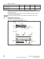
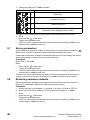
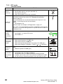
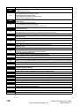
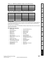
Nameplate description
See Figure 3-8 for location of rating labels.
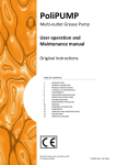
Figure 2-1
Typical drive rating labels for size 0
Rating label
Model
Input
voltage
Frequency Serial
number
S/N: 3000005001
I/P 200-240V 50-60Hz 1/3ph 13.5/7.9A
O/P 0-240V SPZ 2 M/TL 3ph 5.7/5.7A
Output voltage
range
Motor
output
Single/three
phase input current
Single/three phase
peak output current
Approvals label
Model
SP0204
Rating
1.1kW
Date code
Q26
Please read the manual before connecting
Electric Shock Risk: Wait 10 mins
between disconnecting supply
and accessing terminals
Serial
number
S/N: 3000005001
SPZ 2 M/TL
RoHS
Compliant
E171230
Designed in the U.K. Made in China
10
www.controltechniques.com
IND. CONTROL
EQUIPMENT
Approvals
R
Unidrive SP Short Form Guide
Issue Number: 2
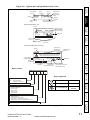
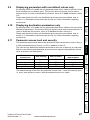
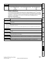
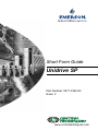
Figure 2-2
Typical drive rating labels for size 1 to 6
Safety
Information
Rating label (size 1 to 6)
Input voltage
rating
I/P 200-240V
50-60Hz
SP1201
3ph
Typical input
current for
Normal Duty
rating
7.1A
S.No: 3000005001
4.3 / 5.2A
SP 1,5 TL
Product
Information
Model
No. of
phases
Input
frequency
Serial
number
Heavy Duty / Normal Duty
rating output current
O/P 0-240V
Output voltage
range
Approvals label (Size 1 to 6)
Heavy Duty /
Normal Duty
power rating
Please read manual before connecting.
SP1201
0.75 / 1.1kW
Electric Shock Risk: Wait 10 min between
disconnecting supply & removing covers
IND.
CONT.
EQ.
1,5 TL
Approvals
R
SP
Electrical
Installation
Ser No: 3000005001
Serial
number
Mechanical
Installation
Model
Made In U.K
STDL25
Customer and
date code
Getting Started Basic parameters
Power stage label (Size 5 and 6 only)
Heavy Duty /
Normal Duty
power rating
Model
SP5402
75 / 90kW
Customer and
date code
STDN39
Please read manual before connecting.
Electric Shock Risk: Wait 10 min between
disconnecting supply & removing covers
Input voltage
Output voltage
Serial
number
I/P 380-480V
O/P 0-480V
50-60Hz 3ph 152.0A
156 / 168A
Ser No: 3000005001
E171230
Heavy Duty /
Normal Duty
rating output current
No. of phases &
Typical input current for
Normal Duty rating
Running the
motor
Input
frequency
Approvals
R
SP 100 T
Made In U.K
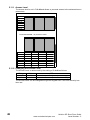
Model number
SP 6
4
0
1
SMARTCARD
Key to approvals
Unidrive product line
SP:
Solutions Platform
Complete inverter drive
CE approval
Voltage rating
0:
2:
4:
5:
6:
Voltage independent
200V to 240V
380V to 480V
500V to 575V
500V to 690V
C Tick approval
Australia
UL / cUL approval
USA &
Canada
R
Advanced
parameters
SP frame size
Europe
Diagnostics
Configuration
0:
1:
2:
3:
Wall mount drive
Free standing cubicle drive
Wall mount, no dynamic brake control
Free standing cubicle, no dynamic brake control
Current rating step
Unidrive SP Short Form Guide
Issue Number: 2
www.controltechniques.com
11
UL Listing
Information
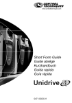
See section 3-8 Features of the size 0 to 6 drive on page 25 for location of rating labels.
Output current
The continuous output current ratings given on the rating label are for maximum 40°C
(104°F), 1000m altitude and 3.0 kHz switching. Derating is required for higher switching
frequencies, ambient temperatures >40°C (104°F) and higher altitude. For derating
information, refer to the Unidrive SP User Guide on the CD supplied with the drive.
Input current
The input current is affected by the supply voltage and impedance. The input current
given on the rating label is the typical input current and is stated for a balanced supply.
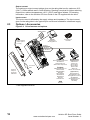
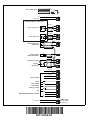
2.3
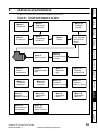
Options / Accessories
Figure 2-3
Drive features and options
SMARTCARD*
15-way D-type
converter
Keypad
SM-Keypad
SM-Keypad Plus
Internal braking
resistor (size 0
to 2 only)
SM slot 1
SM slot 2
SM slot 3
Feedback
SM-Universal Encoder Plus
SM-Resolver
SM-Encoder Plus
SM-Encoder Output Plus
CT Comms
cable
Fieldbus
SM-PROFIBUS-DP-V1
SM-DeviceNet
SM-INTERBUS
SM-CAN
SM-CANopen
SM-SERCOS
SM-Ethernet
SM-LON
SM-EtherCAT
External
footprint /
bookcase
EMC filter
SLM
Automation
(I/O Expansion)
SM-I/O Plus
SM-I/O Lite
SM-I/O Timer
SM-I/O PELV
SM-I/O 120V
SM-I/O 32
SM-I/O 24V Protected
(Applications)
SM-Applications
SM-Applications Lite
SM-Applications Lite V2
SM-EZMotion
SM-Applications Plus
SM-Register
SM-Safety
SM-SLM
* Part supplied with drive.
12
www.controltechniques.com
Unidrive SP Short Form Guide
Issue Number: 2
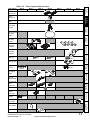
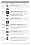
Table 2-5
Parts supplied with the drive
Size 0
Size 1
Size 2
Size 3
Size 4
Size 5
Size 6
Control
connectors
UL warning
label
Product
Information
Relay
connector
CAUTION
Risk of Electric Shock
Power down unit 10minutes
before removing cover
Mechanical
Installation
Grounding
bracket
Through panel
mounting
gasket
Electrical
Installation
Through panel
mounting
bracket
Getting Started Basic parameters
Surface
mounting
brackets
Top surface
mounting
brackets
Nylon
washers
M6
M6
M8
M6
Sealing clips
Running the
motor
Mounting
screws
M8x20
M4x10
SMARTCARD
Grounding
clamp
Ground
cable bridge
Advanced
parameters
DC terminal
cover
grommets
Ferrite ring
Diagnostics
Supply and
motor
connector
Ground fixing
screws
Safety
Information
Description
M6x12
Fan supply
connector
UL Listing
Information
IP54 gasket
IP54 insert
Unidrive SP Short Form Guide
Issue Number: 2
www.controltechniques.com
13
3
Mechanical Installation
Safety information
WARNING
WARNING
Follow the instructions
The mechanical and electrical installation instructions must be adhered to. Any
questions or doubt should be referred to the supplier of the equipment. It is the
responsibility of the owner or user to ensure that the installation of the drive and any
external option unit, and the way in which they are operated and maintained, comply with
the requirements of the Health and Safety at Work Act in the United Kingdom or
applicable legislation and regulations and codes of practice in the country in which the
equipment is used.
Stored charge
The drive contains capacitors that remain charged to a potentially lethal voltage after
the AC supply has been disconnected. If the drive has been energized, the AC supply
must be isolated at least ten minutes before work may continue.
Normally, the capacitors are discharged by an internal resistor. Under certain, unusual
fault conditions, it is possible that the capacitors may fail to discharge, or be prevented
from being discharged by a voltage applied to the output terminals. If the drive has failed
in a manner that causes the display to go blank immediately, it is possible the capacitors
will not be discharged. In this case, consult Control Techniques or their authorized
distributor.
WARNING
WARNING
Competence of the installer
The drive must be installed by professional assemblers who are familiar with the
requirements for safety and EMC. The assembler is responsible for ensuring that the
end product or system complies with all the relevant laws in the country where it is to be
used.
The weights of the size 4, 5 and 6 drives are as follows:
Size 4: 30 kg (66 lb)
Size 5: 55 kg (121 lb)
Size 6: 75 kg (165 lb)
Use appropriate safeguards when lifting these models
NOTE
3.1
When replacing the terminal covers the screws should be tightened with a maximum
torque of 1 N m (0.7 lb ft).
Fire protection
The drive enclosure is not classified as a fire enclosure. A separate fire enclosure must
be provided.
For installation in the USA, a NEMA 12 enclosure is suitable.
For installation outside the USA, the following (based on IEC 62109-1, standard for PV
inverters) is recommended.
Enclosure can be metal and/or polymeric, polymer must meet requirements which can
be summarized for larger enclosures as using materials meeting at least UL 94 class
5VB at the point of minimum thickness.
Air filter assemblies to be at least class V-2.
14
www.controltechniques.com
Unidrive SP Short Form Guide
Issue Number: 2
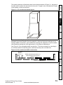
Figure 3-1 Fire enclosure bottom layout
Safety
Information
The location and size of the bottom shall cover the area shown in Figure 3-1. Any part of
the side which is within the area traced out by the 5° angle is also considered to be part
of the bottom of the fire enclosure.
Product
Information
Drive
Mechanical
Installation
Electrical
Installation
o
5
The bottom, including the part of the side considered to be part of the bottom, must be
designed to prevent escape of burning material - either by having no openings or by
having a baffle construction. This means that openings for cables etc. must be sealed
with materials meeting the 5VB requirement, or else have a baffle above.
Figure 3-2 Fire enclosure baffle construction
N o t le s s
th a n 2 X
SMARTCARD
Not less
than 2
times ‘X’
Running the
motor
See Figure 3-2 for acceptable baffle construction. This does not apply for mounting in
an enclosed electrical operating area (restricted access) with concrete floor.
Getting Started Basic parameters
o
5
Baffle plates (may be above or
below bottom of enclosure)
B a f f le p la t e s ( m a y b e
a b o v e o r b e lo w b o t t o m
o f e n c lo s u r e )
X
X
Advanced
parameters
B o t t o m o f fir e
e n c lo s u r e
Bottom of fire enclosure
Diagnostics
UL Listing
Information
Unidrive SP Short Form Guide
Issue Number: 2
www.controltechniques.com
15
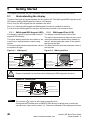
3.2
Mounting methods
Unidrive SP size 1 to 6 can be either surface or through-panel mounted using the
appropriate brackets. Size 0 can only be surface mounted.
WARNING
NOTE
If the drive has been used at high load levels for a period of time, the heatsink can reach
temperatures in excess of 70°C (158°F). Human contact with the heatsink should be
prevented.
In order to achieve IP54 rating (NEMA 12) for through-panel mounting, an IP54 insert must
be installed (size 1 and 2). See section 10.7 on page 109. Derating applies when the IP54
insert is installed. Additionally, the gasket provided should be installed between the drive
and the backplate to ensure a good seal for the enclosure. If the heatsink mounted braking
resistor is to be used with the drive through-panel mounted, refer to the Braking Resistor
Installation Sheet supplied with the resistor prior to mounting the drive. For further
information refer to the Unidrive SP User Guide on the CD Rom supplied with the drive.
Figure 3-3 New ingress protective label
Ingress protective labels
NOTE
16
The ingress protective labels (shown in Figure 3-3 above) should remain in place while the
drive is mounted, and until all the electrical wires have been connected. The labels should
be removed before first power up.
www.controltechniques.com
Unidrive SP Short Form Guide
Issue Number: 2
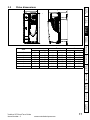
Drive dimensions
B
Safety
Information
3.3
C
Product
Information
Mechanical
Installation
A
Electrical
Installation
B
in
12.677
14.488
14.488
14.488
20.079
32.283
44.528
mm
62
100
155
250
310
310
310
C
in
2.441
3.937
6.102
9.843
12.205
12.205
12.205
mm
226
219
219
260
298
298
298
in
8.898
8.622
8.622
10.236
11.732
11.732
11.732
Running the
motor
0
1
2
3
4
5
6
A
mm
322
368
368
368
510
820
1131
Getting Started Basic parameters
Size
SMARTCARD
Advanced
parameters
Diagnostics
UL Listing
Information
Unidrive SP Short Form Guide
Issue Number: 2
www.controltechniques.com
17
3.4
Surface mounting
7.5mm
(0.295in)
40.0±5.0mm
(1.575±0.197in)
47mm
(1.850in)
106 ±1.0mm
4.173 ±0.039in
∅6.5mm
(0.256in)
∅6.5mm
(0.256in)
30.0mm
(1.181in)
24.5mm
(0.965in)
0
1
292mm
(11.496in)
∅5.4mm
(0.213in)
370.0±1.0mm
(14.567±0.039in)
6mm
(0.236in)
106±1.0mm
(4.173±0.039in)
2
∅6.5mm
(0.256in)
337.5 ±1.0mm
(13.287 ±0.039in)
∅6.5mm
(0.256in)
258.6±0.5mm
(10.181±0.020in)
∅6.5mm
(0.256in)
∅8.5mm
(0.335in)
25.7±0.5mm
(1.012±0.020in)
97mm
(3.819in)
47mm
(1.850in)
3
327±1.0mm
(12.874±0.039in)
∅6.5mm
(0.256in)
18
4
528.8±0.5mm
(20.819±0.020in)
5
839.3±0.5mm
(33.043±0.020in)
6
1150.8±0.5mm
(45.307±0.020in)
∅8.5mm
(0.335in)
www.controltechniques.com
Unidrive SP Short Form Guide
Issue Number: 2
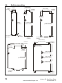
Through-panel mounting
Safety
Information
3.5
70 ±0.3mm
(2.756 ±0.012in)
70.0±0.3mm
(2.756±0.012in)
93.0±0.5mm
(3.661±0.020in)
35.0 ±0.15mm
(1.378 ±0.006in)
(0.256in)
∅6.5mm
(0.256in)
Product
Information
35.0±0.15mm
(1.378±0.006in)
∅ 6.5mm
64.6± 0.5mm
15.6±0.5mm
(2.543 ±0.020in)
(0.614±0.020in)
148 ±0.5mm
(5.827 ±0.020in)
Mechanical
Installation
368.0±1.0mm
(14.488±0.039in)
343.0±0.5mm
(13.504±0.020in)
368.0 ±1.0mm
(14.488 ±0.039in)
294 ±0.5mm
(11.575 ±0.020in)
(0.256in)
9.3 ±0.5mm
(0.366 ±0.020in)
9.4±0.75mm
(0.370±0.030in)
101.5 ±0.5mm
(3.996 ±0.020in)
∅6.5mm
(0.256in)
∅6.5mm
(0.256in)
258.6±0.5mm
(10.181±0.020in)
26.65±0.5mm
1.049±0.020in)
56±0.5mm
(2.205±0.020in)
3
4
487.0±0.5mm
(19.173±0.020in)
4
540.3±0.5mm
(21.272±0.020in)
5
797.5±0.5mm
(31.938±0.020in)
5
825.6±0.5mm
(33.567±0.020in)
6
1107.8±0.5mm
(43.614±0.020in)
6
1161.2±0.5mm
(45.717±0.020in)
R6.5mm
(0.256in)
∅6.5mm
(0.256in)
258.6±0.5mm
(10.181±0.020in)
Diagnostics
14.2±0.5mm
0.559±0.020in)
∅8.5mm
(0.335in)
www.controltechniques.com
19
UL Listing
Information
Size 1 to 3 only: When the drive is through-panel mounted, the main terminal cover(s)
must be removed in order to provide access to the mounting holes.
Unidrive SP Short Form Guide
Issue Number: 2
Advanced
parameters
8 ±0.3mm
(0.315 ±0.012in)
R6.5mm
(0.256in)
SMARTCARD
287±0.5mm
(11.299±0.020in)
∅8.5mm
(0.335in)
Running the
motor
286.0±0.5mm
(11.260±0.020in)
236±0.5mm
(9.291±0.020in)
Getting Started Basic parameters
∅ 6.5mm
2
Electrical
Installation
1
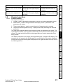
3.6
Enclosure
Enclosure Layout
Please observe the clearances in the diagram below taking into account any
appropriate notes for other devices / auxiliary equipment when planning the installation.
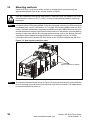
Figure 3-4 Enclosure layout
Optional braking resistor and overload
Locate optional braking
resistor and overload
external to cubicle
(preferably near to or
on top of the cubicle).
Enclosure
AC supply
contactor and
fuses or MCB
≥100mm
(4in)
Ensure minimum clearances
are maintained for the drive
and external EMC filter. Forced
or convection air-flow must not
be restricted by any object or
cabling
A Size 0 and 1: ≥0mm (0in)
Size 2 to 6: ≥30mm (1.181in)
A
A
The external EMC filter can be
bookcase mounted (next to the
drive) or footprint mounted (with
the drive mounted onto the filter).
External
controller
≥100mm
(4in)
Note
For EMC compliance:
1) When using an external EMC
filter, one filter is required for
each drive
2) Power cabling must be at
least 100mm (4in) from the
drive in all directions
3) Ensure direct metal contact
at drive and filter mounting
points (any paint must be
removed)
Signal cables
Plan for all signal cables
to be routed at least
300mm (12in) from the
drive and any power cable
20
www.controltechniques.com
Unidrive SP Short Form Guide
Issue Number: 2
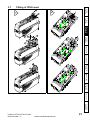
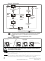
Fitting of IP54 insert
3
1
1
2
Safety
Information
3.7
3
2
2
1
Product
Information
1
Mechanical
Installation
4
4
Electrical
Installation
5
5
6
7
Getting Started Basic parameters
Running the
motor
8
6
9
SMARTCARD
Advanced
parameters
4. The IP54 insert can be found in the accessories box.
Diagnostics
6. The gasket can be found in the accessories box.
UL Listing
Information
Unidrive SP Short Form Guide
Issue Number: 2
www.controltechniques.com
21
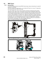
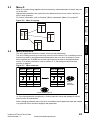
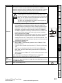
3.8
3.8.1
EMC filters
Internal filter
It is recommended that the internal EMC filter be kept in place unless there is a specific
reason for removing it.
If the drive is part of a regen system or is a Unidrive SP size 3 to 6 on an IT supply then
the internal EMC filter must be removed.
The internal EMC filter reduces radio-frequency emission into the line power supply.
Where the motor cable is short, it permits the requirements of EN61800-3:2004 to be
met for the second environment - for further information see the Unidrive SP User Guide
on the CD Rom supplied with the drive. For longer motor cables the filter continues to
provide a useful reduction in emission level, and when used with any length of shielded
motor cable up to the limit for the drive, it is unlikely that nearby industrial equipment will
be disturbed. It is recommended that the filter be used in all applications unless the
ground leakage current (on 400V, 50Hz supply) of 28mA for sizes 0 to 3 and 56mA for
sizes 4 to 6 is unacceptable or the above conditions are true.
Figure 3-5 Removal of Size 0 internal EMC filter
2
Figure 3-6 Removal of Size 1 to 3 internal EMC filters
1
2
3
4
22
www.controltechniques.com
Unidrive SP Short Form Guide
Issue Number: 2
Figure 3-7 Removal of Size 4 to 6 internal EMC filters
Safety
Information
1
Product
Information
2
Mechanical
Installation
Electrical
Installation
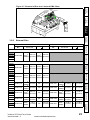
3.8.2
External filter
Epcos
L1, L2, L3
No.
Getting Started Basic parameters
Schaffner
No.
L1, L2, L3
1 ph
SP0201
SP0202
2
0.8 N m 4mm2 0.8 N m
SP0203 4200-6000 4mm
12AWG (0.6 lb ft) 12AWG (0.6 lb ft)
SP0204
SP0205
3 ph
0.8 N m 4mm2 0.8 N m
4mm2
12AWG (0.6 lb ft) 12AWG (0.6 lb ft)
4200-6002
0.8 N m 4mm2 0.8 N m
4mm2
12AWG (0.6 lb ft) 12AWG (0.6 lb ft)
M5
M5
2
3.5 N m
0.6 N m
4200-6121 4mm
(2.6 lb ft)
12AWG (0.4 lb ft)
2
3.5 N m
0.6 N m
4200-6120 4mm
(2.6 lb ft)
12AWG (0.4 lb ft)
M5
3.0 N m
(2.2 lb ft)
M5
3.0 N m
(2.2 lb ft)
M5
2
3.5 N m
0.6 N m
4200-6121 4mm
(2.6 lb ft)
12AWG (0.4 lb ft)
M5
3.0 N m
(2.2 lb ft)
4200-6119
4mm2 0.8 N m
12AWG (0.6 lb ft)
M5
2
3.5 N m
0.6 N m
4200-6120 4mm
(2.6 lb ft)
12AWG (0.4 lb ft)
M5
3.0 N m
(2.2 lb ft)
4200-6210
2Nm
10mm2
8AWG (1.5 lb ft)
M5
2 1.35 N m
3.5 N m
4200-6211 10mm
(2.6 lb ft)
8AWG (1.0 lb ft)
M5
3.0 N m
(2.2 lb ft)
Unidrive SP Short Form Guide
Issue Number: 2
www.controltechniques.com
23
UL Listing
Information
4mm2 0.8 N m
12AWG (0.6 lb ft)
Diagnostics
4200-6118
Advanced
parameters
4mm2 0.8 N m
12AWG (0.6 lb ft)
2
0.8 N m
4200-6119 4mm
12AWG (0.6 lb ft)
4200-6118
SMARTCARD
4200-6001
Running the
motor
SP0201
SP0202
SP0203
SP0204
SP0205
SP0401
SP0402
SP0403
SP0404
SP0405
SP1201
SP1202
SP1203
SP1204
SP1401
SP1402
SP1403
SP1404
SP1405
SP1406
SP2201
SP2202
SP2203
Schaffner
No.
SP2401
SP2402
SP2403
SP2404
SP3201
SP3202
SP3401
SP3402
SP3403
SP3501
SP3502
SP3503
SP3504
SP3505
SP3506
SP3507
SP4201
SP4202
SP4203
SP4401
SP4402
SP4403
SP4601
SP4602
SP4603
SP4604
SP4605
SP4606
SP5201
SP5202
SP5401
SP5402
SP5601
SP5602
SP6401
SP6402
SP6601
SP6602
Epcos
L1, L2, L3
No.
L1, L2, L3
4200-6210
10mm2
8AWG
2Nm
(1.5 lb ft)
M5
2 1.35 N m
3.5 N m
4200-6211 10mm
(2.6 lb ft)
8AWG (1.0 lb ft)
M5
3.0 N m
(2.2 lb ft)
4200-6307
16mm2
6AWG
2.2 N m
(1.6 lb ft)
M6
2
3.9 N m
4200-6306 16mm
(2.9 lb ft)
6AWG
2.2 N m
(1.6 lb ft)
M6
5.1 N m
(3.8 lb ft)
4200-6305
16mm2
6AWG
2.2 N m
(1.6 lb ft)
M6
2
3.9 N m
4200-6306 16mm
(2.9 lb ft)
6AWG
2.2 N m
(1.6 lb ft)
M6
5.1 N m
(3.8 lb ft)
4200-6309
16mm2
6AWG
2.2 N m
(1.6 lb ft)
M6
2
3.9 N m
4200-6308 16mm
(2.9 lb ft)
6AWG
2.2 N m
(1.6 lb ft)
M6
5.1 N m
(3.8 lb ft)
4200-6406
50mm2
0AWG
8Nm
(5.9 lb ft)
M10
2
25 N m
4200-6405 50mm
(18.4 lb ft)
0AWG
6.8 N m
10 N m
M10
(5.0 lb ft)
(7.4 lb ft)
4200-6408
25mm2
4AWG
2.3 N m
(1.7 lb ft)
M6
2
3.9 N m
4200-6407 50mm
(2.9 lb ft)
0AWG
6.8 N m
10 N m
M10
(5.0 lb ft)
(7.4 lb ft)
4200-6503
95mm2 20 N m
4/0AWG (14.7 lb ft)
M10
4200-6504
50mm2
0AWG
M10
8Nm
(5.9 lb ft)
4200-6603
M10
4200-6604
M10
2
25 N m
20 N m
10 N m
4200-6501 95mm
M10
(18.4 lb ft)
(7.4 lb ft)
4/0AWG (14.7 lb ft)
2
25 N m
20 N m
10 N m
4200-6502 95mm
M10
(18.4 lb ft)
(7.4 lb ft)
4/0AWG (14.7 lb ft)
25 N m
10 N m
4200-6601
M10
(18.4 lb ft)
(7.4 lb ft)
25 N m
10 N m
4200-6602
M10
(18.4 lb ft)
(7.4 lb ft)
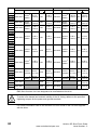
The external EMC filters for sizes 0 to 3 can be footprint or bookcase mounted. The external
EMC filters for sizes 4 to 6 are designed to be mounted above the drive.
To avoid a fire hazard and maintain validity of the UL listing, adhere to the specified
tightening torques for the power and ground terminals.
WARNING
For further information refer to the Unidrive SP User Guide on the CD Rom supplied
with the drive.
24
www.controltechniques.com
Unidrive SP Short Form Guide
Issue Number: 2
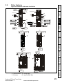
Drive features
Safety
Information
3.9
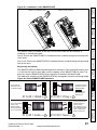
Figure 3-8 Features of the size 0 to 6 drive
M6
4Nm
M3.5
1Nm
LED
A
SMARTCARD
SM 2
1
LED
A
0
8
Product
Information
SMARTCARD
1
B
8
SM 1
1-6
SM 2
2.5mm
4Nm
21
SM 1
11
31
3mm
4Nm
5
10
15
B
31
42
41
3mm
4Nm
Electrical
Installation
8mm
4Nm
8mm
4Nm
M6
4Nm
2.5mm
4Nm
21
1
6
11
42
41
11
1
C
Mechanical
Installation
SM 3
1
M3.5
1Nm
DC
DC
Pozi Pz 2
/ 6.5mm
1.5Nm
T20 / 6.5mm
1.5Nm
T20 / 6.5mm
1.5Nm
D
D
1
2
AC
Pozi Pz 2
/ 6.5mm
1.5Nm
SMARTCARD
Pozi Pz 2
/ 6.5mm
1.5Nm
Running the
motor
AC
Pozi Pz 2
/ 6.5mm
1.5Nm
DC
Pozi Pz 3
/ 10mm
2.5Nm
Getting Started Basic parameters
Pozi Pz 2
/ 6.5mm
1.5Nm
M10 nut
17mm AF
T20 / 6.5mm
1.5Nm
D
3
Advanced
parameters
D
456
Diagnostics
AC
Pozi Pz 3
/ 10mm
2.5Nm
A. Serial comms
B. Rating label
C. Encoder
D. Internal EMC filter
Unidrive SP Short Form Guide
Issue Number: 2
www.controltechniques.com
2.5mm
UL Listing
Information
M10 nut
17mm AF
25
4
Electrical Installation
Electric shock risk
The voltages present in the following locations can cause severe electric shock and
may be lethal:
WARNING
WARNING
WARNING
WARNING
WARNING
WARNING
WARNING
26
• AC supply cables and connections
• DC and brake cables, and connections
• Output cables and connections
• Many internal parts of the drive, and external option units
Unless otherwise indicated, control terminals are single insulated and must not be touched.
Isolation device
The AC supply must be disconnected from the drive using an approved isolation device
before any cover is removed from the drive or before any servicing work is performed.
STOP function
The STOP function does not remove dangerous voltages from the drive, the motor or any
external option units.
SAFE TORQUE OFF function
The SAFE TORQUE OFF function does not remove dangerous voltages from the drive,
the motor or any external option units.
Stored charge
The drive contains capacitors that remain charged to a potentially lethal voltage after the
AC supply has been disconnected. If the drive has been energized, the AC supply must
be isolated at least ten minutes before work may continue.
Normally, the capacitors are discharged by an internal resistor. Under certain, unusual fault
conditions, it is possible that the capacitors may fail to discharge, or be prevented from being
discharged by a voltage applied to the output terminals. If the drive has failed in a manner
that causes the display to go blank immediately, it is possible the capacitors will not be
discharged. In this case, consult Control Techniques or their authorized distributor.
Equipment supplied by plug and socket
Special attention must be given if the drive is installed in equipment which is connected
to the AC supply by a plug and socket. The AC supply terminals of the drive are
connected to the internal capacitors through rectifier diodes which are not intended to
give safety isolation. If the plug terminals can be touched when the plug is disconnected
from the socket, a means of automatically isolating the plug from the drive must be used
(e.g. a latching relay).
Permanent magnet motors
Permanent magnet motors generate electrical power if they are rotated, even when the
supply to the drive is disconnected. If that happens then the drive will become energized
through its motor terminals.
If the motor load is capable of rotating the motor when the supply is disconnected, then
the motor must be isolated from the drive before gaining access to any live parts.
www.controltechniques.com
Unidrive SP Short Form Guide
Issue Number: 2
Supply types
Safety
Information
4.1
All drives are suitable for use on any supply type i.e TN-S, TN-C-S, TT and IT.
Supplies with voltage up to 600V may have grounding at any potential, i.e. neutral,
centre or corner (“grounded delta”)
Drives are suitable for use on supplies of installation category III and lower, according to
IEC60664-1. This means they may be connected permanently to the supply at its origin
in a building, but for outdoor installation additional over-voltage suppression (transient
voltage surge suppression) must be provided to reduce category IV to category III.
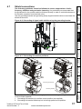
4.2
If the drive is to be used on an IT (ungrounded) supply, refer to the Unidrive SP User
Guide for more information.
Mechanical
Installation
NOTE
Product
Information
Supplies with voltage above 600V may not have corner grounding
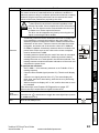
Ratings
Electrical
Installation
NOTE
The recommended output cable sizes in section 2.1 Ratings on page 8 assume that the
motor maximum current matches that of the drive. Where a motor of reduced rating is
used the cable rating may be chosen to match that of the motor. To ensure that the motor
and cable are protected against over-load, the drive must be programmed with the
correct motor rated current.
Running the
motor
NOTE
UL listing is dependent on the use of the correct type of UL-listed fuse, and applies when
symmetrical short-circuit current does not exceed 5kA for sizes 1 to 3.
SMARTCARD
Advanced
parameters
WARNING
Fuses
The AC supply to the drive must be installed with suitable protection against overload
and short-circuits. section 2.1 Ratings on page 8 shows recommended fuse ratings.
Failure to observe this requirement will cause risk of fire.
Getting Started Basic parameters
See section 2.1 Ratings on page 8.
Maximum continuous input current
The values of maximum continuous input current are given to aid the selection of cables
and fuses. These values are stated for the worst case condition with the unusual
combination of stiff supply with high imbalance. The value stated for the maximum
continuous input current would only be seen in one of the input phases. The current in
the other two phases would be significantly lower.
The values of maximum input current are stated for a supply with a 2% negative phasesequence imbalance and rated at the maximum supply fault current given in section
2.1 Ratings on page 8.
The recommended cable sizes in section 2.1 Ratings on page 8 are only a guide. Refer
to local wiring regulations for the correct size of cables. In some cases a larger cable is
required to avoid excessive voltage drop.
A fuse or other protection must be included in all live connections to the AC supply.
•
•
See Chapter 11 UL Listing Information on page 119 for UL listing requirements.
Fuse Types
The fuse voltage rating must be suitable for the drive supply voltage.
Unidrive SP Short Form Guide
Issue Number: 2
www.controltechniques.com
27
UL Listing
Information
The fault-clearing capacity must be sufficient for the installation
For frame sizes 2 and 3, the drive must be mounted in an enclosure which meets
the requirements for a fire enclosure
Diagnostics
An MCB (miniature circuit breaker) or MCCB (moulded-case circuit-breaker) with type C
may be used in place of fuses for size 1 to 3 under the following conditions:
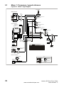
4.3
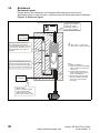
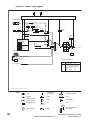
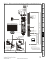
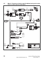
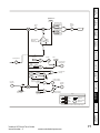
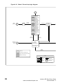
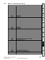
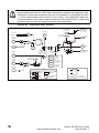
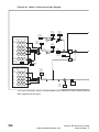
Power connections
Figure 4-1 Size 0 power connections
SP020X = 200 to 240V±10%
SP040X = 380 to 480V±10%
Connectors specification:
Maximum size of power cable
= 4.0mm2(10AWG)
Torque setting = 1 N m
Supply
ground
Mains
supply
L1*
L2*
L3*
Fuses
Optional
line reactor
Optional EMC
filter
Low voltage
DC (48V)
+
_
1
PE
L1
L2
L3
AC
connections
U
V
W
1
DC
_
DC
+
High current
-DC connections
NOTE
28
* When using a 200V drive on a single phase supply, the live and neutral conductors can
be connected to any of the AC connections on the drive.
** This is not required if the optional internal braking resistor is used.
1. Maximum torque for ground terminal connections = 4N m (2.95 Ib ft).
www.controltechniques.com
Unidrive SP Short Form Guide
Issue Number: 2
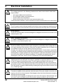
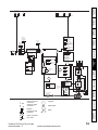
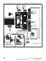
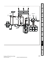
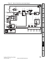
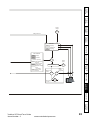
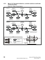
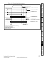
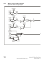
Figure 4-2 Size 1 to 3 power connections
Safety
Information
1
23
-DC
+DC
Optional
braking
resistor
DC1 DC2
BR
BR
48V
-DC
+DC
DC1 = - DC2 = +
Internal
EMC filter
High current DC and braking
Mechanical
Installation
48V
Product
Information
Optional
braking
resistor
Low current DC and 48V
Internal
EMC filter
Electrical
Installation
DC
2
Getting Started Basic parameters
3
1
1
PE
L1
L2
L3
U
V
W
Running the
motor
AC
23
L1
L2
L3
PE
U
V
W
SMARTCARD
Optional EMC filter
Optional EMC filter
Optional line reactor
Optional line reactor
Advanced
parameters
L2
L3
L1
L2
Diagnostics
L1
L3
Unidrive SP Short Form Guide
Issue Number: 2
www.controltechniques.com
29
UL Listing
Information
On Unidrive SP size 2 and 3, the high current DC connections must always be used
when using a braking resistor, supplying the drive from DC (low voltage DC or high
voltage DC) or using the drive in a parallel DC bus system. The low current DC
connection is used to connect low voltage DC to the drive internal power supply and to
connect the internal EMC filter.
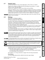
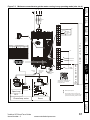
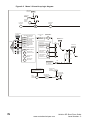
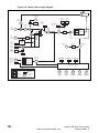
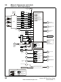
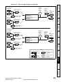
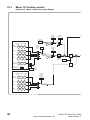
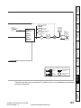
Figure 4-3 Size 4 to 6 power connections
L1
L2
L3
Optional line reactor
Optional EMC filter
L1
PE
L2
L3
+DC
-DC
Internal
EMC filter
456
6
U
V
W
+DC
30
Heatsink fan supply connections
BR
www.controltechniques.com
Unidrive SP Short Form Guide
Issue Number: 2
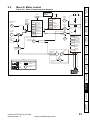
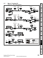
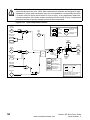
Ground connections
1
2
Running the
motor
0
Getting Started Basic parameters
Supply
ground
Electrical
Installation
Figure 4-4 Ground connections
Mechanical
Installation
WARNING
The ground loop impedance must conform to the requirements of local safety regulations.
The drive must be grounded by a connection capable of carrying the prospective fault
current until the protective device (fuse, etc.) disconnects the AC supply.
The ground connections must be inspected and tested at appropriate intervals.
Product
Information
The drive must be connected to the system ground of the AC supply. The ground wiring
must conform to local regulations and codes of practice.
On size 0, the supply and motor ground connections are made using the M6 threaded
hole in the metal back plate of the drive located at the top and bottom of the drive.
On size 1, the supply and motor ground connections are made using the M5 studs
located either side of the drive near the plug-in power connector.
On size 2, the supply and motor ground connections are made using the grounding
bridge that locates at the bottom of the drive.
On size 3, the supply and motor ground connections are made using a M6 nut and bolt
that locates in the fork protruding from the heatsink between the AC supply and motor
output terminals.
On size 4 to 6, the supply and motor ground connections are made using M10 studs
located at the top and bottom of the drive near the input and output power connections.
See Figure 4-4 for details.
Safety
Information
WARNING
Electrochemical corrosion of earthing terminals
Ensure that grounding terminals are protected against corrosion i.e. as could be caused
by condensation.
SMARTCARD
Motor
ground
3
Advanced
parameters
Supply
ground
Plain washers
Spring washer
456
Diagnostics
M6 bolt
UL Listing
Information
Motor
ground
Unidrive SP Short Form Guide
Issue Number: 2
www.controltechniques.com
31
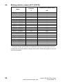
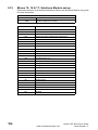
4.4
Braking resistor values (40°C [104°F])
Model
Minimum
resistance*
Instantaneous power rating
Ω
kW
SP0201 ~ SP0205
35
4.35
SP0401 ~ SP0405
105
5.79
SP1201 ~ SP1203
43
3.5
SP1204
29
5.3
SP1401 ~ SP1404
74
8.3
SP1405 ~ SP1406
58
10.6
SP2201 - SP2203
18
8.9
SP2401 ~ SP2404
19
33.1
SP3201 ~ SP3202
5.0
30.3
SP3401 ~ SP3403
18
35.5
SP3501 ~ SP3507
18
50.7
SP4201 ~ SP4203**
5.0
30.3
SP4401 ~ SP4402**
11
55.3
SP4403**
9
67.6
SP4601 ~ SP4606**
13
95.0
SP5201 ~ SP5202**
3.5
53
SP5401 ~ SP5402**
7
86.9
SP5601 ~ SP5602**
10
125
SP6401 ~ SP6402**
5
122
SP6601 ~ SP6602**
10
125
* Resistor tolerance: ±10%.
** The power ratings specified are for a stand-alone drive only. If the drive is part of a
common DC bus system different ratings must be used. Contact the supplier of the drive
for more information.
32
www.controltechniques.com
Unidrive SP Short Form Guide
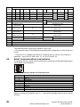
Issue Number: 2
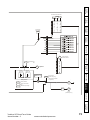
Encoder connections
Safety
Information
4.5
Figure 4-5 Encoder
1
6
11
5
10
15
Product
Information
4.5.1 Location of encoder connector (size 0)
Mechanical
Installation
Before using the encoder connector on size 0 for the first time, the break-out need
removing as shown in Figure 4-6.
Figure 4-6 Access to encoder connections
Running the
motor
NOTE
After removing the break-out, ensure that the ground tab is connected to ground. This
will connect 0V of the drive to ground. This is required to enable the drive to meet IP20
when the break-out is removed.
Getting Started Basic parameters
WARNING
Electrical
Installation
Break-outs
Do not remove the break-out if the encoder connection is not required.
Figure 4-7 Location of encoder connector (size 0)
SMARTCARD
1
6
11
Drive encoder connector
Female 15-way D-type
Diagnostics
Encoder
input
Advanced
parameters
5
10
15
UL Listing
Information
Unidrive SP Short Form Guide
Issue Number: 2
www.controltechniques.com
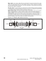
33
Figure 4-8 Connecting the encoder ground tab to the EMC bracket
NOTE
The size of the connecting cable between the encoder ground tab and the EMC bracket
should be equal to the input cable.
4.5.2
Location of encoder connector (size 1 to 6)
Figure 4-9 Location of encoder connector
5
10
15
1
6
11
Drive encoder connector
Female 15-way D-type
34
www.controltechniques.com
Unidrive SP Short Form Guide
Issue Number: 2
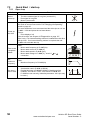
Encoder types
Safety
Information
4.5.3
Table 4-1 Encoder types
Setting of
Pr 3.38
Absolute SinCos encoder with HiperFace serial communications
protocol (Stegmann)
Absolute EndAt serial communications encoder (Heidenhain)
Absolute SinCos encoder with EnDat serial communications protocol
(Heidenhain)
Absolute SSI only encoder
SMARTCARD
* This feedback device provides very low resolution feedback and should not be used
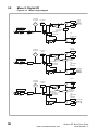
for applications requiring a high level of performance
** The U, V & W commutation signals are required with an incremental type encoder
when used with a servo motor. The UVW commutation signals are used to define the
motor position during the first 120° electrical rotation after the drive is powered-up or the
encoder is initialized.
Running the
motor
Absolute SinCos encoder with SSI
Getting Started Basic parameters
SinCos encoder without serial communications
Electrical
Installation
Fd.SErVO
(4)
Fr.SErVO
(5)
SC
(6)
SC.HiPEr
(7)
EndAt
(8)
SC.EndAt
(9)
SSI
(10)
SC.SSI
(11)
Incremental encoder with frequency pulses and direction, with or
without marker pulse
Incremental encoder with forward pulses and reverse pulses, with or
without marker pulse
Quadrature incremental encoder with UVW commutation signals, with
or without marker pulse
Encoder with UVW commutation signals only (Pr 3.34 set to zero)*
Incremental encoder with frequency pulses and direction
with commutation signals**, with or without marker pulse
Incremental encoder with forward pulses and reverse pulses with
commutation signals**, with or without marker pulse
Mechanical
Installation
Ab.SErVO
(3)
Quadrature incremental encoder with or without marker pulse
Product
Information
Ab
(0)
Fd
(1)
Fr
(2)
Description
Advanced
parameters
Diagnostics
UL Listing
Information
Unidrive SP Short Form Guide
Issue Number: 2
www.controltechniques.com
35
Pr 3.38
Term
Ab
(0)
Fd
(1)
Fr Ab.SErVO Fd.SErVO Fr.SErVO SC SC.HiPEr EndAt SC.EndAt SSI SC.SSI
(2)
(3)
(4)
(5)
(6)
(7)
(8)
(9)
(10)
(11)
1
2
3
4
5
6
A
A\
B
B\
F
F\
D
D\
F
F\
R
R\
7
8
9
10
A
A\
B
B\
Z*
Z\*
F
F\
D
D\
Simulated encoder
Aout, Fout**
Simulated encoder
Aout\, Fout\**
Simulated encoder
Bout, Dout**
Simulated encoder
Bout\, Dout\**
U
U\
V
V\
11
12
13
14
15
W
W\
F
F\
R
R\
Cos
Cos
Cos
Cosref
Cosref
Cosref
Sin
Sin
Sin
Sinref
Sinref
Sinref
Encoder input - Data (input/output)
Encoder input - Data\ (input/output)
Simulated encoder
Aout, Fout**
Simulated encoder
Aout\, Fout\**
Simulated encoder
Bout, Dout**
Simulated encoder
Bout\, Dout\**
Encoder input - Clock (output)
Encoder input - Clock\ (output)
+V***
0V common
th****
*Marker pulse is optional.
**Simulated encoder output only available in open-loop.
***The encoder supply is selectable through parameter configuration to 5Vdc, 8Vdc and
15Vdc.
****Terminal 15 is a parallel connection to T8 analog input 3. If this is to be used as a
thermistor input, set Pr 7.15 to ‘th.sc’ (7), ‘th’ (8) or ‘th.diSP’ (9).
4.6
Serial communications connections
The Unidrive SP has a serial communications port (serial port) as standard supporting 2
wire EIA485 communications.
1
8
Table 4-2 Connection details for RJ45 connector
Pin
1
2
3
4
5
6
7
8
Shell
Function
120Ω Termination resistor
RX TX
0V isolated
+24V (100 mA)
0V isolated
TX enable
RX\ TX\
RX\ TX\ (if termination resistors are required, link to pin 1)
0V isolated
The communications port applies a 2 unit load to the communications network.
Minimum number of connections are 2, 3, 7 and shield. Shielded cable must be used at
all times.
36
www.controltechniques.com
Unidrive SP Short Form Guide
Issue Number: 2
Shield connections
Product
Information
The following guidelines should be followed to ensure suppression of radiofrequency emission and good noise immunity. It is particularly recommended that
the guidelines for the encoder cable be followed closely in order to avoid disturbance to
the encoder operation from electrical noise.
Use the grounding bracket and grounding clamp supplied with the drive to terminate the
shields at the drive.
Figure 4-10 Grounding of signal cable shields using the grounding bracket
Safety
Information
4.7
Mechanical
Installation
Electrical
Installation
Getting Started Basic parameters
Figure 4-11 Grounding link bracket positions
Running the
motor
SMARTCARD
2
1
Advanced
parameters
Grounding link bracket
Diagnostics
Mounting bracket
Unidrive SP Short Form Guide
Issue Number: 2
www.controltechniques.com
37
UL Listing
Information
When a Unidrive SP size 4 or 5 is through-panel mounted, the grounding link bracket
must be folded upwards.
1. Grounding link bracket in its surface mount position (as supplied)
2. Grounding link bracket folded up into its through-panel mount position
Motor cable: use a motor cable with an overall shield. Connect the shield of the motor
cable to the ground terminal of the motor frame using a link that is as short as possible
and not exceeding 50mm (2in) long. A full 360° termination of the shield to the terminal
housing of the motor is beneficial.
Encoder cable: for best shielding use cable with an overall shield and individual shields
on twisted pairs, connect the cable as illustrated in Figure 4-12. Clamp the overall shield
to grounded metallic surfaces at both the encoder and the drive.
Brake resistor cable: the optional braking resistor should also be wired with shielded
cable. If unshielded wire is required refer to Unidrive SP User Guide for guidance.
Control cables: if the control wiring is to leave the enclosure, it must be shielded and
the shield(s) clamped to the drive using the grounding bracket. Remove the outer
insulating cover of the cable to ensure the shield(s) make contact with the bracket, but
keep the shield(s) intact until as close as possible to the terminals.
Figure 4-12 Feedback cable shield connections
Shield
connection
to 0V
Twisted
pair
shield
Cable
Twisted
pair
shield
Connection
at motor
Connection
at drive
Cable
shield
38
Shield
connection
to 0V
Ground clamp
on shield
www.controltechniques.com
Cable
shield
Unidrive SP Short Form Guide
Issue Number: 2
Control connections
Safety
Information
4.8
Figure 4-13 Default terminal functions
1
11
Polarised signal
connectors
41 42
Product
Information
21
31
1
0V
2
+24V input
3
0V
5
Non-inverting input
6
Inverting input
Single-ended
signal
Mechanical
Installation
Analog frequency/speed
reference 1
Electrical
Installation
0V
Non-inverting input
Differential signal
Inverting input
Analog input 3
(Motor thermistor)
Torque (active
current)
+10V output
7
Analog input 2
8
Analog input 3
Analog output 1
Analog output 2
11
0V
21
0V
+24V output
(user selectable)
22
23
0V
At zero speed
24
Digital I/O 1
Digital I/O 2
26
Digital I/O 3
Run reverse
Analog input 1/
input 2 select
27
Digital input 4
28
Digital input 5
29
Digital input 6
30
0V
31
Drive enable (SAFE
TORQUE OFF function)*
Analog input 1
Analog input 2
Jog forward select
41
42
Relay (Overvoltage
category II)
UL Listing
Information
Drive ok
Diagnostics
25
Advanced
parameters
Reset
Run forward
SMARTCARD
9
10
Running the
motor
Speed / frequency
4
Getting Started Basic parameters
Analog
frequency/speed
reference 2
*The SAFE TORQUE OFF / Drive enable terminal is a positive logic input only.
NOTE
Avoid connecting digital and analog grounds (T21 and T11).
Unidrive SP Short Form Guide
Issue Number: 2
www.controltechniques.com
39
5
Getting Started
This chapter introduces the user interfaces, menu structure and security level of the drive.
5.1
Understanding the display
There are two types of keypad available for the Unidrive SP. The SM-Keypad/SP0 Keypad has an
LED display and the SM-Keypad Plus has an LCD display.
Size 0: Only the SP0 Keypad can be installed to the drive.
Size 1 to 6: Both the SM-Keypad and SM-Keypad Plus can be installed to the drive.
For all sizes the SM-Keypad Plus can also be remotely mounted on an enclosure door.
5.1.1
SM-Keypad/SP0 Keypad (LED)
5.1.2
SM-Keypad Plus (LCD)
The display consists of two horizontal rows of 7 The display consists of three lines of text.
segment LED displays.
The top line shows the drive status or the current
The upper display shows the drive status or the menu and parameter number being viewed on
current menu and parameter number being
the left, and the parameter value or the specific
viewed.
trip type on the right.
The lower display shows the parameter value or The lower two lines show the parameter name or
the specific trip type.
the help text.
Figure 5-1
SM-Keypad
Figure 5-2
SM-Keypad Plus
Upper display
Lower display
Mode (black) button
Help button
Mode (black) button
Control buttons
Fwd / Rev (blue) button
Stop/reset (red) button
Start (green) button
Joypad
Control buttons
Fwd / Rev (blue) button
Stop/reset (red) button
Start (green) button
Joypad
Beware of possible live terminals when attaching the SP0 Keypad to the drive.
WARNING
Figure 5-3
SP0 Keypad
Upper display
NOTE
Lower display
Navigation keys
Start (green) button
Mode (black) button
Fwd / Rev (blue) button
Stop/reset (red) button
The red stop
button is also used to reset the drive.
All keypads can indicate when a SMARTCARD access is taking place or when the
second motor map is active (menu 21). These are indicated on the displays as follows.
40
www.controltechniques.com
Unidrive SP Short Form Guide
Issue Number: 2
SM-Keypad Plus
Second motor map active
The decimal point after the
third digit in the upper display
will flash.
5.2
Keypad operation
Control buttons
The display examples in this section show the SM-Keypad 7 segment LED display. The
examples are the same for the SM-Keypad Plus except that the information displayed
on the lower row on the SM-Keypad is displayed on the right hand side of the top row on
the SM-Keypad Plus.
Getting Started Basic parameters
The Help button toggles between other display modes and parameter help mode. The
up and down functions on the joypad scroll the help text to allow the whole string to be
viewed. The right and left functions on the joypad have no function when help text is
being viewed.
Electrical
Installation
The keypad consists of:
1. Joypad - used to navigate the parameter structure and change parameter values.
2. Mode button - used to change between the display modes – parameter view,
parameter edit, status.
3. Three control buttons - used to control the drive if keypad mode is selected.
4. Help button (SM-Keypad Plus only) - displays text briefly describing the selected
parameter.
Mechanical
Installation
5.2.1
The symbol ‘Mot2’ will appear
in the lower left hand corner of
the display
Product
Information
SMARTCARD access taking
place
Safety
Information
SM-Keypad / SP0 Keypad
The symbol ‘CC’ will appear in
The decimal point after the
fourth digit in the upper display the lower left hand corner of
the display
will flash.
Running the
motor
SMARTCARD
Advanced
parameters
Diagnostics
UL Listing
Information
Unidrive SP Short Form Guide
Issue Number: 2
www.controltechniques.com
41
Figure 5-4
Display modes
Status
Mode
(Display
not
flashing)
To enter Parameter
Mode, press
key or
Timeout**
Timeout**
To return to
Status Mode,
press
key
Parameter
Mode
(Upper
display
flashing)
When returning
to Parameter
Mode use the
*
Use
Temporary
Parameter
Mode
(Upper display
flashing)
keys to select
another parameter
to change, if
required
* keys
to select parameter for editing
To exit Edit Mode,
press
key
To enter Edit Mode,
press
key
RO
parameter
Timeout**
R/W
parameter
Edit Mode
(Character to be edited in lower line of display flashing)
Change parameter values using
keys.
* Can only be used to move between menus if L2 access has been enabled
(Pr 0.49). Refer to section 5.11 Parameter access level and security on
page 47.
**Timeout defined by Pr 11.41 (default value = 240s).
Figure 5-5
Mode examples
Parameter
View Mode
Status Mode
Healthy Status
Alarm Status
Trip Status
Drive status = tripped
Trip type (UV = undervolts)
Menu 5. Parameter 5
Pr 5.05 value
Do not change parameter values without careful consideration; incorrect values may
cause damage or a safety hazard.
WARNING
NOTE
When changing the values of parameters, make a note of the new values in case they
need to be entered again.
NOTE
For new parameter-values to apply after the AC supply to the drive is interrupted, new
values must be saved. Refer to section 5.7 Saving parameters on page 46.
42
www.controltechniques.com
Unidrive SP Short Form Guide
Issue Number: 2
Menu 0
Figure 5-6
Menu 0 copying
Menu 2
Mechanical
Installation
2.21
5
Menu 0
0.04
0.05
0.06
Menu 1
5
0
150
Electrical
Installation
1.14
0
Menu 4
5.4
150
Menu structure
The drive parameter structure consists of menus and parameters.
The drive initially powers up so that only menu 0 can be viewed. The up and down arrow
buttons are used to navigate between parameters and once level 2 access (L2) has
been enabled (see Pr 0.49) the left and right buttons are used to navigate between
menus. For further information, refer to section 5.11 Parameter access level and
security on page 47.
Running the
motor
Figure 5-7
Menu structure
Menu 2
Menu 21 Menu 22
Pr 1.00
Pr 1.01
Pr 1.02
Pr 2.00
Pr 2.01
Pr 2.02
Pr 21.00
Pr 21.01
Pr 21.02
Pr 22.00
Pr 22.01
Pr 22.02
Pr 0.48
Pr 0.49
Pr 0.50
Pr 1.49
Pr 1.50
Pr 1.51
Pr 2.36
Pr 2.37
Pr 2.38
Pr 21.29
Pr 21.30
Pr 21.31
Pr 22.27
Pr 22.28
Pr 22.29
Moves
between
parameters
Advanced
parameters
Menu 1
Pr 0.00
Pr 0.01
Pr 0.02
SMARTCARD
Menu 0
43
UL Listing
Information
www.controltechniques.com
Diagnostics
Moves between Menus
The menus and parameters roll over in both directions.
i.e. if the last parameter is displayed, a further press will cause the display to rollover
and show the first parameter.
When changing between menus the drive remembers which parameter was last viewed
in a particular menu and thus displays that parameter.
Unidrive SP Short Form Guide
Issue Number: 2
Getting Started Basic parameters
4.07
Product
Information
Menu 0 is used to bring together various commonly used parameters for basic easy set
up of the drive.
Appropriate parameters are copied from the advanced menus into menu 0 and thus
exist in both locations.
For further information, refer to Chapter 6 Basic parameters (Menu 0) on page 50.
Safety
Information
5.3
5.5
Advanced menus
The advanced menus consist of groups or parameters appropriate to a specific function
or feature of the drive. Menus 0 to 22 can be viewed on both keypads. Menus 40 and 41
are specific to the SM-Keypad Plus (LCD). Menus 70 to 91 can be viewed with an SMKeypad Plus (LCD) only when an SM-Applications is installed.
Menu
Description
LED
LCD
0
Commonly used basic set up parameters for quick / easy programming
9
9
1
Frequency / speed reference
9
9
2
Ramps
9
9
3
Slave frequency, speed feedback and speed control
9
9
4
Torque and current control
9
9
5
Motor control
9
9
6
Sequencer and clock
9
9
7
Analog I/O
9
9
8
Digital I/O
9
9
9
Programmable logic, motorized pot and binary sum
9
9
10
Status and trips
9
9
11
General drive set-up
9
9
12
Threshold detectors and variable selectors
9
9
13
Position control
9
9
14
User PID controller
9
9
9
9
15, 16, 17 Solutions Module set-up
44
18
Application menu 1
9
9
19
Application menu 2
9
9
20
Application menu 3
9
9
21
Second motor parameters
9
9
22
Additional Menu 0 set-up
9
9
40
Keypad configuration menu
X
9
41
User filter menu
X
9
70
PLC registers
X
9
71
PLC registers
X
9
72
PLC registers
X
9
73
PLC registers
X
9
74
PLC registers
X
9
75
PLC registers
X
9
85
Timer function parameters
X
9
86
Digital I/O parameters
X
9
88
Status parameters
X
9
90
General parameters
X
9
91
Fast access parameters
X
9
www.controltechniques.com
Unidrive SP Short Form Guide
Issue Number: 2
SM-Keypad Plus set-up menus
Menu 40 parameter descriptions
Parameter
Parameter 0
40.01
Language selection
40.04
40.06
40.07
LCD contrast
Drive and attribute database upload was
bypassed
Browsing favourites control
Keypad security code
40.08
Communication channel selection
40.09
40.10
40.11
40.19
40.20
40.21
40.22
Hardware key code
Drive node ID (Address)
Flash ROM memory size
String database version number
Screen saver strings and enable
Screen saver interval
Turbo browse time interval
40.05
Table 5-2
Parameter 0
Range(Ú)
0 to 32767
Browsing filter source F01 to F50
Pr 0.00 to Pr 391.51
Browsing favourites control
Normal (0), Filter (1)
Changing the operating mode
Procedure
Use the following procedure only if a different operating mode is required:
Advanced
parameters
1. Ensure the drive is not enabled, i.e. terminal 31 is open or Pr 6.15 is OFF (0)
2. Enter either of the following values in Pr 0.00, as appropriate:
1253 (Europe, 50Hz AC supply frequency)
1254 (USA, 60Hz AC supply frequency)
SMARTCARD
Changing the operating mode returns all parameters to their default value, including the
motor parameters. (Pr 0.49 Security status and Pr 0.34 User security code are not
affected by this procedure.)
Running the
motor
5.6
Normal (0), Filter (1)
0 to 999
Disable (0), Slot1 (1), Slot2 (2),
Slot3 (3), Slave (4), Direct (5)
0 to 999
0 to 255
4Mbit (0), 8Mbit (1)
0 to 999999
None (0), Default (1), User (2)
0 to 600
0 to 200ms
Menu 41 parameter descriptions
Parameter
41.00
41.01 to
41.50
41.51
Updated (0), Bypass (1)
Getting Started Basic parameters
Save to flash
Electrical
Installation
Software version
40.03
0 to 32767
English (0), Custom (1), French (2),
German (3), Spanish (4), Italian (5)
999999
Idle (0), Save (1), Restore (2),
Default (3)
0 to 31
Mechanical
Installation
40.02
Range(Ú)
Product
Information
40.00
Safety
Information
Table 5-1
Diagnostics
UL Listing
Information
Unidrive SP Short Form Guide
Issue Number: 2
www.controltechniques.com
45
3. Change the setting of Pr 0.48 as follows:
Pr 0.48 setting
Operating mode
1
Open-loop
2
Closed-loop Vector
3
Closed-loop Servo
4
Regen (See the Unidrive SP Regen User Guide for more
information about operating in this mode)
The figures in the second column apply when serial communications are used.
4.
•
•
•
5.7
Either:
Press the red
reset button
Toggle the reset digital input
Carry out a drive reset through serial communications by setting Pr 10.38 to 100
(ensure that Pr. xx.00 returns to 0).
Saving parameters
When changing a parameter in Menu 0, the new value is saved when pressing the
Mode button to return to parameter view mode from parameter edit mode.
If parameters have been changed in the advanced menus, then the change will not be
saved automatically. A save function must be carried out.
Procedure
Enter 1000* in Pr. xx.00
Either:
• Press the red
reset button
• Toggle the reset digital input
• Carry out a drive reset through serial communications by setting Pr 10.38 to 100
(ensure that Pr. xx.00 returns to 0).
*If the drive is in the under voltage trip state or is being supplied from a 48V back-up
supply, a value of 1001 must be entered into Pr xx.00 to perform a save function.
5.8
Restoring parameter defaults
Restoring parameter defaults by this method saves the default values in the drive’s
memory. (Pr 0.49 and Pr 0.34 are not affected by this procedure.)
Procedure
1. Ensure the drive is not enabled, i.e. terminal 31 is open or Pr 6.15 is OFF (0)
2. Enter 1233 (EUR 50Hz settings) or 1244 (USA 60Hz settings) in Pr xx.00.
3. Either:
•
•
•
46
Press the red
reset button
Toggle the reset digital input
Carry out a drive reset through serial communications by setting Pr 10.38 to 100
(ensure that Pr. xx.00 returns to 0).
www.controltechniques.com
Unidrive SP Short Form Guide
Issue Number: 2
Please note that this function can be affected by the access level enabled, refer to
section 5.11 Parameter access level and security for further information regarding
access level.
Product
Information
5.10
Displaying parameters with non-default values only
By entering 12000 in Pr xx.00, the only parameters that will be visible to the user will be
those containing a non-default value. This function does not require a drive reset to
become active. In order to deactivate this function, return to Pr xx.00 and enter a value
of 0.
Safety
Information
5.9
Displaying destination parameters only
5.11
Parameter access level and security
The user security determines whether the access to the user is read only or read write.
Both the user security and parameter access level can operate independently of each
other as shown in the table below:
Advanced
menus status
Not visible
Not visible
RW
RO
The default settings of the drive are parameter access level L1 and user security open,
i.e. read / write access to menu 0 with the advanced menus not visible.
Running the
motor
Parameter
User security
Menu 0 status
access level
L1
Open
RW
L1
Closed
RO
L2
Open
RW
L2
Closed
RO
RW = Read / write access
RO = Read only access
Getting Started Basic parameters
The parameter access level determines whether the user has access to menu 0 only or
to all the advanced menus (menus 1 to 22) in addition to menu 0.
Electrical
Installation
Please note that this function can be affected by the access level enabled, refer to
section 5.11 Parameter access level and security for further information regarding
access level.
Mechanical
Installation
By entering 12001 in Pr xx.00, the only parameters that will be visible to the user will be
destination parameters. This function does not require a drive reset to become active. In
order to deactivate this function, return to Pr xx.00 and enter a value of 0.
SMARTCARD
Advanced
parameters
Diagnostics
UL Listing
Information
Unidrive SP Short Form Guide
Issue Number: 2
www.controltechniques.com
47
5.11.1 Access Level
The access level is set in Pr 0.49 and allows or prevents access to the advanced menu
parameters.
L1 access selected - Menu 0 only visible
Pr 0.00
Pr 0.01
Pr 0.02
Pr 0.03
Pr 1.00
Pr 1.01
Pr 1.02
Pr 1.03
Pr 0.49
Pr 0.50
Pr 1.49
Pr 1.50
............
............
............
............
............
............
............
............
Pr 19.00
Pr 19.01
Pr 19.02
Pr 19.03
Pr 20.00
Pr 20.01
Pr 20.02
Pr 20.03
Pr 19.49
Pr 19.50
Pr 20.49
Pr 20.50
L2 access selected - All parameters visible
Pr 0.00
Pr 0.01
Pr 0.02
Pr 0.03
Pr 1.00
Pr 1.01
Pr 1.02
Pr 1.03
Pr 0.49
Pr 0.50
Pr 1.49
Pr 1.50
............
............
............
............
............
............
............
............
Pr 21.00
Pr 21.01
Pr 21.02
Pr 21.03
Pr 22.00
Pr 22.01
Pr 22.02
Pr 22.03
Pr 21.30
Pr 21.31
Pr 22.28
Pr 22.29
5.11.2 Changing the Access Level
The Access Level is determined by the setting of Pr 0.49 as follows:
String
L1
L2
Value
0
1
Effect
Access to menu 0 only
Access to all menus (menu 0 to menu 22)
The Access Level can be changed through the keypad even if the User Security has
been set.
48
www.controltechniques.com
Unidrive SP Short Form Guide
Issue Number: 2
5.11.3 User Security
User security open - All parameters: Read / Write access
Safety
Information
The User Security, when set, prevents write access to any of the parameters (other than
Pr. 0.49 and Pr 11.44 Access Level) in any menu.
Product
Information
Pr 0.49
Pr 0.50
Pr 1.49
Pr 1.50
............
............
............
............
............
............
............
............
Pr 21.00
Pr 21.01
Pr 21.02
Pr 21.03
Pr 22.00
Pr 22.01
Pr 22.02
Pr 22.03
Pr 21.30
Pr 21.31
Pr 22.28
Pr 22.29
Electrical
Installation
Pr 1.00
Pr 1.01
Pr 1.02
Pr 1.03
Mechanical
Installation
Pr 0.00
Pr 0.01
Pr 0.02
Pr 0.03
Getting Started Basic parameters
User security closed - All parameters: Read Only access
(except Pr 0.49 and Pr 11.44)
Pr 0.00
Pr 0.01
Pr 0.02
Pr 0.03
Pr 1.00
Pr 1.01
Pr 1.02
Pr 1.03
Pr 0.49
Pr 0.50
Pr 1.49
Pr 1.50
............
............
............
............
............
............
............
............
Pr 21.00
Pr 21.01
Pr 21.02
Pr 21.03
Pr 22.00
Pr 22.01
Pr 22.02
Pr 22.03
Pr 21.30
Pr 21.31
Pr 22.28
Pr 22.29
Unlocking User Security
button, the upper display
will now show CodE. Use the arrow buttons to set the security code and press the
button.
If an incorrect security code is entered the display will revert to parameter view mode.
To lock the User Security again, set Pr 0.49 to Loc and press the
reset button.
Diagnostics
With the correct security code entered, the display will revert to the parameter selected
in edit mode.
Advanced
parameters
Select a read write parameter to be edited and press the
SMARTCARD
Enter a value between 1 and 999 in Pr 0.34 and press the
button; the security code
has now been set to this value. In order to activate the security, the Access level must
be set to Loc in Pr 0.49. When the drive is reset, the security code will have been
activated and the drive returns to Access Level L1. The value of Pr 0.34 will return to 0
in order to hide the security code. At this point, the only parameter that can be changed
by the user is the Access Level Pr 0.49.
Running the
motor
Setting User Security
Disabling User Security
the
button. The User Security has now been disabled, and will not have to be
unlocked each time the drive is powered up to allow read / write access to the
parameters.
Unidrive SP Short Form Guide
Issue Number: 2
www.controltechniques.com
49
UL Listing
Information
Unlock the previously set security code as detailed above. Set Pr 0.34 to 0 and press
6
Basic parameters (Menu 0)
Range(Ú)
Parameter
OL
0.00 xx.00
{x.00}
0.01 Minimum reference clamp
{1.07}
0.02 Maximum reference clamp
0.03 Acceleration rate
0.04 Deceleration rate
{1.06}
{2.11}
{2.21}
0.05 Reference select
{1.14}
0.06 Current limit
{4.07}
0.07
0.08
0.09
0.10
OL> Voltage mode select
{5.14}
CL> Speed controller P gain
{3.10}
OL> Voltage boost
{5.15}
CL> Speed controller I gain
{3.11}
OL> Dynamic V/F
{5.13}
CL> Speed controller D gain
{3.12}
OL> Estimated motor speed
{5.04}
CL> Motor speed
OL & VT> Drive output
frequency
{3.02}
{5.01}
0.11
SV> Drive encoder position
{3.29}
0.12 Total motor current
OL & VT> Motor active current
0.13
SV> Analog input 1 offset trim
0.14 Torque mode selector
{4.01}
{4.02}
{7.07}
{4.11}
0.15 Ramp mode select
{2.04}
OL> T28 and T29 auto-selection
{8.39}
0.16 disable
CL> Ramp enable
{2.02}
OL> T29 digital input destination {8.26}
0.17
CL> Current demand filter time
constant
0.18 Positive logic select
{8.29}
0.19 Analog input 2 mode
{7.11}
0.20 Analog input 2 destination
{7.14}
0.21 Analog input 3 mode
{7.15}
0.22 Bipolar reference select
{1.10}
50
{4.12}
VT
SV
0 to 32,767
±SPEED_LIMIT_MAX
±3,000.0Hz
Hz/rpm
Default(Ö)
OL
SV
RW
0.0
RW
EUR>
1,500.0
USA>
1800.0
3,000.0
RW
5.0
2.000
0.200
RW
10.0
2.000
0.200
RW
0 to 3,000.0 SPEED_LIMIT_MAX Hz/ EUR> 50.0
Hz
rpm
USA> 60.0
0.0 to
0.000 to 3,200.000
3,200.0
s/1,000rpm
s/100Hz
0.0 to
0.000 to 3,200.000
3,200.0
s/1,000rpm
s/100Hz
A1.A2 (0), A1.Pr (1), A2.Pr (2), Pr (3),
Pad (4), Prc (5)
0 to Current_limit_max %
Ur_S (0),
Ur (1),
Fd (2),
Ur_Auto (3),
Ur_I (4),
SrE (5)
Type
VT
0
A1.A2 (0)
165.0
RW
175.0
RW
Ur_I (4)
0.0000 to 6.5535 1/rad s-1
RW
0.0300
0.0100
Size 0 to 2:
3.0
Size 4 & 5:
2.0
Size 6: 1.0
0.0 to
25.0% of
motor rated
voltage
0.00 to 655.35 1/rad
OFF (0) or
On (1)
RW
RW
0.10
1.00
0
RW
RW
0.00000 to 0.65535 (s)
0.00000
±180,000
rpm
RW
RO
±Speed_max rpm
RO
±Speed_freq_max Hz
0 to 65,535
1/216ths of
a revolution
0 to Drive_current_max A
±Drive_current_max A
±10.000 %
0 to 1
0 to 4
FASt (0)
FASt (0)
Std (1)
Std (1)
Std.hV (2)
OFF (0) or
On (1)
OFF (0) or On (1)
Pr 0.00 to
Pr 21.51
RO
RO
0.000
Speed control mode (0)
Std (1)
www.controltechniques.com
RW
0
RW
On (1)
Pr 6.31
RW
RW
0.0 to 25.0 ms
OFF (0) or On (1)
0-20 (0), 20-0 (1), 4-20tr (2), 204tr (3), 4-20 (4), 20-4 (5), VOLt (6)
Pr 0.00 to Pr 21.51
0-20 (0), 20-0 (1), 4-20tr (2), 204tr (3), 4-20 (4), 20-4 (5), VOLt (6),
th.SC (7), th (8), th.diSp (9)
OFF (0) or On (1)
RO
RO
RW
RW
0.0
On (1)
RW
RW
th (8)
RW
Pr 1.37
RW
VOLt (6)
RW
OFF (0)
RW
Unidrive SP Short Form Guide
Issue Number: 2
Range(Ú)
0.23 Jog reference
0.24 Pre-set reference 1
0.25 Pre-set reference 2
{1.05}
{1.21}
{1.22}
OL> Pre-set reference 3
{1.23}
CL> Overspeed threshold
{3.08}
OL> Pre-set reference 4
{1.24}
0.27
0.30 Parameter copying
0.37 Serial comms address
0
RW
0 to 50,000
1024
0.40 Autotune
0.41 Maximum switching frequency
0.42 No. of motor poles
OL & VT> Motor rated power
factor
0.43
SV> Encoder phase angle
{5.12}
{5.18}
{5.11}
0 to 2
0 to 4
0 to 6
3 (0), 4 (1), 6 (2), 8 (3), 12 (4), 16 (5) kHz
0 to 60 (Auto to 120 pole)
0.000 to 1.000
{11.31}
0.49 Security status
0.50 Software version
0.51 Action on trip detection
{11.44}
{11.29}
{10.37}
RW
RW
RW
RW
RW
RW
RW
0.0
200V drive: 230
400V drive: EUR> 400, USA> 460
0 to AC_voltage_set_max V
575V drive: 575
690V drive: 690
EUR>
0 to
0.00 to
EUR>
1,450.00
180,000
40,000.00
1,500
USA>
rpm
rpm
USA> 1,800
1,770.00
0.0 to 400.0
20.0
0 to Rated_current_max A
Drive rated current [11.32]
0 to 3,000.0 0 to 1,250.0
EUR> 50.0
Hz
Hz
USA> 60.0
OPEn LP (1), CL VECt (2),
OPEn LP
CL VECt (2) SErVO (3)
SErVO (3), rEgEn (4)
(1)
L1 (0), L2 (1), Loc (2)
1.00 to 99.99
0 to 15
0
RW
RW
RW
RW
RW
RW
RW
RW
RO
RW
Diagnostics
0.48 Operating mode selector
1
200V drive: 75
400V drive: 150
575V drive: 180
690V drive: 215
200V drive: 1000
All voltage
400V drive: 2000
ratings 40
575V drive: 2400
690V drive: 3000
0
3 (0)
6 (2)
0 (Auto)
6 POLE (3)
Advanced
parameters
{5.06}
RW
0.850
0.0 to
359.9°
0.47 Rated frequency
19200 (6)
SMARTCARD
0 to 30,000
SV> Motor thermal time constant {4.15}
0.46 Motor rated current
{5.07}
0
0
rtU (1)
RW
RW
RW
RW
Running the
motor
{4.14}
{5.08}
RO
Basic
parameters
0.39 Current loop I gain
OL & VT> Motor rated full load
0.45 speed (rpm)
RW
All voltage
ratings: 20
0 to 30,000
{5.09}
nonE (0)
0
{4.13}
0.44 Motor rated voltage
RW
RW
RO
RO
0 to 3
0.38 Current loop P gain
{3.25}
4096
OFF (0)
0
0.00 to 9999.99A
0 to 2
0 to 999
AnSI (0), rtu (1), Lcd (2)
300 (0), 600 (1), 1200 (2), 2400 (3),
4800 (4), 9600 (5), 19200 (6), 38400 (7),
{11.25}
57600 (8) Modbus RTU only, 115200 (9)
Modbus RTU only
{11.23}
0 to 247
{5.10}
RW
0.0
Getting Started
0.36 Serial comms baud rate
RW
OFF (0) or On (1)
0 to 999
nonE (0), rEAd (1), Prog (2),
{11.42}
AutO (3), boot (4)
{11.33} 200 (0), 400 (1), 575 (2), 690 (3) V
{6.09}
{5.16}
{11.30}
{11.24}
RW
RW
RW
0.0
{6.13}
{11.36}
{11.32}
SV
Electrical
Installation
0.31 Drive rated voltage
Maximum Heavy Duty current
0.32
rating
OL> Catch a spinning motor
0.33
VT> Rated rpm autotune
0.34 User security code
0.35 Serial comms mode
{3.34}
Type
VT
0.0
0.0
0.0
Mechanical
Installation
CL> Drive encoder lines per
revolution
0.28 Keypad fwd/rev key enable
0.29 SMARTCARD parameter data
OL
Product
Information
0.26
Default(Ö)
OL
VT
SV
0 to 400.0 Hz
0 to 4000.0 rpm
±Speed_limit_max rpm
±Speed_limit_max rpm
±Speed_
freq_max
Hz/rpm
0 to 40,000 rpm
±Speed_
freq_max
Hz/rpm
Safety
Information
Parameter
Key:
Open loop
Closed loop vector and Servo
Closed loop vector
Servo
Unidrive SP Short Form Guide
Issue Number: 2
UL Listing
Information
OL
CL
VT
SV
{X.XX} Copied advanced parameter
RW
Read/write: can be written by the user
RO
Read only: can only be read by the user
www.controltechniques.com
51
Figure 6-1
Menu 0 logic diagram
28
29
The function of the two digital inputs are controlled by the setting of Pr 0.05 (reference selector). See table below for details.
Analog reference
5
6
Analog input 2
offset trim
0.13
Analog input
2 mode
Analog input 2
destination
Any
unprotected
variable
parameter
0.20
+
??.??
+
0.19
7
Analog
reference 2
1.37
0.05
??.??
Reference
selector
OR
Bipolar
reference
select
0.22
Preset frequency
reference
0.24
Preset
frequency 1
0.25
Preset
frequency 2
A1.A2
0.27
0
A1.Pr 1
A2.Pr
Open Loop only
Preset
0.26
frequency 3
2
Pr
PAd
Preset
frequency 4
Prc
3
4
5
Keypad reference
0.23
Jog reference
M
0.28
Enable forward /
reverse key
Digital inputs T28 & T29
Pr 0.05
A1.A2
A1.Pr
A2.Pr
Pr
PAd
Prc
Preset reference
T28
T29
Local/Remote
Jog
Preset reference selectors
Preset reference selectors
Preset reference selectors
Local/Remote
Jog
Local/Remote
Jog
The parameters are all shown in their default settings
Key:
Input
Connected to
ground / off
Summing junction
Output
Invert
Limit
AND
Comparator
Input or output
programmable
&
0.XX
RW parameter
OR
0.XX
RO parameter
NOR
OR
Sum
Σ
X.XX
52
NOR
www.controltechniques.com
Selector controlled
by Pr x.xx
Unidrive SP Short Form Guide
Issue Number: 2
26
OL> FREQUENCY
CL> SPEED
RESET
27
25
TORQUE
9
Safety
Information
RUN RUN
FORWARD REVERSE
AT ZERO SPEED
10
24
Analog outputs
Digital output
Product
Information
Mechanical
Installation
Motor control
0.02
Ramp
enable
0.06
Current
limit
0.14
Torque mode
selector
0.16
Minimum
frequency/
speed clamp
0.33
0.01
0.17
OL> Catch a
spinning motor
VT> Motor full
load rated speed
autotune
CL>
Current demand
filter time
constant
Getting Started
Closed loop only
Electrical
Installation
Maximum
frequency/
speed clamp
Motor parameters
0.42 ~ 0.47
Ramps
CL>
CL> Speed-loop PID gains
0.07
Speed-loop
proportional
gain
0.08
Speed-loop
integral gain
Basic
parameters
No. of poles
Power factor
Rated voltage
Rated speed
Rated current
Rated frequency
SV> Motor thermal
time constant
0.03
Acceleration
rate
OL> Motor-voltage control
0.04
0.07
Deceleration
rate
Speed-loop
derivative
gain
0.09
Ramp mode
selector
0.10
L1
L2
Drive
L3
Voltage mode
selector
Running the
motor
0.15
0.08
Estimated
motor
speed
Boost voltage
0.09
_
+
_
+
Dynamic V/f
select
Motor speed
0.10
SMARTCARD
Power stage
PWM switching
frequency
0.41
0.27
Drive encoder
ppr
0.26
Overspeed
threshold
0.11
OL & VT>
Motor active
current
Drive output
frequency
Total motor
current
0.13
0.12
U
W
_
+
BR
Magnetising
current
Resistor
optional
A/D
Volts to frequency
conversion
Analog to digital
conversion
∫
d/dt
Diagnostics
V/f
Advanced
parameters
15 way sub-D
connector
V
Integrate
Differentiate
Modulus
Relay
X.XX
UL Listing
Information
Comparator with
hysteresis
0V
Switch controlled
by Pr x.xx
Unidrive SP Short Form Guide
Issue Number: 2
www.controltechniques.com
53
7
Running the motor
This chapter takes the new user through all the essential steps to running a motor for
the first time, in each of the possible operating modes.
Ensure that no damage or safety hazard could arise from the motor starting
unexpectedly.
WARNING
CAUTION
CAUTION
The values of the motor parameters affect the protection of the motor.
The default values in the drive should not be relied upon.
It is essential that the correct value is entered in Pr 0.46 Motor rated current. This affects
the thermal protection of the motor.
If the keypad mode has been used previously, ensure that the keypad reference has
been set to 0 using the
buttons as if the drive is started using the keypad it will
run to the speed defined by the keypad reference (Pr 1.17).
If the intended maximum speed affects the safety of the machinery, additional
independent over-speed protection must be used.
WARNING
7.1
7.1.1
Quick start Connections
Basic requirements
This section shows the basic connections which must be made for the drive to run in the
required mode. For minimal parameter settings to run in each mode please see the
relevant part of section 7.2 Quick Start / start-up on page 58.
Table 7-1
Minimum control connection requirements for each control mode
Drive control method
Requirements
Terminal mode
Drive Enable
Speed reference
Run forward or run reverse command
Keypad mode
Drive Enable
Serial communications
Drive Enable
Serial communications jumper (link)
Table 7-2 Minimum control connection requirements for each mode of operation
Operating mode
Requirements
54
Open loop and RFC mode
Induction motor
Closed loop vector mode
Induction motor with speed feedback
Closed loop servo mode
Permanent magnet motor with speed and position
feedback
www.controltechniques.com
Unidrive SP Short Form Guide
Issue Number: 2
Figure 7-1
Minimum connections to get the motor running in any operating mode (size 0)
L2
Safety
Information
L3
L1
Product
Information
Fuses
!
Braking resistor
(optional)
2
Mechanical
Installation
1
L1 L2 L3
2
3
0V
+10V
4
Speed
reference
input
5
Electrical
Installation
6
7
Serial
communications
port
8
9
T
e
r
m
i
n
a
l
11
Encoder connections
Terminal
1
2
3
4
5
6
7
8
9
10
11
12
13
14
15
A
A\
B
B\
U
U\
V
V\
F
F\
D
D\
Z
Z\
Fout
Fout\
Dout
Dout\
W
W\
+V
0V
Th
Aout
Aout\
Bout
Bout\
Cos
Cos\
Sin
Sin\
Data
Data\
Fout
Aout
Fout\
Aout\
Dout
Bout
Dout\
Bout\
Clk
Clk\
+V
0V
Th
21
22
24
25
26
RUN FWD
27
RUN REV
28
Encoder connector
15 way D-type
U V W
29
30
DRIVE
ENABLE
31
Servo motor
(permanent magnet)
U V W
SP0 Keypad
Pr 0.05
=PAd (4)
E
A A
B B
A A
B B
U U
V V
W W
RFC
Closed loop vector
Z Z 1
1
Marker pulse optional
2
Thermal overload for braking resistor
to protect against fire risk. This must be
wired to interrupt the AC supply in the
event of a fault. This is not required if the
optional internal braking resistor is used
Diagnostics
Z Z 1
Open loop
M
o
d
e
Advanced
parameters
E
K
e
y
p
a
d
SMARTCARD
Induction
motor
U V W
M
o
d
e
Running the
motor
1
6
11
5
10
15
24V
23
Getting Started Basic parameters
10
Servo
UL Listing
Information
Unidrive SP Short Form Guide
Issue Number: 2
www.controltechniques.com
55
Figure 7-2 Minimum connections to get the motor running in any operating mode (size 1 to 3)
!
Braking resistor
(optional) - Size 2
and 3 only
!
Braking resistor
(optional) Size 1 only
2
2
1
DC1 = DC2 = + DC1 DC2 BR
48V
_ +
2
BR
3
0V
+10V
4
Speed
reference
input
5
6
7
Serial
communications
port
8
9
10
Encoder connections
Terminal
1
2
3
4
5
6
7
8
9
10
11
12
13
14
15
A
A\
B
B\
U
U\
V
V\
Z
Z\
Fout
Fout\
Dout
Dout\
W
W\
+V
0V
Th
F
F\
D
D\
Aout
Aout\
Bout
Bout\
5
10
15
21
22
24V
23
24
25
1
6
11
PE
Encoder connector
15 way D-type
26
RUN FWD
27
RUN REV
29
30
DRIVE
ENABLE
31
Induction
motor
Servo motor
(permanent
magnet)
U V W
E
A A
Z Z 1
Open loop
Closed loop vector
K
e
y
p
a
d
M
o
d
e
Pr 0.05
=PAd (4)
Fuses
A A
B B
U U
V V
W W
RFC
56
SM-Keypad / SM-Keypad Plus.
Optional item, must be fitted
for keypad mode.
E
B B
M
o
d
e
28
L1 L2 L3 U V W
U V W
T
e
r
m
i
n
a
l
11
Cos
Cos\
Sin
Sin\
Data
Data\
Fout
Aout
Fout\
Aout\
Dout
Bout
Dout\
Bout\
Clk
Clk\
+V
0V
Th
Z Z 1
L1 L2
L3
1
Marker pulse optional
2
Thermal overload for braking resistor
to protect against fire risk. This must be
wired to interrupt the AC supply in the
event of a fault. This is not required if the
optional internal braking resistor is used
Servo
www.controltechniques.com
Unidrive SP Short Form Guide
Issue Number: 2
Figure 7-3 Minimum connections to get the motor running in any operating mode (size 4 to 6)
L2
Safety
Information
L3
L1
Product
Information
Fuses
1
3
Mechanical
Installation
2
L1 L2 L3
0V
+10V
4
Speed
reference
input
5
6
Electrical
Installation
7
Serial
communications
port
8
9
10
1
2
3
4
5
6
7
8
9
10
11
12
13
14
15
A
A\
B
B\
F
F\
D
D\
Z
Z\
Fout
Fout\
Dout
Dout\
W
W\
+V
0V
Th
U
U\
V
V\
Aout
Aout\
Bout
Bout\
Cos
Cos\
Sin
Sin\
Data
Data\
Fout
Aout
Fout\
Aout\
Dout
Bout
Dout\
Bout\
Clk
Clk\
+V
0V
Th
5
10
15
21
22
24V
23
24
25
1
6
11
26
RUN FWD
27
RUN REV
M
o
d
e
28
24V
U V W
External
supply
Fan supply size 6 only
Induction
motor
!
2
Servo motor
(permanent
magnet)
30
DRIVE
ENABLE
31
Braking resistor
(optional)
U V W
E
A A
B B
Z Z 1
Open loop
Pr 0.05
=PAd (4)
A A
B B
U U
V V
Z Z 1
1
Marker pulse optional
2
Thermal overload for braking resistor
to protect against fire risk. This must be
wired to interrupt the AC supply in the
event of a fault. This is not required if the
optional internal braking resistor is used
Servo
Diagnostics
W W
RFC
Closed loop vector
M
o
d
e
Advanced
parameters
E
SM-Keypad / SM-Keypad Plus.
Optional item, must be fitted
for keypad mode.
K
e
y
p
a
d
SMARTCARD
U V W
29
+DC
Running the
motor
Encoder connector
15 way D-type
Getting Started Basic parameters
T
e
r
m
i
n
a
l
11
Encoder connections
Terminal
UL Listing
Information
Unidrive SP Short Form Guide
Issue Number: 2
www.controltechniques.com
57
7.2.1
Quick Start / start-up
Open loop
Action
Detail
Before
power-up
Ensure:
•
The drive enable signal is not given (terminal 31)
•
Run signal is not given
•
Motor is connected
Power-up
the drive
Verify that Open Loop mode is displayed as the drive powers up. If
the mode is incorrect see section 5.6 Changing the operating
mode on page 45.
If a motor thermistor is not connected and the drive trips on ‘th’ set
Pr 0.21 = VOLt and press the red reset button.
Ensure:
•
Drive displays ‘inh’
If the drive trips, see Chapter 10 Diagnostics on page 107.
Size 0 only: If no internal braking resistor is installed then the drive
will trip ‘br.th’. If no internal braking resistor is required then set
Pr 0.51 to 8 to disable the trip.
Enter motor
nameplate
details
Enter:
•
Motor rated frequency in Pr 0.47 (Hz)
•
Motor rated current in Pr 0.46 (A)
•
Motor rated speed in Pr 0.45 (rpm)
•
Motor rated voltage in Pr 0.44 (V) - check if
connection
Mot X XXXXXXXXX
No XXXXXXXXXX kg
IP55
or
A
8.50
4.90
8.50
4.90
CTP- VEN 1PHASE 1=0,46A P=110W R.F 32MN
Set
maximum
frequency
Enter:
•
Maximum frequency in Pr 0.02 (Hz)
Set accel. /
decel. rates
Enter:
•
Acceleration rate in Pr 0.03 (s/100Hz)
•
Deceleration rate in Pr 0.04 (s/100Hz) (If braking resistor
installed, set Pr 0.15 = FAST. Also ensure Pr 10.30 and
Pr 10.31 are set correctly, otherwise premature ‘It.br’ trips may
be seen.)
58
I.cl F °C 40 s S1
-1
V
Hz min kW cosφ
230 50 1445 2.20 0.80
400
CN = 14.5Nm
240 50 1445 2.20 0.76
415
CN = 14.4Nm
I.E.C 34 1(87)
7.2
0.02
t
www.controltechniques.com
100Hz
0.03
0.04
t
Unidrive SP Short Form Guide
Issue Number: 2
Detail
Safety
Information
Action
WARNING
cos ∅
Getting Started Basic parameters
•
A stationary autotune can be used when the motor is loaded
and it is not possible to uncouple the load from the motor shaft.
A stationary autotune measures the stator resistance of the
motor and the voltage offset in the drive. These are required for
good performance in vector control modes. A stationary
autotune does not measure the power factor of the motor so
the value on the motor nameplate must be entered into
Pr 0.43.
A rotating autotune should only be used if the motor is
uncoupled. A rotating autotune first performs a stationary
Electrical
Installation
Autotune
A rotating autotune will cause the motor to accelerate up
to 2/3 base speed in the direction selected regardless of
the reference provided. Once complete the motor will
coast to a stop. The run signal must be removed before
the drive can be made to run at the required reference.
The drive can be stopped at any time by removing the
run signal or removing the drive enable.
Mechanical
Installation
•
Product
Information
Unidrive SP is able to perform either a stationary or a rotating
autotune. The motor must be at a standstill before an autotune is
enabled. A rotating autotune should be used whenever possible so
the measured value of power factor of the motor is used by the
drive.
RS
σLS
Running the
motor
autotune before rotating the motor at 2/3 base speed in the
direction selected. The rotating autotune measures the power
factor of the motor.
To perform an autotune:
•
Set Pr 0.40 = 1 for a stationary autotune or set Pr 0.40 = 2 for a
rotating autotune
•
Close the Drive Enable signal (terminal 31). The drive will
display ’rdY’.
•
Close the run signal (terminal 26 or 27). The lower display will
flash ’Auto’ and ’tunE’ alternatively, while the drive is
performing the autotune.
•
Wait for the drive to display ’rdY’ or ‘inh’, and for the motor to
come to a standstill.
If the drive trips, see Chapter 10 Diagnostics on page 107.
SMARTCARD
Remove the drive enable and run signal from the drive.
Enter 1000 in Pr xx.00
Press the red
reset button or toggle the reset digital input
(ensure Pr xx.00 returns to 0)
Drive is now ready to run
Diagnostics
Run
Advanced
parameters
Save
parameters
UL Listing
Information
Unidrive SP Short Form Guide
Issue Number: 2
www.controltechniques.com
59
RFC mode
Induction motor
Action
Before
power-up
Power-up
the drive
Select RFC
mode and
disable
encoder
wire-break
trip
Enter motor
nameplate
details
Detail
Ensure:
•
Drive Enable signal is not given (terminal 31)
•
Run signal is not given
•
Motor and feedback device are connected
Verify that Closed Loop mode is displayed as the drive powers up. If
the mode is incorrect see section 5.6 Changing the operating
mode on page 45.
If a motor thermistor is not connected and the drive trips on ‘th’ set
Pr 0.21 = VOLt and press the red reset button.
Ensure:
•
Drive displays ‘inh’
If the drive trips, see Chapter 10 Diagnostics on page 107.
Size 0 only: If no internal braking resistor is installed then the drive will
trip ‘br.th’. If no internal braking resistor is required then set Pr 0.51 to 8
to disable the trip.
•
•
Enter:
•
Motor rated frequency in Pr 0.47 (Hz)
•
Motor rated current in Pr 0.46 (A)
•
Motor rated speed (base speed - slip speed) in Pr 0.45 (rpm)
•
Set
maximum
speed
Set Pr 3.24 = 1 to select RFC mode
Set Pr 3.40 = 0
Motor rated voltage in Pr 0.44 (V) - check if
or
connection
Enter:
•
Maximum speed in Pr 0.02 (rpm)
I.cl F °C 40 s S1
V
Hz min-1 kW cosφ
230 50 1445 2.20 0.80
400
CN = 14.5Nm
240 50 1445 2.20 0.76
415
CN = 14.4Nm
A
8.50
4.90
8.50
4.90
CTP- VEN 1PHASE 1=0,46A P=110W R.F 32MN
0.02
t
Enter:
Set
Acceleration rate in Pr 0.03 (s/1000rpm)
acceleration •
•
Deceleration rate in Pr 0.04 (s/1000rpm) (If braking resistor
/
deceleration
installed, set Pr 0.15 = FAST. Also ensure Pr 10.30 and Pr 10.31
are set correctly, otherwise premature ‘It.br’ trips may be seen.)
rates
60
Mot X XXXXXXXXX
No XXXXXXXXXX kg
IP55
I.E.C 34 1(87)
7.2.2
www.controltechniques.com
1000rpm
0.03
0.04
t
Unidrive SP Short Form Guide
Issue Number: 2
Detail
Safety
Information
Action
WARNING
cos ∅
RS
σLS
LS
T
Nm
saturation
breakpoints
N rpm
To perform an autotune:
•
•
SMARTCARD
•
Running the
motor
•
Set Pr 0.40 = 1 for a stationary autotune or set Pr 0.40 = 2 for a
rotating autotune
Close the Drive Enable signal (terminal 31). The drive will display
‘rdY’
Close the run signal (terminal 26 or 27). The lower display will
flash ‘Auto’ and ‘tunE’ alternatively, while the drive is performing
the autotune.
Wait for the drive to display ‘rdY’ or ‘inh’, and for the motor to come
to a standstill
If the drive trips, see Chapter 10 Diagnostics on page 107.
Run
Remove the drive enable and run signal from the drive.
Enter 1000 in Pr xx.00
Advanced
parameters
Save
parameters
Getting Started Basic parameters
•
A stationary autotune can be used when the motor is loaded and it
is not possible to uncouple the load from the motor shaft. The
stationary autotune measures the stator resistance and transient
inductance of the motor. These are used to calculate the current
loop gains, and at the end of the test the values in Pr 0.38 and
Pr 0.39 are updated. A stationary autotune does not measure the
power factor of the motor so the value on the motor nameplate
must be entered into Pr 0.43.
A rotating autotune should only be used if the motor is uncoupled.
A rotating autotune first performs a stationary autotune before
rotating the motor at 2/3 base speed in the direction selected. The
rotating autotune measures the stator inductance of the motor and
calculates the power factor.
Electrical
Installation
Autotune
A rotating autotune will cause the motor to accelerate up to
2/ base speed in the direction selected regardless of the
3
reference provided. Once complete the motor will coast to a
stop. The run signal must be removed before the drive can
be made to run at the required reference.
The drive can be stopped at any time by removing the run
signal or removing the drive enable.
Mechanical
Installation
•
Product
Information
Unidrive SP is able to perform either a stationary or a rotating autotune.
The motor must be at a standstill before an autotune is enabled. A
stationary autotune will give moderate performance whereas a rotating
autotune will give improved performance as it measures the actual
values of the motor parameters required by the drive.
Press the red
reset button or toggle the reset digital input (ensure
Pr xx.00 returns to 0)
Drive is now ready to run
Diagnostics
UL Listing
Information
Unidrive SP Short Form Guide
Issue Number: 2
www.controltechniques.com
61
7.2.3
Closed loop vector mode
Induction motor with incremental encoder feedback
For simplicity only an incremental quadrature encoder will be considered here. For
information on setting up one of the other supported speed feedback devices, refer to
Setting up a feedback device in the Unidrive SP User Guide on the CD Rom supplied
with the drive.
Action
Power-up
the drive
Set motor
feedback
parameters
Setting the encoder voltage supply too high for the
encoder could result in damage to the feedback device.
CAUTION
•
•
Enter motor
nameplate
details
Enter:
•
Motor rated frequency in Pr 0.47 (Hz)
•
Motor rated current in Pr 0.46 (A)
•
Motor rated speed (base speed - slip speed) in Pr 0.45 (rpm)
•
Set
maximum
speed
Drive encoder Lines Per Revolution (LPR) in Pr 3.34 (set
according to encoder)
Drive encoder termination resistor setting in Pr. 3.39:
0 = A-A\, B-B\, Z-Z\ termination resistors disabled
1 = A-A\, B-B\, termination resistors enabled, Z-Z\ termination
resistors disabled
2 = A-A\, B-B\, Z-Z\ termination resistors enabled
Motor rated voltage in Pr 0.44 (V) - check if
or
connection
Enter:
•
Maximum speed in Pr 0.02 (rpm)
I.cl F °C 40 s S1
V
Hz min-1 kW cosφ A
230 50 1445 2.20 0.80 8.50
400
4.90
CN = 14.5Nm
240 50 1445 2.20 0.76 8.50
415
4.90
CN = 14.4Nm
CTP- VEN 1PHASE 1=0,46A P=110W R.F 32MN
0.02
t
Set
Enter:
acceleration •
Acceleration rate in Pr 0.03 (s/1000rpm)
/
•
Deceleration rate in Pr 0.04 (s/1000rpm) (If braking resistor
deceleration
installed, set Pr 0.15 = FAST. Also ensure Pr 10.30 and Pr 10.31
rates
are set correctly, otherwise premature ‘It.br’ trips may be seen.)
62
Mot X XXXXXXXXX
No XXXXXXXXXX kg
IP55
I.E.C 34 1(87)
Before
power-up
Detail
Ensure:
•
Drive Enable signal is not given (terminal 31)
•
Run signal is not given
•
Motor and feedback device are connected
Verify that Closed Loop mode is displayed as the drive powers up. If
the mode is incorrect see section 5.6 Changing the operating
mode on page 45.
If a motor thermistor is not connected and the drive trips on ‘th’ set
Pr 0.21 = VOLt and press the red reset button.
Ensure:
•
Drive displays ‘inh’
If the drive trips, see Chapter 10 Diagnostics on page 107.
Size 0 only: If no internal braking resistor is installed then the drive will
trip ‘br.th’. If no internal braking resistor is required then set Pr 0.51 to 8
to disable the trip.
Incremental encoder basic set-up
Enter:
•
Drive encoder type in Pr 3.38 = Ab (0): Quadrature encoder
•
Encoder power supply in Pr. 3.36 = 5V (0), 8V (1) or 15V (2)
www.controltechniques.com
1000rpm
0.03
0.04
t
Unidrive SP Short Form Guide
Issue Number: 2
Detail
Safety
Information
Action
WARNING
cos ∅
RS
σLS
LS
T
Nm
saturation
breakpoints
N rpm
To perform an autotune:
•
•
SMARTCARD
•
Running the
motor
•
Set Pr 0.40 = 1 for a stationary autotune or set Pr 0.40 = 2 for a
rotating autotune
Close the Drive Enable signal (terminal 31). The drive will display
‘rdY’
Close the run signal (terminal 26 or 27). The lower display will
flash ‘Auto’ and ‘tunE’ alternatively, while the drive is performing
the autotune.
Wait for the drive to display ‘rdY’ or ‘inh’, and for the motor to come
to a standstill
If the drive trips, see Chapter 10 Diagnostics on page 107.
Run
Remove the drive enable and run signal from the drive.
Enter 1000 in Pr xx.00
Advanced
parameters
Save
parameters
Getting Started Basic parameters
•
A stationary autotune can be used when the motor is loaded and it
is not possible to uncouple the load from the motor shaft. The
stationary autotune measures the stator resistance and transient
inductance of the motor. These are used to calculate the current
loop gains, and at the end of the test the values in Pr 0.38 and
Pr 0.39 are updated. A stationary autotune does not measure the
power factor of the motor so the value on the motor nameplate
must be entered into Pr 0.43.
A rotating autotune should only be used if the motor is uncoupled.
A rotating autotune first performs a stationary autotune before
rotating the motor at 2/3 base speed in the direction selected. The
rotating autotune measures the stator inductance of the motor and
calculates the power factor.
Electrical
Installation
Autotune
A rotating autotune will cause the motor to accelerate up to
2/ base speed in the direction selected regardless of the
3
reference provided. Once complete the motor will coast to a
stop. The run signal must be removed before the drive can
be made to run at the required reference.
The drive can be stopped at any time by removing the run
signal or removing the drive enable.
Mechanical
Installation
•
Product
Information
Unidrive SP is able to perform either a stationary or a rotating autotune.
The motor must be at a standstill before an autotune is enabled. A
stationary autotune will give moderate performance whereas a rotating
autotune will give improved performance as it measures the actual
values of the motor parameters required by the drive.
Press the red
reset button or toggle the reset digital input (ensure
Pr xx.00 returns to 0)
Drive is now ready to run
Diagnostics
UL Listing
Information
Unidrive SP Short Form Guide
Issue Number: 2
www.controltechniques.com
63
7.2.4
Servo
Permanent magnet motor with a speed and position feedback device
For simplicity only an incremental quadrature encoder with commutation outputs will be
considered here. For information on setting up one of the other supported speed
feedback devices, refer to Setting up a feedback device in the Unidrive SP User Guide
on the CD Rom supplied with the drive
Action
Before
power-up
Detail
Ensure:
•
Drive Enable signal is not given (terminal 31)
•
Run signal is not given
•
Motor is connected
•
Feedback device is connected
Verify that Servo mode is displayed as the drive powers up. If the mode
is incorrect see section 5.6 Changing the operating mode on page 45.
If a motor thermistor is not connected and the drive trips on ‘th’ set
Pr 0.21 = VOLt and press the red reset button.
Power-up the Ensure:
drive
•
Drive displays ‘inh’
If the drive trips, see Chapter 10 Diagnostics on page 107.
Size 0 only: If no internal braking resistor is installed then the drive will
trip ‘br.th’. If no internal braking resistor is required then set Pr 0.51 to 8
to disable the trip.
Incremental encoder basic set-up
Enter:
•
Drive encoder type in Pr. 3.38 = Ab.SErVO (3): Quadrature encoder
with commutation outputs
•
Encoder power supply in Pr. 3.36 = 5V (0), 8V (1) or 15V (2)
Setting the encoder voltage supply too high for the
encoder could result in damage to the feedback device.
Set motor
feedback
parameters
CAUTION
•
•
Enter motor
nameplate
details
Drive encoder Pulses Per Revolution in Pr. 3.34 (set according to
encoder)
Drive encoder termination resistor setting in Pr. 3.39:
0 = A-A\, B-B\, Z-Z\ termination resistors disabled
1 = A-A\, B-B\, termination resistors enabled, Z-Z\ termination
resistors disabled
2 = A-A\, B-B\, Z-Z\ termination resistors enabled
Enter:
•
Motor rated current in Pr 0.46 (A)
•
Number of poles in Pr 0.42
Model No: 95UXXXXXXXXXXXX
Brake: 12Nm
Volts: 380/480
24V
Cont: 7.7Nm:4.81Arms
0.67A
Stall: 9.5Nm:5.91Arms
Speed: 3000rpm Poles:6
Control Techniques
Kt:
1.6Nm/Arms
Dynamics Ltd
Ins Class: H
ANDOVER, HANTS.
ENGLAND. SP10 5AB
Serial No: XXXXXXXXXXX
Set
maximum
speed
64
Enter:
•
Maximum speed in Pr 0.02 (rpm)
0.02
t
www.controltechniques.com
Unidrive SP Short Form Guide
Issue Number: 2
Detail
•
The normal low speed test will rotate the motor by up to 2
revolutions in the direction selected, regardless of the
reference provided. Once complete the motor will come to a
standstill. The run signal must be removed before the drive can
be made to run at the required reference.
The drive can be stopped at any time by removing the run
signal or removing the Drive Enable.
The motor must be uncoupled from the load before attempting this
autotune.
The normal low speed test will rotate the motor by up to 2 rotations
in the direction selected and the drive measures the encoder phase
angle and updates the value in Pr 3.25. This test also measures the
stator resistance, and inductance of the motor. These are used to
calculate the current loop gains, and at the end of the test the values
in Pr 0.38 and Pr 0.39 are updated. This test takes approximately
20s to complete.
0
0
Getting Started Basic parameters
Autotune
t
0.04
Electrical
Installation
•
0.03
Mechanical
Installation
WARNING
1000rpm
Product
Information
Enter:
Set
•
Acceleration rate in Pr 0.03 (s/1000rpm)
acceleration /
•
Deceleration rate in Pr 0.04 (s/1000rpm) (If braking resistor
deceleration
installed, set Pr 0.15 = FAST. Also ensure Pr 10.30 and Pr 10.31 are
rates
set correctly, otherwise premature ‘It.br’ trips may be seen.)
Safety
Information
Action
To perform an autotune:
•
•
•
Running the
motor
•
Set Pr 0.40 = 2
Close the run signal (terminal 26 or 27).
Close the Drive Enable signal (terminal 31). The lower display will
flash ‘Auto’ and ‘tunE’ alternatively, while the drive is performing the
test.
Wait for the drive to display ‘rdy’ or ‘inh’, and for the motor to come
to a standstill.
If the drive trips, see Chapter 10 Diagnostics on page 107.
Remove the drive enable and run signal from the drive.
Run
Enter 1000 in Pr xx.00
SMARTCARD
Save
parameters
Press the red
reset button or toggle the reset digital input (ensure
Pr xx.00 returns to 0)
Drive is now ready to run
Advanced
parameters
Diagnostics
UL Listing
Information
Unidrive SP Short Form Guide
Issue Number: 2
www.controltechniques.com
65
8
SMARTCARD
8.1
Introduction
This is a standard feature that enables simple configuration of parameters in a variety of
ways. The SMARTCARD can be used for:
• Parameter copying between drives
• Saving whole drive parameter sets
• Saving ‘differences from default‘ parameter sets
• Storing Onboard PLC programs
• Automatically saving all user parameter changes for maintenance purposes
• Loading complete motor map parameters
Size 0
When inserting the SMARTCARD, always ensure that ST SP0 arrow points upwards.
Size 1 to 6
The SMARTCARD is located at the top of the module under the drive display (if
installed) on the left-hand side. Ensure the SMARTCARD is inserted with the SP1-9
arrow pointing upwards.
The drive only communicates with the SMARTCARD when commanded to read or
write, meaning the card may be "hot swapped".
WARNING
Encoder phase angle (servo mode only)
With drive software version V01.08.00 onwards, the encoder phase angles in Pr 3.25 and
Pr 21.20 are copied to the SMARTCARD when using any of the SMARTCARD transfer
methods.
With drive software version V01.05.00 to V01.07.01, the encoder phase angles in Pr 3.25
and Pr 21.20 are only copied to the SMARTCARD when using either Pr 0.30 set to Prog
(2) or Pr xx.00 set to 3yyy.
This is useful when the SMARTCARD is used to back-up the parameter set of a drive but
caution should be used if the SMARTCARD is used to transfer parameter sets between drives.
Unless the encoder phase angle of the servo motor connected to the destination drive is
known to be the same as the servo motor connected to the source drive, an autotune
should be performed or the encoder phase angle should be entered manually into Pr 3.25
(or Pr 21.20). If the encoder phase angle is incorrect the drive may lose control of the motor
resulting in an O.SPd or Enc10 trip when the drive is enabled.
With drive software version V01.04.00 and earlier, or when using software version
V01.05.00 to V01.07.01 and Pr xx.00 set to 4yyy is used, then the encoder phase angles
in Pr 3.25 and Pr 21.20 are not copied to the SMARTCARD. Therefore, Pr 3.25 and
Pr 21.20 in the destination would not be changed during a transfer of this data block from
the SMARTCARD.
Be aware of possible live terminals when inserting or removing the SMATRTCARD
WARNING
66
www.controltechniques.com
Unidrive SP Short Form Guide
Issue Number: 2
Figure 8-1 Installation of the SMARTCARD
Safety
Information
SMARTCARD installed
+
0
0.3
+
- Pr
to
Au
Prog
eter
ram
Pa
+
rEAd
Installing the SMARTCARD
bo
ot
+
Product
Information
Mechanical
Installation
Electrical
Installation
Size 0: Ensure the SMARTCARD is inserted with the contacts facing the left-hand side
of the drive.
Size 1 to 6: Ensure the SMARTCARD is inserted with the contacts facing the right-hand
side of the drive.
Easy saving and reading
SMARTCARD
Programs all drive
parameters to the
SMARTCARD
Drive reads all
parameters from
the SMARTCARD
Running the
motor
The SMARTCARD has 999 individual data block locations. Each individual location from
1 to 499 can be used to store data until the capacity of the SMARTCARD is used. The
drive can support SMARTCARDs with a capacity of between 4kB and 512kB.
The data block locations of the SMARTCARD are arranged to have the following usage:
Figure 8-2 Basic SMARTCARD operation
Getting Started Basic parameters
The SMARTCARD is located at the top of the module under the drive display (if
installed) on the left-hand side.
NOTE
Boot
Auto
Save
Auto Save
Unidrive SP Short Form Guide
Issue Number: 2
UL Listing
Information
Pr 0.30 = Auto +
Drive boots from the
SMARTCARD on
power up and
automatically writes
to the SMARTCARD
when a parameter
save is performed
Pr 0.30 = boot +
www.controltechniques.com
Diagnostics
Drive automatically
writes to the
SMARTCARD
when a parameter
save is performed
Pr 0.30 = Prog +
Advanced
parameters
Pr 0.30 = rEAd +
Overwrites any
data already in
data block 1
67
Table 8-1 SMARTCARD data blocks
Data block
Type
Example use
1 to 499
Read/Write
Application set-ups
500 to 999
Read only
Macros
Data transfer to or from the SMARTCARD is indicated by one the following:
•
•
SM-Keypad: The decimal point after the fourth digit in the upper display will flash.
SM-Keypad Plus: The symbol 'CC' will appear in the lower left hand corner of the
display.
The card should not be removed during data transfer, as the drive will produce a trip. If
this occurs then either the transfer should be reattempted or in the case of a card to
drive transfer, default parameters should be loaded.
Transferring data
Data transfer, erasing and protecting the information is performed by entering a code in
Pr xx.00 and then resetting the drive as shown.
SMARTCARD codes
Code
2001
3yyy
4yyy
5yyy
6yyy
7yyy
8yyy
9555
9666
9777
9888
9999
Action
Transfer drive parameters as difference from defaults to a bootable SMARTCARD block in data block
number 001
Transfer drive parameters to a SMARTCARD block number yyy
Transfer drive data as difference from defaults to SMARTCARD block number yyy
Transfer drive Onboard PLC program to SMARTCARD block number yyy
Transfer SMARTCARD data block yyy to the drive
Erase SMARTCARD data block yyy
Compare drive parameters with block yyy
Clear SMARTCARD warning suppression flag (V01.07.00 and later)
Set SMARTCARD warning suppression flag (V01.07.00 and later)
Clear SMARTCARD read-only flag
Set SMARTCARD read-only flag
Erase SMARTCARD
Where yyy indicates the block number 001 to 999. See Table 8-1 for restrictions on
block numbers.
NOTE
68
If the read only flag is set then only codes 6yyy or 9777 are effective.
www.controltechniques.com
Unidrive SP Short Form Guide
Issue Number: 2
Advanced parameters
Safety
Information
9
Figure 9-1 shows the overall block diagram of the drive.
Figure 9-1
Overall block diagram of the drive
Menu 13
Position
control
Menu 7
Analog I/O
Menu 1
Frequency/
speed ref
Menu 2
Ramps
Menu 5
Motor control
Menu 4
Torque/current
control
Menu 0
Basic
parameters
Menu 9
Programmable
logic
Menu 10
Status and
trips
Menu 11
General
drive set-up
Menu 12
Threshold
detectors
Menu 14
User PID
controller
Menu 15
Solutions
Module 1 set-up
Menu 16
Solutions
Module 2 set-up
Menu 17
Solutions
Module 3 set-up
Menu 18
Application
Menu 1
Menu 19
Application
Menu 2
Menu 20
Application
Menu 3
Menu 21
Second motor
parameters
Menu 22
Additional
Menu 0 set-up
Mechanical
Installation
Menu 6
Sequencer
and clock
Product
Information
Menu 8
Digital I/O
Electrical
Installation
Menu 3
Freq. slaving,
Speed f/b &
control
Getting Started Basic parameters
Running the
motor
SMARTCARD
Advanced
parameters
Diagnostics
UL Listing
Information
Unidrive SP Short Form Guide
Issue Number: 2
www.controltechniques.com
69
9.1
Menu 1: Frequency / speed reference
Figure 9-2
Menu 1 logic diagram
LOCAL/REMOTE
Analog reference
Analog input 1
Analog
reference 1
Menu 8
1.36
Menu 7
1.41
Analog reference 2
select
1.42
Preset reference
select
1.43
Keypad reference
select
1.44
Precision reference
select
1.37
Analog input 2
Analog
reference 2
Preset reference
Preset reference
selector*
1.15
Preset reference select bits 1 ~ 3
1.47
1.46
1.45
Reference
selector*
1.14
Reference selected
indicator
1.49
1.21 ~ 1.28
+
Preset
references
1 to 8
+
Scan timer
1.20
1.16
1.01
1.38
Preset
reference
selected
indicator
1.50
Reference
percentage
trim
Pr 1.50 set to
greater than 1
Preset
reference
scan time
Level of
reference
selected
1.04
Reference
offset
1.48
Preset reference
Scan-timer reset
Keypad reference
1.51
Power-up keypad
control mode
reference
Pr 1.49
1
1
2
2
3
4
5
Pr 1.50
1
>1
1
>1
x
x
x
Reference being used
Analog reference 1
Preset reference defined by Pr 1.50
Analog reference 2
Preset reference defined by Pr 1.50
Preset reference defined by Pr 1.50
Keypad reference
Precision reference
1.09
Reference
offset mode
select
1.17
Keypad
Reference
Precision reference
Precision-reference
update disable
Key
1.20
Precision
reference
1.18
Memory
Input
terminals
0.XX
Read-write (RW)
parameter
Output
terminals
0.XX
Read-only (RO)
parameter
1.19
Precision
reference trim
70
The parameters are all shown in their default settings
www.controltechniques.com
Unidrive SP Short Form Guide
Issue Number: 2
RUN FORWARD
Product
Information
Sequencer (Menu 6)
Reference in skip
freq./speed band
indicator
1.13
Menu 13
Position control
1.10
1.11
Reverse
selected
indicator
1.12
1.40
1.06
1.02
1.35
Pre-ramp
reference
Pre-filter
reference
1.03
Maximum
freq./speed
"clamp"
1.07
1.08
Menu 2
Minimum
freq./speed
"clamp"
(Maximum
reverse
freq./speed)
Getting Started Basic parameters
Negative
minimum
speed
select
Electrical
Installation
Feed-forward
selected
indicator
Reference
enabled
indicator
Mechanical
Installation
Bipolar
reference
select
RUN REVERSE
Menu 8
Menu 6
Sequencer
Jog selected
indicator
Safety
Information
JOG
[1.06]
[1.07]
[1.07]
[1.06]
x(-1)
1.39
1.05
Jog
reference
Velocity
feed-forward
reference
[1.06]
[1.06]
[1.06]
1.29
1.31
1.33
Skip freq./
speed 1
Skip freq./
speed 2
Skip freq./
speed 3
1.30
Skip freq./
speed band
1
1.32
Skip freq./
speed band
2
1.34
Skip freq./
speed band
3
Running the
motor
[1.07]
SMARTCARD
Advanced
parameters
Diagnostics
UL Listing
Information
Unidrive SP Short Form Guide
Issue Number: 2
www.controltechniques.com
71
9.2
Menu 2: Ramps
Figure 9-3
Menu 2 logic diagram
Acceleration rate select bits
2.34
Key
2.33
2.32
2.32
Input
terminals
0.XX
Read-write (RW)
parameter
0
0
0
0
1
Output
terminals
0.XX
0
Read-only (RO)
parameter
0
1
0
0
1
1
1
0
0
1
0
1
1
1
0
1
1
1
The parameters are all shown at their default settings
Acceleration
rate selector
2.10
Acceleration rates 1 ~ 8
2.11
Acceleration rate 1
2.12
Acceleration rate 2
2.13
Acceleration rate 3
2.14
Acceleration rate 4
2.15
Acceleration rate 5
2.16
Acceleration rate 6
2.17
Acceleration rate 7
2.18
Acceleration rate 8
Preset reference
selected indicator
1.50
Jog acceleration
rate
1
2.19
2
3
4
5
Jog selected
indicator
1.13
6
7
Reverse
accel. rate
8
N
Forward
accel. rate
N
t
t
Acceleration
Ramp control
Pre-ramp speed
reference
72
1.03
www.controltechniques.com
2.03
Ramp hold
2.04
Ramp mode
select*
Unidrive SP Short Form Guide
Issue Number: 2
Safety
Information
Deceleration rate select bits
2.37
2.36
2.35
Product
Information
Mechanical
Installation
Deceleration
rate selector
2.20
Electrical
Installation
2.29
Running the
motor
N
Preset reference
selected indicator
Jog deceleration
rate
1.13
Forward
Decel. rate
Getting Started Basic parameters
1.50
Jog selected
indicator
Reverse
Decel. rate
N
t
Current control
Menu 4
(Open-loop only)
Deceleration
Ramp control
S-Ramp enable**
2.07
S-Ramp acceleration
limit
2.08
Standard ramp voltage*
+
2.02
Ramp enable
(Closed- loop only)
Ramps always enabled
in Open-loop
Post-ramp
reference
2.01
d/dt
Advanced
parameters
2.06
_
SMARTCARD
t
2.38
Diagnostics
Inertia compensation
torque
(Closed-loop only)
UL Listing
Information
Unidrive SP Short Form Guide
Issue Number: 2
www.controltechniques.com
73
9.3
Menu 3: Frequency slaving, speed feedback and speed control
Figure 9-4
Menu 3 Open-loop logic diagram
Drive encoder
speed
Drive encoder
reference
3.27
15 way sub-D
connector
Drive encoder
reference
Any
destination
unprotected
variable
3.46
parameter
Maximum drive
encoder
reference
3.43
3.42
Drive encoder
reference scaling
3.45
??.??
3.44
??.??
Drive
encoder
filter
Frequency
slaving enable
3.13
Encoder
A
A
B
B
1
2
3
4
3.34
Drive encoder
lines per
revolution
3.38
Drive encoder
type
3.39
1
2048
3.14
Slaving ratio
numerator
3.15
Slaving ratio
denominator
Termination
resistors
Final speed
demand
1
3.01
0
Slip
compensation
Menu 5
Post ramp
reference
5.01
+
2.01
Menu 2
Motor
frequency
1
+
0
15 way sub-D
connector
Select x2048
output
3.17
0
3.18
Select
F and D
output
7
8
9
10
F (A)
F (A)
D (B)
D (B)
At zero speed Bipolar reference
indicator
select
Zero speed
threshold
+
3.05
1.10
10.03
_
Minimum
speed
1
+0.5Hz
10.04
+
0
_
At or below min.
speed indicator
+
1.06
Enable
frequency
slaving
output
1
x 2048
1.07
3.16
Overspeed trip
(O.SPd)
_
+20%
Max.
frequency
At speed
lower limit
3.06
Pre ramp
reference
_
1.03
0
Below at-speed
window indicator
Key
10.05
At speed
indicator
_
1
X
X
Input
terminals
0.XX
Read-write (RW)
parameter
X
X
Output
terminals
0.XX
Read-only (RO)
parameter
+
NOR
Absolute at-speed
detect mode
10.06
+
3.09
74
+
3.07
At speed
upper limit
_
10.07
Above at-speed
window indicator
www.controltechniques.com
The parameters are all shown at their default settings
Unidrive SP Short Form Guide
Issue Number: 2
Safety
Information
Product
Information
Mechanical
Installation
Electrical
Installation
Getting Started Basic parameters
Running the
motor
SMARTCARD
Advanced
parameters
Diagnostics
UL Listing
Information
75
www.controltechniques.com
Unidrive SP Short Form Guide
Issue Number: 2
Figure 9-5
Menu 3 Closed loop logic diagram
Hard speed
reference
Hard speed
reference
selector
Reference
enabled
indicator
Post-ramp
reference
3.22
3.23
1.11
Final speed
reference
+
+
2.01
3.01
15 way sub-D
connector
Drive encoder
filter
ENCODER INTERFACE
3.38
A
Encoder
A
B
B
Z
Z
U
U
V
V
W
W
1
2
3
4
5
6
7
8
9
10
11
12
3.34
3.39
3.36
3.25
Drive encoder
type
Drive encoder lines
per revolution
Drive encoder
termination disable
Drive encoder
supply voltage**
Encoder phase
angle*
3.50
3.28
Drive encoder
revolution counter
3.29
Drive encoder
position
3.30
Drive encoder
fine position
3.27
3.42
Speed feedback
selector
3.26
Feedback from the
option modules set-up
in Menus 15, 16 and 17
DRIVE ENCODER POSITION
Position feedback
lock
Drive encoder
speed feedback
Speed feedback
from option
module in slot 1
15.03
Speed feedback
from option
module in slot 2
16.03
Speed feedback
from option
module in slot 3
17.03
Closed-loop
vector mode
3.24
RFC sensorless
speed feedback
calculator
3.43
76
3.42
Drive encoder
reference
3.46
destination
Maximum drive
encoder
reference (rpm)
Drive
encoder
3.45
reference
Drive
encoder
filter
Drive encoder
reference scaling
Any unprotected
variable parameter
??.??
3.44
www.controltechniques.com
??.??
Unidrive SP Short Form Guide
Issue Number: 2
Safety
Information
Product
Information
Speed controller
gain select
3.16
Speed loop gains
Speed
error
+
(Kp1)
3.11
(Ki1)
3.13
(Kp2)
3.14
(Ki2)
3.04
(Kd2)
(Kd1)
3.12
3.15
Electrical
Installation
Speed controller
differential
feedback gains
Menu 4
Mechanical
Installation
_
Getting Started Basic parameters
At zero speed Bipolar reference
indicator
select
Zero speed
threshold
+
3.05
1.10
10.03
_
3.02
At or below min.
speed indicator
Minimum
speed
1.07
Speed
controller
output
+
3.03
_
Speed feedback
3.10
10.04
+
-1
+5min
_
+
1.06
Overspeed trip
(O.SPd)
_
+20%
Running the
motor
Max reference clamp
Overspeed threshold
3.08
3.08 >0
3.06
_
_
1.03
+
Below at-speed
window indicator
10.05
+
At speed
indicator
NOR
+
3.09
3.07
At speed
upper limit
_
10.07
10.06
Above at-speed
window indicator
Advanced
parameters
Absolute at-speed
detect mode
SMARTCARD
At speed
lower limit
Pre ramp
reference
Key
Input
terminals
0.XX
Read-write (RW)
parameter
Output
terminals
0.XX
Read-only (RO)
parameter
Diagnostics
The parameters are all shown at their default settings
UL Listing
Information
Unidrive SP Short Form Guide
Issue Number: 2
www.controltechniques.com
77
9.4
Menu 4: Torque and current control
Figure 9-6
Menu 4 Open loop logic diagram
Menu 2 ramp
controller
Pre ramp
reference
Torque mode
selector*
4.11
+
1.03
2.01
Post ramp
reference
+
Motor
frequency
Motor map
2.01
5.01
10.09
Current
limit
active
Current loop
4.13
P gain
4.14
I gain
Active
current
Current
magnitude
_
4.02
4.20
+
Motor
frequency
Motor
rated
frequency
5.01
5.06
Torque
reference*
Torque
reference
offset
enable
+
4.08
Torque to
current
conversion
4.03
+
4.20 - Percentage
torque
current
Percentage
current
demand
Torque
demand
+
4.01
4.02 - Active
current
(Amp)
4.17
Magnetising
current
4.04
_
4.10
4.09
Torque reference
offset
Current limits
Drive rated
continuous
current
11.32
Motor rated
current
5.07
4.05
Motoring
Over-riding
current limit
Regenerating
Motor thermal
time constant
4.18
Motor protection
Low speed
mode
protection mode
4.15
4.16
4.25
Symmetrical
Overload detection
10.08
10.09
10.39
4.19
10.17
At 100%
load
indicator
Current limit
active
indicator
Braking energy
overload
indicator
Motor
overload
accumulator
Motor current
overload alarm
indicator
Key
Input
terminals
0.XX
Read-write (RW)
parameter
Output
terminals
0.XX
Read-only (RO)
parameter
The parameters are all shown at their default settings
78
www.controltechniques.com
Unidrive SP Short Form Guide
Issue Number: 2
Figure 9-7
Menu 4 Closed-loop vector logic diagram
Safety
Information
Inertia
compensation
torque
2.38
3.02
4.22
Speed loop
output
_
Final
speed
demand
3.01
+
3.04
Inertia
compensation
enable
Torque mode
selector*
+
+
+
Speed
over-ride
level
Pre1.03
ramp
reference
3.05
Torque
reference
4.08
Torque
reference
offset
enable
4.10
5.07
5.10
Speed
controller
gain
select
Current
demand
filter 1
Current
demand
filter 2
4.12
4.23
3.16
Torque
demand
Current controller
+
4.03
4.13
Current loop
P gain
4.14
Current loop
I gain
4.04
_
Current
demand
Filter
+
Coiler/uncoiler
speed
over-ride
level
Active
current
(Amp)
+
4.02
+
4.17
Motor rated
current
5.07
4.05
Motoring
4.06
Regenerating
4.07
Symmetrical
Magnetising
current
4.24
User current max scaling
Current limits
11.32
4.01
Over-riding
current limit
Motor thermal
time constant
Motor protection
mode
Low speed
protection mode
4.18
4.15
4.16
4.25
Overload detection
Key
X
X
Input
terminals
0.XX
Read-write (RW)
parameter
10.08
10.09
10.39
4.19
10.17
X
X
Output
terminals
0.XX
Read-only (RO)
parameter
At 100%
load
indicator
Current limit
active
indicator
Braking energy
overload
indicator
Motor
overload
accumulator
Motor current
overload alarm
indicator
Getting Started Basic parameters
4.09
Torque reference
offset
Drive rated
continuous
current
Current
magnitude
Electrical
Installation
Zero
speed
threshold
Motor
rated
power
factor
Mechanical
Installation
0
1
2
3
4
4.11
Motor
rated
current
Product
Information
Speed
feedback
Running the
motor
The parameters are all shown at their default settings
SMARTCARD
Advanced
parameters
Diagnostics
UL Listing
Information
Unidrive SP Short Form Guide
Issue Number: 2
www.controltechniques.com
79
Figure 9-8
Menu 4 Servo logic diagram
Inertia
compensation
torque
2.38
Speed
feedback
3.02
Speed loop
output
_
Final
speed
demand
3.01
+
3.04
Speed
over-ride
level
Pre1.03
ramp
reference
3.05
Torque
reference*
4.08
Torque
reference
offset
enable
4.10
Torque mode
selector
+
+
+
Zero
speed
threshold
Inertia
compensation
enable
4.22
0
1
2
3
4
+
Current
demand
filter 1
Current
demand
filter 2
4.12
4.23
Speed controller
gain select
3.16
4.11
Torque
demand
Current
demand
4.03
4.04
Current controller
+
_
4.13
Current loop
P gain
4.14
Current loop
I gain
Filter
+
Coiler/uncoiler
speed
over-ride
level
Percentage
load
+
User current
max scaling
4.20
4.02
4.24
Motor active
current
+
4.09
Torque reference
offset
Current limits
Drive rated
continuous
current
11.32
Motor rated
current
5.07
4.05
Motoring
4.06
Regenerating
4.07
Symmetrical
Over-riding
current limit
Motor thermal
time constant
Motor protection
mode
Low speed
protection mode
4.18
4.15
4.16
4.25
Overload detection
Key
X
X
X
X
Input
terminals
Output
terminals
0.XX
0.XX
Read-write (RW)
parameter
10.08
10.09
10.39
4.19
10.17
Read-only (RO)
parameter
At 100%
load
indicator
Current limit
active
indicator
Braking energy
overload
indicator
Motor
overload
accumulator
Motor current
overload alarm
indicator
The parameters are all shown at their default settings
80
www.controltechniques.com
Unidrive SP Short Form Guide
Issue Number: 2
Menu 5: Motor control
Figure 9-9
Menu 5 Open-loop logic diagram
5.14
Autotune
L1 L2 L3
Voltage
mode
5.12
Motormap
5.06
3.13
5.07
3.01
5.09
Post ramp
reference
5.10
+
2.01
5.11
Dynamic V/f
select
5.15
Voltage boost
5.17
Stator
resistance
5.23
Voltage offset
5.24
Transient
inductance
DC Bus
voltage
5.05
Motor
voltage
5.02
5.01
Motor
frequency
+
Volt
Hertz
Total motor
power (kW)
5.27
5.03
5.04
Estimated
motor speed
√3xVxI
5.19
5.20
Slip
compensation
Motor active
current
Percentage
active current
4.01
Motor magnetising
current
0.XX
Read-write (RW)
parameter
0.XX
Read-only (RO)
parameter
Running the
motor
Output
terminals
5.31
4.17
Key
Input
terminals
4.02
4.20
Motor
current
magnitude
Disable auto
switching
frequency
change
Voltage
controller
gain
Getting Started Basic parameters
5.35
PWM
switching
frequency
High stability
space vector
modulation
Quasi square
wave enable
Electrical
Installation
5.18
Slip
compensation
enable
Mechanical
Installation
5.08
Motor rated
frequency
Motor rated
current
Motor rated
full load RPM
Motor rated
voltage
Motor rated
power factor
Motor number
of poles
5.13
Product
Information
Frequency
slaving
enable
Slave frequency
demand
Safety
Information
9.5
The parameters are all shown at their default settings
SMARTCARD
Advanced
parameters
Diagnostics
UL Listing
Information
Unidrive SP Short Form Guide
Issue Number: 2
www.controltechniques.com
81
Figure 9-10
Menu 5 Closed-loop logic diagram
5.01
Flux Calculator
Motor rated
current
Motor number
5.11
of poles
Motor stator
5.17
resistance
Motor transient
5.24
inductance
5.07
Speed
feedback
∫
3.02
Position
feedback
Closed-Loop Vector
Motor rated
frequency
Motor full load
5.08
rated speed
Motor rated
5.09
voltage
Motor rated
5.10
power factor
Motor stator
5.25
inductance
Motor saturation
5.29
break-point 1
Motor saturation
5.30
break-point 2
5.06
3.25
Reference
frame
transformation
Flux angle
Servo
Encoder phase
angle
Current
references
Flux
magnitude
Current control
Speed-loop
controller
output
Menu 4
Current limits
Overload detection
Current loop gains
3.04
Current demand filter
Torque reference
Current
feedback
5.12
Auto-tune
5.15
Low frequency voltage boost
5.26
High dynamic performance enable
5.31
Voltage controller gain
Key
Input
terminals
0.XX
Read-write (RW)
parameter
Output
terminals
0.XX
Read-only (RO)
parameter
The parameters are all shown at their default settings
82
www.controltechniques.com
Unidrive SP Short Form Guide
Issue Number: 2
Safety
Information
Product
Information
Mechanical
Installation
DC bus
voltage
5.05
Voltage reference
Electrical
Installation
U
Modulator
Maximum switching
frequency
V
5.35
Disable auto
switching
frequencychange
W
Getting Started Basic parameters
5.18
Flux Controller
5.09
5.21
Motor rated
voltage
Field gain
reduction
5.02
Output
voltage
Output
power
Power calculation (V x 1)
5.03
Running the
motor
Closed-Loop Vector
Dynamic V/f /
flux optimisation
enable
Motor full load
rated speed
5.16
optimiser enable
5.13
Servo
5.22
High speed
servo mode
enable
Motor
current
magnitude
Motor active
current
4.01
4.02
SMARTCARD
4.17
Motor magnetising
current
Advanced
parameters
Diagnostics
UL Listing
Information
Unidrive SP Short Form Guide
Issue Number: 2
www.controltechniques.com
83
9.6
Menu 6: Sequencer and clock
Figure 9-11
Menu 6 logic diagram
Control word
enable
Stop / Start
select***
6.43
Control word
6.42
6.04
Sequencer
Drive enable
6.15
Run forward
6.30
T25 digital I/O 2
Jog forward
6.31
Run reverse
6.32
T26 digital I/O 3
Forward / Reverse
6.33
Menu 8
6.01
Stop mode
selector*
6.03
Mains loss
mode**
6.08
Hold zero
speed enable*
6.09
Catch a
spinning motor****
6.40
Enable sequencer
latching***
Run
6.34
T27 digital input 4
1.11
Reference
enabled indicator
1.12
Reverse selected
indicator
1.13
Jog selected
indicator
Jog reverse
6.37
Not stop
6.39
Hardware
enable
6.29
Limit switch 1
6.35
Limit switch 2
6.36
Logic
1
RUN
Inverter enable
STOP/
RESET
RESET
Closed loop only
Menu 2
FWD/REV
Logic 1
0
1.49
Ramp enable
Open loop only
1
Pr 1.49 = 4
Reference
selected
indicator
6.06
Injection
braking level*
6.07
Injection
braking time*
6.12
Menu 3
Hard speed
reference enable
Keypad STOP
key enable
6.13
Clock control
Keypad FWD/REV
key enable
Power-up
time
6.20
6.21
Run-time
6.22
6.23
Total motor
power
DC bus voltage
5.03
6.16
Electricity cost
per kWh
6.17
Power consumption
meter reset
6.18
Time interval between
filter changes
6.19
Filter change
required/done
6.28
Select clock for trip
log time stamp
6.24
6.25
Power meter
6.26
Running cost
6.27
Time before filter
change due
6.44
Active supply
5.05
Low voltage supply
Drive power supply monitor
Key
84
Input
terminals
0.XX
Read-write (RW)
parameter
Output
terminals
0.XX
Read-only (RO)
parameter
The parameters are all shown at their default settings
www.controltechniques.com
Unidrive SP Short Form Guide
Issue Number: 2
Menu 7: Analog I/O
Figure 9-12
Safety
Information
9.7
Menu 7 logic diagram
Analog
input 1
Analog input
1 offset trim
Analog input 1
7.01
7.07
+
Analog input 1
destination
parameter
7.30
7.10
+
Any
unprotected
variable
parameter
+
??.??
7.08
Analog
input 1
scaling
7.26
1.36
??.??
x(-1)
7.09
Analog
input 1 invert
Mechanical
Installation
V/f sample
time
Analog
ref. 1
7.25
Calibrate
analog input 1
full scale
Analog input 2
current loop loss
7.28
Analog
input 2
Analog input 2
destination
parameter
Analog input
2 offset
7.02
7.14
7.31
+
7.11
A/D
+
??.??
7.12
Analog input 2
mode selector
??.??
x(-1)
Analog
input 3
Analog
input 2 invert
7.03
+
7.15
A/D
+
Analog input 3
mode selector
Analog
output 1 control
Analog output 1
source parameter
7.33
7.19
CL>
Analog
input 3
scaling
??.??
x(-1)
Analog output 1
3.02
7.20
7.21
Analog
output 1
scaling
Analog
output 1
mode
selector
Key
7.22
Analog output 2
Input
terminals
7.23
7.24
Output
terminals
Analog
output 2
scaling
Analog
output 2
mode
selector
0.XX
Read-write (RW)
parameter
0.XX
Read-only (RO)
parameter
??.??
??.??
The parameters are all shown at their default settings
Advanced
parameters
Any
variable
parameter
SMARTCARD
??.??
Analog output 2
source parameter
Motor
active
current
4.02
Analog
input 3 invert
??.??
5.01
Speed
feedback
??.??
7.16
7.17
Any variable
parameter
Any
unprotected
variable
parameter
Running the
motor
OL>
7.18
7.31
7.32
Analog input 3
Motor
frequency
Analog input 3
destination
parameter
Analog input
3 offset
Getting Started Basic parameters
7.29
Analog
ref. 2
1.37
Analog
input 2
scaling
7.13
Analog input 3
current loop loss
Any
unprotected
variable
parameter
Electrical
Installation
Analog input 2
Product
Information
+
V/f
Analog input
1 offset
Diagnostics
UL Listing
Information
Unidrive SP Short Form Guide
Issue Number: 2
www.controltechniques.com
85
9.8
Menu 8: Digital I/O
Figure 9-13
Menu 8 logic diagram
T24 digital
I/O 1 state
8.01
T24 output
select
10.03
8.31
??.??
x(-1)
T24 digital I/O 1
8.29
I/O polarity
select
At zero
speed
??.??
T24 digital
I/O 1 source/
destination
8.30
8.11
Open collector
output
8.21
T24 digital
I/O 1 invert
Any bit
parameter
Any
unprotected
bit parameter
??.??
x(-1)
T25 digital
I/O 2 state
8.02
??.??
Any bit
parameter
T25 output
select
??.??
8.32
??.??
x(-1)
T25 digital I/O 2
8.29
I/O polarity
select
Start/stop 6.04
logic select
8.30
8.12
Open collector
output
8.22
T25 digital
I/O 2 source/
destination
Any
unprotected
bit
parameter
T25 digital
I/O 2 invert
??.??
Drive reset
10.33
x(-1)
T26 digital
I/O 3 state
8.03
??.??
Any bit
parameter
T26 output
select
??.??
8.33
??.??
x(-1)
T26 digital I/O 3
8.29
I/O polarity
select
8.30
Open collector
output
Start/stop 6.04
logic select
T26 digital
8.13
I/O 3 invert
8.23
T26 digital
I/O 3 source/
destination
Any
unprotected
bit
parameter
??.??
Run forward
6.30
x(-1)
86
www.controltechniques.com
??.??
Unidrive SP Short Form Guide
Issue Number: 2
T27 digital
input 4 invert
Stop/start
logic select
T27 digital input 4
destination
8.14
6.04
8.24
8.04
Any
unprotected
bit
parameter
??.??
Run reverse
8.29
6.32
I.O polarity
select
x(-1)
??.??
Mechanical
Installation
T28 & T29 digital
input auto-selection
disable*
8.39
Reference
selector*
1.14
T28 digital
input 5 state
T28 digital
input 5
destination
8.15
8.25
8.05
Any
unprotected
bit
parameter
??.??
8.29
Electrical
Installation
T28 digital
input 5 invert
T28 digital input 5
Analogue input 1 /
input 2 select
1.41
I.O polarity
select
x(-1)
??.??
T29 digital
input 6 invert
T29 digital
input 6
destination
8.16
8.26
8.06
T29 digital input 6
Getting Started Basic parameters
T29 digital
input 6 state
Any
unprotected
bit
parameter
??.??
Jog forward
8.29
6.31
I.O polarity
select
x(-1)
T22 24V output
source invert
??.??
T22 24V output source
Any
unprotected
bit
parameter
8.18
T22 24V output
Running the
motor
T22 24V
output
state
Product
Information
T27 digital input 4
Safety
Information
T27 digital
input 4 state
??.??
0.00
??.??
x(-1)
SMARTCARD
Drive enable
indicator
8.09
Drive enable
mode select
8.10
Key
Drive enable
External trip
Drive enable
Relay
source
0.XX
Read-write (RW)
parameter
Output
terminals
0.XX
Read-only (RO)
parameter
Advanced
parameters
10.32
x(-1)
Input
terminals
This logic diagram applies only when all
parameters are at their default settings
Diagnostics
x(-1)
UL Listing
Information
Unidrive SP Short Form Guide
Issue Number: 2
www.controltechniques.com
87
9.9
Menu 9: Programmable logic, motorized pot, binary sum
and timers
Figure 9-14
Any bit
parameter
Menu 9 logic diagram: Programmable logic
Function-1
input-1 invert
9.05
Function-1
output
indicator
??.??
Function-1
output invert
??.??
x(-1)
9.04
Any bit
parameter
9.10
9.08
Function-1 input-1
source parameter
Function-1
input-2 invert
Any
unprotected
bit
parameter
??.??
9.09
9.07
x(-1)
Function-1
delay
??.??
??.??
9.01
Function-1
destination
parameter
??.??
x(-1)
9.06
Any bit
parameter
Function-1 input-2
source parameter
Function-2
input-1 invert
9.15
Function-2
output
indicator
??.??
Function-2
output invert
??.??
x(-1)
9.14
Any bit
parameter
Function-2 input-1
source parameter
Function-2
input-2 invert
9.20
Any
unprotected
bit
parameter
??.??
9.19
9.17
x(-1)
??.??
??.??
9.02
9.18
Function-2
destination
parameter
Function-2
delay
??.??
x(-1)
9.16
Function-2 input-2
source parameter
Key
Input
terminals
Output
terminals
0.XX
Read-write (RW)
parameter
0.XX
Read-only (RO)
parameter
The parameters are all shown at their default settings
88
www.controltechniques.com
Unidrive SP Short Form Guide
Issue Number: 2
Figure 9-15
Menu 9 logic diagram: Motorized pot and binary sum
Motorized pot.
output indicator
9.22
9.23
Safety
Information
Motorized
pot. bipolar
select
Motorized
pot. rate
Motorized pot.
destination
parameter
9.03
9.25
Motorized pot.
up
9.26
Product
Information
Any
unprotected
variable
parameter
??.??
M
9.24
??.??
Function disabled if set
to a non valid destination
Motorized pot.
down
9.21
Electrical
Installation
9.28
Motorized pot.
reset to zero
Motorized pot.
mode
9.34
9.29
Binary-sum
logic output
value
9.32
Binary-sum
logic destination
parameter
9.33
Any
unprotected
bit
parameter
Binary-sum
logic ones (LSB)
??.??
+
9.30
Getting Started Basic parameters
Binary-sum
offset
Σ
+
Running the
motor
Binary-sum
logic twos
Mechanical
Installation
Motorized pot.
output scale
9.27
??.??
Function disabled if set
to a non valid destination
9.31
SMARTCARD
Binary-sum
logic fours (MSB)
Key
0.XX
Read-write (RW)
parameter
Output
terminals
0.XX
Read-only (RO)
parameter
Advanced
parameters
Input
terminals
The parameters are all shown at their default settings
Diagnostics
UL Listing
Information
Unidrive SP Short Form Guide
Issue Number: 2
www.controltechniques.com
89
9.10
Menu 10: Status and trips
Parameter
10.01
10.02
10.03
10.04
10.05
10.06
10.07
10.08
10.09
10.10
10.11
10.12
10.13
10.14
10.15
10.16
10.17
10.18
10.19
10.20
10.21
10.22
10.23
10.24
10.25
10.26
10.27
10.28
10.29
10.30
10.31
10.32
10.33
10.34
10.35
10.36
10.37
10.38
10.39
10.40
10.41
10.42
10.43
10.44
10.45
10.46
10.47
10.48
10.49
10.50
10.51
90
Drive ok
Drive active
Zero speed
Running at or below minimum speed
Below set speed
At speed
Above set speed
Load reached
Drive output is at current limit
Regenerating
Braking IGBT active
Braking resistor alarm
Direction commanded
Direction running
Mains loss
Under voltage active
Overload alarm
Drive over temperature alarm
Drive warning
Trip 0
Trip 1
Trip 2
Trip 3
Trip 4
Trip 5
Trip 6
Trip 7
Trip 8
Trip 9
Full power braking time
Full power braking period
External trip
Drive reset
Number of auto-reset attempts
Auto-reset delay
Hold drive ok until last attempt
Action on trip detection
User trip
Braking energy overload accumulator
Status word
Trip 0 time: years.days
Trip 0 time: hours.minutes
Trip 1 time
Trip 2 time
Trip 3 time
Trip 4 time
Trip 5 time
Trip 6 time
Trip 7 time
Trip 8 time
Trip 9 time
www.controltechniques.com
Unidrive SP Short Form Guide
Issue Number: 2
Menu 11: General drive set-up
Safety
Information
9.11
Parameter
Electrical
Installation
Getting Started Basic parameters
Running the
motor
SMARTCARD
Advanced
parameters
Diagnostics
UL Listing
Information
www.controltechniques.com
Mechanical
Installation
Unidrive SP Short Form Guide
Issue Number: 2
Pr 0.11 set up
Pr 0.12 set up
Pr 0.13 set up
Pr 0.14 set up
Pr 0.15 set up
Pr 0.16 set up
Pr 0.17 set up
Pr 0.18 set up
Pr 0.19 set up
Pr 0.20 set up
Pr 0.21 set up
Pr 0.22 set up
Pr 0.23 set up
Pr 0.24 set up
Pr 0.25 set up
Pr 0.26 set up
Pr 0.27 set up
Pr 0.28 set up
Pr 0.29 set up
Pr 0.30 set up
Parameter scaling
Parameter displayed at power-up
Serial address
Serial mode
Baud rate
Minimum comms transmit delay
Drive derivative
Software version
User security code
User drive mode
Maximum heavy duty current rating
Drive voltage rating
Software sub-version
Number of modules
SMARTCARD parameter data previously loaded
SMARTCARD data number
SMARTCARD data type / mode
SMARTCARD data version
SMARTCARD data checksum
Status mode timeout
Parameter copying
Load defaults
Security status
Select motor 2 parameters
Defaults previously loaded
Drive onboard PLC program enable
Drive onboard PLC program status
Drive onboard PLC programming events
Drive onboard PLC program average scan time
Drive onboard PLC program first run
Product
Information
11.01
11.02
11.03
11.04
11.05
11.06
11.07
11.08
11.09
11.10
11.11
11.12
11.13
11.14
11.15
11.16
11.17
11.18
11.19
11.20
11.21
11.22
11.23
11.24
11.25
11.26
11.28
11.29
11.30
11.31
11.32
11.33
11.34
11.35
11.36
11.37
11.38
11.39
11.40
11.41
11.42
11.43
11.44
11.45
11.46
11.47
11.48
11.49
11.50
11.51
91
9.12
Menu 12: Threshold detectors, variable selectors and brake
control function
Figure 9-16
Threshold
Detector 1
Menu 12 logic diagram
Threshold
Detector 1
output indicator
Threshold
Detector 1
threshold level
12.04
Any variable
parameter
Threshold
Detector 1
Threshold
Detector 1
output
destination
parameter
12.01
12.07
??.??
Any
unprotected
bit parameter
??.??
??.??
??.??
x(-1)
12.03
12.05
12.06
Threshold
Detector 1
input source
Threshold
Detector 1
hysteresis
Threshold
Detector 1
output invert
Threshold
Detector 2
12.24
Any variable
parameter
Threshold
Detector 2
output
destination
parameter
Threshold
Detector 2
output indicator
Threshold
Detector 2
threshold level
Threshold
Detector 2
12.02
12.27
??.??
Any
unprotected
bit parameter
??.??
??.??
??.??
x(-1)
12.23
12.25
12.26
Threshold
Detector 2
input source
Threshold
Detector 2
hysteresis
Threshold
Detector 2
output invert
All parameters are shown
at their default setting
Key
Input
terminals
0.XX
Read-write (RW)
parameter
Output
terminals
0.XX
Read-only (RO)
parameter
Hysteresis
Threshold
level
t
Threshold
output
t
92
www.controltechniques.com
Unidrive SP Short Form Guide
Issue Number: 2
Figure 9-17
Menu 12 logic diagram (continued)
Safety
Information
Variable Selector 1
Any variable
parameter
Variable
selector 1
output
indicator
Variable selector 1
input 1 scaling
??.??
12.12
??.??
Variable selector 1
input 1 source
12.08
12.15
Variable selector 1
control
Variable selector 1
input 2 scaling
??.??
12.11
??.??
??.??
Mechanical
Installation
Any variable
parameter
12.10
Variable selector 1
mode
Any
unprotected
variable
parameter
Product
Information
12.13
Variable
selector 1
output
destination
12.14
??.??
Electrical
Installation
Variable selector 1
input 2 source
12.09
Variable Selector 2
Variable
selector 2
output
indicator
Variable selector 2
input 1 scaling
??.??
12.33
Variable
selector 2
output
destination
12.32
??.??
12.28
Any variable
parameter
Variable selector 2
input 1 source
Variable selector 2
input 2 scaling
??.??
12.30
Variable selector 2
mode
12.35
Variable selector 2
control
12.31
Any
unprotected
variable
parameter
??.??
??.??
Running the
motor
12.34
??.??
12.29
Getting Started Basic parameters
Any variable
parameter
Variable selector 2
input 2 source
Key
0.XX
Read-write (RW)
parameter
Output
terminals
0.XX
Read-only (RO)
parameter
SMARTCARD
Input
terminals
Advanced
parameters
Diagnostics
UL Listing
Information
Unidrive SP Short Form Guide
Issue Number: 2
www.controltechniques.com
93
WARNING
The brake control functions are provided to allow well co-ordinated operation of an
external brake with the drive. While both hardware and software are designed to high
standards of quality and robustness, they are not intended for use as safety functions,
i.e. where a fault or failure would result in a risk of injury. In any application where the
incorrect operation of the brake release mechanism could result in injury, independent
protection devices of proven integrity must also be incorporated.
Figure 9-18
Open-loop brake function
Key
Current
magnitude
4.01
+
_
Drive
active
10.02
Upper current
threshold
Input
terminals
0.XX
Read-write (RW)
parameter
Output
terminals
0.XX
Read-only (RO)
parameter
12.42
Post-brake
release
delay
12.43
Lower current
threshold
12.47
Ramp
hold
2.03
Output
frequency
5.01
+
_
12.40
LAT
r
Brake release
frequency
12.44
o
i
Brake
controller
enable
8.12
8.17
Brake apply
frequency
12.45
8.22
+
12.41
T25 digital
I/O 2 invert
Relay source
invert
T25 digital I/O 2
source / destination
Pre-brake
release
delay
input
8.27
Relay source
8.32
T25 digital I/O 12
output select
_
Brake
release
12.46
reset
i
o
output
LAT
r
Reference
on
If the reset input is 1, the output is 0.
If the reset input is 0, the output
latches at 1 if the input is 1.
1.11
94
www.controltechniques.com
Unidrive SP Short Form Guide
Issue Number: 2
Figure 9-19
Open-loop brake sequence
Pr 5.01 Output frequency
Pr 4.01 Current magnitude
Pr 10.02 Drive active
Pr 12.40 Brake release
Electrical
Installation
Pr 2.03 Ramp hold
1
2
4
5
6
Pr 12.47
Getting Started Basic parameters
Pr 12.46
3
Mechanical
Installation
Pr 1.11 Reference on
Product
Information
Pr 12.42 Upper current threshold
Safety
Information
Pr 12.45 Brake apply frequency
Pr 12.44 Brake release frequency
1. Wait for upper current threshold and brake release frequency
2. Pre-brake release delay
3. Post-brake release delay
4. Wait for brake apply frequency
5. Wait for zero frequency
6. 1s delay as phase 2 of stopping sequence (Pr 6.01=1,2 or 3)
Running the
motor
SMARTCARD
Advanced
parameters
Diagnostics
UL Listing
Information
Unidrive SP Short Form Guide
Issue Number: 2
www.controltechniques.com
95
WARNING
The brake control functions are provided to allow well co-ordinated operation of an
external brake with the drive. While both hardware and software are designed to high
standards of quality and robustness, they are not intended for use as safety functions,
i.e. where a fault or failure would result in a risk of injury. In any application where the
incorrect operation of the brake release mechanism could result in injury, independent
protection devices of proven integrity must also be incorporated.
Figure 9-20
Closed-loop brake function
Enable position
controller during
brake release
Motor flux
+
7/8 x Rated flux
_
Drive active
Post-brake
release delay
12.47
2.03
Ramp
hold
12.40
Brake
release
6.08
Hold zero
speed
o
i
_
Position
control
mode
( = 1)
12.49
10.02
Current
magnitude
4.01
13.10
LAT
r
+
1
12.43
10.02
Lower current
threshold
Drive active
Reference
on
Closed-loop
vector = 0
Servo = 1
1.11
Speed
feedback
3.02
12.48
1
OR
Brake apply
speed delay
Brake
controller
enable
8.12
8.17
12.46
8.22
+
12.41
T25 digital
I/O 2 invert
Relay source
invert
T25 digital I/O 2
source / destination
8.27
Relay source
8.32
T25 digital I/O 2
output select
_
Brake apply
speed
Input
terminals
Output
terminals
96
input
Key
12.45
Brake apply
delay
0.XX
Read-write (RW)
parameter
0.XX
Read-only (RO)
parameter
www.controltechniques.com
reset
i
o
output
LAT
r
If the reset input is 1, the output is 0.
If the reset input is 0, the output latches
at 1 if the input is 1.
Unidrive SP Short Form Guide
Issue Number: 2
Figure 9-21
Closed-loop brake sequence
Safety
Information
Pr 12.45 Brake apply speed
Pr 3.02 Output frequency
Product
Information
Pr 4.01 Current magnitude
Pr 10.02 Drive active
Mechanical
Installation
Pr 1.11 Reference on
Pr 12.40 Brake release
Electrical
Installation
Pr 2.03 Ramp hold
Pr 13.10 Position control mode
Pr 6.08 Hold zero speed
3
2
Pr 12.47
4
Pr 12.46
Getting Started Basic parameters
1
5
Pr 12.48
1. Wait for motor fluxed (closed-loop vector only)
2. Post-brake release delay
3. Wait for speed threshold
4. Wait for brake apply speed delay
5. Brake apply delay
Running the
motor
SMARTCARD
Advanced
parameters
Diagnostics
UL Listing
Information
Unidrive SP Short Form Guide
Issue Number: 2
www.controltechniques.com
97
9.13
Menu 13: Position control
Figure 9-22
Menu 13 Open-loop logic diagram
Relative
jog reverse
Relative
jog enable
13.19
13.18
Relative
jog reference
Position control reference position
13.17
0
Drive
Encoder
Slot 1
3.28
3.29
x(-1)
Position
controller
reference
source
3.30
15.04 15.05 15.06
Slot 2
0
1
2
3
4
16.04 16.05 16.06
Slot 3
1
1
Revolution
Position
Position
counter
fine
13.04
0
Position
reference
invert
13.06
D Position
Ratio
0
1
13.07
13.08
+
+
ò
x(-1)
+
_
17.04 17.05 17.06
Position
error reset
Local
13.20 13.21 13.22
reference
0
ò
1
Ignore local
reference turns
13.16
13.24
13.23
Local
reference
disable
Position control feedback position
Revolution
Position
Position
counter
fine
98
Drive
Encoder
3.28
Slot 1
15.04 15.05 15.06
3.29
Position
controller
feedback
source
3.30
13.05
Slot 2
16.04 16.05 16.06
Slot 3
17.04 17.05 17.06
0
1
2
3
D Position
www.controltechniques.com
Unidrive SP Short Form Guide
Issue Number: 2
Safety
Information
Frequency/speed
reference
selected
Pre-ramp
reference
Post-ramp
reference
0
1.01
1.03
1
Velocity
feedforward
1.39
1.40
Product
Information
Menu 2
Ramp Control
2.01
Velocity feed
-forward
select
13.10 = 1or 2
13.10
Position loop
disabled
0
1
2
_
Getting Started Basic parameters
13.01 13.02 13.03
Revolution Position
+
Electrical
Installation
Position loop error
Mechanical
Installation
Position
controller
mode*
Position
controller
P gain
13.09
Fine
Position
13.12
Position
controller
speed clamp
Running the
motor
SMARTCARD
Key
Input
terminals
0.XX
Read-write (RW)
parameter
X
X
Output
terminals
0.XX
Read-only (RO)
parameter
Advanced
parameters
X
X
This logic diagram applies only when all
parameters are at their default settings
Diagnostics
UL Listing
Information
Unidrive SP Short Form Guide
Issue Number: 2
www.controltechniques.com
99
Figure 9-23
Menu 13 Closed-loop logic diagram
Relative
jog reverse
Relative
jog enable
13.19
13.18
Relative
jog reference
Position control reference position
13.17
0
Drive
Encoder
Slot 1
3.28
3.29
x(-1)
Position
controller
reference
source
3.30
15.04 15.05 15.06
Slot 2
13.04
0
Position
reference
invert
13.06
0
1
2
3
4
16.04 16.05 16.06
Slot 3
1
1
Revolution
Position
Position
counter
fine
D Position
Ratio
0
1
13.07
13.08
+
ò
+
+
_
x(-1)
17.04 17.05 17.06
Position
error reset
Local
13.20 13.21 13.22
reference
13.16
0
ò
1
Ignore local
reference turns
13.24
13.23
Local
reference
disable
Position control feedback position
Revolution
Position
Position
counter
fine
Drive
Encoder
3.28
Slot 1
15.04 15.05 15.06
Slot 2
16.04 16.05 16.06
Slot 3
17.04 17.05 17.06
3.29
Position
controller
feedback
source
3.30
13.05
0
1
2
3
D Position
_
+
Orientation
position
reference
Limited to
±1/2 rev
13.13
*For more information, refer to Position Modes in the Unidrive SP User Guide on the CD
Rom supplied with the drive.
100
www.controltechniques.com
Unidrive SP Short Form Guide
Issue Number: 2
0
1.03
1
Velocity
feedforward
Post-ramp
reference
Menu 2
Ramp Control
3.01
+
1.39
Velocity feed
-forward
select
Hard speed
reference
selector
13.10 =
5 or 6
13.10 =
1 to 6
13.10 =
1 or 3
3.23
1
Position loop
disabled
0
1
2
3
4
0
Mechanical
Installation
1
Product
Information
1.40
Position
controller
mode*
13.10
Final speed
reference
+
2.01
0
1
5
6
1
Safety
Information
Pre-ramp
reference
Frequency/speed
reference
1.01
selected
0
3.22
Electrical
Installation
Hard speed
reference
Hold zero
speed
6.08
Getting Started Basic parameters
Position
controller
P gain
Position loop error
0
1
1
13.09
13.01 13.02 13.03
0
Revolution Position
Fine
Position
13.12
Position
controller
speed clamp
Position loop
enabled*
Running the
motor
Orientation
acceptance
window
13.14
Key
Orientation
X
Input
terminals
0.XX
Read-write (RW)
parameter
X
X
Output
terminals
0.XX
Read-only (RO)
parameter
SMARTCARD
Orientation
position
13.15
complete
X
This logic diagram applies only when all
parameters are at their default settings
Advanced
parameters
Diagnostics
UL Listing
Information
Unidrive SP Short Form Guide
Issue Number: 2
www.controltechniques.com
101
9.14
Menu 14: User PID controller
Figure 9-24
Menu 14 Logic diagram
Main reference
source parameter
14.02
Any variable
parameter
PID Main
reference
??.??
14.19
??.??
PID reference
source parameter
PID reference
source invert
14.03
14.05
Any variable
parameter
PID
reference
??.??
PID reference
slew-rate limit
14.20
PID
error
+
14.22
14.07
??.??
_
x(-1)
PID feedback
source parameter
PID feedback
source invert
14.04
14.06
Any variable
parameter
PID
feedback
??.??
14.21
??.??
x(-1)
PID
enable
14.08
Drive normal
indicator
&
10.01
Logic 1
Any bit
parameter
??.??
??.??
14.09
Optional PID
enable source
parameter
102
Source
not used
www.controltechniques.com
Unidrive SP Short Form Guide
Issue Number: 2
Safety
Information
Product
Information
14.17
14.13
PID output
high limit
14.14
PID output
low limit
14.18
PID symmetrical
limits enable
14.10
PID proportional
gain
PID controller
output
14.01
PID output
destination
parameter*
PID output
scale factor
14.15
14.16
+
Any
unprotected
variable
parameter
Electrical
Installation
14.11
PID integral
gain
Mechanical
Installation
PID hold
integrator enable
??.??
+
14.12
??.??
Getting Started Basic parameters
PID derivative
gain
Running the
motor
SMARTCARD
Key
Input
terminals
0.XX
Read-write (RW)
parameter
Output
terminals
0.XX
Read-only (RO)
parameter
Advanced
parameters
The parameters are all shown at their default settings
Diagnostics
*The PID controller is only controlled if Pr 14.16 is set to a non Pr xx.00 and unprotected
destination parameter.
UL Listing
Information
Unidrive SP Short Form Guide
Issue Number: 2
www.controltechniques.com
103
9.15
Menus 15, 16 & 17: Solutions Module set-up
Parameters common to all Solutions Modules. Refer to the Solutions Module user guide
for more information.
Parameter
x.01
Solutions Module ID
x.50
Solutions Module error status
Pr x.01
0
104
Module
No module installed
101
SM-Resolver
102
SM-Universal Encoder Plus
104
SM-Encoder Plus / SM-Encoder Output Plus
201
SM-I/O Plus
203
SM-I/O Timer
204
SM-I/O PELV
205
SM-I/O 24V Protected
206
SM-I/O120V
207
SM-I/O Lite
208
SM-I/O 32
301
SM-Applications
302
SM-Applications Lite
303
SM-EZMotion
304
SM-Applications Plus
305
SM-Applications Lite-V2
306
SM-Safety
401
SM-LON
403
SM-PROFIBUS-DP-V1
404
SM-INTERBUS
406
SM-CAN
407
SM-DeviceNet
408
SM-CANopen
409
SM-SERCOS
410
SM-Ethernet
421
SM-EtherCAT
501
SM-SLM
www.controltechniques.com
Unidrive SP Short Form Guide
Issue Number: 2
Menu 18, 19 & 20: Application menu 1, 2 & 3
Safety
Information
9.16
Parameter
18.01 (1)
19.01 (2)
Read-only integer
18.11 - 18.30 (1)
19.11 - 19.30 (2)
20.01 - 20.20 (3)
Read-write integer
18.31 - 18.50 (1)
19.31 - 19.50 (2)
Read-write bit
20.21 - 20.40 (3)
Read-write long integer
Mechanical
Installation
18.02 - 18.10 (1)
19.02 - 19.10 (2)
Product
Information
9.17
Power-down saved integer
Menu 21: Second motor parameters
Electrical
Installation
Parameter
{0.38}
{0.39}
Advanced
parameters
Diagnostics
Motor saturation breakpoint 1
Motor saturation breakpoint 2
Motoring current limit
Regen current limit
Symmetrical current limit
Motor volts per 1,000 rpm, Ke
{0.45}
{0.07}
{0.08}
{0.09}
{0.43}
SMARTCARD
Motor 2 active
Thermal time constant
Speed controller Kp gain
Speed controller Ki gain
Speed controller Kd gain
Encoder phase angle
Speed feedback selector
Current controller Kp gain
Current controller Ki gain
Stator inductance (Ls)
{0.02}
{0.01}
{0.05}
{0.03}
{0.04}
{0.47}
{0.46}
{0.45}
{0.44}
{0.43}
{0.42}
Running the
motor
Maximum reference clamp
Minimum reference clamp
Reference selector
Acceleration rate
Deceleration rate
Rated frequency
Rated current
Rated load rpm
Rated voltage
Rated power factor
Number of motor poles
Stator resistance
Voltage offset
Transient inductance (σLs)
Getting Started Basic parameters
21.01
21.02
21.03
21.04
21.05
21.06
21.07
21.08
21.09
21.10
21.11
21.12
21.13
21.14
21.15
21.16
21.17
21.18
21.19
21.20
21.21
21.22
21.23
21.24
21.25
21.26
21.27
21.28
21.29
21.30
21.31
{0.06}
Motor pole pitch
UL Listing
Information
Unidrive SP Short Form Guide
Issue Number: 2
www.controltechniques.com
105
9.18
Menu 22: Additional Menu 0 set-up
22.01
22.02
22.03
22.04
22.05
22.06
22.07
22.10
22.11
22.18
22.20
22.21
22.22
22.23
22.24
22.25
22.26
22.27
22.28
22.29
106
Parameter
Pr 0.31 set-up
Pr 0.32 set-up
Pr 0.33 set-up
Pr 0.34 set-up
Pr 0.35 set-up
Pr 0.36 set-up
Pr 0.37 set-up
Pr 0.40 set-up
Pr 0.41 set-up
Pr 0.48 set-up
Pr 0.50 set-up
Pr 0.51 set-up
Pr 0.52 set-up
Pr 0.53 set-up
Pr 0.54 set-up
Pr 0.55 set-up
Pr 0.56 set-up
Pr 0.57 set-up
Pr 0.58 set-up
Pr 0.59 set-up
www.controltechniques.com
Unidrive SP Short Form Guide
Issue Number: 2
Safety
Information
10
Diagnostics
Table 10-1
Trip indications
br.th
10
185
C.boot
178
C.Chg
179
C.cPr
188
183
C.Err
C.Full
Ensure data block number is correct
SMARTCARD trip: SMARTCARD data is corrupted
Ensure the card is located correctly
Erase data and retry
Replace SMARTCARD
SMARTCARD trip: SMARTCARD full
184
Delete a data block or use different SMARTCARD
cL2
Analog input 2 current loss (current mode)
cL3
29
CL.bit
35
111
C.OPtn
Check analog input 3 (terminal 8) current signal is present (4-20mA, 20-4mA)
Trip initiated from the control word (Pr 6.42)
Disable the control word by setting Pr 6.43 to 0 or check setting of Pr 6.42
The number of power modules installed no longer matches the value stored in Pr 11.35
Ensure that all power modules are correctly connected
Ensure that all power modules have powered up correctly
Ensure that the value in Pr 11.35 matches the number of power modules connected
SMARTCARD trip: Solutions Modules installed are different between source drive and
destination drive
Ensure correct Solutions Modules are installed
Ensure Solutions Modules are in the same Solutions Module slot
Press the red
Unidrive SP Short Form Guide
Issue Number: 2
reset button
www.controltechniques.com
107
UL Listing
Information
180
Analog input 3 current loss (current mode)
Diagnostics
ConF.P
Check analog input 2 (terminal 7) current signal is present (4-20mA, 20-4mA)
Advanced
parameters
28
SMARTCARD
182
Press the red
reset button
SMARTCARD trip: Data location specified does not contain any data
Running the
motor
C.dAt
Getting Started Basic parameters
C.bUSY
Electrical
Installation
177
Mechanical
Installation
C.Acc
Diagnosis
Internal braking resistor thermistor temperature monitoring fail (size 0 only)
If no internal brake resistor is installed, set Pr 0.51 (or Pr 10.37) to 8 to disable this trip.
If an internal brake resistor is installed:
•
Ensure that the internal braking resistor thermistor is connected correctly
•
Ensure that the fan in the drive is working correctly
•
Replace the internal braking resistor
SMARTCARD trip: SMARTCARD Read / Write fail
Check SMARTCARD is installed / located correctly
Replace SMARTCARD
SMARTCARD trip: The menu 0 parameter modification cannot be saved to the
SMARTCARD because the necessary file has not been created on the SMARTCARD
A write to a menu 0 parameter has been initiated via the keypad with Pr 11.42 set to auto(3) or
boot(4), but the necessary file on the SMARTCARD has not bee created
Ensure that Pr 11.42 is correctly set and reset the drive to create the necessary file on the
SMARTCARD
Re-attempt the parameter write to the menu 0 parameter
SMARTCARD trip: SMARTCARD can not perform the required function as it is being
accessed by a Solutions Module
Wait for the Solutions Module to finish accessing the SMARTCARD and then re-attempt the
required function
SMARTCARD trip: Data location already contains data
Erase data in data location
Write data to an alternative data location
SMARTCARD trip: The values stored in the drive and the values in the data block on the
SMARTCARD are different
Product
Information
Trip
Trip
C.Prod
175
C.rdo
181
C.rtg
Diagnosis
SMARTCARD trip: The data blocks on the SMARTCARD are not compatible with this
product
Erase all data on the SMARTCARD by setting Pr xx.00 to 9999 and pressing the red
reset
button
Replace SMARTCARD
SMARTCARD trip: SMARTCARD has the Read Only bit set
Enter 9777 in Pr xx.00 to allow SMARTCARD Read / Write access
Ensure card is not writing to data locations 500 to 999
SMARTCARD trip: The voltage and/or current rating of the source and destination drives
are different
Drive rating dependent parameters (parameters with the RA coding) are likely to have different
values and ranges with drives of different voltage and current ratings. Parameters with this
attribute will not be transferred to the destination drive by SMARTCARDs when the rating of the
destination drive is different from the source drive and the file is a parameter file. However, with
software V01.09.00 and later drive rating dependent parameters will be transferred if only the
current rating is different and the file is a differences from default type file.
Press the red
reset button
Drive rating parameters are:
Parameter
2.08
4.05/6/7, 21.27/8/9
186
4.24
187
dESt
Current limits
User current maximum scaling
5.07, 21.07
Motor rated current
5.09, 21.09
Motor rated voltage
5.10, 21.10
Rated power factor
5.17, 21.12
Stator resistance
5.18
C.TyP
Function
Standard ramp voltage
Switching frequency
5.23, 21.13
Voltage offset
5.24, 21.14
Transient inductance
5.25, 21.24
Stator inductance
6.06
DC injection braking current
6.48
Mains loss ride through detection level
The above parameters will be set to their default values.
SMARTCARD trip: SMARTCARD parameter set not compatible with drive
Press the reset button
Ensure destination drive type is the same as the source parameter file drive type
Two or more parameters are writing to the same destination parameter
199
Set Pr xx.00 = 12001 check all visible parameters in the menus for duplication
EEF
EEPROM data corrupted - Drive mode becomes open loop and serial comms will timeout
with remote keypad on the drive RS485 comms port.
31
Enc1
189
Enc2
190
108
This trip can only be cleared by loading default parameters and saving parameters
Drive encoder trip: Encoder power supply overload
Check encoder power supply wiring and encoder current requirement
Maximum current = 200mA @ 15V, or 300mA @ 8V and 5V
Drive encoder trip: Wire break (Drive encoder terminals 1 & 2, 3 & 4, 5 & 6)
Check cable continuity
Check wiring of feedback signals is correct
Check encoder power is set correctly
Replace feedback device
If wire break detection on the main drive encoder input is not required, set Pr 3.40 = 0 to disable
the Enc2 trip
www.controltechniques.com
Unidrive SP Short Form Guide
Issue Number: 2
191
192
193
194
Enc7
Enc8
196
Enc9
Enc10
161
162
Enc13
Enc14
164
Select a different type of encoder.
Drive encoder trip: EnDat encoder - The number of comms bits defining the encoder
position within a turn read from the encoder during auto-configuration is too large.
Select a different type of encoder.
Faulty encoder.
Unidrive SP Short Form Guide
Issue Number: 2
www.controltechniques.com
109
UL Listing
Information
163
Diagnostics
Enc12
Advanced
parameters
Enc11
SMARTCARD
198
Check setting of Pr 3.26 (or Pr 21.21 if the second motor parameters have been enabled)
Drive encoder trip: Servo mode phasing failure because encoder phase angle (Pr 3.25 or
Pr 21.20) is incorrect
Check the encoder wiring.
Perform an autotune to measure the encoder phase angle or manually enter the correct phase
angle into Pr 3.25 (or Pr 21.20).
Spurious Enc10 trips can be seen in very dynamic applications. This trip can be disabled by
setting the overspeed threshold in Pr 3.08 to a value greater than zero. Caution should be used in
setting the over speed threshold level as a value which is too large may mean that an encoder
fault will not be detected.
Drive encoder trip: A failure has occurred during the alignment of the analog signals of a
SINCOS encoder with the digital count derived from the sine and cosine waveforms and
the comms position (if applicable). This fault is usually due to noise on the sine and
cosine signals.
Check encoder cable shield.
Examine sine and cosine signals for noise.
Drive encoder trip: Hiperface encoder - The encoder type could not be identified during
auto-configuration
Check encoder type can be auto-configured.
Check encoder wiring.
Enter parameters manually.
Drive encoder trip: EnDat encoder - The number of encoder turns read from the encoder
during auto-configuration is not a power of 2
Running the
motor
197
Getting Started Basic parameters
195
Electrical
Installation
Enc6
Mechanical
Installation
Enc5
Product
Information
Enc4
Diagnosis
Drive encoder trip: Phase offset incorrect while running
Check the encoder signal for noise
Check encoder shielding
Check the integrity of the encoder mechanical mounting
Repeat the offset measurement test
Drive encoder trip: Feedback device comms failure
Ensure encoder power supply is correct
Ensure baud rate is correct
Check encoder wiring
Replace feedback device
Drive encoder trip: Checksum or CRC error
Check the encoder signal for noise
Check the encoder cable shielding
With EnDat encoders, check the comms resolution and/or carry out the auto-configuration
Pr 3.41
Drive encoder trip: Encoder has indicated an error
Replace feedback device
With SSI encoders, check the wiring and encoder supply setting
Drive encoder trip: Initialisation failed
Re-set the drive
Check the correct encoder type is entered into Pr 3.38
Check encoder wiring
Check encoder power supply is set correctly
Carry out the auto-configuration Pr 3.41
Replace feedback device
Drive encoder trip: Auto configuration on power up has been requested and failed
Change the setting of Pr 3.41 to 0 and manually enter the drive encoder turns (Pr 3.33) and the
equivalent number of lines per revolution (Pr 3.34)
Check the comms resolution
Drive encoder trip: Position feedback selected is selected from a Solutions Module slot
which does not have a speed / position feedback Solutions Module installed
Safety
Information
Trip
Enc3
Trip
Enc15
165
Enc16
166
Enc17
167
ENP.Er
176
Et
6
HF01
Diagnosis
Drive encoder trip: The number of periods per revolution calculated from encoder data
during auto-configuration is either less than 2 or greater than 50,000.
Linear motor pole pitch / encoder ppr set up is incorrect or out of parameter range
i.e. Pr 5.36 = 0 or Pr 21.31 = 0.
Faulty encoder.
Drive encoder trip: EnDat encoder - The number of comms bits per period for a linear
encoder exceeds 255.
Select a different type of encoder.
Faulty encoder.
Drive encoder trip: The periods per revolution obtained during auto-configuration for a
rotary SINCOS encoder is not a power of two.
Select a different type of encoder.
Faulty encoder.
Data error from electronic nameplate stored in selected position feedback device
Replace feedback device
External trip from input on terminal 31
Check terminal 31 signal
Check value of Pr 10.32
Enter 12001 in Pr xx.00 and check for parameter controlling Pr 10.32
Ensure Pr 10.32 or Pr 10.38 (=6) are not being controlled by serial comms
Data processing error: CPU address error
Hardware fault - return drive to supplier
HF02
Data processing error: DMAC address error
Hardware fault - return drive to supplier
HF03
Data processing error: Illegal instruction
Hardware fault - return drive to supplier
HF04
Data processing error: Illegal slot instruction
Hardware fault - return drive to supplier
HF05
Data processing error: Undefined exception
Hardware fault - return drive to supplier
HF06
Data processing error: Reserved exception
Hardware fault - return drive to supplier
HF07
Data processing error: Watchdog failure
Hardware fault - return drive to supplier
HF08
Data processing error: Level 4 crash
Hardware fault - return drive to supplier
HF09
Data processing error: Heap overflow
Hardware fault - return drive to supplier
HF10
Data processing error: Router error
Hardware fault - return drive to supplier
HF11
Data processing error: Access to EEPROM failed
HF12
Data processing error: Main program stack overflow
Hardware fault - return drive to supplier
Hardware fault - return drive to supplier
HF13
Data processing error: Software incompatible with hardware
Hardware or software fault - return drive to supplier
HF17
217
HF18
218
110
Multi-module system thermistor open or short circuit
Hardware fault - return drive to supplier
Multi-module system interconnect cable error
Hardware fault - return drive to supplier
www.controltechniques.com
Unidrive SP Short Form Guide
Issue Number: 2
219
HF20
HF21
221
HF22
222
223
HF24
224
225
HF26
226
227
HF28
228
HF29
229
HF30
230
HF31
HF32
232
20
L.SYnC
39
O.CtL
Power stage recognition: multi module voltage rating mismatch
Hardware fault - return drive to supplier
Power stage recognition: unrecognised drive size
Hardware fault - return drive to supplier
Current feedback offset error
Hardware fault - return drive to supplier
Soft start relay failed to close, soft start monitor failed or braking IGBT short circuit at
power up
Hardware fault - return drive to supplier
Power stage thermistor 1 fault
Hardware fault - return drive to supplier
Power stage thermistor 2 fault or internal fan fault (size 3)
Hardware fault - return drive to supplier
Control board thermistor fault
Hardware fault - return drive to supplier
DCCT wire break trip from power module
Hardware fault - return drive to supplier
Internal capacitor bank fan failure (size 4 and larger) or a module has not powered up in a
multi-module parallel drive
Check the AC or DC power supply to all modules in a multi-module parallel drive
If the AC or DC power supply is present then it is a hardware fault - return drive to the supplier
Power stage - Identification and trip information serial code error
Hardware fault - return drive to the supplier
Output current overload timed out (I2t) - accumulator value can be seen in Pr 4.19
Ensure the load is not jammed / sticking
Check the load on the motor has not changed
If seen during an autotune in servo mode, ensure that the motor rated current Pr 0.46 (Pr 5.07) or
Pr 21.07 is ≤Heavy Duty current rating of the drive
Tune the rated speed parameter (closed loop vector only)
Check feedback device signal for noise
Check the feedback device mechanical coupling
Braking resistor overload timed out (I2t) – accumulator value can be seen in Pr 10.39
Ensure the values entered in Pr 10.30 and Pr 10.31 are correct
Increase the power rating of the braking resistor and change Pr 10.30 and Pr 10.31
If an external thermal protection device is being used and the braking resistor software overload
is not required, set Pr 10.30 or Pr 10.31 to 0 to disable the trip
Drive failed to synchronize to the supply voltage in Regen mode
Refer to the Diagnostics chapter in the Unidrive SP Regen Installation Guide.
Drive control board over temperature
Check enclosure / drive fans are still functioning correctly
Check enclosure ventilation paths
Check enclosure door filters
Check ambient temperature
Reduce drive switching frequency
Unidrive SP Short Form Guide
Issue Number: 2
www.controltechniques.com
UL Listing
Information
23
Hardware fault - return drive to supplier
Diagnostics
19
Power stage recognition: multi module frame size mismatch
Advanced
parameters
It.br
Hardware fault - return drive to supplier
SMARTCARD
It.AC
Power stage recognition: unrecognised frame size
Running the
motor
231
Hardware fault - return drive to supplier
Getting Started Basic parameters
HF27
Power stage recognition: serial code error
Electrical
Installation
HF25
Hardware fault - return drive to supplier
Mechanical
Installation
HF23
Temperature feedback multiplexing failure, or thermistor is open or short circuit
Product
Information
220
Diagnosis
Safety
Information
Trip
HF19
111
Trip
Diagnosis
O.ht1
Power device over temperature based on thermal model
Reduce drive switching frequency
Reduce duty cycle
Decrease acceleration / deceleration rates
Reduce motor load
Heatsink over temperature
Check enclosure / drive fans are still functioning correctly
Check enclosure ventilation paths
Check enclosure door filters
Increase ventilation
Decrease acceleration / deceleration rates
Reduce drive switching frequency
Reduce duty cycle
Reduce motor load
Power module heatsink over temperature
Check enclosure / drive fans are still functioning correctly
Check enclosure ventilation paths
Check enclosure door filters
Increase ventilation
Decrease acceleration / deceleration rates
Reduce drive switching frequency
Reduce duty cycle
Reduce motor load
Drive over-temperature based on thermal model
The drive will attempt to stop the motor before tripping. If the motor does not stop in 10s the drive
trips immediately.
Check enclosure / drive fans are still functioning correctly
Check enclosure ventilation paths
Check enclosure door filters
Increase ventilation
Decrease acceleration / deceleration rates
Reduce duty cycle
Reduce motor load
Power module rectifier over temperature or input snubber resistor over temperature (size
4 and above)
Check for supply imbalance
Check for supply disturbance such as notching from a DC drive
Check enclosure / drive fans are still functioning correctly
Check enclosure ventilation paths
Check enclosure door filters
Increase ventilation
Decrease acceleration / deceleration rates
Reduce drive switching frequency
Reduce duty cycle
Reduce motor load
Instantaneous output over current detected: peak output current greater than 225%
Acceleration /deceleration rate is too short.
If seen during autotune reduce voltage boost Pr 5.15
Check for short circuit on output cabling
Check integrity of motor insulation
Check feedback device wiring
Check feedback device mechanical coupling
Check feedback signals are free from noise
Is motor cable length within limits for that frame size?
Reduce the values in speed loop gain parameters – Pr 3.10, Pr 3.11 and Pr 3.12 (closed
loop vector and servo modes only)
Has offset measurement test been completed? (servo mode only)
Reduce the values in current loop gain parameters - Pr 4.13 and Pr 4.14 (closed loop vector
and servo modes only)
21
O.ht2
22
Oht2.P
105
O.ht3
27
Oht4.P
102
OI.AC
3
112
www.controltechniques.com
Unidrive SP Short Form Guide
Issue Number: 2
104
OIbr.P
OIdC.P
109
O.Ld1
26
O.SPd
OV
SMARTCARD
2
Running the
motor
7
Check total load on digital outputs (terminals 24,25,26)and +24V rail (terminal 22)
Advanced
parameters
Motor speed has exceeded the over speed threshold
Increase the over speed trip threshold in Pr 3.08 (closed loop modes only)
Speed has exceeded 1.2 x Pr 1.06 or Pr 1.07 (open loop mode)
Reduce the speed loop P gain (Pr 3.10) to reduce the speed overshoot (closed loop modes only)
DC bus voltage has exceeded the peak level or the maximum continuous level for 15
seconds
Increase deceleration ramp (Pr 0.04)
Decrease braking resistor value (staying above the minimum value)
Check nominal AC supply level
Check for supply disturbances which could cause the DC bus to rise – voltage overshoot after
supply recovery from a notch induced by DC drives.
Check motor insulation
Drive voltage rating
Peak voltage
Maximum continuous voltage level (15s)
200
415
410
400
830
815
575
990
970
690
1190
1175
If the drive is operating in low voltage DC mode the overvoltage trip level is 1.45 x Pr 6.46.
Getting Started Basic parameters
103
Electrical
Installation
4
Mechanical
Installation
OI.br
Product
Information
Diagnosis
Power module over current detected from the module output currents
Acceleration /deceleration rate is too short.
If seen during autotune reduce voltage boost Pr 5.15
Check for short circuit on output cabling
Check integrity of motor insulation
Check feedback device wiring
Check feedback device mechanical coupling
Check feedback signals are free from noise
Is motor cable length within limits for that frame size?
Reduce the values in speed loop gain parameters – Pr 3.10, Pr 3.11 and Pr 3.12 (closed
loop vector and servo modes only)
Has offset measurement test been completed? (servo mode only)
Reduce the values in current loop gain parameters - Pr 4.13 and Pr 4.14 (closed loop vector and
servo modes only)
Braking transistor over-current detected: short circuit protection for the braking transistor
activated
Check braking resistor wiring
Check braking resistor value is greater than or equal to the minimum resistance value
Check braking resistor insulation
Power module braking IGBT over current
Check braking resistor wiring
Check braking resistor value is greater than or equal to the minimum resistance value
Check braking resistor insulation
Power module over current detected from IGBT on state voltage monitoring
Vce IGBT protection activated.
Check motor and cable insulation.
Digital output overload: total current drawn from 24V supply and digital outputs exceeds
200mA
Safety
Information
Trip
OIAC.P
Diagnostics
UL Listing
Information
Unidrive SP Short Form Guide
Issue Number: 2
www.controltechniques.com
113
Trip
OV.P
106
PAd
34
PH
32
PH.P
107
PS
5
PS.10V
8
PS.24V
9
PS.P
108
PSAVE.Er
37
rS
33
SAVE.Er
36
114
Diagnosis
Power module DC bus voltage has exceeded the peak level or the maximum continuous
level for 15 seconds
Increase deceleration ramp (Pr 0.04)
Decrease braking resistor value (staying above the minimum value)
Check nominal AC supply level
Check for supply disturbances which could cause the DC bus to rise – voltage overshoot after
supply recovery from a notch induced by DC drives.
Check motor insulation
Drive voltage rating
Peak voltage
Maximum continuous voltage level (15s)
200
415
410
400
830
815
575
990
970
690
1190
1175
If the drive is operating in low voltage DC mode the overvoltage trip level is 1.45 x Pr 6.46.
Keypad has been removed when the drive is receiving the speed reference from the
keypad
Fit keypad and reset
Change speed reference selector to select speed reference from another source
AC voltage input phase loss or large supply imbalance detected
Ensure all three phases are present and balanced
Check input voltage levels are correct (at full load)
N
NOTE
Load level must be between 50 and 100% for the drive to trip under phase loss
conditions. The drive will attempt to stop the motor before this trip is initiated.
Power module phase loss detection
Ensure all three phases are present and balanced
Check input voltage levels are correct (at full load)
Internal power supply fault
Remove any Solutions Modules and reset
Check integrity of interface ribbon cables and connections (size 4,5,6 only)
Hardware fault - return drive to supplier
10V user power supply current greater than 10mA
Check wiring to terminal 4
Reduce load on terminal 4
24V internal power supply overload
The total user load of the drive and Solutions Modules has exceeded the internal 24V power
supply limit.
The user load consists of the drive’s digital outputs, the SM-I/O Plus digital outputs, the drive’s
main encoder supply and the SM-Universal Encoder Plus encoder supply.
•
Reduce load and reset
•
Provide an external 24V >50W power supply
•
Remove any Solutions Modules and reset
Power module power supply fail
Remove any Solutions Modules and reset
Check integrity of interface ribbon cables and connections (size 4,5,6 only)
Hardware fault - return drive to supplier
Power down save parameters in the EEPROM are corrupt
Indicates that the power was removed when power down save parameters were being saved.
The drive will revert back to the power down parameter set that was last saved successfully.
Perform a user save (Pr xx.00 to 1000 or 1001 and reset the drive) or power down the drive
normally to ensure this trip does or occur the next time the drive is powered up.
Failure to measure resistance during autotune or when starting in open loop vector mode
0 or 3
Check motor power connection continuity
User save parameters in the EEPROM are corrupt
Indicates that the power was removed when user parameters were being saved.
The drive will revert back to the user parameter set that was last saved successfully.
Perform a user save (Pr xx.00 to 1000 or 1001 and reset the drive) to ensure this trip does or
occur the next time the drive is powered up.
www.controltechniques.com
Unidrive SP Short Form Guide
Issue Number: 2
30
SLX.Er
SLX.HF
200, 205,
210
203, 208,
213
215
SLX.tO
201,206,21
1
t038
38
Solutions Module slot X trip: Solutions Module X hardware fault
Ensure Solutions Module is installed correctly
Return Solutions Module to supplier
Solutions Module slot X trip: Solutions Module has been removed
Ensure Solutions Module is installed correctly
Re-fit Solutions Module
Save parameters and reset drive
Solutions Module trip: Drive mode has changed and Solutions Module parameter routing
is now incorrect
Press reset.
If the trip persists, contact the supplier of the drive.
Solutions Module slot X trip: Solutions Module watchdog timeout
Press reset.
If the trip persists, contact the supplier of the drive.
User trip defined in 2nd processor Solutions Module code
SM-Applications program must be interrogated to find the cause of this trip
t040 to t089 User trip defined in 2nd processor Solutions Module code
40 to 89
99
SM-Applications program must be interrogated to find the cause of this trip
Running the
motor
t099
User trip defined in 2nd processor Solutions Module code
SM-Applications program must be interrogated to find the cause of this trip
User trip defined in 2nd processor Solutions Module code
101
SM-Applications program must be interrogated to find the cause of this trip
SMARTCARD
t101
t112 to t160 User trip defined in 2nd processor Solutions Module code
112 to 160
SM-Applications program must be interrogated to find the cause of this trip
t168 to t174 User trip defined in 2nd processor Solutions Module code
168 to 174
216
th
thS
25
18
Unidrive SP Short Form Guide
Issue Number: 2
www.controltechniques.com
UL Listing
Information
tunE*
SM-Applications program must be interrogated to find the cause of this trip
Motor thermistor trip
Check motor temperature
Check thermistor continuity
Set Pr 7.15 = VOLt and reset the drive to disable this function
Motor thermistor short circuit
Check motor thermistor wiring
Replace motor / motor thermistor
Set Pr 7.15 = VOLt and reset the drive to disable this function
Autotune stopped before completion
The drive has tripped out during the autotune
The red stop key has been pressed during the autotune
The SAFE TORQUE OFF signal (terminal 31) was active during the autotune procedure
Diagnostics
24
SM-Applications program must be interrogated to find the cause of this trip
User trip defined in 2nd processor Solutions Module code
Advanced
parameters
t216
Getting Started Basic parameters
SL.rtd
Solutions Module slot X trip: Solutions Module in slot X has detected a fault
Check value in Pr 15/16/17.50. See the Diagnostics section in the relevant Solutions Module
User Guide for more information.
Electrical
Installation
SLX.nF
Save parameters and reset
Mechanical
Installation
202, 207,
212
Drive RS485 serial comms loss to remote keypad
Refit the cable between the drive and keypad
Check cable for damage
Replace cable
Replace keypad
Solutions Module slot X trip: Solutions Module type installed in slot X changed
Product
Information
SLX.dF
204, 209,
214
Diagnosis
Safety
Information
Trip
SCL
115
Trip
tunE1*
11
tunE2*
12
tunE3*
13
tunE4*
14
tunE5*
15
tunE6*
16
tunE7*
17
Unid.P
110
UP ACC
98
UP div0
90
UP OFL
95
UP ovr
94
UP PAr
91
UP ro
92
UP So
93
UP udF
97
UP uSEr
96
116
Diagnosis
The position feedback did not change or required speed could not be reached during the
inertia test (see Pr 5.12)
Ensure the motor is free to turn i.e. brake was released
Check feedback device wiring is correct
Ensure that Pr 3.26 is set correctly
Check feedback parameters are set correctly
Check encoder coupling to motor
Position feedback direction incorrect or motor could not be stopped during the inertia test
(see Pr 5.12)
Check motor cable wiring is correct
Check feedback device wiring is correct
Swap any two motor phases (closed loop vector only)
Drive encoder commutation signals connected incorrectly or measured inertia out of
range (see Pr 5.12)
Check motor cable wiring is correct
Check feedback device U,V and W commutation signal wiring is correct
Drive encoder U commutation signal fail during an autotune
Check feedback device U phase commutation wires continuity
Replace encoder
Drive encoder V commutation signal fail during an autotune
Check feedback device V phase commutation wires continuity
Replace encoder
Drive encoder W commutation signal fail during an autotune
Check feedback device W phase commutation wires continuity
Replace encoder
Motor number of poles set incorrectly
Check lines per revolution for feedback device
Check the number of poles in Pr 5.11 is set correctly
Power module unidentified trip
Check all interconnecting cables between power modules
Ensure cables are routed away from electrical noise sources
Onboard PLC program: cannot access Onboard PLC program file on drive
Disable drive - write access is not allowed when the drive is enabled
Another source is already accessing Onboard PLC program - retry once other action is complete
Onboard PLC program attempted divide by zero
Check program
Onboard PLC program variables and function block calls using more than the allowed
RAM space (stack overflow)
Check program
Onboard PLC program attempted out of range parameter write
Check program
Onboard PLC program attempted access to a non-existent parameter
Check program
Onboard PLC program attempted write to a read-only parameter
Check program
Onboard PLC program attempted read of a write-only parameter
Check program
Onboard PLC program un-defined trip
Check program
Onboard PLC program requested a trip
Check program
www.controltechniques.com
Unidrive SP Short Form Guide
Issue Number: 2
Diagnosis
UV
1
UV reset voltage (Vdc)
215
425
590
Alarm indications
Table 10-2
Alarm indications
Description
Braking resistor overload
Hot
•
Heatsink or control board or inverter IGBT over temperature alarms are active
The drive heatsink temperature has reached a threshold and the drive will trip O.ht2 if the temperature
continues to rise (see the O.ht2 trip).
Or
•
The ambient temperature around the control PCB is approaching the over temperature threshold (see the
O.CtL trip).
OVLd
Motor overload
2
The motor I t accumulator in the drive has reached 75% of the value at which the drive will be tripped and the
load on the drive is >100%
Autotune in progress
Running the
motor
Auto tune
The autotune procedure has been initialised
‘Auto’ and ‘tunE’ will flash alternatively on the display.
Lt
Limit switch is active
Onboard PLC program is running
An Onboard PLC program is installed and running. The lower display will flash ‘PLC’ once every 10s.
SMARTCARD
Indicates that a limit switch is active and that it is causing the motor to be stopped (i.e. forward limit switch with
forward reference etc.)
PLC
Getting Started Basic parameters
Braking resistor I2t accumulator (Pr 10.37) in the drive has reached 75.0% of the value at which the drive will trip
and the braking IGBT is active.
Electrical
Installation
Lower display
br.rS
Mechanical
Installation
In any mode an alarm flashes alternately with the data displayed on the 2nd row when
one of the following conditions occur. If action is not taken to eliminate any alarm except
"Autotune", "Lt" and "PLC" the drive may eventually trip. Alarms flash once every 640ms
except "PLC" which flashes once every 10s. Alarms are not displayed when a
parameter is being edited.
Product
Information
DC bus under voltage threshold reached
Check AC supply voltage level
Drive voltage rating (Vac) Under voltage threshold (Vdc)
200
175
400
350
575 & 690
435
Safety
Information
Trip
Advanced
parameters
Diagnostics
UL Listing
Information
Unidrive SP Short Form Guide
Issue Number: 2
www.controltechniques.com
117
Status indications
Table 10-3
Status indications
Upper display
ACt
Description
Drive output
stage
Regeneration mode active
Enabled
The regen unit is enabled and synchronised to the supply.
ACUU
AC Supply loss
The drive has detected that the AC supply has been lost and is attempting to maintain the DC
bus voltage by decelerating the motor.
dc
DC applied to the motor
Enabled
The drive is applying DC injection braking.
dEC
Decelerating
Enabled
The drive is decelerating the motor.
inh
Inhibit
The drive is inhibited and cannot be run.
The drive enable signal is not applied to terminal 31 or Pr 6.15 is set to 0.
POS
Disabled
Positioning
Enabled
The drive is positioning/orientating the motor shaft.
rdY
Ready
Disabled
The drive is ready to be run.
run
Running
The drive is running.
SCAn
Enabled
Scanning
Enabled
Regen> The drive is enabled and is synchronising to the line.
StoP
Enabled
Stop or holding zero speed
The drive is holding zero speed.
Regen> The drive is enabled but the AC voltage is too low, or the DC bus voltage is still
rising or falling.
triP
Enabled
Trip condition
The drive has tripped and is no longer controlling the motor. The trip code appears on the
upper display.
Table 10-4
Disabled
Solutions Module and SMARTCARD status indications at power-up
Lower display
Description
boot
A parameter set is being transferred from the SMARTCARD to the drive during power-up.
cArd
The drive is writing a parameter set to the SMARTCARD during power-up.
loAding
The drive is writing information to a Solutions Module.
118
www.controltechniques.com
Unidrive SP Short Form Guide
Issue Number: 2
UL Listing Information
Safety
Information
11
Size 0 drives have been assessed to meet UL requirements.
Size 1 to 6 drives have been assessed to meet both UL and cUL requirements.
Common UL information
•
•
•
Power dependant UL information
Conformity
The drive conforms to UL listing requirements only when the following is observed:
SMARTCARD
Unidrive SP size 0 to 6
Running the
motor
Overspeed Protection
The drive provides overspeed protection. However, it does not provide the level of
protection afforded by an independent high integrity overspeed protection device.
Getting Started Basic parameters
Motor overload protection
The drive provides motor overload protection. The default overload protection level is no
higher than 150% of full-load current (FLC) of the drive in open loop mode and no higher
than 175% of full-load current (FLC) of the drive in closed loop vector or servo modes. It
is necessary for the motor rated current to be entered into Pr 0.46 (or Pr 5.07) for the
protection to operate correctly. The protection level may be adjusted below 150% if
required. Refer to the Unidrive SP User Guide for more information. The drive also
provides motor thermal protection. Refer to the Motor thermal protection section of the
Unidrive SP User Guide.
Electrical
Installation
•
The drive is installed in a type 1 enclosure, or better, as defined by UL50
The surrounding air temperature does not exceed 40°C (104°F) when the drive is
operating
The terminal tightening torques specified in Figure 3-8 Features of the size 0 to 6
drive on page 25.
If the drive control stage is supplied by an external power supply (+24V), the
external power supply must be a UL Class 2 power supply
Mechanical
Installation
Conformity
The drive conforms to UL listing requirements only when the following are observed:
Product
Information
The Control Techniques UL file number is E171230. Confirmation of UL listing can be
found on the UL website: www.ul.com.
Fuses
www.controltechniques.com
119
UL Listing
Information
Unidrive SP Short Form Guide
Issue Number: 2
Diagnostics
Size 4 to 6
• The UL-listed Ferraz HSJ (High speed J class) fuses are used in the AC supply. The
drive does not comply with UL if any other fuses or MCBs are used in place of those
stated.
For further details on fusing, refer to Table 2-2 in section 2.1 Ratings on page 8.
Advanced
parameters
Size 0 to 3
• The correct UL-listed fast acting fuses (class CC or class J up to 30A and class J
above 30A), e.g. Bussman Limitron KTK-R series, Ferraz Shawmut ATMR series or
equivalent, are used in the AC supply. The drive does not comply with UL if MCBs
are used in place of fuses.
For further details on fusing, refer to Table 2-1 in section 2.1 Ratings on page 8.
Field wiring
Size 0 to 4
• Class 1 60/75°C (140/167°F) copper wire only is used in the installation
Size 5 and 6
• Class 1 75°C (167°F) copper wire only is used in the installation
Field wiring connectors
Sizes 4 to 6
• UL listed wire connectors are used for terminating power circuit field wiring, e.g.
Ilsco TA series
AC supply specification
The drive is suitable for use in a circuit capable of delivering not more than 100,000rms
symmetrical Amperes at 264Vac rms maximum (200V drives), 528Vac rms maximum
(400V drives) or 600Vac rms maximum (575V and 690V drives).
Maximum continuous output current
The drive models are listed as having the maximum continuous output currents (FLC)
shown in Table 11-1, Table 11-2, Table 11-3 and Table 11-4.
Table 11-1
FLC (A)
Model
FLC (A)
0201
0202
0203
0204
0205
1201
1202
1203
1204
2.2
3.1
4.0
5.7
7.5
5.2
6.8
9.6
11
2201
2202
2203
3201
3202
4201
4202
4203
5201
5202
15.5
22
28
42
54
68
80
104
130
154
Table 11-2
120
Maximum continuous output current (200V drives)
Model
Maximum continuous output current (400V drives)
Model
FLC (A)
Model
FLC (A)
0401
0402
0403
0404
0405
1401
1402
1403
1404
1405
1406
1.3
1.7
2.1
3.0
4.2
2.8
3.8
5.0
6.9
8.8
11
2401
2402
2403
2404
3401
3402
3403
4401
4402
4403
5401
5402
6401
6402
15.3
21
29
29
35
43
56
68
83
104
138
168
205
236
www.controltechniques.com
Unidrive SP Short Form Guide
Issue Number: 2
Maximum continuous output current (575V drives)
FLC (A)
Model
FLC (A)
3501
3502
3503
3504
5.4
6.1
8.3
11
3505
3506
3507
16
22
27
Table 11-4
Product
Information
Model
Safety
Information
Table 11-3
Maximum continuous output current (690V drives)
Model
FLC (A)
22
27
36
43
52
62
5601
5602
6601
6602
84
99
125
144
Electrical
Installation
FLC (A)
4601
4602
4603
4604
4605
4606
Mechanical
Installation
Model
Safety label
The label clearly states “CAUTION Risk of Electric Shock Power down unit 10 minutes
before removing cover”.
UL listed accessories
SM-PROFIBUS DP-V1
SM-DeviceNet
SM-I/O Timer
SM-I/O 120V
SM-CAN
SM-INTERBUS
SM-Applications Lite
SM-Applications Lite-V2
SM-SLM
SM-Applications
SM-I/O PELV
SM-LON
SM-I/O 24V Protected
SM-I/O 32
Advanced
parameters
•
•
•
•
•
•
•
•
•
•
•
•
•
•
SMARTCARD
SM-Keypad
SM-Keypad Plus
SM-I/O Plus
SM-I/O Lite
SM-Ethernet
SM-CANopen
SM-Universal Encoder Plus
SM-Resolver
SM-Encoder Plus
SM-Encoder Output Plus
15-way D-type converter
SM-Applications Plus
SM-SERCOS
SM-EtherCAT
Running the
motor
•
•
•
•
•
•
•
•
•
•
•
•
•
•
Getting Started Basic parameters
The safety label supplied with the connectors and mounting brackets must be placed on
a fixed part inside the drive enclosure where it can be seen clearly by maintenance
personnel for UL compliance.
Diagnostics
UL Listing
Information
Unidrive SP Short Form Guide
Issue Number: 2
www.controltechniques.com
121
11
1
41 42
Cons: Polar. signal
21
31
0V
1
+24V Input
2
Analog frequency / speed ref 1
0V com.
Signal: Single-ended
3
5
6
0V com
Signal: Differential
4
Analog frequency /
speed ref 2
7
8
Analog 3 Input
(Motor thermistor)
9
Frequency / speed
10
Torque
(Active A)
11
0V com
0V com
21
22
0V com
At zero speed
23
24
Reset
25
Run forward
26
Run reverse
Analog ½ input
27
1
28
2
Jog
SAFE TORQUE OFF/Drive enable
29
0V com
30
31
Drive ok
0471-0162-02
41
42
Status relay
(Over voltage
category II)