1
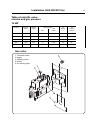
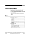
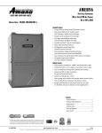
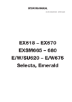
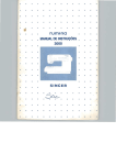
Operating and installation manual
Tumble dryer TT200 / TT270
Gas
(RMC)
487 14 49 71
English speaking countries outside EU
Tumble Dryer, drum volume 200/270 litres GAS
Contents:
Instructions for use:
General aspects ........................................................................................
Explanation.................................................................................................
Operation, manual residual moisture control..............................................
Maintenance ...............................................................................................
Installation:
Position.......................................................................................................
Dimension sketch gas heating....................................................................
Power connection .......................................................................................
Installation gas 12 kW ................................................................................
Technical Data ............................................................................................
Left/right hinged door..................................................................................
Evacuation system .....................................................................................
Examples of evacuation systems ...............................................................
Checking the functions ...............................................................................
PCB (printed circuit board), setting.............................................................
Quick-view parameter listing. .....................................................................
Parameter programming, residual moisture control ...................................
Parameter programming, changing parameters.........................................
Error codes .................................................................................................
1
2
3
4
5
6
7
8-11
12
13
14
15
16
17
18
19
20-21
22
Safety Instructions
This machine is intended for drying water-washed garments
alone.
The machine is not to be used for drying foam rubber or
materials similar to rubber.
The machine is not be used by minors.
The machine is not to be washed down with water.
Mechanical and electrical installation work are only to be
performed by authorized personnel.
In the case of machine fault, this is to be reported to the person
in charge as soon as possible. This is important for your own
safety and for the safety of other users.
The machine must not be installed in rooms with dry-cleaning
machines using PERCHLOROETHYLENE.
Remember that such textiles as silk and wool
are not to be dried in the tumbler.
The manufacturer reserves the right to alter design and material specifications
487 14 49-21/97.20
1
General Aspects
Drying is effected as follows:
•
The tumbling drum (1) rotates at constant speed in
order to keep the garments in movement all the
time.
•
An inbuilt fan (2) carries fresh air through
the machine.
•
The air first passes the heating unit (3), where it is
heated.
•
The air is then sucked into the drum via the
perforation at the back wall. It absorbs the
humidity in the garments and leaves the drum via
the perforation at the front of the drum.
•
Next the air passes a filter (4) which collects lint
and dust. The air is conducted out of the room via
the fan and the vent pipe system.
1
3
4
2
2
Instructions for Use
Explanation
Manual residual moisture control
C
A.
B.
C.
D.
E.
F.
G.
H.
I.
J.
Program selector
Temperature symbols
Lamp is lit for selected program
Start button
Lamp flashes / ready to start
Drying / lamp is lit
Cooling / lamp is lit
Drying time completed / lamp is lit
Filter / lamp is lit: Clean filter
Display indicates drying time
when time controlled is selected.
K. Timer buttons for desired drying time,
one press = one minut
L. Select residual moisture program by
pressing one of the following buttons:
1. Extra dry
2. Storage dry
3. Iron dry for iron
4. Iron dry for ironing machine
B
A
C
F
C
G
C
H
L
I
1
2
3
J
4
K
K
E
D
3
Instructions for Use
Manual operation with residual moisture control
Open filling door.
Fill garments into
drum.
Close door ➡.
Open filter door.
Clean filter.
Close filter door ➡.
Select drying
program.
Press program
button. Lamp is lit
for selected program
➡.
Airing.
without heat.
C
Mild wash.
Low heat.
C
C
PP / normal wash.
Normal heat.
Residual moisture
Extra dryt
Storage dry
Select
either
Iron dry (iron)
Time controlled
Iron dry (machine)
or
Residual moisture
Time control
one press
= one minut
Drying program:
Airing without heat
Mild wash, low heat
PP / normal wash, normal heat
Start:
Press start button.
In order to prevent
garments from
creasing:
Empty tumbler
immediately. ➡.
Drying time:
Set timer to:
c. 10 min.
c. 25 min.
c. 25 min.
Stop:
The tumbler can
always be stopped
by opening the
door.
Re-start:
Close door and
press start button.
Residual moisture:
Automatic program
with the following options:
Extra dry
Storage dry
Iron dry (for iron)
Iron dry (for machine)
The tumbler stops
automatically:
Time controlling:
- when the drying
time has expired
Residual moisture:
- When the selected
has been obtained.
Anti-crease
program ➡.
After the drying
time has ended,
the drum rotates at
short intervals until
door is opened.
Max. 1 hour.
4
Maintenance
Maintenance
The following work should be carried out at
regular intervals at a rate depending on the
frequency of use.
Daily
• Check that the drum stops when the door is
opened.
• Check that the lint screen has been cleaned.
The lint screen is to not be removed for
cleaning; just clean it with a soft brush or
your hand.
• Check that the lint screen is unbroken.
• Check that the machine will not start until
the start button has been activated.
• Check that the door glass is unbroken.
Every quarter / half year
• Check that the fresh-air intake at the back of
the tumbler is not clogged by lint or in any
other way.
• Check that the vent system is tight and not
clogged by lint/dust or in any other way.
• On machines with residual moisture automatic, the lifters in the drum should be
cleaned with a sponge at least once every
three months.
Annually
• Check that the fresh-air intake to the room
and the vent ducts/pipes in and from the
room are not clogged by lint/dust or in any
other way.
Clean as required - depending on the
frequency of use. Minimum once a year.
• At least once a year the inside parts of the
machine should be checked by a
competent, skilled person and cleaned for
lint.
5
Installation GAS 200/270 litres
Installation
1
Unpacking
500
Unpack the machine from its packaging.
There are no transport fittings.
Positioning
Place the tumble dryer in such a manner that the
work of both user and service technician
becomes as easy as possible. The door is
reversible (page 13).
1
Mechanical installation
Fig.
2
10
The distance from the wall or other equipment
behind the machine should be at least 500 mm;
distance on the sides at least 10 mm. Please
note that for the purpose of servicing there
should be access to the back of the machine.
2
Adjust the machine to make it horisontal - and
stable on all four feet.
The max. height adjustment of the feet is 50 mm.
When adjustment has been completed, lock the
feet with the lock nuts.
Installation onboard ship
Fig.
3
10
612
Fig.
The 4 accompanying fittings can be used to
secure the machine.
Secure the fittings to the base with four M10 set
screws.
3
6
Installation GAS 200/270 litres
792
48 (EL)
A
B
1508
Connection gas 1/2"
R61
2
137,5
51,5 (EL)
280
422
817
902
98
C
Drum volume
litres
Heating
effect
A
B
200
12 kW
827 mm 614 mm
∅ 160
270
12 kW
982 mm 769 mm
∅ 200
C
Blow-off branch
7
Installation GAS 200/270 litres
4
Electrical installation
To be carried out by a skilled, competent person.
The tumble dryer requires its own fuse group.
Fig.
4
3~:
L1
L2
L3
For each tumbler, place a multi-pole fixed switch
in the fixed installation. Place it in such a way
that it is easily accessible but will not be mistaken
for the tumbler main switch.
3N~:
The motor has an inbuilt thermo-fuse, which is
why motor protection is not required in the
installation.
Fig.
5
L1
L2
L3
L1
L2
L3
N
Remove the top cover from the tumbler in order
to connect the cable. Set up the tumbler as a
fixed installation. See dimensions in the table
below.
L1
L2
L3
N
1N~:
Before remounting the top cover: Check the
direction of rotation. See function checks, page
16. If the drum rotates in the wrong direction,
switch 2 phases.
L1
N
L1
N
The tumble dryer must be provided with extra
protection in accordance with relevant
regulations.
5
Cable dimensioning table
Drum
volume
Voltage
Power
input
Heating
Connecting lead
Dimension
Fuse
200/270 l
200-240V
1N 50/60 Hz
1,0 kW
Gas 12 kW
3 × 1,5 mm2
10A
200/270 l
400-440V 3N/3 50/60 Hz
0,5 kW
Gas 12 kW
2
5/4 × 1,5 mm
10A
200/270 l
200-230V
0,5 kW
Gas 12 kW
4 × 1,5 mm2
10A
3 50/60 Hz
Machines marked 230V or 400V (new European voltage as per IEC 38)
can be connected to 220V or 380V mains plugs without any problems.
8
Installation GAS 200/270 litres
Gas installation 12 kW
The installation must be performed by authorized
staff. Mount a manual shut-off valve prior to the
machine.
The gas pipe to the machine must be
dimensioned for a power output of 12 kW.
The machine is equipped with an allgas burner.
On delivery from the factory the machine is
adjusted to a nozzle pressure equivalent to the
calorific value indicated on the data sign.
Note! If you convert to another kind of gas a
corresponding sign enclosed must replace
the existing sign on the back of the machine.
Check that the nozzle pressure and the calorific
value correspond with the values indicated in the
table. If not, you must get in touch with the
supplyer.
Before connecting the machine the pipe must be
ventilated.
After connection all the connections must be
tested for leakage.
Test run 12 kW
Connect a pressure gauge to testsocket outlet
(1). (Page 11)
Select programme (Normal/perm.press)
Start the machine.
Check the nozzle pressure. See table page 11.
Any adjustment is carried out on the adjusting
screw (3) of the regulator under nipple (2).
Check that the gas flame burns steadily with
a bluish colour.
Having completed the test the machine is made
ready.
Installation GAS 200/270 litres
Conversion to town-gas 12 kW
Mount air reducing plate (6) with hole Ø 25.
Mount the enclosed nozzle on 5,6 mm (5).
Connect a pressure gauge to testsocket outlet (1).
Select programme (Normal/perm.press).
Start the machine.
Adjust nozzle pressure to 4,2 mbar on the
adjusting screw (3) under nippel (2).
Check that the gas flame burns steadily and with
a bluish colour.
Mount nipple (2).
Having completed the test the machine is made
ready.
9
10
Installation GAS 200/270 liter
Conversion to natural gas 12 kW
Mount air reducing plate (6) with hole Ø 25.
Mount nozzle (5) corresponding to gas type
(GNH/GNL), see table page 11.
Connect a pressure gauge to testsocket outlet (1).
Select programme (Normal/perm.press).
Start the machine.
Adjust nozzle pressure to 10,9 mbar on the
adjusting screw (3) under nippel (2).
Check that the gas flame burns steadily and with
a bluish colour.
Mount nipple (2).
Having completed the test the machine is made
ready.
Conversion to LPG gas 12 kW
Mount air reducing plate (6) with hole Ø 20.
Mount the enclosed nozzle on 1,8 mm (5).
Connect a pressure gauge to testsocket outlet (1).
Select programme (Normal/perm.press).
Start the machine.
Adjust nozzle pressure to 28 mbar on the
adjusting screw (3) under nippel (2).
Check that the gas flame burns steadily and with
a bluish colour.
Mount nipple (2).
Having completed the test the machine is made
ready.
11
Installation GAS 200/270 liter
Table of calorific value,
nozzles and gas pressure
12 kW
Gastype
Calorific
Value
Wobbeindex
Gas pressure
Inlet
Test
Outlet 1
Ø
Nozzle
5
Air
reducing
plate 6
Gas
pressure
switch 4
MJ/m3
MJ/m3
mbar
mbar
mm
Ø mm
mbar
LPG
126,4
87,3
30
28,0
1,8
20
20
GNH
37,4
47,9
18
10,9
3,1
25
10
GNL
33,6
42,0
18
10,9
3,4
25
10
GT
15,0
22,1
8
4,2
5,6
25
4
Gas valve
1. Testsocket outlet
2. Nipple
3. Adjusting screw
5. Nozzle
6. Air reducing plate
12
Installation GAS 200/270 liter
Technical data
Drum volume
Dimensions:
200 litre
270 litre
792 mm
827 mm
1508 mm
792 mm
982 mm
1508 mm
115 kg
130 kg
760 mm
440 mm
42 rpm
0,75
760 mm
595 mm
42 rpm
0,75
8,0 kg
6,0 kg
10,8 kg
8,2 kg
2 x 0,20 kW
2 x 0,25 kW
2800 rpm
3360 rpm
2 x 0,20 kW
2 x 0,25 kW
2800 rpm
3360 rpm
12 kW
12 kW
525 m3/h
525 m3/h
Ø 160
Ø 200
Width
Depth
Height
Net weigt:
Inner drum:
Diameter
Depth
Speed
G-factor
Capacity,
filling factor: 1:25
1:33
Motor:
Output kW:
Three phases
Single phase
Speed: 50 Hz
60 Hz
Heating gas:
Air evacuated: 12 kW
Pipe dimension: Air outlet 12 kW
Max. allowed pressure drop
of the evacuation pipe.
50 Hz 12 kW
60 Hz 12 kW
Gas valve connection:
gas pressure :
Sound pressure level :
Natural gas
LPG
GT
max.
max.
150 Pa
250 Pa
BSP 1/2”
BSP 1/2”
18 mbar
30 mbar
8 mbar
18 mbar
30 mbar
8 mbar
< 70 dB (A)
< 70 dB (A)
Installation GAS 200/270 litres
Left-/right-hung door
9
Reverse the door as follows:
Fig.
9
1.
2.
3.
4.
Disconnect the power to the machine.
Remove the top cover.
Remove the operating panel with the PCB by
removing the 2 multi-plugs, G1 and G2.
Remove the lock system, A.
Remove the 2 leads on the door switch.
Fig.
10
Remove screws B with gaskets and screws C
and E (fig. 9).
Remove screws D, taking care because the
door is now hanging loosely on the front
panel (fig. 9).
Fig.
11
5.
Switch cover plate and dust hood.
6.
Move the leads to the opposite side. Be
careful with the leads, so that they will not get
caught by the drum or when mounting the
front panel.
7.
Mount the front panel with door in such a way
that the hinges are on the opposite side.
8.
Mount the lock system, A (must be reversed).
9.
Mount the operating panel and the PCB.
Insert multi-plugs G1 and G2.
10.
Mount the top cover.
11.
Connect the machine to the power source
and test the machine.
10
11
13
14
Installation GAS 200/270 litres
12
Evacuation system
Fresh air intake
In order for the machine to work optimally, with
the shortest possible drying time, it is important
for the air intake to the room to come from the
open air and for the same amount of air as
enters the room to be evacuated. In order to
avoid draught in the room, it is best to place the
air intake behind the machine. See example
fig.12. The area of the air intake opening must be
5 times the area of the evacuation pipe. The
resistance in the damper / slatted shutter must
not exceed 10 Pa (0.1 mbar). The air
consumption is shown in the table. (Fig. 14).
Fig.
12
5×A
A
Evacuation pipe / duct
It is recommended to connect each machine to a
separate, smooth-faced evacuation pipe with as
low air resistance as possible.
13
The pipe must lead to the outside and be
protected against rain and impurities. The length
of the evacuation pipe is given in metres. For
each 90° bend - add 2 metres.
For each 45° bend - add 1 metre.
Set the damper in accordance with the table,
ensuring that the optimal efficiency is obtained.
Fig.
13
Lengths and dimensions can be seen from the
table.
Fig.
14
If in doubt with regard to the design of an
evacuation system, please do not hesitate to
contact our service organisation / dealer.
14
Hz
Type
in litres
Heating
Air
consumpt
Static
Diameter of
Setting of damper scale to
pressure evacuation pipe match different pipe lengths
0-15 m
15-30 m 30-60 m 60-100 m
200
12 kW
525 m3/h
150 Pa
160 mm
2
3
3-4
5
270
12 kW
525 m3/h
150 Pa
200 mm
2
3
3-4
5
200
12 kW
525 m3/h
250 Pa
160 mm
1
1-2
2-3
4-5
270
12 kW
525 m3/h
250 Pa
200 mm
1
1-2
2-3
4-5
50
60
Installation GAS 200/270 litres
Examples of evacuation system
Air outlet
Air inlet
Air inlet
Best position:
behind machine
15
16
Function checks 200/270 litres
Function checks, manual
15
Must be carried out by a skilled, competent
person.
Check that the drum is empty and the door
closed.
Fig.
15
Before start-up
Check the direction of rotation by pressing down
switch K3. If the drum rotates the wrong way,
switch 2 phases.
Fig.
16
The direction of rotation can be seen from fig. 16.
After start-up
Check that the safety lock works. The drum
must stop when the front door or filter door is
opened.
Let the machine run a program with heating
for 5 minutes. Check the heating by opening
the front door and checking that there is heat
in the drum.
If the above check-points are found to be in
order, the tumbler is ready for use.
If faults or deficiencies are found, please contact
your nearest service organisation / dealer.
Front
16
17
Electronic controls, 200/270 litres
PCB (printed circuit board), setting of 200/270 -litre machine
The switch setting (variant setting) for the 200/270-litre model.
The PCB has been preset at the works to match this model.
Only if the PCB is replaced is it necessary to reset.
OPEN
1 2 3 4 5 6 7 8
RMC
Manual with moisture sensing
Switch no. 6:
Closed = Reversing possible
OPEN = No reversing. (this possibility is thus removed
from the parameter programming).
230V EXTERNAL TIMER
+ 24V CALCAD/CP
–
SERVICE PROGRAM
ELECTRODE FOR
MOISTURE SENSING
CALCAD INTELLIGENT
COMMUNICATION
COIN 2
SETTING OF VARIANT
(200/270 model)
COIN 1
TC
OUTLET THERMISTOR
INLET THERMISTOR
18
Parameter programming, 200/270
Quick-view parameter listing
The following values have been pre-programmed:
Parameter
No.
Value /
setting
Parameter
01
3.0
Cooling time
02
50
Program with low temperature: 50°C
03
70
Program with high temperature: 70°C
04
90
Maximum running time
05
1
With reversing
06
2.3
Reversing time
07
3
16
n6
17
0
18
13
Program: Iron dry (iron)
19
21
Program: Iron dry (flatbed ironer)
Reversing, pausing time
Program: Extra dry
Program: Dry
A more detailed explanation of the parameter programming can be found on the following pages.
19
Parameter programming 200/270 litres
Applies only to machines with RMC.
At the works, the tumbler has been set at a specific value, such as: length of running time per
coin, temperature, cooling, reversing, etc.
These different parameters (number of parameters can vary from type to type) can be
changed by turning the key switch at the front of the machine (cannot be engaged when the
machine is in operation or the door closed).
When engaging the program, always start with parameter 01.
Press the start button (Enter) repeatedly to reach the parameter number to be changed.
When the parameter programming is engaged, the LEDs indicate the current parameter:
LED Drying
=
LED Cooling
=
LED Key
=
LED Filter
=
Parameter 1 - 7
C
Drying
C
Cooling
Count upwards
Count downwards
C
Key
Reset
Factory setting.
Parameter 16-19
Filter
16
Storage dry +
6 minutes extra drying.
Display
17
Storage dry
18
Iron dry
for iron
19
Iron dry
for ironing machine.
Enter
Stores value.
Shift to next
parameter
20
Parameter programming 200/270 litres
Parameters
1-7
LED:
On
=
Off
=
Value,
factory setting
Cool-down time
C
C
C
To change :
Press button for:
C
1
Longer time
Value = Min. sec. 0,0 - 9,6
C
Shorter time
Factory setting: 3,0
C
Factory setting
Store value/
shift to next
Temperature 50°
(HP = 45°)
C
C
C
Temperature 70°
(HP = 53°)
C
C
C
Maximum
running time
per start
2
3
Value = Degrees C. ± 7°C
C
Factory setting: 50°C
C
Lower max. 7°
C
Factory setting
Special factory setting for machine
with heat pump (HP)
Value : min. 40°C, max. 50°C
Factory setting: 45°C
Store value/
shift to next
Value = Degrees C. ± 7°C
C
Factory setting: 70°C
C
Special factory setting for machine
with heat pump (HP)
Value : min. 50°C, max. 60°C
Factory setting: 53°C
C
Higher max. 7°
Lower max. 7°
Factory setting
Store value/
shift to next
C
4
Higher max. 7°
Longer time
Value = Minutes 15 - 90
C
Shorter time
Factory setting: 40
C
Factory setting
Store value/
shift to next
C
Reversing
5
Value = 1 / 0
With/without reversing
With revers. =1
C
W.out revers.=0
C
Factory setting
Factory setting: 1 med
Store value/
shift to next
C
Reversing time
6
Longer time
Value = Min. sec. 0,2 - 9,6
C
Shorter time
Factory setting: 2,3
C
Factory setting
Store value/
shift to next
Reversing
pause time
C
7
Longer time
Value = Sec. 3 - 20
C
Shorter time
Factory setting: 3
C
Factory setting
Store value/
shift to next
Concerning machines with Residual moisture control program:
Go to parameter 16 (page 26).
Parameter programming 200/270 litres
21
Only on machines with residual moisture control
Parameter
16-19
Residual
moisture
control
Extra dry
Residual
moisture
control
Dry
Residual
moisture
control
Iron dry
Residual
moisture
control
Iron dry
for
ironing machine
LED:
On
=
Off
=
16
17
Value,
factory setting
Value = Residual moisture n9 - 30%
Factory setting: n6
n6 = 0% + 6 minutes’ extra drying
(n1 - n9 = 1-9 minutes)
To change :
Press button for:
C
Lower %
C
Factory setting
Store value/
shift to next
C
Higher %
Value = Humidity 0 - 30 %
C
Lower %
Factory setting: 0 %
C
Factory setting
Store value/
shift to next
C
18
Higher %
C
Higher %
Value = Humidity 0 - 30 %
C
Lower %
Factory setting: 13 %
C
Factory setting
Store value/
shift to next
C
Higher %
19
Value = Humidity 0 - 30 %
C
Factory setting: 21 %
C
Note! Parameters 8 - 15 are not used (with residual moisture control).
Lower %
Factory setting
Store value/
shift to next
22
Installation 200/270 litres
Error codes
The machine features automatic error reporting,
shown in the form of flashing error codes.
Error code
Error
What is wrong/what needs doing?
Brown-out
20% reduction of the voltage from the power station:
Can be restarted when current returns to normal.
Heating error
Fault on inlet sensor or heating element. Disconnect
current for a moment. If the fault repeats itself, call in
service.
Outlet sensor
Outlet sensor faulty. Disconnect voltage for a moment.
If the fault repeats itself, call in service.
Wrong variant
Wrong combination of switches on the PCB.
All lamps go out. Call in service.
Electronic error
Micro-processor error: Call in service.
Service program
Service program illegally engaged:
Must only be used with the door open.
Vacuum switch
Vacuum switch fault: Call in service.
Number of error codes can vary from type to type.