1
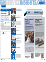
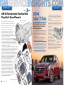
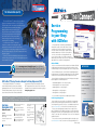
ServiceInsights FO R IN DEPE N D E N T SE RV I C E C E NTE R S JAN–MAR 2014 Cadillac CTS – 2014 Motor Trend Car of the Year ALSO IN THIS ISSUE More Stories, Pictures and Resources at GM ServiceInsights.com Chevrolet Performance Packs SEMA with Power GM Transmissions Shine Bright at AAPEX and ATRA Millions of 6-Speeds, Overhaul Kits Available More GM Parts Training Clinics on the Way Simply Rewarding with Genuine GM Rewards TechConnect Insert Power-Dense Powertrains Underpin Its Performance Twin-Turbo V-6 Partnered with 8-Speed Automatic More Inside: 2014 CTS Service Procedures Genuine GM Parts Resources Online GMSERVICEInsights.com Contents 3 / Chevrolet Performance at SEMA GM ServiceInsights Online Chevrolet packed SEMA with power. Read more at GMServiceInsights.com. More Genuine GM Parts resources and links. GMServiCEInsights. 3 3 / GM Transmissions Shine Bright Download this issue and past issues of GM ServiceInsights magazine at... GM TEHCM display draws crowds at AAPEX and ATRA shows. Read more at GMServiceInsights.com. www.gmserviceinsights.com GM ServiceInsights Headquarters 2604 N.E. Industrial Dr., #230 N. Kansas City, MO 64117 Email: [email protected] All the stories in Service Insights, additional content and pictures available at gmserviceinsights.com 3 4 / GM 6-Speed Overhaul Kits We Support Voluntary Certification National Institute for AUTOMOTIVE SERVICE EXCELLENCE www.ase.com Growing population of 6-speeds can mean repair opportunities for older vehicles using GM Overhaul Kits. Compliments of your GM dealer. We invite your input and suggestions. Please address letters to the editor to the above address. Letters submitted imply the right to edit and publish. Every effort is made to ensure the accuracy of the information in the offers contained in this magazine. However, printing and typographical errors may occur. These are not intentional and are not the responsibility of GM, any dealer or the companies or individuals who create, produce and distribute this magazine. Offers and pricing may change at any time without prior notification. The descriptions and specifications in this publication were in effect at the time of approval for printing. General Motors reserves the right to change specifications without notice and without obligation. Published letters do not necessarily reflect the opinions of General Motors or General Motors Parts. General Motors, Detroit, MI 48202. © 2014 General Motors • All rights reserved. 4 5 / 2014 Cadillac CTS Sedan Twin-Turbo V-6 packs a wallop with Motor Trends’s Car of the Year, the 2014 Cadillac CTS. Chevrolet Performance in Full Stride at SEMA 2013 Exciting new concepts exhibited along with commercial powertrain solutions. Chevrolet Performance strutted its stuff at the annual Specialty Equipment Manufacturers Association (SEMA) show last November. 6 6 / Cadillac CTS Service Procedures 6 www.gmtechinfo.com offers access for service manuals and other repair resources. Follow this example of Fuel Pump Replacement for the LF3 engine in the 2014 Cadillac CTS. Priming the Pump for TEHCMs OE Control Module/Programming for GM 6-Speeds Get Big Exposure at AAPEX, ATRA Shows After two big auto service industry shows in 2013, independent service centers are buzzing about “TEHCMs” in early 2014. The TEHCM — shorthand for the Transmission Electro Hydraulic Control Module used in GM 6-speed vehicles — was an attention-getter at two events last fall: the Automotive Aftermarket Products Expo (AAPEX); and the Automatic Transmission Rebuilders Association (ATRA) show. Thousands of auto service professionals attending the shows had a chance to see the GM TEHCM display and learn how easy it is to program one. TEHCM Front 8 / GM Parts Training Clinics GM dealers offering GM Parts Training Clinics help ISCs build knowledge. Additional clinic topics in 2014. 8 10 / Genuine GM Rewards 10 Progra Low Battery mming and Parasit icwith Drains ACDelco The next The Engine Control screen, (ECM), the Body Control Module Module • Retained Accessory (BCM),Supporte continued OnStar,d Power off – Automatic Climate open and close the 5. Turn the EL Control, Remote Controlle 38758 switch knob driver door after from page Keyless Entry Receiver rs, the ignition is off to the ON displays To position. — these help avoid are the just a few of the control 4 damage off the vehicle control modules • Scan tool not that could 6. Road to a control modcause a high parasitic test the vehicle communicating with ignition instructed and during drain,ules activate all module, do leading a vehicle control that to a of the accessories dead battery/no to do such a programm module not so. as the radio start condition. can be proing event turn and Program air conditioning. • All access doors unless grammed If diagnosis reveals ming Comple closed the batteryon 7. Ignition is in otherwise good that the te Once • Headlamps off off.the vehicle. Connect a 10A fused – auto headlamps download and is jumper capable of holding condition In the screenwire disabled is complete top withto the test switch a charge, and tool , you’ll terminals. the charging system menu, that some final a Programm Select see a summary ing Complete • Any delay lighting instructio the cause may be a parasitic is OK, Controlle ns. off 8. Turn drain on the battery. r, • the EL 38758 switch(Fig. 13) These message along Post-prog select the A parasitic drain • Underhood lamp with ramming knob to instructio is an the OFF disabled position. module-s ns include: instructio The current that controlload draws current from electrical Fig. 9 pecific Verify the module flowsming the vehicle's • HVAC afterblow through instructionowns: Follow these the jumper battery to the prowhen the ignition process off VIN wire.ns to complete control is turned off. 9. Check grammed • Clear • Disable or turn the programthe DTCs: fuse in the jumper . Intended Drain off any wire. accessory Clear The – Some control fuse that can work with that set should be OK.any Diagnost In the during the If the the ignition off arebyintended Service programming is modules used today Originalto Equipment jumper ic Trouble draw a very thewire programm fuse is blown, “Clear bottom small amount • Wait up to two refer toing process Codes (DTC) manufacturers to update control module continuously. software to improve DTCs” button Circuit/System Testing. minutes or longer, Other conmenu, trol operations. • Proceed by selecting modules may If the fuse is after all other listed or modify a variety of vehicle Most Select OK, proceed be manufacturprogrammed with same conditions Programm to wakeregularly 10. VIN: another to step are met. up, perform ers release software revisions to update engine anding a task,Type, then go 10. Turn the EL control module Select this option back to well sleepasatother select transmission calibrations as system operations. regular • New: 38758 switch knob intervals. on the to program Simplified Parasitic These to same Normal, the ON Select this draws are measured position. vehicle. and Remove in then optionthe out starting milliamps Using an Inductive Draw Test At times, control modules can be reprogrammed in order jumper to fused program wire. the SPS click (mA). Pickup Probe Some another systems to correct a vehicle condition. If the condition caused process “Next.”by a areisdesigned vehicle 1. Connect an inductive from the 11. Connect a DMM to must remain on (in ahowever, withstandby power malfunctioning control module, then the module be beginning between the test (Fig. state) 10) that can read down pickup probe after the . switch tool terminals. ignition is turned replaced and the new module must be reprogrammed. to 1 mA to the off, with a resulting negative battery to the 10A DC scale. Set the meter Select parasitic drain. On-times cable. vary with the ACDelco TEHCMs system, although Fig. 10 2. With 12. Turn the EL theSupported a ruleCalibra ignition off, as the tions of thumb 38758 switch knob is that most systems Controller vehicle systems shut down, to ACDelco now offers Transmission Electrowill Hydraulic Control Modules (TEHCM) the OFF position. s Now go to sleep Current now flows the model (off) year vehicles. for within less INtest THIS ISSUE 30 minutes, than 30 mA for GM 6-speed automatic transmissions in while 2007 and later through the DMM. system others willmay into a single module. of parasitic current drain. take up toand twohydraulic The TEHCMs integrate electronic hours. listcomponents 3. If the parasitic the cali13. As the vehicle current is greater systems shut down, brations Unintended Service Programming in your test for than ACDelco TEHCMs provide your customers GM Original Equipment parts, 30 Drain with mA, for – Unintended less than 30 mA proceed to the Circuit/ programm parasitic drains of parasitic Shop with ACDelco . . . . . . . . . . .current . . . . . . . . drain. . .1 including a filter plate, solenoids and anmay upgraded frame, and the latest System calibration Test. be ing. caused by a fuel economy. Select stucktransmission relay or switch, software to deliver smooth shifts optimized the orand a dome 14. If .the Using a Parasitic FNC Brake Rotor Service Update . . . .parasitic . . . .2 lamp system or luggage compartment current Draw Test lamp remain- partsSwitch Along with using Dexron VI continuously. transmission fluid, theand following are required, than 30 mA, proceed is greater the calibratio ing on (such as Tool to Low Battery and Parasitic Drains . . . . . . . . . 3 the These EL Circuit/ 38758) drawsnwill based on application, with TEHCM replacement: System Test. you want typically be measured The knob on the in amps to (A). EL 38758 switchTool The Smartest Toolbox . . . . . . . . 6 from • 6T30/40/45/50 applications – valve bodyload cover gasket is in YourCIRCUIT/SYSTE marked ON and Normally, the OFF. the ON position, intendedCalibratio M TEST parasiticndrains the negative battery InInstalling aren't a cause Cabin Air Filter .Removing . . . . . . . . . . . . . .6 • 6T70/75 applications – valve bodyfor cover gasket and cable circuita is Index concern, a fuse, relay, or because they menus. completed and electrical are low, and the connector may wake current will pass In theis History replenished • 6L45/50 applications – seal panbattery gasket through the switch. Fuel Module Design Changes. . . . . . . . up . . .control .6 modules. Wait for each time kit, the vehicle the control .modules In the OFF window, is driven. Fig. Fig. 11 Calibration the to 13 circuit go back is open and electrical position, Summary to sleep • 6L80 applicationsPARASITIC – seal kit, pan gasket the changes Tech Tipscurrent . . . . . . . . . . . . .before . . . . . . . .retesting. . . . . . . . . . 7 Fuses Selection screen will not pass through DRAW for power mode TEST After programm master included the switch. components such • 6L90 applications – Aseal kit, pan gasket in the detailed parasitic .should . . . .some . . . .be . . . . . . . . . 8 ing, someas the BCM When a fused jumper Training Update . . . . . .that calibratio removed last to control draw test relearn n arewill depend tonosis. See your local ACDelco representative for additional part information. modules on the equipment the appropria multimeter is connected wire or digital setup avoid misdiagdetailed. A scan toolorconnected may require on the Click to the test te Service procedur specific vehicle being to thees be switch terminals, can “Next” complete the parasitic tested. Informati DLC For affect Service Programming System always turn the once Refer to more informati current the vehicle's d. Refer on. draw. test www.acdelcotechconnect.com, switch ON before theInformation Service to www.acd desired on opening any door, If thelink for the reprogramming vehicle details. click the Newsletters When installing a new control such a TEHCM, has an about The module elcotechc turning the ignition service calibratio following unacceptable Informati is aas generic programm amounton onnect.co on, or turning any n has test. tool accessory ofSystem parasitic current procedure can be performed quickly using J2534 interface and the GM beena selected. ing, go m and click draw, at remove on. This Preliminary 1-888-212 link, or call each Steps the Technica fuse one at Service Programming System (SPS). Access to SPS is available through ACDelco. is to prevent acci-8959 dently blowing (Fig. 11) ACDelco a time word until the the jumper wire current l technical concerns Aftermar draw, fallsfor fuse or 1-800-825 There are Go to www.acdelcotds.com, themany onlinethings ACDelco Technical Delivery System. to an acceptable digital support. ket Support contact multimeter fuse. A drop of that can For I.D. the ACDelco level. moreprompt -5886, prevent the vehicle The system than 10–20 mA, when systems from Click the Service and Programming Information link on the right of theoff. eBusines and passupdate 1. side disabling a single Ignition 3. Service completely should Disconnect the battery s Helpdesk Programmsystem or circuit, is an to sleep page. It will display a list of GMgoing Calibration andand Diagnostic subscriptions, start indication at pass- Software negative at http://ser downof an overly ing the cable ing System high current draw draw vice.gm.c Service Programming options: 2 days – $55; 3 months from the battery. including prices for several parasitic test. Make loading that could user guides User all of om/userg to the sure 2. Guides be causing following the battery the EL 38758 switch are available conditions – $275; or 1 year – $995.the Click “Subscribe Now” to select one of theTurn subscriptions drain. link uides/ind control are at TIS2Web met knob the before performing module Fig. 12the OFF to ex.pdf; or Refer to the the parasitic current Transferposition. Scanpage the code to bottom (registration required). Follow ACDelco automatic of the click the on vehicle's wiring acdelcote Data screen displays draw test. schematics Service chconnec Service Informati to download a PDF diagnose exactly 3. Installa progress A progressally. Programm the t.com. on/ which Once you have a user name, password and have paid for a subscription, log male on bar end of the EL circuit of bar will requirem ing System suspect • Ignition off (Fig. 12) show 38758 systemhardware entsthe switch to the battery is causto www.acdelcotds.com. Here’s an overview of the SPS programming process. when the can ing the com/pdfs be found high parasitic download negative drain. and /GM_Dea at Perform terminal. software • Key out of the http://ww the necessary repairs is complete continued on page 4 ler_IT_Gu ignition – Thanks w.gmdes following idelines.p appropriate . equipped with keyless switch (if not 4. Install the battery to Rick olutions. procedures. df Balabon negative cable start) to the female end – Thanks to Todd of the EL 38758 Merkle switch. and John Munsell Service Programming in your Shop with ACDelco 2 Jan – Mar 2014 ServiceInsights – Buy parts. Earn reward points. Redeem for free merchandise. It’s that simple with Genuine GM Rewards. Read more at GMServiceInsights.com. TechConnect Insert TechConnect is a magazine to help professional technicians improve their knowledge and understanding of today’s increasingly complex vehicles. Team Chevrolet race drivers Ron Fellows (left center), and Danica Patrick sign autographs in the Chevrolet Performance exhibit at the 2013 SEMA Show in Las Vegas, Nev. There’s a lot new for Chevrolet Performance to crow about in 2014, and the big Las Vegas event was the launching pad. Chevrolet’s power-packed SEMA booth showed the brand at its creative best. On display were new powertrain products and the most extensive lineup of new Chevrolet highperformance concept vehicles in two decades. For pictures of the 2013 SEMA and to read the rest of the story go to gmserviceinsights.com. TEHCM Back Both the OE module and the programming tools are newly available to Independent Service Centers (ISCs). That presents a brand new opportunity for ISCs to service GM 6-speeds. It’s potentially big business. Some 7 million GM 2007-2014 model-year vehicles have 6-speed transmissions with a TEHCM. For more pictures, video links and to read the rest of the story on AAPEX and ATRA Shows, go to gmserviceinsights.com Jan – Mar 2014 ServiceInsights 3 GMSERVICEInsights.com GM OE Parts Update The Technical Side GM OE Transmission Overhaul Kits Simplify 6-Speed Repairs When a complete transmission replacement doesn’t seem economical or feasible for your GM 6-speed transmission customer, another option could be a transmission overhaul. GM helps make this easy for Independent Service Centers (ISCs) and transmission shops with a variety of available of 6-speed transmission OE overhaul kits. Kits are available for the range of front-wheel drive transmissions (6T30-40-45-50-70 and 6T75), and rear-wheel drive transmissions (6L45-50-80 and 6L90). Each kit consists of all the replacement parts needed to correct a specific internal transmission problem. Seals, bonded pistons, gaskets and hard parts (gear sets) are examples of some of the part-specific kits available. By ordering one part number you can simplify the process of ordering multiple parts once the problem is isolated in the course of a teardown. GM picked up the pace of adding new kits in 2013 and will continue to add to the lineup. With 7 million GM 6-speed vehicles built between 2007 and 2013 are aging, and another 6 million 6-speed vehicles on course to be built between 2014 and 2017, demand will be increasing. “Overhaul kits have been available for some time, but with such a huge number of 6-speed vehicles hitting the road we’ll be looking to introduce more of them as the vehicle applications expand and we identify specific kits based on customer demand,” says Shelly Jacobs, GM Customer Care & Aftersales product specialist, Transmission Components & Hybrid Batteries. “Our aim is to offer as many of the various combinations and levels of overhaul kits as we feasibly can, realizing that the kit format is the easiest and most economical way for rebuilders to purchase the parts needed for a typical overhaul.” GM makes it easy to identify and order the exact kit needed for the overhaul. The Genuine GM Parts Powertrain Catalog, accessible at http://gmpowertrain. nexpart.com/, contains exploded views of transmissions that identify the exact parts needed and the appropriate kit, if available. In the event a kit is not available, parts can be ordered individually from your GM dealer. GM Hydra-Matic 6L90 (MYD) 6-speed RWD Automatic Transmission 2014 Cadillac CTS Sedan Performance Driven by the All-New Cadillac Twin-Turbo V-6 Partnered with 8-Speed Automatic Cadillac’s all-new 2014 CTS sedan ascends into the heart of the midsize luxury market with expanded performance, elevated luxury and sophisticated technology. It will be the segment’s lightest car, enabling the most agile driving dynamics in the class. A range of power-dense powertrains underpin its performance, including the all-new Cadillac Twin-Turbo engine and 8-speed automatic transmission. The 2014 Cadillac CTS sedan is the Motor Trend Car of the Year for 2014. The third-generation CTS sedan is based on the high-performing rear-drive architecture of the award-winning ATS sport sedan, moving Cadillac into the prestigious class of midsize luxury sedans. While stretched in overall length and wheelbase, the allnew CTS sedan has a lower curb weight than the preceding model and weighs about 200 pounds (90 kg) less than the BMW 528i. The Cadillac Twin-Turbo V-6 is the most power-dense six-cylinder engine in the midsize luxury segment – a 3.6L with 118 horsepower per liter (88 kW/liter) – and the 8-speed automatic enhances fuel economy and acceleration over a 6-speed automatic. Rated at an SAE-certified 420 horsepower (313 kW) and 430 lb.-ft. of torque (583 Nm), it is the most powerful V-6 ever from General Motors. It also has 15 percent greater power density than 2014 TL80 (MGG) 8-Speed BMW 535i’s turbocharged 3.0L six, RWD Automatic Transmission which is rated at 300 horsepower for Cadillac CTS (223 kW), for a ratio of 100 horsepower per liter (74 kW/liter) — and even the BMW 550i’s TwinPower 4.4L V-8, rated at 400 horsepower (298 kW), or 91 horsepower per liter (68 kW/liter). Power density is a measure of efficiency for an engine’s size. Typical GM OE Transmission Overhaul Kit 4 Jan – Mar 2014 ServiceInsights Jan – Mar 2014 ServiceInsights 5 GMSERVICEInsights.com SPECIAL INSERT The Technical Side (cont’d.) The all-new 2014 Cadillac CTS sedan will offer three different engine options including the 2014 3.6L V-6 VVT DI Twin Turbo (LF3) with a pair of smaller turbochargers and an efficient charge air cooler help provide more immediate power delivery. Additionally, approximately 90 percent of the 3.6L Twin-Turbo’s peak torque is available from 2,500 rpm to 5,500 rpm, giving the engine a broad torque curve that customers will feel as strong, willing power in almost all driving conditions, such as accelerating or overtaking traffic on the highway. Those features help the new CTS sedan reach 60 mph from a standstill in an estimated 4.6 seconds and achieve an estimated top speed of 170 mph (274 kph). The new engine is a comprehensive upgrade on the 60-degree, 3.6L DOHC V-6 offered in today’s SRX, XTS and ATS. However, almost every component is unique. The 2014 CTS sedan is also available with the naturally aspirated 3.6L V-6 rated at 321 horsepower, as well as a 2.0L turbocharged engine rated at an estimated 272 horsepower. Service Programming in your Shop with ACDelco Service programming is used today by Original Equipment manufacturers to update control module software to improve or modify a variety of vehicle operations. Most manufacturers release software revisions regularly to update engine and transmission calibrations as well as other system operations. At times, control modules can be reprogrammed in order to correct a vehicle condition. If the condition is caused by a malfunctioning control module, however, then the module must be replaced and the new module must be reprogrammed. ACDelco TEHCMs ACDelco now offers Transmission Electro Hydraulic Control Modules (TEHCM) for GM 6-speed automatic transmissions in 2007 and later model year vehicles. The TEHCMs integrate electronic and hydraulic components into a single module. Go to www.gmserviceinsights.com for additional powertrain features for the Cadillac Twin-Turbo V-6 along with video links for the engine. ACDelco TEHCMs provide your customers with GM Original Equipment parts, including a filter plate, solenoids and an upgraded frame, and the latest calibration software to deliver smooth transmission shifts and optimized fuel economy. Along with using Dexron VI transmission fluid, the following parts are required, based on application, with TEHCM replacement: 2014 Cadillac CTS Service Procedures Example Fuel Pump Replacement (LF3) Even though the 2014 Cadillac CTS is a new vehicle, service and repair information resources are a click away at www.gmtechinfo.com — Electronic Service Information. Technicians and shop owners can log on to the site to gain access to subscription services for service procedures and repair manuals. A complete Service Manual is accessible 24/7 through a subscription to the site. Free collision repair procedures will soon be available for the vehicles by going to www.genuinegmparts.com. Fuel Pump Replacement (LF3) Removal Procedure Special Tools EN 48896 HP Fuel Pump Installation Alignment Gauge For equivalent regional tools, refer to Special Tools. 6 Jan – Mar 2014 ServiceInsights 1 2 3 4 Relieve the fuel pressure. Refer to Fuel Pressure Relief. Remove and DISCARD the fuel feed pipe. Refer to Fuel Feed Pipe Replacement. Remove and DISCARD the fuel feed intermediate pipe. Refer to Fuel Feed Intermediate Pipe Replacement. Remove and DISCARD the high pressure fuel pump bolts (1). 1. Remove the high pressure fuel pump (2). Installing a Cabin Air Filter . . . . . . . . . . . . . . . 6 • 6L45/50 applications – seal kit, pan gasket Fuel Module Design Changes. . . . . . . . . . . . . 6 • 6L80 applications – seal kit, pan gasket Tech Tips . . . . . . . . . . . . . . . . . . . . . . . . . . . . . . 7 When installing a new control module such as a TEHCM, the reprogramming procedure can be performed quickly using a J2534 interface tool and the GM Service Programming System (SPS). Access to SPS is available through ACDelco. Go to www.acdelcotds.com, the online ACDelco Technical Delivery System. Click the Service and Programming Information link on the right side of the page. It will display a list of GM Calibration and Diagnostic Software subscriptions, including prices for several Service Programming options: 2 days – $55; 3 months – $275; or 1 year – $995. Click “Subscribe Now” to select one of the subscriptions (registration required). 3. Remove and DISCARD the high pressure fuel pump gasket (4). 4. Remove and DISCARD the high pressure fuel pump O-ring (5). Once you have a user name, password and have paid for a subscription, log on to www.acdelcotds.com. Here’s an overview of the SPS programming process. continued on page 4 continued on page 7 Low Battery and Parasitic Drains . . . . . . . . . 3 • 6T70/75 applications – valve body cover gasket Service Programming System 2. R emove the valve lifter follower (3). FNC Brake Rotor Service Update . . . . . . . . . 2 The Smartest Tool in Your Toolbox . . . . . . . . 6 See your local ACDelco representative for additional part information. 4 Service Programming in your Shop with ACDelco . . . . . . . . . . . . . . . . . . . . . 1 • 6T30/40/45/50 applications – valve body cover gasket • 6L90 applications – seal kit, pan gasket 2014 Cadillac CTS Sedan (VIN A) | CTS Sedan Service Manual 6103955 | Engine/Propulsion | Engine Controls and Fuel - 3.6L LFX LF3 | Repair Instructions | Document ID: 3599796 IN THIS ISSUE Training Update . . . . . . . . . . . . . . . . . . . . . . . . 8 www.acdelcotechconnect.com, click the Newsletters link Follow ACDelco Scan the code to download a PDF FNC Brake Rotor Service Update GM’s exclusive Ferritic NitroCarburizing (FNC) technology is applied to brake rotors on many GM models, including the Cadillac DTS, ATS and new 2014 CTS; Buick Lucerne Super, LaCrosse, and Regal; Chevrolet Impala, Malibu, Volt, and the new 2014 Corvette and Silverado 1500; and the new 2014 GMC Sierra 1500, to extend the life and appearance of the rotors. These rotors can be serviced the same as regular non-FNC brake rotors. The FNC heat treatment — similar to carburizing used in powertrain gear hardening — involves an additional manufacturing process that heats the rotors at 560°C for up to 24 hours, where nitrogen atoms bond to the surface of the steel rotor, hardening and strengthening the rotor to provide slower wear and reduced corrosion. Servicing FNC Rotors When refinishing FNC rotors, the FNC layer will be removed from the brake surface of the rotor. This is acceptable and the rotor will perform as a regular non-FNC rotor. Do not refinish the FNC rotors unless the rotors are determined to be the cause of the brake concern. Do not refinish brake rotors for concerns such as brake noise, uneven or premature brake pad wear, cosmetic corrosion of the brake rotor surface or scoring of the rotor surface less than the maximum allowable specification. Before refinishing, measure the rotor’s thickness using a brake micrometer at multiple points. Document the lowest measurement. Reference the Minimum Thickness specification stamped on the backside of the rotor. Removing the FNC layer, just as with any rotor refinishing, can change the rotor output. Only remove the necessary amount of material from each side of the rotor. Equal amounts of material do not have to be removed from both sides on any brake system using a floating caliper. Typical brake roto When refinishing rotors, it is critical that the brake lathe is properly calibrated and well maintained to ensure a proper cut. Calibration of the brake lathe should be performed on a monthly basis. Thoroughly clean the rotor with soap and water after refinishing to prevent the possible transfer of finite metal dust left as a by-product of refinishing to the pad material during the seating process. This reduces the opportunity for brake noises to occur. Brake rotors should only be refinished if they have adequate thickness. Conditions for refinishing rotors include: FNC treated rotor The unique FNC process lays down a 10-micron-thick transfer layer, equivalent to one-tenth the width of a human hair, across the entire rotor surface as well as the center “hat” section and inside the central cooling vanes of ventilated rotors. The strong surface created by the FNC treatment helps Low Battery and Parasitic Drains reduce rotor thickness variation caused by an uneven buildup of rust on the rotor that occurs over time. • Thickness variation in excess of the maximum allowable specification • Excessive corrosion or pitting • Cracks or heat spots • Excessive blueing discoloration • Scoring of the rotor surface in excess of the maximum allowable specification – Thanks to Kyle Beane and Kent Wilson 2 Tech Connect Volume 20, Number 6 (TS-PU-0006-13) ACDelco TechConnect is published bi-monthly and online for technicians of Professional Service Center and Key Fleet accounts to provide timely service information, increase knowledge and improve the performance of the service center. ACDelco 360 represents our mission to look at our businesses at every possible angle to provide value and assistance to our distributors and their customers as well as offer a full circle of support with programs, tools, training and marketing focused on enhancing and growing our partnership successfully. Publisher: Rick Balabon ACDelco E-mail [email protected] Editor: Greg St. Aubin ACDelco E-mail [email protected] Technical Editor: Mark Spencer E-mail [email protected] Production Manager: Marie Meredith Desktop Publishing: 5by5 Design LLC E-mail [email protected] Write to: ACDelco TechConnect P.O. Box 500 Troy, MI 48007-0500 On the Web: To read or print recent issues of TechConnect: – www.acdelcotechconnect.com, click the Newsletters link. ACDelco service tips are intended for use by professional technicians, not a “do-it-yourselfer.” They are written to inform those technicians of conditions that may occur on some vehicles, or to provide information that could assist in the proper service of a vehicle. Properly trained technicians have the equipment, tools, safety instructions and know-how to do a job properly and safely. If a condition is described, it cannot be assumed that the information applies to all vehicles or that all vehicles will have that condition. All materials and programs described in this magazine are subject to change. Submission of materials implies the right to edit and publish. Inclusion in the publication is not necessarily an endorsement of the individual or the company. TechConnect is published for ACDelco by Sandy Corporation, Troy, MI. ©2013 ACDelco. All rights reserved. The Engine Control Module (ECM), the Body Control Module (BCM), OnStar, Automatic Climate Control, Remote Keyless Entry Receiver — these are just a few of the control modules that could cause a high parasitic drain, leading to a dead battery/no start condition. • Retained Accessory Power off – open and close the driver door after the ignition is off If diagnosis reveals that the battery is in otherwise good condition and is capable of holding a charge, and that the charging system is OK, the cause may be a parasitic drain on the battery. A parasitic drain is an electrical load that draws current from the vehicle's battery when the ignition is turned off. • Headlamps off – auto headlamps disabled Intended Drain – Some control modules are intended to draw a very small amount continuously. Other control modules may be programmed to wake up, perform a task, then go back to sleep at regular intervals. These draws are measured in milliamps (mA). Some systems are designed to remain on (in a standby power state) after the ignition is turned off, with a resulting parasitic drain. On-times vary with the system, although a rule of thumb is that most systems will go to sleep (off) within 30 minutes, while others may take up to two hours. Unintended Drain – Unintended parasitic drains may be caused by a stuck relay or switch, or a dome lamp or luggage compartment lamp remaining on continuously. These draws will typically be measured in amps (A). Normally, intended parasitic drains aren't a cause for concern, because they are low, and the battery is replenished each time the vehicle is driven. PARASITIC DRAW TEST A detailed parasitic draw test will depend on the equipment on the specific vehicle being tested. Refer to the vehicle's Service Information for details. The following is a generic test. Preliminary Steps There are many things that can prevent the vehicle systems from completely going to sleep and passing the parasitic draw test. Make sure all of the following conditions are met before performing the parasitic current draw test. • Scan tool not communicating with a vehicle control module • All access doors closed • Any delay lighting off Turn the EL 38758 switch knob to the ON position. 6. Road test the vehicle and activate all of the accessories such as the radio and air conditioning. 7. Ignition off. Connect a 10A fused jumper wire to the test switch tool terminals. 8. Turn the EL 38758 switch knob to the OFF position. The current now flows through the jumper wire. 9. Check the fuse in the jumper wire. The fuse should be OK. If the jumper wire fuse is blown, refer to Circuit/System Testing. If the fuse is OK, proceed to step 10. • Underhood lamp disabled • HVAC afterblow off • Disable or turn off any accessory that can work with the ignition off • Wait up to two minutes or longer, after all other listed conditions are met. Simplified Parasitic Draw Test Using an Inductive Pickup Probe 1. Connect an inductive pickup probe that can read down to 1 mA to the negative battery cable. 2. With the ignition off, as the vehicle systems shut down, test for less than 30 mA of parasitic current drain. 3. If the parasitic current is greater than 30 mA, proceed to the Circuit/ System Test. Using a Parasitic Draw Test Switch (such as Tool EL 38758) The knob on the EL 38758 switch is marked ON and OFF. In the ON position, the negative battery cable circuit is completed and electrical current will pass through the switch. In the OFF position, the circuit is open and electrical current will not pass through the switch. When a fused jumper wire or digital multimeter is connected to the test switch terminals, always turn the test switch ON before opening any door, turning the ignition on, or turning any accessory on. This is to prevent accidently blowing the jumper wire fuse or digital multimeter fuse. 1. Ignition off. Disconnect the battery negative cable from the battery. 2. Turn the EL 38758 switch knob to the OFF position. 3. Install the male end of the EL 38758 switch to the battery negative terminal. 4. Install the battery negative cable to the female end of the EL 38758 switch. • Ignition off • Key out of the ignition switch (if not equipped with keyless start) 5. 3 Tech Connect 10. Turn the EL 38758 switch knob to the ON position. Remove the fused jumper wire. 11. Connect a DMM between the test switch tool terminals. Set the meter to the 10A DC scale. 12. Turn the EL 38758 switch knob to the OFF position. Current now flows through the DMM. 13. As the vehicle systems shut down, test for less than 30 mA of parasitic current drain. 14. If the parasitic current is greater than 30 mA, proceed to the Circuit/ System Test. CIRCUIT/SYSTEM TEST Removing a fuse, relay, or connector may wake up control modules. Wait for the control modules to go back to sleep before retesting. Fuses for power mode master components such as the BCM should be removed last to avoid misdiagnosis. A scan tool connected to the DLC can affect the parasitic current draw. If the vehicle has an unacceptable amount of parasitic current draw, remove each fuse one at a time until the current draw falls to an acceptable level. A drop of more than 10–20 mA, when disabling a single system or circuit, is an indication of an overly high current draw that could be causing the battery drain. Refer to the vehicle's wiring schematics to diagnose exactly which circuit of the suspect system is causing the high parasitic drain. Perform the necessary repairs following appropriate procedures. – Thanks to Todd Merkle and John Munsell Programming with ACDelco – continued from page 1 From the Main Menu, select the Service and Programming Information link, and then select your subscription. (Fig. 1, 2) (go ahead and install) and the Tech 2 J2534 driver or MDI driver. If you’re using universal J2534 hardware, click the “Skip” button. (Fig. 5) Next, you’ll see the GM Technical Information System (TIS) main screen. (Fig. 3) From the top menu, Select Diagnostic Tool, select the type of J2534 system you’re using. Fig. 1 Select Service and Programming Information From the bottom menu, Select Programming Process, select the type of programming you’re going to do; then click “Next. (Fig. 6) Start SPS Power on the scan tool, turn on the vehicle ignition, and make sure the vehicle has a fully charged battery. (Due to the time requirements of programming a control module, it’s recommended to connect an approved charger or a fully charged 12V jumper or booster pack disconnected from the AC power supply to maintain system voltage.) Select Service Programming System (SPS), and then click “Start SPS” to open the application. (Fig. 4) At this point, the system may ask to install software, including Java software Follow the instructions on the screen to connect your equipment, and then click “Next.” (Fig. 7) Fig. 2 Select your subscription Fig. 3 TIS main screen Fig. 4 Start SPS The next screen, Supported Controllers, displays the control modules that can be programmed on the vehicle. In the top menu, Select Controller, select the control module to the programmed. Fig. 5 Software installation Fig. 6 Select Diagnostic Tool and Programming Process Fig. 7 Connect equipment Now the system will list the calibrations for programming. Select the system and the calibration you want to load from the Calibration and Index menus. In the History window, the changes included in the calibration are detailed. Click “Next” once the desired calibration has been selected. (Fig. 11) Programming Complete Once the download is complete, you’ll see a summary screen with a Programming Complete message along with some final instructions. (Fig. 13) These instructions include: • Post-programming instructions: Follow these control module-specific instructions to complete the programming process • Clear DTCs: Clear any Diagnostic Trouble Codes (DTC) that set during the programming process by selecting the “Clear DTCs” button Fig. 9 Verify the VIN • Proceed with same VIN: Select this option to program another control module on the same vehicle. • New: Select this option to program another vehicle without starting the SPS process from the beginning. Fig. 10 Supported Controllers Fig. 13 Summary screen After programming, some control modules may require that some relearn or setup procedures be completed. Refer to the appropriate Service Information. Fig. 11 Calibration Selection For more information about service programming, go to www.acdelcotechconnect.com and click the Technical Information System link, or call ACDelco Aftermarket Support at 1-888-212-8959 for technical support. For I.D. and password concerns, contact the ACDelco eBusiness Helpdesk at 1-800-825-5886, prompt 3. The system update should start downFig. 12 Transfer Data screen loading to the displays a progress bar control module automatically. A progress bar will show when the download is complete. (Fig. 12) The VIN for the vehicle will be displayed. Verify it’s correct and click “Next.” (Fig. 9) Service Programming System user guides are available at http://service.gm.com/userguides/index.pdf; or click the User Guides link at the bottom of the Service Information/ TIS2Web page on acdelcotechconnect.com. Service Programming System hardware and software requirements can be found at http://www.gmdesolutions. com/pdfs/GM_Dealer_IT_Guidelines.pdf – Thanks to Rick Balabon Fig. 8 Enter vehicle information 4 Tech Connect continued on page 5 continued from page 4 To help avoid damage to a control module, do not turn off the vehicle ignition during a programming event unless instructed to do so. In the bottom menu, Select Programming Type, select Normal, and then click “Next.” (Fig. 10) Select Calibrations Vehicle Information At the next screen, the vehicle information must be entered. Use the pulldown menus to identify the vehicle to be programmed. The system will start to communicate with the vehicle. (Fig. 8) Programming with ACDelco – 5 Tech Connect TechTips Professional Service Center The Smartest Tool in Your Toolbox ACDelco offers a combination of TIS2Web (GM’s web-based Technical Information System) and high-quality parts for the automotive aftermarket. To help maximize your Professional Service Center’s (PSC) potential, the features of TIS2Web, which includes access to the GM Service Programming System, the most current GM vehicle control module calibrations, Tech 2 scan tool software updates and Global Diagnostic System 2 software updates, are available in several subscription packages. TIS2Web benefits include: • Speed up service repairs and control costs – TIS2Web is the next generation Technical Information System designed to help service centers better serve their customers and grow their business by providing enhanced diagnostic and repair capabilities. • Deliver GM vehicle calibrations, Global Diagnostic System software, and Tech 2 diagnostic software updates, allowing shops to diagnose GM vehicles quickly and accurately. • Service centers can access trained experts at the ACDelco eBusiness and TIS2Web Helpdesk for timesensitive diagnostic questions and concerns regarding software and programming. To sign up now for instant access: 1. Visit acdelcotechconnect.com 2. Click the TIS2Web logo on the left side of the page 3. Click the Subscribe to TIS Now link For PSC accounts, TIS2Web could be the smartest tool in your toolbox. – Thanks to Jill Brown Installing a Cabin Air Filter A cabin air was not offered on 2008-2011 Buick Enclave, 2009-2011 Chevrolet Traverse, 2007-2011 GMC Acadia, and 2007-2010 Saturn Outlook models. A cabin air filter can be installed if desired. To install a cabin charcoal filter into the HVAC module: 1. Remove the instrument panel compartment. 2. Cut out the molded access panel on the HVAC module using the appropriate tool. 3. File down any rough edges to ensure a proper fit. 4. Install the filter element into the tray. 5. Slide the tray into the HVAC module and press it into position, ensuring the four locking tabs are fully seated. 6. Remove any debris. 7. Install the instrument panel compartment. Parts can be found in the GM Dealers Parts Catalog under Group: 09.786, Description: Filter (Charcoal), Passenger Compartment Air; and Group: 09.786, Description: Cover, Passenger Compartment Air Filter Access Hole (Filter Tray). – Thanks to Rick Balabon Fuel Module Design Changes ACDelco made changes to several fuel modules beginning in June 2011 to further enhance their performance. While the appearance of the fuel modules has changed, the fit, form and function has not. In addition, the part numbers have not changed. The fuel module design changes include: • The pump has changed from a Gerotor pump to a Generation 4 Turbine pump, which is quieter and more durable. • The module plastic material is now a more fuel resistant Acetyl plastic that provides an improved high alcohol fuel tolerance. • Guide rods have been reduced from 3 to 2, which retains proper alignment while reducing pinching. • A jet pump has been added to help maintain fuel in the reservoir. • The float material is now more fuel resistant for longer life. • The external strainer sock has been moved internal to the fuel module to help reduce the chance of puncture. • Some float arms and pivot points also have changed; however, the fuel level sensor output has not. – Thanks to Todd Merkle 6 Tech Connect The following technical tips provide repair information about specific conditions on a variety of vehicles. If you have a tough or unusual service repair, the Diagnostic Hotline can help. Call 1-800-825-5886, prompt #2, from 8 a.m. to 8 p.m. ET Monday–Friday, to speak with a technical expert with the latest OEM information. Common Cruze Diesel Noises 2014 Chevrolet Cruze equipped with the 2.0L 4-cylinder diesel engine (RPO LUZ) The 2014 Cruze equipped with the 2.0L diesel engine may exhibit some noises shortly after the vehicle has been turned off. There are several components that may produce noises, such as squeak, chirp, moan, whine or buzz noises, that may be heard after turning off the engine. The following noises are considered normal operating characteristics of the vehicle. • The Throttle Body/Throttle Valve may be heard cycling or sweeping after the engine is shut down. This may last about 15 seconds and may be heard cycling or sweeping 5–10 times. The throttle body performs a self cleaning followed by an offset learn procedure after the engine is shut off. • The Exhaust Gas Recirculation (EGR) Valve may be heard opening and closing after the engine is shut down. This may last about 15 seconds and may be heard about five times. The EGR valve is opening and closing to learn the position offset. • The Intake Manifold Runner Control Valve Actuator may be heard cycling. This may last about five seconds. This is done as an integrity check and to confirm that the mechanical link between the actuator and the intake manifold runner is still connected. • The Fuel Rail Pressure Control Valve may be heard making a whining noise. This may last about 15 seconds. The Fuel Rail Pressure Control Valve is pressurizing/controlling the flow of the fuel. • The Diesel Exhaust Fluid (DEF) Pump and DEF Reverting Valve may be heard from the rear of the vehicle. This may last about 45 seconds. When the vehicle is turned off, the DEF pump and reverting valve operate to relieve the DEF system pressure and to clear the lines of DEF. The reverting valve is opened to relieve the pressure and send the fluid back to the DEF tank, and then the reverting valve is closed once the DEF lines are clear. needed to raise and lower it, while a rotary damper allows for a more gradual lowering motion when opening it. The tailgate is also easily removable without tools. • The Air Conditioner (A/C) Compressor Electronic Control Valve may be heard making a whining noise. This may last about five minutes. The electronic control valve inside the air conditioner compressor may remain energized after the engine is shut down. Expanded Availability for Remanufacture and Return of Electronic Control Modules 2005 and prior GM cars and trucks GM Parts offers a Remanufacture and Return (R&R) program service option for parts with core shortages. This expanded program provides customers with a service option for control module parts that are experiencing critical core shortages. Lubricate the left tailgate hinge The left tailgate hinge incorporates the assist mechanism. The hinge must be lubricated to ensure its proper operation. Spray Super Lube® Synthetic Multipurpose Lubricant into the inboard side and outboard side of the left tailgate hinge assembly during scheduled maintenance visits. The hinge can be lubricated with the tailgate on the vehicle. Many previously unavailable control modules are now cataloged through this Remanufacture and Return program, such as: • Many C4 Corvette 1984-1996 BCM and ECM Applications • 1980-1981 GM Computer Command Control Modules (CCC) • 1989-1990 Geo/Suzuki Truck ECMs • 1993 Cadillac Allante • 1994-1996 Cadillac Brougham The above are just a sampling of the modules available. Check the Electronic Parts Catalog for all specific applications. Additional modules will be added. Tailgate Hinge Lubrication Inboard side of the left hinge Product Information For free technical assistance and product information regarding specific ACDelco products, contact these toll-free information hotlines staffed by ASE-certified technicians: Brakes – 1-888-701-6169 (prompt #1) Chassis and ReadyStruts — 1-800-270-2124 Clutches – 1-888-725-8625 2014 Chevrolet Silverado 1500 and GMC Sierra 1500 Lift Supports – 1-800-790-5438 The new Silverado 1500 and Sierra 1500 feature an available EZ Lift-andLower Tailgate (RPO PPA) that aids in raising and lowering the tailgate. Starters and Alternators (New) — 1-800-854-0076 The new tailgate uses an internal torsion bar to reduce the effort Steering – 1-855-451-1212 7 Tech Connect Shocks – 1-877-466-7752 Starters and Alternators (Reman) – 1-800-228-9672 Wiper Blades – 1-800-810-7096 GMSERVICEInsights.com TrainingUpdate New Training Center Locations Training Schedule ACDelco strives to continually monitor and improve its training offerings to Professional Service Centers. To better meet your needs, ACDelco has recently updated the locations of several satellite training centers. To search for currently scheduled courses in your area, view the Training in Your Area section on the Home page. Select search terms from the dropdown menus and click the Submit button. Current Instructor-Led Training Courses The following ILT courses are currently being scheduled: Current Location New Location First Classes Glendale Community College – Glendale, AZ Universal Technical Institute 10695 West Pierce Street, Avondale, AZ November 2013 Nashville State Community College – Nashville, TN Lincoln College of Technology 1524 Gallatin Avenue, Nashville, TN November 2013 The Community College of Baltimore County – Catonsville – Baltimore, MD Lincoln College of Technology 9325 Snowden River Parkway, Columbia, MD January 2014 How to Take ACDelco Training Go to www.acdelcotechconnect.com and click the Training tab to log in to the ACDelco Learning Management System (LMS). • To enroll in courses in your training path, open the home page to view your Training Progress Status Report, select Click Here to Show Detail, and then click the course number and title to view details on a specific course and to launch or enroll in the course. • To enroll in an Instructor-Led Training (ILT) course (ILTs are full-day hands-on classroom courses), click Take Training > InstructorLed Training to view the catalog and select a specific course. • To enroll in a Virtual Classroom Training (VCT) course (VCTs are 1-2 hour live online courses), click Take Training > Virtual Classroom Training to view the catalog and select a specific course. • To launch a Web-Based Training (WBT) course (WBTs are 1-4 hour self-guided online courses), click Take Training > Web-Based Training to view the catalog and select a specific course. • To launch a TechAssist (TAS) course (TAS courses are 15-20 minute online presentations on a specific topic), click Take Training > TechAssist to view the catalog and select a specific course. • To launch a Simulation (SIM) (SIMs require users to complete all repairs for a condition), click Take Training > Simulations to view the catalog and select a diagnostic challenge simulation. Course Number S-AC07-02.01ILT S-AC07-03.01ILT S-BK05-01.01ILT S-BK05-02.01ILT S-DS11-13.01ILT S-EL06-04.02ILT S-EL06-10.02ILT S-EL06-11.02ILT S-EL06-13.01ILT S-EL06-14.01ILT S-EL06-16.01ILT S-EP08-02.01ILT S-EP08-03.01ILT S-EP08-04.01ILT S-EP08-06.01ILT S-EP08-08.02ILT S-EP08-09.01ILT S-EP08-81.02ILT S-SS04-01.01ILT Course Name Automotive Air Conditioning Advanced Refrigerant System Diagnostics HVAC Control System Operation and Diagnostics Braking Systems ABS Operation and Diagnosis Vehicle Network Communications: When modules talk, who is really listening? Network Communication Diagnosis Electrical Power Management Enhanced Automotive Circuit Diagnosis Body Electrical Global Diagnostics Advanced Body Control System Electrical Diagnostics Hybrid Vehicle Service and Safety: Batteries Included Engine Performance Computer Controls and Ignition System Diagnostics Engine Performance Air Induction and Fuel System Diagnostics Engine Performance Fault Monitoring and Emission System Diagnostics After Combustion Sensors: Is what is in the exhaust making your engine run rough? Evaporative Emissions Controls: Why is there always a code but never a leak we can find? Spark Generation: Is a lack of spark sending you up in flames? Duramax Diesel Operation and Diagnosis Vibration Correction Diagnostics Current Virtual Classroom Training Courses The following VCT Course Number S-AC07-01.01VCT-R S-AC07-02.01VCT-R S-AC07-03.01VCT-R S-AC07-04.01VCT-R S-EL06-01.01VCT-R S-EL06-02.01VCT-R S-EL06-03.01VCT-R S-EL06-04.01VCT-R S-EM01-01.01VCT-R S-EM01-02.01VCT-R S-EM01-03.01VCT-R S-EP08-03.01VCT-R courses are currently available: Course Name HVAC System Components and Lubricants HVAC System Operation and Service Hints HVAC System Flushing, Recovery and Diagnostics HVAC System Engine Cooling, Controls and Communication Electrical Circuit Function and Diagnosis Testing Electrical Signal and Control Circuits Serial Data Communication Networks Communication Network Diagnosis Camshaft Position Actuator Systems Active Fuel Management Operation Active Fuel Management Diagnosis 6.6L Duramax LGH and LML Diesel Engines – Thanks to Greg St. Aubin 8 Tech Connect continued from page 6 Installation Note: The camshaft must be in the base circle position before the high pressure fuel pump is installed. 1 Use the EN 48896 alignment gauge (2) to ensure that the camshaft lobe is in the base circle position. At base circle position, the tool will be flush with the head (1). 2 Note: Ensure that the high pressure fuel pump roller lifter is oriented properly, the camshaft is at base circle and the number 1 piston is at top dead center (TDC) on the exhaust stroke. 3 Lubricate the high pressure fuel pump roller lifter with 4 Install a NEW high pressure fuel pressure fuel pump gasket (4). 5 Install a NEW high pressure fuel pump O-ring (5). Note: The locator tab on the fuel pump gasket should be positioned away from the engine block. 1 Lubricate the high pressure fuel pump cylinder head bore with 5W30 engine oil. Refer to Adhesives, Fluids, Lubricants, and Sealers. 5W30 engine oil and install into the cylinder head bore. 2 Note: Ensure the plastic bolt retainers are installed in the high pressure fuel pump mounting holes before installing. 6 7 Install the valve lifter follower (3). Install the high pressure fuel pump (2). Caution: Refer to Fastener Caution. Caution: Alternately hand-tighten the fuel pump bolts one turn at a time until the pump is fully seated. Trying to draw down the pump without even side-to-side tightening may result in pump plunger damage. Caution: This vehicle is equipped with torque-to-yield or single use fasteners. Install a NEW torque-to-yield or single use fastener when installing this component. Failure to replace the torque-to-yield or single use fastener could cause damage to the vehicle or component. 8 Start and hand-tighten the NEW high pressure fuel pump bolts (1) evenly. 1. Tighten the fuel pump bolts (1) a first pass in sequence to 15 Y (11 lb ft) . 2. T ighten the fuel pump bolts (1) a final pass of an additional 60 degrees. 9 10 Install the NEW fuel feed intermediate pipe. Refer to Fuel Feed Intermediate Pipe Replacement. Install the NEW fuel feed pipe and fuel feed pipe shield. Refer to Fuel Feed Pipe Replacement. This example of Fuel Pump Replacement (LF3) for the 2014 Cadillac CTS Is just one of many found in their Service Repair Manuals. By following the proper repair procedures, technicians can ensure that each vehicle maintains its solid performance and uncompromised safety features for the life of the vehicle. Jan – Mar 2014 ServiceInsights 7 GMSERVICEInsights.com The Business of Repairs Need a better understanding of vehicle diagnostics issues? Worried about safety when repairing hybrid vehicles? Not completely clear on the intricacies of working with sensitive vehicle safety and control systems? Mark Cole, owner, Cole’s Garage, Akron, Ohio 8 Jan – Mar 2014 ServiceInsights The clinics are designed to provide basic overviews that produce the knowledge ISCs can use in their businesses. “Our goal is to deliver some interesting technology information and insights into diagnostic problems through demonstrations and discussions,” Wheaton says. “We want to give them something they can’t get anywhere else, at least not for free.” Mark Cole, owner of Cole’s Garage, Akron, Ohio, is sold on GM Parts Training Clinics. Last year, Cole and his three techs attended several clinics sponsored by his local GM dealer. “One covered smart cruise control, another got into adjustable valve timing and one was on air conditioning and refrigeration,” he says. “They basically explained how these things work without getting into too much deep technical detail on repairs, since so much of that work is code-driven. But they were helpful in explaining how these systems operate, and that’s information and knowledge we can share with our customers when they have questions.” The local GM dealer extended clinic invitations to a number of ISC customers. When Cole got his first one he jumped at the chance. The words “free training” got Mark’s attention since little to nothing is free these days. As did the chance to connect with his dealer contacts and even his competitors in an informal, relaxed setting. More than intense technical training sessions, per se, the clinics were closer to informational seminars. “They let us know what’s coming down the road and what to be looking for,” he said. “They’re a good way to extend the customer-supplier relationship, too, giving all of us a chance to put a face to a voice we may just hear over the phone.” Cole and his crew left the clinics more knowledgeable. They returned with plenty of subject-related reference handouts that might prove handy down the road. Oh, and they also went away satisfied in another way. “They fed us pretty well,” he joked. “You can’t beat that and you can’t beat that the knowledge we gained didn’t cost us anything but a little time well spent.” For additional information on GM Parts Training Clinics, contact your GM dealer. New GM Parts Training Clinics to Cover Safety, Diagnostics By the end of the first quarter of 2014, GM Parts Training Clinics will have introduced five new clinics this year: in Ja n uary 20 14 ... Now you might be able to plug those knowledge gaps if your GM dealer offers training through the GM Parts Training Clinic program. Four new clinics were added in 2013, and five more will be added by the end of the first quarter of 2014. GM dealers in the program bring in expert, professional trainers to conduct the free, invitation-only clinics. Held after business hours at the dealership or a nearby location, they’re a way for dealers to reward customer loyalty and address subjects Independent Service Centers (ISCs) may have only surface knowledge about. “ ‘Welcome to the 21st century’ in vehicle repair is the overall message of the clinics,” says Bill Wheaton, one of the program’s most experienced trainers. “Vehicle technology is changing. If we teach them anything it’s that this ain’t your Grandpa’s Oldsmobile anymore.” With vehicle electronics systems becoming more complex, GM believes ISCs must know at least something about them. A Quick, Easy and Affordable Way to Build Knowledge Availab le GM Parts Training Clinics Simplify the Complex Smart Power Management Hybrid Vehicles Body Controls & Safety Systems Smart Power Management. The clinic gives an overview of cranking and charging system operations and diagnostics. Attendees come away with a better understanding of how these electronic control modulebased systems can malfunction and how problems can be diagnosed. Chevrolet Malibu, GMC Yukon Hybrid and the Ford F-150 case studies are explored. Hybrid Vehicles: Safety First. Two-mode hybrid vehicle features and the safety precautions associated with servicing them are described. Clinic topics include disabling and engaging the battery system; battery discharge and jump starting; high-voltage power electronics; and overviews of the vehicles’ power steering, air conditioning compressors and regenerative braking systems. Body Controls & Safety Systems. Without a thorough understanding of how they operate, restoring disabled or inoperative body control and safety systems can be tricky. This clinic looks and how to identify and properly diagnose system conditions, based on real-world scenarios involving several different car makes. Jan – Mar 2014 ServiceInsights 9 GMSERVICEInsights.com Available y e th More ISCs Getting On-Board with Genuine GM Rewards end of Q 1 Effective Use of Diagnostic Resources ... 14 20 b The Business of Repairs (cont’d.) Participation Builds as Shops See the Ease of Earning Points/Rewards Effective Use of Diagnostic Resources. Navigating the array of resources for diagnosing and repairing modern vehicles — knowing what’s out there, where it can be found and how trustworthy it is — can be challenging. This clinic covers that and more, with an eye toward steering ISCs in the most useful and reliable direction. Supplemental Restraint Systems and Safety Systems Supplemental Restraint Systems and Safety Systems. SRS operation and diagnostic procedures are covered, with an emphasis on safe repair techniques; safe operation of a vehicle post-accident; service tips; and the use of special tools. Almost all powertrain component parts** and transfer cases are now part of the Genuine GM Rewards program. Transfer cases join GM powertrain engine and transmission assemblies* and an expanded list of GM powertrain components as eligible parts in the program. Effective Jan. 1, 2014, all GM powertrain components such as rods, pistons, transmission sensors and clutch parts, to name a few, have also been added to the program. Participating ISCs collect points for each qualifying purchase. One point is worth $1. Points can be used o purchase a wide variety of goods and services available exclusively through a Genuine GM Rewards catalog that participants can access through www.genuinegmrewards.com. “With the most recent addition of transfer cases in November and the additional powertrain components in January, we’re trying to make it easier for shops to participate Powertrain Assemblies & Components PRODUCT REWARD Engine and Transmission Assemblies* 50 Points Each Transfer Cases 25 Points Each Powertrain Component Parts** 4% Dealer List Each Reward Point = $1 Unlimited Rewards in Genuine GM Rewards without having the strong case for that kind of to figure out up front if a part is in customer going with a GM reman the program or not,” says Amy Buzan, instead of a rebuild.” wholesale channel manager — dealer With the addition of transfer cases programs with GM Customer Care & and more powertrain component parts Aftersales (GM CCA). to the program, Trans-Medic’s reward Andrew Costa, owner of Trans-Medic genuinegmrewards.com points should build even faster. In Transmission Clinic, Windham, N.H., the Northeast, where winters can be enrolled in Genuine GM Rewards last year harsh and long, demand for transfer through his local GM dealer. Within a few cases from 4-wheel drive owners months, he had racked up some 800 can be seasonally strong. As his points reward points for GM OE parts purchases, continue to build, Costa will mostly GM reman transmissions. That’s be dreaming of how to use them. when he decided to redeem about three“We’ll let it get up around 700 quarters of them for an LG 37-inch LED or 800 points again and then start television. looking at how we might want to “I let the points build up for a while use some of them,” he says. “We’ll until I saw something that I wanted,” he probably redeem a big chunk of them says. “I was in the market for a new TV that would let for something we really want or need.” me put our older 52-inch TV into my den. We were able A nice reward, indeed, for giving his customers the to get a TV worth $500 to $600 just for purchasing very same thing. GM transmissions. When my kids saw the TV and I told them I got it for nothing, they couldn’t believe it.” Costa has been pleased with the ease of using Genuine GM Rewards. With each order phoned into his dealer, points are quickly credited to his account. “Other than purchasing the part, there’s nothing I have to do on my end to get the points,” he says. “It’s very simple and I’m able to check the number of points in my online wallet whenever I want, and redeem them however I want. And it’s all done online so there’s no need to get on the phone with anyone.” Costa has been a fan of GM reman transmissions for years for their reliability and warranty. “I often suggest them for the growing number of customers who plan to hold on to their vehicles longer,” he says. “The rewards program is just another incentive for me to make *Excludes Chevrolet Performance Engine and Transmission assemblies. **Excludes hybrid batteries and parts on national control. 10 Jan – Mar 2014 ServiceInsights Jan – Mar 2014 ServiceInsights 11 CLIP AND PLACE BY YOUR TELEPHONE OR COMPUTER Give us a call for all of your Genuine GM Parts needs — all at one convenient location. All the stories in Service Insights, additional content and pictures available at gmserviceinsights.com