1
High Speed Dome Camera
CE-PTZ10X
User Manual
0X
CE-PTZ1
01> rd
34< boa
VERm Key
e
t
Sys
U
MEN
MUX
DVR
N/
US
/
RS485+
RS485-
ire)
(Green W )
Wire
( Yellow
RUN
/
AUX
T/
SE/
CLOEL
D
PR
D/
/
CLINTON Electronics
6701 Clinton Road
Loves Park, IL 61111
NEX
EV/
HOL
/
RS-485
ptor
da
ybo(Nao:rd14A375)
2/
+
RS485
+
DC12V
+
DC12V
Power
N
1
www.clintonelectronics.com
CLR
4
v.04.05.10
9
ER
ENT
7
rd
Keyboa
E/
TELDn
Pg
MO
8
RJ45
AR/
NEIC
P .F
3
1.800.447.3306
Sales
2
CAM
1.800.549.6396 Support
6
1.800.633.8712 Fax
5
R
RS2322 G
RS23 DC12V RS485
M
ZOO
FOC
IRIS
OFF
/
E/
WIDUp
Pg
/
FAR .L
PIC
N/
OPECK
BA
OPA
AUT
ON/
GRP
/
ALM
SYS
MUX
DVR
T/
SHO
/
SET
Tx
Rx
ER
POW
0
Table of Contents
Intro
Introduction . . . . . . . . . . . . . . . . . . . . . . . . . . . . . . . . . . . . . . . . . . . . . . . . . . . . . . . . . . . . . . . . . . . 4
Contents, Installation & Set-up, Dimensions . . . . . . . . . . . . . . . . . . . . . . . . . . . . . . . . . . . . . 5
Precautions & Warnings . . . . . . . . . . . . . . . . . . . . . . . . . . . . . . . . . . . . . . . . . . . . . . . . . . . . . . 6-7
Safety Instructions . . . . . . . . . . . . . . . . . . . . . . . . . . . . . . . . . . . . . . . . . . . . . . . . . . . . . . . . . . . . . 8
Connection Schematic, RS485 . . . . . . . . . . . . . . . . . . . . . . . . . . . . . . . . . . . . . . . . . . . . . . . . . . 9
Distribution, Cable Type . . . . . . . . . . . . . . . . . . . . . . . . . . . . . . . . . . . . . . . . . . . . . . . . . . . . . . . 10
Basic Operation: Initial Test, OSD Menu, Keyboard Navigation . . . . . . . . . . . . . . . . . . .11
System
Edit Dome Label . . . . . . . . . . . . . . . . . . . . . . . . . . . . . . . . . . . . . . . . . . . . . . . . . . . . . . . . . . . . . . 11
Initial Info, Display Setup, Motion Control . . . . . . . . . . . . . . . . . . . . . . . . . . . . . . . . . . . . . . 12
Clearing Functions, Password Setup . . . . . . . . . . . . . . . . . . . . . . . . . . . . . . . . . . . . . . . . . . . .13
Clock, Communication Setting . . . . . . . . . . . . . . . . . . . . . . . . . . . . . . . . . . . . . . . . . . . . . . . . .14
Camera
Zoom, Backlight, Shutter, Advanced Settings . . . . . . . . . . . . . . . . . . . . . . . . . . . . . . . . . . . 14
Function
Preset . . . . . . . . . . . . . . . . . . . . . . . . . . . . . . . . . . . . . . . . . . . . . . . . . . . . . . . . . . . . . . . . . . . . . . . . 15
Scan, Pattern. . . . . . . . . . . . . . . . . . . . . . . . . . . . . . . . . . . . . . . . . . . . . . . . . . . . . . . . . . . . . . . . . . 16
Tour, Zones . . . . . . . . . . . . . . . . . . . . . . . . . . . . . . . . . . . . . . . . . . . . . . . . . . . . . . . . . . . . . . . . . . . 17
Time Running . . . . . . . . . . . . . . . . . . . . . . . . . . . . . . . . . . . . . . . . . . . . . . . . . . . . . . . . . . . . . . . . . 18
Window Window Blanking . . . . . . . . . . . . . . . . . . . . . . . . . . . . . . . . . . . . . . . . . . . . . . . . . . . . . . . . . . . . . 18
Blanking
Appendix
OSD Map . . . . . . . . . . . . . . . . . . . . . . . . . . . . . . . . . . . . . . . . . . . . . . . . . . . . . . . . . . . . . . . . . . . . . 19
Specifications . . . . . . . . . . . . . . . . . . . . . . . . . . . . . . . . . . . . . . . . . . . . . . . . . . . . . . . . . . . . . . . . . 20
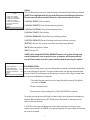
Introduction
Congratulations on the purchase of your new High Speed Dome Camera. This camera
is a full-functional, high-speed pan-tilt-zoom camera in a compact size, enclosed in
a dome housing. It is designed for professional surveillance applications, and can be
integrated into any surveillance system.
Construction:
• Aluminum-Alloy housing and finishing
• High-precision, machined aluminum construction
• Designed for 24-7 operation
• Stepless and smooth PTZ with micro-processor controlled high-precision mechanism
• 360˚ endless pan range with 1˚-160˚ per second
• 90˚ Tilt range with 1˚-90˚ per second and auto flip
• Stabilized image transfer at 1˚/s (max. zoom)
Built-in Camera:
• High-Performance zoom camera with digital signal processing
• High-Resolution with real 540TVL
• High-Sensitivity with SONY Ex-View CCD
• Integrated 10x optical high-speed zoom iris lens
• Auto-Iris function
• Fast auto-focus
• Manually configurable exposure modes
• Privacy masking up to 24 zones
Functions:
• 128 preset points
• 4 preset tour sequences with 32 presets each
• 4 self-learning (pattern) sequences
• 1 scan sequence
• OSD for configuration setup
• RS 485 interface
• Multiple Protocol settings (CLINTON, Pelco-D, Pelco-P)
• Soft-Setup for ID, Baudrate, and Protocol
• Intelligent Thermal-Control with temperature indicator
• Idle-Protection with user definable action
4
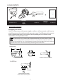
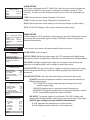
PACKAGE CONTENTS
DC 24VAC
Power
Supply
CE-PTZ10x Camera
Set Screw
(+1 extra)
Wall Mount
User Manual
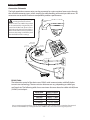
Installation and Set up
Unpacking your camera
Your PTZ camera comes with a power supply, as well as a wall mount and a small screw to
attach the camera to the wall mount (plus one extra screw). Carefully remove the contents
from it’s packing and set on a firm surface. Save the packing in case of future service
requirements or transportation needs.
The Transparent cover is sensitive and should be handled with care. Do not touch or rub the
surface in any way with the protective foil. Please use a dry cloth to clean the inner and outer
surfaces. For contamination, use a natural detergent. Improper cleaning method will cause permanent
scratches on the cover and cause unclear image or focusing errors of the camera.
Dimensions
9.8”
9.8”
3”
7”
Bolt
3”
4”
7”
Bolt
4”
Install the wall mount bracket
Install the wall mount bracket
Installation
Indoor Mounting
Indoor Mounting
Ceiling/Wall
Ceiling/Wall
Indoor mount bracket Indoor mount bracket
Set screw
Set screw
Insert PTZ tabs into mount
Insert PTZ tabs into mount
holes and turn to lock inholes
placeand turn to lock in place
5
Insert PTZ tabs into mount
Insert PTZ tabs into mount
holes and turn to lock inholes
placeand turn to lock in place
Precautions
For all service or installation needs, please refer to qualified service personnel or system installers
Do not attempt to disassemble the device
To prevent electric shock, do not remove screws or cover. There are no user-serviceable parts inside.
Contact qualified service personnel for maintenance
Handle the device with care
Do not strike or shake, as this may damage the device. It should be protected against extreme pressure,
vibration, and humidity during transportation and storage. Damages caused by improper transportation
may void the warranty.
Do not use strong or abrasive detergents when cleaning the device’s body and transparent cover.
Use a dry cloth to clean the device when dirty. When dirt is hard to remove, use a mild detergent and
wipe gently.
Do not operate the device beyond its specified temperature or humidity ratings.
Do not use the dome camera in an extreme environment where high temperature or high humidity
exists.
Do not point the camera lens directly into sunlight or any strong light source.
This will cause permanent damage to the camera and voids the warranty.
Read this user manual carefully before operating the device
Make sure local electric safety standards are followed when using or installing the appliance.
Do not install the camera in an orientation other than as designed
And do not bend or squeeze the device as this may damage the mechanical structure of the device and
void the warranty.
Do not touch the cover with bare hands or any object
Doing so may scratch the surface and affect the image quality.
6
WARNING
TO REDUCE THE RISK OF ELECTRIC SHOCK OR FIRE, SO NOT EXPOSE THIS PRODUCT TO RAIN
OR MOISTURE. DO NOT INSERT ANY METALLIC OBJECTS THROUGH THE VENTILATION GRILLS
OR OTHER OPENINGS ON THE EQUIPMENT.
This symbol indicates that dangerous voltage
constituting a risk of electric shock is present
within this unit.
This symbol indicates that there are important
operating and maintenance instructions in the
literature accompanying this unit.
FCC COMPLIANCE STATEMENT
FCC INFORMATION: THIS EQUIPMENT HAS BEEN TESTED AND FOUND TO COMPLY WITH
THE LIMITS FOR A CLASS A DIGITAL DEVICE, PURSUANT TO PART 15 OF THE FCC RULES.
THESE LIMITS ARE DESIGNED TO PROVIDE REASONABLE PROTECTION AGAINST HARMFUL
INTERFERENCE WHEN THE EQUIPMENT IS OPERATED IN A COMMERCIAL ENVIRONMENT.
THIS EQUIPMENT GENERATES, USES, AND CAN RADIATE RADIO FREQUENCY ENERGY AND, IF
NOT INSTALLED AND USED IN ACCORDANCE WITH THE INSTRUCTION MANUAL MAY CAUSE
HARMFUL INTERFERENCE TO RADIO COMMUNICATIONS. OPERATION OF THIS EQUIPMENT
IN A RESIDENTIAL AREA IS LIKELY TO CAUSE HARMFUL INTERFERENCE IN WHICH CASE THE
USER WILL BE REQUIRED TO CORRECT THE INTERFERENCE AT HIS OWN EXPENSE.
CAUTION: CHANGES OR MODIFICATIONS NOT EXPRESSLY APPROVED BY THE PARTY
RESPONSIBLE FOR COMPLIANCE COULD VOID THE USERS AUTHORITY TO OPERATE THE
EQUIPMENT.
CE COMPLIANCE STATEMENT
WARNING: THIS IS A CLASS A PRODUCT. IN A DOMESTIC ENVIRONMENT, THIS PRODUCT
MAY CAUSE RADIO INTERFERENCE IN WHICH CASE THE USER MAY BE REQUIRED TO TAKE
ADEQUATE MEASURES.
CAUTION: BEFORE ATTEMPTING TO CONNECT OR OPERATE THIS PRODUCT, PLEASE READ THE
LABEL ON THE BOTTOM AND USER’S MANUAL CAREFULLY.
Technical specifications are subject to change without prior notice. Manual may contain
mistakes or print errors. All trademarks mentioned belong to their respective owners.
7
Installation
Safety Instructions before starting
- Do not install and operate this appliance in a flammable and explosive environment.
- Make sure that the installation is done according to the local electricity safety regulations of your country.
- Before installation and maintenance, make sure that the appliance is disconnected from the power source.
- Handle the device during installation carefully. Falls or extreme vibration may cause irreparable damages or void the warranty.
- Do not install or operate the device near any high-voltage devices or high-voltage cable. The safety distance should remain at least 50m.
- To achieve best image quality, its recommended to use underground cable shielded with steel tube. Do not install the cable without any protection.
- In a thunderstorm area or region with high inductive voltage, such as high voltage transformer stations, it is necessary to use additional lightning-proof equipment or
lightning rod for protection.
- For outdoor installation, lightning-proof and grounding of the device should be considered. Please refer to the industrial safety regulations of your country.
- Grounding should be considered to eliminate any interference and fulfill the safety requirements. Do not connect the ground with short-circuited or other high voltage electric networks.
- The resistance of down conductor should not exceed 4 Ohms, and its thickness should be
at least 25mm2.
- This appliance has the lightning-proof function which can prevent damages caused by high-voltage pulse, such as lightning strike below 1500.
- This device meets the Ip66 standards against dust and water. Make sure that the installation is protected from prolonged water droplet/spatter exposure, which can damage the device.
- Make sure that the installation environment meets the requirements of the device, such as weight support, sufficient room for cords, and power supply requirements.
8
Installation
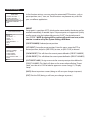
Connection Schematic
The high speed dome camera series can be connected to various optional accessories through
the standard connector types, which simplify the cable handling and avoids possible errors. All
accessories are tested for maximum compatibility and best performance.
This dome has jumperless design, meaning protocol, baud-rate,
and ID are to be set in OSD. The protocol
can be automatically recognized by the
system. For the first start, please ensure
your keyboard parameters match those
shown on the initial screen (ie. protocol,
baud-rate, ID). Doing so will allow you to
enter the OSD for further settings.
321
0X
CE-PTZ1
Tx
>
4<01 oard
VER3 Keyb
em
Syst
T/
)
lack Wire
AC24V (B
ed Wire)
AC24V (R
DVR
ection
BNC Conn DVR
r or
to Monito
MENU
MUX
PA
AUTO
S
/
NEXT
PREV
/
HOLD
SE/
CLO L
DE
R
RS2322 G
RS23 DC12V RS485
Adaptor
rd 5)
Keyboa
(No: 1437
RS-232/R T
GND GND
+
RS485
+
DC12V
+
DC12V T
RS232
CAM
2
6
CLR
4
Power
9
8
R
ENTE
7
RJ45
0
Keyboard
*
ble
EY
CE-PTZK
RJ45 Ca
daptoY)r
board A
Key
(included
E/
TELDn
Pg
N
3
5
RS-485/
/
NEAR.F
PIC
MO
AUX/
1
DC12V
ZOOM
FOCU
IRIS
/
RUN/
/
WIDE
PgUp
/
FAR .L
PIC
/
OPEN
BACK
N/
ON/
ALM/
SYS
MUX
DVR
OFF/
GRP/
ire)
(Green W )
RS485+
Wire
(Yellow
RS485-
Rx
R
POWE
/
SHOT
SE
TZKE
with CE-P
l Outlet
ly to Wal
pp
Power Su
VR or M
BNC to D
onitor
l Outlet
ly to Wal
pp
Power Su
r
Monito
DVR
DVR
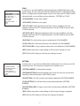
RS485 CableThe telemetric control of the device uses RS485 serial communication with half duplex
transmission technology. The transmission distance can vary, depending on cable type,
and baud rate. The following table shows maximum distances based on cable with 0,56mm
(24AWG) twisted pair:
Baud Rate
2400 bps
4800 bps
9600 bps
19200 bps
Max. Distance
5577ft / 1700m
3609ft / 1100m
2297ft / 700m
1312ft / 400m
Due to environmental interfaces, such as electromagnetic and induction fields, or number of connected
devices on the RS485 bus, or using thinner than 24AWG cable, the transmission range may be less.
9
Installation
Star-ConnectionThe star-form connection is most commonly used. It enables the connection of different dome
cameras with longer cable runs. It is recommended to use an RS485 distributor to ensure the
telemetric data transmission.
RS 485+
RS 485-
>
4<01 oard
VER3 Keyb
em
Syst
The advantage of the star-connection is that every channel can work independently and can
take a cable length up to 3,280 feet (1000 meters) (depending on cable quality). In cases where
more dome cameras are installed, the star-connection can be extended with additional RS485
distributors.
Termination ON
Termination ON
Termination OFF
Termination OFF
>
4<01 oard
VER3 Keyb
em
Syst
RS 485+
RS 485+
RS-485 Distributor
RS 485-
RS 485>
4<01 oard
VER3 Keyb
em
Syst
>
4<01 oard
VER3 Keyb
em
Syst
Monitor
(optional)
Up to 750m, coaxial cable
Video CableVideo Amplifier (optional)
Coaxial cable with 75Ω impedance with copper conductor at center conductor, and shielded
with 95% copper. The following table shows different cable type and its maximum length:
Termination ON
Termination ON
Cable Standard
RG 6 / U
DVR
(optional)
The values are for reference only. Depends on the cable
quality and environmental conditions, the transmission
Balun Receiver
distance
might be less.
(optional)
DVR
750 ft / 229m
Balun Transmitter
1000 ft /
(optional)
RG 11 / U
Termination ON
Termination OFF
Termination OFF
Max. Distance (m / ft)
RG 59 / U
Termination ON
Termination OFF
Termination OFF
305m
Monitor
(optional)
1500 ftUp/ to
457m
1200m, twisted pair or cat5 cable
If the cable length is more than 1,312ft (400m), it is recommended to use optional accessories,
RS-485 Distributor
such as a video amplifier or twisted-pair video converter,
for boosting the video signal.
RS-485 Distributor
>
4<01 oard
VER3 Keyb
em
Syst
RS 485+
120Ω
Resistor
120Ω
Resistor
>
4<01 oard
VER3 Keyb
em
Syst
RS 485-
DVR
(optional)
DVR
Device 1
Device 2
Device 3
Up to 750m, coaxial cable
Extend connection distance
with video amplifier
Up to 750m, coaxial cable
Video Amplifier (optional)
Video Amplifier (optional)
Monitor
(optional)
Monitor
(optional)
DVR
(optional)
DVR
(optional)
DVR
DVR
Balun Transmitter
Balun Receiver
(optional)
(optional)
Balun Transmitter
Balun Receiver
(optional) Up to 1200m, twisted pair or cat5 cable (optional)
Extend connection distance with
Twisted-Pair video converter
Monitor
(optional)
Monitor
(optional)
Up to 1200m, twisted pair or cat5 cable
RS 485+
120Ω
Resistor
120Ω
Resistor
RSRS
485+
485-
120Ω
Resistor
120Ω
Resistor
RS 485-
Device 1
Device 2
Device 3
DVR
(optional)
DVR
(optional)
DVR
DVR
Device 1
10
Device 2
Device 3
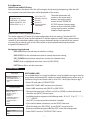
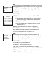
Basic OperationInitial Screen and Self-Testing
After powered on, the dome starts the self-testing by slowly rotating and panning. After the selftest completes the initial information will be displayed on the screen.
S/N:XXXXXXXXXXXXXXX
CLINTON V2.42
PROTOCOL: CLINTON
DOME ADDRESS: 001
COMM 9600, N, 8, 1
S/N of the PTZ
Software Version
Protocol
Dome ID
Communication
Parameter
The initial information will
remain on the screen until a
button is pressed, joystick is
moved, or until “POWER UP
ACTION” initiates. See next page
on how to show Initial Info within
system settings menu, and how
to define Power up action.
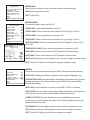
Open the On-Screen-Display (OSD) Menu
This dome supports OSD menu for simple configuration of device settings. To enter the OSD
menu, press [shot] 95 [enter] on the keyboard. Or call the sequence [shot] 9 [enter] twice within 3
seconds. If you encounter troubles, make sure your keyboard settings are correct for the camera
you are trying to control, such as the CAM number on your keyboard matching the number
assigned to the desired PTZ.
Navigation from keyboard
[IRIS OPEN] Enters the sub menu or confirms a setting
[IRIS CLOSE] Exits the selected menu item or cancels the current setting.
[UP], [DOWN] Move between menu lines, or adjust the selected value.
[RIGHT] Enter a highlighted menu item. (same as [IRIS OPEN])
[LEFT] Moves left or exit the menu item.
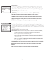
System Settings
MAIN MENU
-----------------SYSTEM SETTING -->
CAMERA SETTING -->
FUNCTION SETTING -->
WINDOW BLANKING -->
EXIT
SYSTEM SETTING
-----------------EDIT DOME LABEL -->
INITIAL INFO -->
DISPLAY SETUP -->
MOTION -->
CLEAR -->
PASSWORD SETUP -->
CLOCK SETTING -->
COMM SETTING -->
BACK
EXIT
EDIT DOME LABEL
-----------------LABEL: DOME 1
BACK
EXIT
EDIT DOME LABEL
For multiple domes in a single installation, it may be helpful to assign a name to
every dome with location info. Label may contain alphanumeric values up to 16
characters long. Ensure Dome Label is set to “ON” ; see Display Setup on pg.12.
- Enter OSD and select SYSTEM SETTING
- Select EDIT DOME LABEL and enter the sub menu
- Select LABEL and enter with [RIGHT] or [IRIS OPEN]
- The input character starts to flash, use [UP] or [DOWN] to select the desired character and [RIGHT] for next input.
- Available characters appear in the following order: “0” to “9”, “A” to “Z”, “:” , “<” , “>” , “-”, {SPACE}
- Use [LEFT] to move to previous character if needed.
- If you need to delete a character, use the {SPACE} character.
- When finished, press [IRIS OPEN] , or use [RIGHT] to move to last character and then navigate to BACK or EXIT to exit the editing mode.
- Select “BACK” to exit to “SYSTEM SETTING” menu.
11
INITIAL INFO
-----------------S/N: XXXXXXXXXXXXXXX
CLINTON V2.42
PROTOCOL: CLINTON
DOME ADDRESS: 001
COMM 9600, N, 8, 1
BACK
EXIT
DISPLAY SETUP
--------------DOME LABEL
PRESET LABEL ZOOM LABEL
ZONE LABEL DIRECTION LABEL
TEMPERATURE LABEL
TIME LABEL DATE LABEL BACK
EXIT
DOME LABEL
PRESET LABEL
INITIAL INFO
Shows the serial number, current firmware version and other settings.
[BACK]: Move to previous screen
[EXIT]: Exit the OSD
DISPLAY SETUP
Customize the labels shown on the OSD
--OFF
OFF
OFF OFF
OFF
OFF
OFF
OFF
TEMP
[DOME LABEL]: Shows dome label name on OSD
[PRESET LABEL]: Shows the current preset label on OSD (see pg.15; “Preset”)
[ZOOM LABEL]: Shows magnification setting on OSD
[ZONE LABEL]: Shows current zone (must first be set up: see pg.17; “Zones”)
[DIRECTION LABEL]: Shows current direction on OSD: Displayed as (Pan: 0º-359º,
Tilt: 0º-90º)
[TEMPERATURE LABEL]: Shows current temperature inside dome on OSD
[TIME LABEL]: Shows current time on OSD. Displayed as Year/Month/Day.
ZONE LABEL
DIRECTION
ZOOM
DATE
TIME
[DATE LABEL]: Shows current date on OSD. Displayed as 24 hour clock.
[BACK]: Move to previous screen (doing so will save your changes to display setup)
[EXIT]: Exit the OSD (doing so will save your changes to display setup)
MOTION
-----------------AUTO FLIP
OFF
PROPORTION PAN
OFF
PARK TIME
000 PARK ACTION
NONE
POWER UP ACTION NONE
FAN ENABLED
113
BACK
EXIT
MOTION
The motion control includes the setting for Park Time action and other features.
[AUTO FLIP]: Disabling this function will limit the tilt range to 90 degrees only
[PROPORTIONAL PAN]: Pan speed adjusts accordingly to the zoom ratio. The more
the operator zooms in, the slower the pan speed. The Park Time speed will be
adjusted accordingly.
[PARK TIME]: Sets the idle time in minutes, until [PARK ACTION] is activated.
[PARK ACTION]: You can select an action that will be started after certain idle time,
such as preset, tour or pattern. Select NONE to disable the function.
[POWER UP ACTION]: Instructs the dome to start a predefined action when
system boots up and completes the self test. This could be helpful to restore the
observation after power loss.
[FAN ENABLED]: Sets the temperature limit for the internal cooling fan to start.
[BACK]: Move to previous screen (doing so will save your changes to motion)
[EXIT]: Exit the OSD (doing so will save your changes to motion)
12
CLEAR
-----------------CLEAR ALL ZONES
CLEAR ALL PRESETS
CLEAR ALL PATTERNS
CLEAR ALL TOURS
CLEAR ALL WINDOWS
FACTORY DEFAULTS
RESTART
BACK
EXIT
CLEAR
The CLEAR function resets the stored settings and controls back to factory default.
*NOTE: Pressing Right with the joystick will activate the following functions.
There are no sub menus to these functions. You cannot undo the action.
[CLEAR ALL ZONES]: Clear set zones
[CLEAR ALL PRESETS]: Clear all stored preset positions
[CLEAR ALL PATTERNS]: Clear all stored pattern tours
[CLEAR ALL TOURS]: Clear all tours
[CLEAR ALL WINDOWS]: Clear all privacy masking settings
*[FACTORY DEFAULTS]: Reset all settings and return to factory settings
[RESTART]: Restarts the system, used after resetting factory defaults
[BACK]: Move to previous screen
[EXIT]: Exit the OSD
*NOTE: After using the FACTORY DEFAULTS option, all system settings and
stored information, such as presets, tour, or patterns will be permanently
erased. Please make sure this is your intention before selecting this option.
PASSWORD SETUP
-----------------OLD PASSWORD : ******
NEW PASSWORD : ******
CONF PASSWORD: ******
ENABLE PASSWORD
OFF
BACK
EXIT
PASSWORD SETUP
In password-settings menu, you can change the password, and enable/disable the
password protection function. The password function can prevent unauthorized
access to the OSD and changes to the settings. It consists of a 6 digit number from
0-9, and can be disabled if so desired.
1. To modify the password, you must input the old password. The default password is 000000.
2. Enter a new password.
3. Enter the new password again in [CONF PASSWORD] to confirm.
To set the password, move left/right to select a digit, and up/down to change the
number. When finished, press [IRIS OPEN] on the keyboard, or move the cursor
right to save the settings.
A “SUCCESS” message will appear on screen when changes are saved, or your
submission is correct. An “ERROR” message will appear on screen when an incorrect
password is entered.
13
CLOCK SETTING
-----------------TIME
13:44:30
DATE
10/03/31
BACK
EXIT
CLOCK SETTING
The system is equipped with a RTC (Real-Time Clock) and can be used to display the
date/time information on the screen, or operated via schedule (see pg.18; “Time
Running”). In order to use this function correctly, you must first set up the date and
time.
[TIME]: Change the time setting. Displayed as 24hr clock.
[DATE]: Change the date setting. Displayed as Year/Month/Day.
[BACK]: Move to previous screen (doing so will save your changes to clock setting)
[EXIT]: Exit the OSD (doing so will save your changes to clock setting)
COMM SETTING
-----------------S/N: XXXXXXXXXXXXXXX
CONF:XXXXXXXXXXXXXXX
SITE ID
001
COMM SPEED 9600bps PROTOCOL
CLINTON
BACK
EXIT
Camera Settings
MAIN MENU
-----------------SYSTEM SETTING -->
CAMERA SETTING -->
FUNCTION SETTING -->
WINDOW BLANKING -->
EXIT
CAMERA SETTING
-----------------ZOOM SPEED
HIGH
DIGITAL ZOOM
ON
BLC MODE
OFF
SLOW SHUTTER
OFF
ADVANCE SETTING -->
BACK
EXIT
CAMERA SETTING
-----------------ZOOM SPEED
HIGH
DIGITAL ZOOM
ON
BLC MODE
OFF
SLOW SHUTTER
OFF
ADVANCE SETTING -->
BACK
EXIT
ADVANCE SETTING
-----------------AE MODE
AUTO
SHUTTER
N/A
IRIS
N/A
BRIGHT
N/A
WB MODE
AUTO
R GAIN
N/A
B GAIN
N/A
BACK
EXIT
COMM SETTING
To edit settings for Site ID, baudrate, and protocol, you must first unlock these settings
by entering the serial number again into the [CONF] field. Protocol setting can be
detected automatically.
In this section, the camera and image related functions can be set.
[ZOOM SPEED]: Zoom-in speed
[DIGITAL ZOOM]: Besides the optical zoom, this PTZ is equipped with digital image
enlargement, known as digital zoom. When off, only the optical zoom will be available.
[BLC MODE]: Backlight compensation mode. Use this option when the observed
object has a strong backlight such as sunlight, or other light source.
[SLOW SHUTTER]: The slow shutter allows a higher sensitivity by exposing the image
sensor a longer period of time, useful when observing objects do not have much
movement.
[ADVANCED SETTING]: Enters the advanced settings sub-menu for the camera.
[AE MODE]: Activate auto-exposure mode for various exposure methods for different environments:
- SHUTTER MODE: In shutter mode, the camera changes the shutter speed to regulate light.
- IRIS MODE: Regulate the iris-opening to control the exposure.
- BRIGHTNESS: Regulate the exposure by changing the brightness control
- AUTO: Automatically regulates the exposure modes.
[WB MODE]: The camera supports Auto, Manual, ATW, OPW, Outdoor, and Indoor modes of White Balance, which chooses the correct color of the image. *NOTE: R gain and B gain are only editable in Manual mode.
- R GAIN: Regulates the red elements in the image color
- B GAIN: Regulates the blue elements in the image color
14
Function Settings
MAIN MENU
-----------------SYSTEM SETTING -->
CAMERA SETTING -->
FUNCTION SETTING -->
WINDOW BLANKING -->
EXIT
FUNCTION SETTING
-----------------PRESETS -->
SCAN -->
PATTERNS -->
TOUR -->
ZONES -->
TIME RUNNING -->
BACK
EXIT
PRESETS
-----------------PRESET NUMBER
001
SET PRESET -->
SHOW PRESET
CLEAR PRESET
EDIT PRESET LABEL -->
BACK
EXIT
In the function settings, user can setup the automated PTZ functions, such as
preset position, tours, scan, etc. These functions may become very useful for
your surveillance application.
PRESET
Preset point is a position of PTZ which can be memorized by the device and be
recalled immediately, if needed. Up to 128 preset points are supported. Quickly
recall a preset using the keyboard by pressing “SHOT”, the desired preset #,
then “ENTER”. *NOTE: Assigning #95 to a preset will result in an error, as this
number is used to call up the System Settings OSD Menu.
[PRESET NUMBER]: Selected preset position
[SET PRESET]: Setup the preset position. Enter this menu, move the PTZ to
desired position, and press [IRIS OPEN] to store, or [IRIS CLOSE] to discard.
[SHOW PRESET]: This will show the current preset defined in [PRESET NUMBER]
[CLEAR PRESET]: This will delete the current preset defined in [PRESET NUMBER]
[EDIT PRESET LABEL]: Assign a name to the current preset position defined in
[PRESET NUMBER]. This label will show on the screen when called up. “Preset
Label” must be set to “ON” for label to appear on-screen. See pg 12; “Display
Setup”.
[BACK]: Move to previous screen (doing so will save your changes to presets)
[EXIT]: Exit the OSD (doing so will save your changes to presets)
15
SCAN
-----------------SCAN NUMBER
01
SCAN SPEED
50
SET LEFT LIMIT -->
SET RIGHT LIMIT -->
CLEAR SCAN
RUN SCAN
EDIT SCAN LABEL -->
BACK
EXIT
SCAN
A Scan-Tour is an automated Pan movement between 2 defined positions with
speed setting. The scan will move from the defined Left limit, to the defined Right
limit in a straight path, and back again. If you wish to have your PTZ follow a more
advanced path, use one of the next two selections: “PATTERN”, or “TOUR”.
[SCAN NUMBER]: Current scan number
[SCAN SPEED]: Define the scan speed
[SET LEFT LIMIT]: Define the left point of the scan tour. To define, enter the
selection and move the PTZ to desired position. Use [IRIS OPEN] to store or [IRIS
CLOSE] to discard.
[SET RIGHT LIMIT]: Define the right point of the scan tour. To define, enter the
selection and move the PTZ to desired position. Use [IRIS OPEN] to store or [IRIS
CLOSE] to discard.
[RUN SCAN]: This will run the current scan defined in [SCAN NUMBER]
[CLEAR SCAN]: This will erase the current scan defined in [SCAN NUMBER]
[EDIT SCAN LABEL]: Assign a name to the current scan defined in [SCAN NUMBER]
[BACK]: Move to previous screen (doing so will save your changes to scan)
[EXIT]: Exit the OSD (doing so will save your changes to scan)
PATTERNS
-----------------PATTERN NUMBER
001
PROGRAM PATTERN -->
RUN PATTERN
CLEAR PATTERN
EDIT PATTERN LABEL -->
BACK
EXIT
PATTERN
A pattern-tour is a custom tour defined by recording the user’s actions up to 180
seconds per tour. This camera can support up to 4 pattern tours.
[PATTERN NUMBER]: Current pattern number
[PROGRAM PATTERN]: Record the pattern tour. Enter this menu to start the tour
recording, when finished, press [IRIS OPEN] to store.
[RUN PATTERN]: This will run the current pattern defined in [PATTERN NUMBER]
[CLEAR PATTERN]: This will erase the current pattern defined in [PATTERN
NUMBER]
[EDIT PATTERN LABEL]: Assign a name to the current pattern defined in [PATTERN
NUMBER]
[BACK]: Move to previous screen (doing so will save your changes to pattern)
[EXIT]: Exit the OSD (doing so will save your changes to pattern)
16
TOUR
-----------------TOUR NUMBER
001
EDIT TOUR -->
RUN TOUR
CLEAR TOUR
BACK
EXIT
TOUR
A Tour is an automated cruising through selected preset positions with individual
speed settings and dwell times. This PTZ supports up to 4 tours with 24 positions
each. *NOTE: Before a tour can be properly set up, you must first define your
preset points you wish to include in the tour (see page 16 “Presets”).
A tour sequence will repeat until interrupted by a movement of the joystick
after it reaches a preset point, or until another command is entered (ie.
[SHOT]95[ENTER] to enter menu).
[TOUR NUMBER]: Current tour number
EDIT TOUR
PO-S-TM PO-S-TM PO-S-TM
00-0-00 00-0-00 00-0-00
00-0-00 00-0-00 00-0-00
00-0-00 00-0-00 00-0-00
00-0-00 00-0-00 00-0-00
00-0-00 00-0-00 00-0-00
00-0-00 00-0-00 00-0-00
00-0-00 00-0-00 00-0-00
00-0-00 00-0-00 00-0-00
BACK
EXIT
[EDIT TOUR]: Edit the current selected tour as defined in [TOUR NUMBER]
Tour Editing:
PO: The preset position being included in the tour. If there is no preset position stored, please exit, and define presets before continuing.
S: The speed in which the PTZ moves to this preset. The value is between 1(slow)-8(fast).
TM: The dwell time before the PTZ moves to the next point. Given in seconds. (Up to 60 sec.)
[RUN TOUR]: This will run the current tour defined in [TOUR NUMBER]
[CLEAR TOUR]: This will erase the current tour defined in [TOUR NUMBER]
[BACK]: Move to previous screen (doing so will save your changes to tour)
[EXIT]: Exit the OSD (doing so will save your changes to tour)
ZONES
-----------------ZONE NUMBER
001
SET LEFT LIMIT -->
SET RIGHT LIMIT -->
CLEAR ZONE
EDIT ZONE LABEL -->
BACK
EXIT
ZONES
The zone function allows user to define a perimeter with a name tag. The
perimeter is defined by setting a Left, and Right end of a desired area. When the
camera enters this area, the name will be displayed on the screen, which provides
better orientation in surveillance applications. Up to 8 zones are supported. Make
sure “Zone Label” is set to “ON” in Display Setup; see pg12.
[ZONE NUMBER]: Current zone number
[SET LEFT LIMIT]: Define the left point of the zone
[SET RIGHT LIMIT]: Define the right point of the zone
[CLEAR ZONE]: This will erase the current zone defined in [ZONE NUMBER]
[EDIT ZONE LABEL]: Assign a name to the current zone defined in [ZONE NUMBER]
[BACK]: Move to previous screen (doing so will save your changes to zones)
[EXIT]: Exit the OSD (doing so will save your changes to zones)
17
TIME RUNNING
-----------------TIME CHANNEL
1
START TIME
00:00
END TIME
00:00
RUNNING
NONE
BACK
EXIT
TIME RUNNING
The time running function is a scheduled start for predefined action, such as preset
tour, scan tour, etc. This PTZ supports up to 4 schedules. Before setting this function,
please make sure that the system time has been set correctly (see clock setting; pg14)
[TIME CHANNEL]: Current schedule number
[START TIME]: Start time of selected schedule as defined in [TIME CHANNEL]
[END TIME]: End time of selected schedule as defined in [TIME CHANNEL]
[RUNNING]: Define the action to be started. Select None to deactivate the function.
[BACK]: Move to previous screen (doing so will save your changes to time running)
[EXIT]: Exit the OSD (doing so will save your changes to time running)
Window Blanking
WINDOW BLANKING
-----------------WINDOW NUMBER
01
EDIT WINDOW -->
ENABLE WINDOW
ON
CLEAR WINDOW
BACK
EXIT
The Window Blanking function is used to protect the privacy in the observed area, as
this may be required by law for certain applications. It is also known as “Privacy Masking”,
which covers the selected area with a blank window. This PTZ supports up to 25 masking
windows.
[WINDOW NUMBER]: Current window number
[EDIT WINDOW]: Edit the current masking window as defined in [WINDOW NUMBER]
1. Center the area you wish to mask on the screen by using the joystick.
2. Press iris open to enter window blanking edit.
3. Use the [UP], and [DOWN] movements to increase or decrease the height of the window mask. 4. Use [LEFT], or [RIGHT] to decrease or increase the width of the window mask.
5. Press [IRIS OPEN] to save the mask.
[CLEAR WINDOW]: Clear the current masking window as defined in [WINDOW NUMBER]
[BACK]: Move to previous screen (doing so will save your changes to time window
blanking)
[EXIT]: Exit the OSD (doing so will save your changes to window blanking)
18
MAIN MENU
-----------------SYSTEM SETTING -->
CAMERA SETTING -->
FUNCTION SETTING -->
WINDOW BLANKING -->
EXIT
OSD Map
OSD MENU INDEX
SYSTEM SETTING
-----------------EDIT DOME LABEL -->
INITIAL INFO -->
DISPLAY SETUP -->
MOTION -->
CLEAR -->
PASSWORD SETUP -->
CLOCK SETTING -->
COMM SETTING -->
BACK
EXIT
CAMERA SETTING
-----------------ZOOM SPEED
HIGH
DIGITAL ZOOM
ON
BLC MODE
OFF
SLOW SHUTTER
OFF
ADVANCE SETTING -->
BACK
EXIT
ADVANCE SETTING
-----------------AE MODE
AUTO
SHUTTER
N/A
IRIS
N/A
BRIGHT
N/A
WB MODE
AUTO
R GAIN
N/A
B GAIN
N/A
BACK
EXIT
EDIT DOME LABEL
-----------------LABEL: DOME 1
BACK
EXIT
INITIAL INFO
-----------------S/N: XXXXXXXXXXXXXXX
CLINTON V2.42
PROTOCOL: CLINTON
DOME ADDRESS: 001
COMM 9600, N, 8, 1
BACK
EXIT
PRESETS
-----------------PRESET NUMBER
001
SET PRESET -->
SHOW PRESET
CLEAR PRESET
EDIT PRESET LABEL -->
BACK
EXIT
SCAN
-----------------SCAN NUMBER
01
SCAN SPEED
50
SET LEFT LIMIT -->
SET RIGHT LIMIT -->
CLEAR SCAN
RUN SCAN
EDIT SCAN LABEL -->
BACK
EXIT
DISPLAY SETUP
-----------------DOME LABEL
OFF
PRESET LABEL OFF
ZOOM LABEL
OFF
ZONE LABEL OFF
DIRECTION LABEL
OFF
TEMPERATURE LABEL OFF
TIME LABEL OFF
DATE LABEL OFF
BACK
EXIT
PATTERNS
-----------------PATTERN NUMBER
001
PROGRAM PATTERN -->
RUN PATTERN
CLEAR PATTERN
EDIT PATTERN LABEL -->
BACK
EXIT
MOTION
-----------------AUTO FLIP
OFF
PROPORTION PAN
OFF
PARK TIME
000
PARK ACTION
NONE
POWER UP ACTION NONE
FAN ENABLED
113
BACK
EXIT
TOUR
-----------------TOUR NUMBER
001
EDIT TOUR -->
RUN TOUR
CLEAR TOUR
BACK
EXIT
CLEAR
-----------------CLEAR ALL ZONES
CLEAR ALL PRESETS
CLEAR ALL PATTERNS
CLEAR ALL TOURS
CLEAR ALL WINDOWS
FACTORY DEFAULTS
RESTART
BACK
EXIT
ZONES
-----------------ZONE NUMBER
001
SET LEFT LIMIT -->
SET RIGHT LIMIT -->
CLEAR ZONE
EDIT ZONE LABEL -->
BACK
EXIT
PASSWORD SETUP
-----------------OLD PASSWORD : ******
OLD PASSWORD : ******
OLD PASSWORD : ******
ENABLE PASSWORD
OFF
BACK
EXIT
TIME RUNNING
-----------------TIME CHANNEL
1
START TIME
00:00
END TIME
00:00
RUNNING
NONE
BACK
EXIT
PASSWORD SETUP
-----------------OLD PASSWORD : ******
OLD PASSWORD : ******
OLD PASSWORD : ******
ENABLE PASSWORD
OFF
BACK
EXIT
COMM SETTING
-----------------S/N: XXXXXXXXXXXXXXX
CONF:XXXXXXXXXXXXXXX
SITE ID 001
COMM SPEED 9600bps
PROTOCOL
CLINTON
BACK
EXIT
FUNCTION SETTING
-----------------PRESETS -->
SCAN -->
PATTERNS -->
TOUR -->
ZONES -->
TIME RUNNING -->
BACK
EXIT
19
WINDOW BLANKING
-----------------WINDOW NUMBER
01
EDIT WINDOW -->
ENABLE WINDOW
ON
CLEAR WINDOW
BACK
EXIT
EDIT PRESET LABEL
-----------------LABEL: PRESET-001
BACK
EXIT
EDIT SCAN LABEL
-----------------LABEL: AUTOSCAN1
BACK
EXIT
EDIT PATTERN LABEL
-----------------LABEL: PATTERN1
BACK
EXIT
PO-S-TM
00-0-00
00-0-00
00-0-00
00-0-00
00-0-00
00-0-00
BACK
EXIT
EDIT TOUR
PO-S-TM PO-S-TM
00-0-00 00-0-00
00-0-00 00-0-00
00-0-00 00-0-00
00-0-00 00-0-00
00-0-00 00-0-00
00-0-00 00-0-00
ZONES
-----------------LABEL: ZONE-1
BACK
EXIT
Specifications
Model
CE-PTZ10X
Signal Format
PAL / NTSC
Scanning
Progressive
Image Sensor
1/4 inch Ex-View CCD
H. Resolution
540 TVL
Viewing Angle
46.0 º (Wide end)
4.6 º (Tele end)
Zoom
10 x Optical / 12 x Digital
Min. Illumination
1.0Lx (typical) - (F1.8, 50 IRE)
Focus
Auto / Manual
White Balance
Auto / Manual (ATW, Indoor, Outdoor, One Push WB, Manual WB)
Shutter Speed
1 to 1/10,000 Sec. 22 steps
Iris Control
Auto / Manual / Auto Slow Shutter
Gain Control
Auto / Manual (-3 to 28 dB, 2 dB steps)
Video Output
VBS: 1.0Vp-p (Sync Negative), Y / C Output
S/N Ratio
More than 50 dB
Pan Speed
0.4 º - 300 º per Sec.
Tilt Speed
0.4 º - 150 º per Sec.
Pan Range
360 º
Tilt Range
0 - 90 º
Communication
RS-485, multiple-protocol, coax
Preset Positions
128 Presets
Auto Pan
Tour / Sequence
Yes, between 2 presets
4 progr. Tours with max 32 presets / 4 Patterns up to 180s
Privacy Mask
Operating Temp.
24 Position / 8 Position per Screen
Outdoor: -40 ºF to 140ºF / Indoor: 14ºF to 122ºF
Power
DC 12V / AC 24V
If you have trouble operating your camera and the guidelines in this
manual do not enable you to solve the problem, contact Clinton
Electronics Technical Support at 1-800-549-6393 or 815-633-1444.
20
21
v.01.25.10