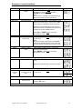
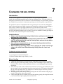
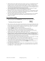
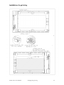
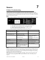
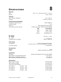
1
Atomic Colors
user manual
Atomic Colors Unit
Atomic 3000 DMX and Atomic Colors Unit combined.
© 2003 Martin Professional A/S, Denmark.
All rights reserved. No part of this manual may be reproduced,
in any form or by any means, without permission in writing from
Martin Professional A/S, Denmark.
Printed in Canada.
P\N 35000143, Rev. A
Atomic Colors User Manual
2
SAFETY INFORMATION.................................................. 4
INTRODUCTION ................................................................ 5
PREPARATION FOR USE ............................................... 6
MOUNTING THE UNIT ..................................................... 9
CONNECTING THE UNIT .............................................. 10
OPERATING THE UNIT ................................................. 14
CHANGING THE GEL STRING .................................... 20
SERVICE .......................................................................... 24
SPECIFICATIONS ........................................................... 25
Atomic Colors User Manual
3
SAFETY INFORMATION
1
Before using this unit please read this manual completely,
and refer to the user manual for Atomic 3000 DMX strobe.
Warning: This product is for professional use only!
It is not designed for household use.
This product is designed exclusively for use with the Martin Atomic 3000 DMX unit. Use the
device only as intended.
The Atomic 3000 DMX presents risks of lethal or severe injury due to fire and heat, electric
shock, ultraviolet radiation, and falls. Flashing light is also known to trigger epileptic seizures in
persons who are photosensitive. Please review the important safety information in the Atomic
3000 DMX user manual.
Read this manual before powering or installing the fixtures, follow the safety precautions listed
below and observe all warnings in this manual.
If you have questions about how to operate the fixtures safely, please contact your Martin dealer
or call the Martin 24-hour service hotline at +45 70 200 201.
Atomic Colors: Safety instructions.
General
•
•
•
Read this manual fully before starting to use the unit.
Ensure that no objects or items are near the front aperture, or can get trapped in the roller
mechanism.
Make sure the power supply for the Atomic Colors is connected and switched on, before
operating the Atomic strobe.
To guard against falls
•
•
•
•
•
When fitting the unit to the Atomic 3000DMX, ensure all screws are thoroughly re-tightened.
When rigging the unit, use the safety wire attached to the unit as a means of secondary
attachment.
Note: This safety wire is designed solely for use with the Atomic Colors unit. Use a
separate safety wire for Atomic 3000DMX strobe, and any other pieces of equipment.
When suspending the fixture above ground level, verify that the structure can hold at least 10
times the weight of all installed devices.
Verify that all external covers and rigging hardware are securely fastened and use an
approved means of secondary attachment such as a safety cable.
Block access below the work area whenever installing or removing the fixture.
To guard against epileptic seizure
•
•
•
Do not operate the fixture near stairways.
Provide advance notice that strobe lighting is in use.
Avoid extended periods of continuous flashing, particularly at frequencies of 10 to 20 flashes
per second, or with the color red.
Atomic Colors User Manual
Safety Information
4
2
INTRODUCTION
The Atomic Colors is a dedicated add-on unit for the Martin Atomic 3000 DMX strobe. This unit
enhances the versatility of the Atomic 3000 DMX by adding the extra dimension of color changes
that can be controlled and programmed with any standard DMX controller.
Color changing is achieved by moving (or scrolling) a string of colored ‘gels’ (theatrical grade,
plastic color media) in front of the strobe unit. A processor controlled, low voltage DC motor
drives the movement of the gel string, with the processor receiving instructions from a lighting
controller. The internal processor also determines the positions of the individual colors and
controls the speed of the cooling fans. The lighting controller can be any device that outputs the
widely used USITT DMX (1990) data protocol (‘DMX’), including the one that may already be
controlling your Atomic 3000 DMX strobe.
The Atomic Colors requires an external power supply that is not included. Standard scroller
power supplies are available in various unit sizes. Each Atomic Colors requires one unit of power.
The size of power supply required is dependant on how many Atomic Colors you are using. Eight
Atomic Colors, for example, can be driven with a standard 8-unit scroller power supply.
The scroller power supply combines the low voltage and the DMX data for the Atomic Colors in
a special four-wire cable with XLR-4 connectors. The Atomic Colors features a ‘through’ XLR-4
connector that allows multiple units to be connected in a ‘daisy-chain’ to a single external power
supply.
The unit comes supplied with a gel string installed. This gel string has 10 color filters joined
together with special high temperature tape, to form one continuous piece. The colors in this gel
string have been chosen to offer a wide choice of color and intensity, and various other gel strings
are also available from your dealer. Custom made gel strings can be supplied, to special order.
It is possible for the user to manufacture their own gel strings for use in the unit, although this
must be done with great care. Poorly constructed gel strings may contribute to the unit failing to
work properly.
Mounting the Atomic Colors unit onto the Atomic 3000 DMX strobe is easily achieved using
existing hardware from the Atomic DMX 3000, and a permanently fixed steel safety wire is
supplied for secondary attachment.
Atomic Colors User Manual
Introduction
5
PREPARATION FOR USE
3
Unpacking
The Atomic Colors comes with the following items:
•
•
•
5 M (16.4 ft) XLR-4 connecting cable
Standard gel string (factory installed)
User manual
The packing material protects the fixture during shipment; always use it to transport the fixture.
System overview
(Detailed connection diagrams are given in Section 5.)
Power supply
The Atomic Colors requires a separate external power supply. These are supplied separately and
come in various standard unit sizes. Each Atomic Colors requires one unit of power.
The Martin Atomic power supplies, MPU-02 and MPU-08 will function on any standard
worldwide voltage/frequency electrical supply.
You may need to attach a plug on the mains cable for power supply.
To install a plug on the mains lead
The mains lead must be fitted with a heavy-duty cord cap with ground connection. Consult a
qualified electrician if you have any doubts about proper installation.
Following the cord cap manufacturer’s instructions, connect the yellow and green wire to ground
(earth), the brown wire to live, and the blue wire to neutral. The table below shows some pin
identification schemes.
Wire
Brown
Blue
Yellow/green
Pin
Live
Neutral
Ground
Atomic Colors User Manual
Marking
“L”
“N”
Screw color
Yellow or brass
Silver
Green
Preparation for use
6
Control data
Any device that outputs the DMX512 (1990) data protocol (including the one that may already be
controlling your Atomic 3000 DMX strobe) can be used to control the Atomic Colors. ‘DMX’ is
an industry standard data protocol, which allows up to 512 channels to be controlled through one
serial data link. These 512 channels may be used by up to a maximum of 32 devices on only one
cable run by ‘daisy-chaining’ the devices together.
To work on the DMX system, each device is assigned a control address, also known as the start
channel, which is the first channel used by that device, to receive instructions from the controller.
The Atomic Colors uses 1, or 2 DMX channels depending on which control mode it is set for.
The first DMX channel (start channel) controls the movement of the gel string, and the second
channel, if selected, allows for remote control of the cooling fan speed. Details of the address
setting procedure are given in Section 6 of this manual.
Cables
The power supply combines the control data and low voltage power into one XLR-4 cable that is
then distributed to the fixture(s). One 5M (16.4 ft) XLR 4-pin cable is supplied with each fixture.
The power supply connects to the DMX data link with 3 or 5-pin XLR cables.
The type of cable used in this system has specific design requirements. Failure to use the correct
type of cable can lead to malfunctions and/or damage to the system. Further details about cable
construction are shown later in this section.
Atomic Colors User Manual
Preparation for use
7
XLR-4 Cable Construction
Notes:
•
•
•
•
It is very important to ensure that the drain wire from the cable shield is connected to both
XLR connector cases.
Damage will occur if power connections short to the data, ground, or shield connections.
When assembling XLR 4-pin cables, heat shrink should be used on each individual pin to
prevent short circuits. (See diagram below)
Please take care when constructing these cables. A high percentage of problems are a direct
result of poor cable construction.
Detail of connector wiring (typical)
The correct wiring between male and female connectors is ‘one to one’.
XLR-4
Connector
(Pin No.)
1
Ground (0 V)
2.50mm² (14 AWG)
2
Control data minus (-)
0.35mm² (22 AWG)
3
Control data plus (+)
0.35mm² (22 AWG)
4
24 VDC (+ve)
2.50mm² (14 AWG)
Chassis
Cable shield/Drain wire
0.25mm² (24 AWG)
Function
Atomic Colors User Manual
Minimum Cable size
Preparation for use
Twisted data pair, with foil
shield and drain wire.
(See above)
8
MOUNTING THE UNIT
1.
2.
3.
4.
5.
6.
4
Place the Atomic 3000 DMX unit so that it is resting on its bottom edge as shown below.
Using an 8mm AF wrench, carefully remove the lower, front, M5 ‘Taptite’ screws on sides of
the Atomic 3000 DMX.
Loosen the top, front M5 ‘Taptite’ screws so that they protrude 5-6mm.
Position the Atomic Colors in front of the strobe as shown with the top hooks resting on the
loose ‘Taptite’ screws. Align the lower front screw holes and replace the lower front screws.
Tighten all screws.
Rig Atomic 3000 DMX/Colors fixture and fasten the safety wires.
Note: The safety wire attached to the unit is designed solely for use with the Atomic
Colors unit. Use a separate safety wire for Atomic 3000DMX strobe.
Attaching the ‘Atomic Colors’ unit to the ‘Atomic 3000 DMX’ strobe.
(For clarity, only one side of the units are shown)
Atomic Colors User Manual
Mounting the unit
9
CONNECTING THE UNIT
5
System Connections
This section describes how to connect the Atomic Colors to your lighting system using a 2-unit or
an 8-unit external power supply.
Notes:
• Ensure the AC input power is switched off while you are connecting components of the
system.
• Do not connect the power supplies to any type of dimmer circuit.
• Before operating the Atomic strobe, make sure the power supply for the Atomic Colors is
connected, and switched on.
• When rigging the fixture and power supplies, use the safety wires as a means of secondary
attachment.
• When suspending the fixture above ground level, verify that the structure can hold at least 10
times the weight of all installed devices.
• Ensure that all cables are securely fixed and do not present a safety hazard of any sort.
MPU-02 / MPU-08 Power Supplies
The MPU-02 and MPU-08 power supplies are specifically designed for use with the Atomic
Colors. They are suitable for use with any 100-250 V, 50/60 Hz AC power supply, via an
IEC320/CEE 22 socket.
The MPU-02 is a small, compact unit that powers two Atomic Colors. It has an XLR-5 connector
for DMX input and an XLR-4 connector for the combined power/data output to the color
scroller(s).
The MPU-08 is a rugged, touring style unit for theatrical bar/truss mounting. It can power up to
eight Atomic Colors fixtures in 2 circuits of four. It provides XLR-5 input/through output sockets
for DMX data, and 2 sets of XLR-4 input/return sockets for combined LV power/DMX data.
Atomic Colors User Manual
Connecting the unit
10
MPU-02 Connection Procedure
1. Rig the combined Atomic 3000 DMX and Atomic Colors fixture in the desired position,
ensuring that you use the safety wire as a secondary means of attachment.
2. Connect the power/data output on the MPU-02 to the power/data input on the Atomic
Colors with an XLR-4 cable.
3. Connect the MPU-02 to the main data link using the XLR-5 input. You can, for example,
run a 5-pin XLR cable from the DMX output of an Atomic 3000 DMX to the input of the
power supply. For more information on building a data link, please refer to the Atomic
DMX 3000 user manual. Continue “daisy-chaining” the DMX link by connecting the 5pin DMX thru socket on the power supply to the next Atomic 3000 DMX, power supply,
or other fixture.
4. Connect a second Atomic Colors unit, if desired, to the first unit using the second XLR-4
socket and an XLR-4 cable.
5. Connect the MPU-02 and the Atomic 3000 DMX units to the AC supply.
Note: Before operating the Atomic strobe, make sure the power supply for the Atomic
Colors is connected, and switched on.
System connections using the MPU-02 power supply.
Atomic Colors User Manual
Connecting the unit
11
MPU-08 Connection procedure
Important Note: ‘Return’ lines
The MPU-08 is designed for use with larger quantities of Atomic Colors fixtures, and
in bigger installations where the cable runs a longer.
In order to reduce the voltage drop in these longer cable runs, an XLR-4 ‘Return’
cable must be installed in the system, so the cabling forms a continuous loop.
1. Rig the combined Atomic 3000DMX and Atomic Colors fixtures in their desired
positions, ensuring that you use the safety wire as a secondary means of attachment.
2. Connect your source of DMX data to the XLR-5 input socket on the front of the MPU-08.
3. Using an XLR-4 cable, connect the ‘out’ of ‘Power outlet 1’ on the MPU-08, to the XLR4 input on the Atomic Colors fixture #1.
4. Using another XLR-4 cable, connect the XLR-4 output of Atomic Colors fixture #1, to
the XLR-4 input on the Atomic Colors fixture #2.
5. Repeat step 4, until you have a maximum of four Atomic Colors fixtures connected
together.
6. Connect the XLR-4 output on the last Atomic Colors fixture to the ‘Return’ of ‘Power
outlet 1’ on the MPU-08.
7. Repeat steps 3-6 using cables and fixtures connected to ‘Power outlet 2’ on the MPU-08,
8. Connect the AC supplies to the MPU-08 and the Atomic 3000DMX unit(s).
Note: Proper connection of the units to the power supply is important!
Please follow these basic rules.
• Use the proper type of cable and connectors.
• Keep cable runs as short as possible, to reduce line loss.
• The total cable length for run should not exceed 75 M (245 ft), including the return line.
• Always use a return cable for each cable run. This will ensure balanced LV power to all
units.
• Before operating the Atomic strobe, make sure the power supply for the Atomic Colors
is connected, and switched on.
Atomic Colors User Manual
Connecting the unit
12
System connection diagram using the MPU-08 power supply
(For clarity, only the Atomic Colors are shown)
Atomic Colors User Manual
Connecting the unit
13
OPERATING THE UNIT
6
All user settings are accessed using the LED display and the three push buttons on the side panel.
Control
‘ACTION/RECALL’
‘DOWN’
‘UP’
3 digit display
Function
Mode access and ‘Record’
Decrements the mode level, or value
Increments the mode level, or value
Displays modes, monitor, or blank display.
Powering up the system
When you power up the system, the following things happen:
•
•
The gel string moves from one end to the other to determine the length of the string installed.
The LED display shows the unit’s control address. After 5-7 seconds, the display switches to
monitor mode.
• If the unit is receiving DMX data, the gel string then moves to a position determined by the
control signal.
The Atomic 3000DMX strobe may begin to flash, depending on the way it is set up and the value
of the DMX signal that the unit is receiving.
Push Button Operation:
Use the ‘ACTION/RECALL’ button to scroll through the different modes of operation. Use the
‘UP’ or ‘DOWN’ buttons to select values in that mode. When a mode or value is changed, the last
display character will flash until the ‘ACTION/RECALL’ button is pushed to acknowledge (or
record) the change. The new setting takes effect the next time the unit is powered up.
Display Operation:
Power-up Display
On power-up, the display will show the DMX address.
Atomic Colors User Manual
Operating the unit
14
Monitor Display
If left undisturbed for 5-7 seconds, the display will revert to ‘Monitor Mode’
The left hand vertical bar indicates that there is power (24V DC) at the unit.
The middle vertical bar indicates that there is data (DMX) at the unit.
The horizontal bars indicate the data signal level (DMX) at the unit.
Display Flip
The display-viewing angle can be flipped through 180º by pressing and holding the
‘ACTION/RECALL’ button, then pressing the ‘DOWN’ button.
Display Blank
The display can be set to auto-blackout after short time. This is selected through the mode menu.
(See later in this section)
Reset
If the ‘ACTION/RECALL’ button is depressed, and the ‘UP’ button held down for
1 second, the unit will reset to the factory default settings and the display will
show rES for 1 second.
This feature is particularly useful when the units are used in many different
configurations/ or shows.
Atomic Colors User Manual
Operating the unit
15
Unit settings:
Note:
After changing any of the settings, press ‘ACTION/RECALL’ to store the new
value.
DMX address
Selects the unit’s DMX address (start channel).
The Atomic Colors uses 1, or 2 DMX channels depending on the fan speed control setting. The
first DMX channel (start channel) controls the movement of the gel string, and the second
channel, if remote fan control (Fnr) is selected, controls the cooling fan speed.
The unit will automatically select the two DMX channel mode if the fan speed setting is set for
‘Fnr’ (see below), otherwise the unit will remain in single DMX channel mode.
To change the address, press ‘UP’ or ‘DOWN’ button once to increment/ decrement the value;
hold down the ‘UP’ or ‘DOWN’ button for fast increments/ decrements of the value.
Fan speed (Fn)
Sets the speed of the gel-cooling fan, and 1 or 2 channel DMX operation.
There are four fixed fan speeds levels, ‘Fn1’ being the slowest and ‘Fn4’ being the fastest. The
‘Fnr’ option allows you to control the fan speed through the second DMX channel.
Please note that extended operation with low gel-cooling fan speeds may have a detrimental
effect on the life of the gel string.
Second DMX Channel
Channel Level
(Dec)
00-61
62-127
128-190
191-255
Channel Level
(%)
0-24
25-49
50-74
75-100
Speed
Level
Fan
Speed
Fn4
Fn3
Fn2
Fn1
Fastest
:
:
Slowest
Gel saver (GL)
Toggle the gel saving feature on ‘GL1’ or off ‘GL0’. This feature slowly moves the chosen gel(s)
back and forward slightly, so that heat from the lamp is dissipated over a larger area. This can
extend the life of the gel string.
Note: - Visually check that the gel is correctly positioned before using the gel saver feature. If the
gel position is not correct, adjacent colors may show, and the joining tape may overheat.
(See programming notes)
Speed (SP)
Set the scroll speed.
Select normal speed ‘SP1’ for quieter operation or fast speed ‘SP2’ for faster color changes.
Display (dP)
Switch the display on ‘dP1’ or off ‘dP0’. This feature can be used to blank displays that may be
an unwanted distraction. When off, the display will re-activate when any button is pressed.
Light activated fan (LF)
Toggle the automatic, light-activated cooling feature on ‘LF1’ or off ‘LF0’. This setting allows
the gel cooling fans to be activated by the light output of the Atomic 3000 strobe. When on, light
from the strobe automatically switches the fans to their set speed, and activates the Gel saver
function (if ‘GL’ set at 1).
Atomic Colors User Manual
Operating the unit
16
Factory settings
To restore factory default settings, press and hold the
‘ACTION/RECALL’ button and press the ‘UP’ button for 1 second.
The ‘Factory’ default settings are: -
Atomic Colors User Manual
Fan Speed =
Gel Saver =
Gel Speed =
Display =
Light activated Fan =
Display Flip =
Operating the unit
Fn4 (fast)
GL1 (On)
SP1 (normal)
dP1 (On)
LF0 (off)
Standard
17
Summary of control functions:
Setting
Description
DMX address
Sets the unit’s DMX
address
Actions required
Fan speed
Sets the fan speed
Display
Press ‘UP’ or ‘‘DOWN’ once to increment/
decrement the value, hold down the ’UP’ or
‘DOWN’ for fast forward/reverse.
Note: The unit uses 1, or 2 DMX channels depending on
which control mode it is set for (see below).
(See also, DMX addressing instructions)
There are four fan speeds, 1 is the slowest, 4 is the
fastest and a remote option. The unit uses 1 DMX
channel when a numbered fan speed is selected.
Selecting Fnr automatically places the unit in two
DMX channel mode, and allows the fan speed to be
controlled by the second DMX channel.
Press ‘UP’ or ‘DOWN’ once to increment/
decrement the value,
‘Gel Saver’
(See also, fan speed instructions)
Press ‘UP’ or ‘DOWN’ once to switch between on
Switches on/off the gel
saving mode.
(1) and off (0).
Note: Ensure that the gel is centered (by channel/DMX
value) before implementing this mode, or the next
color may show through during the gel saver mode.
(See also, gel saver mode instructions)
‘speed’
Sets the scrolling
speed
‘disPlay’
Switches display on/off
There are two scrolling speeds. 1 is the normal
speed, 2 is the fast speed.
Press ‘DOWN’ or ‘UP’ once to increment/
decrement the value,
(See also, gel scroll speed instructions)
Press ‘UP’ or ‘DOWN’ to switch between on (1) and
off (0).
Display will re-activate when any button is pressed.
Light
activated
Fans
(See also, display mode instructions)
Press ‘UP’ or ‘DOWN’ once to switch between on
Allows light output to
control the cooling
fans.
(1) and off (0).
(See also, fan mode instructions)
reSet
Resets the unit to the
default settings.
While holding down ‘ACTION/RECALL’ button,
press the ‘UP’ button.
(See also, reset instructions)
Atomic Colors User Manual
Operating the unit
18
Programming notes:
The Atomic Colors uses 1 or 2 DMX channels, depending on which control mode it is set for.
The first DMX channel (start channel) controls the movement of the gel string, and the second
channel, if selected allows for remote control of the cooling fan speed.
The unit will automatically select the two DMX channel mode if the fan speed setting is set for
‘Fnr’ (see below), otherwise the unit will remain in single DMX channel mode.
First DMX Channel (See notes below)
Channel Channel
Gel
Standard Gel String
‘Rosco’™ Gel
Level
Level
Position
(Dec)
(%)
No.
Color
Color No.
0
0
0
No Color/Open White
R-00
26
10
1
Straw
R-12
51
20
2
Pale Amber Gold
R-09
77
30
3
Orange
R-23
105
41
4
Red
R-26
130
51
5
Broadway Pink
R-339
156
61
6
Light Lavender
R-52
181
71
7
Aquamarine
R-363
207
81
8
Green Blue
R-77
230
90
9
Light Green
R-88
255
100
10
Blue Grass
R-2005
Second DMX Channel
Selecting ‘Fnr’ in the fan mode automatically places the unit in two DMX
channel mode, and allows the fan speed to be controlled by the second
DMX channel.
Channel
Level
(Dec)
00-61
62-127
128-190
191-255
Channel
Level
(%)
0-24
25-49
50-74
75-100
Speed
Level
Fan Speed
(See notes below)
Fn4
Fn3
Fn2
Fn1
Fastest
:
:
Slowest
Important notes
1. Please note that over time, the gel string may shrink and/or warp slightly. This is an
inherent property of the gel substrate. This may alter the positions of the gels relative
to their pre-programmed DMX values and therefore some ‘fine-tuning’ may be
required.
2. Using the ‘Gel saver” mode. This feature slowly moves the chosen gel(s) back and
forward slightly, so that heat from the lamp is dissipated over a larger area. This can
extend the life of the gel string.
Note: - Visually check that the gel is in the correct position before using the gel saver
feature. In the correct position, the bottom tape join of the color should be just out of
view when looking at the lower edge of the unit’s front aperture. This can be verified
by slowly altering the DMX channel level to see the tape position. If the gel is not
correctly positioned, adjacent colors may show, and the joining tape may overheat.
3. Please note that extended operation with low cooling fan speeds may have a
detrimental effect on the life of the gel string.
Atomic Colors User Manual
Operating the unit
19
CHANGING THE GEL STRING
7
Introduction
The unit comes supplied with a gel string installed. This gel string has 10 separate color filters
joined with special high temperature tape to form one continuous piece. The colors in this gel
string have been chosen to offer a wide choice of color and intensity, and various other gel strings
are available from your dealer. Custom made gel strings can also be supplied, to special order.
It is possible for the user to manufacture their own gel strings for use in the unit, although this
must be done with great care. Badly constructed gel strings may contribute to the unit failing to
work properly. Details of gel string construction are given at the end of this section.
Changing the gel string is not difficult, but it may take some time and practice to accomplish if
the user is not familiar with these types of units. There are two methods of loading gel strings on
the Atomic Colors, manual and power assisted loading.
Installation Notes:
• Observe how the original gel string is fitted before replacing it, and refer to the
drawings later in this section.
• The gel string is close to the front panel and is installed from the rear of the
unit. The string must be fed under the Take-Up-Reels and over the top before
attaching it to the anchors.
• New users are recommended to use the manual loading method until they
become familiar with the procedure.
• When installing a gel string, always start by applying the ‘head’ end of the gel
string to the ‘motor’ shaft. Manufactured gel strings have the ‘head’ end
marked.
To change the gel string you will need
1 x gel string for an Atomic 3000 Scroller
1 x Roll of flat back adhesive tape 25mm (1”) wide
Manual loading
Unplug the unit and remove it from the Atomic 3000 DMX strobe to which it is attached.
Remove all pieces of the old gel string. This may involve unwinding the gel from the TakeUp Reels (TUR). Exercise caution, and do this slowly, to avoid damaging the gel transport
mechanism.
3. Place the unit on a flat surface with the motor/electronics section on your left-hand side. Take
the gel string ‘Head’ end, and attach the gel tab to the hook on the TUR anchor of the shaft at
the top of the unit (Motor shaft). Use small pieces of flat back tape to secure the gel to the
TUR hubs on either side (top and bottom).
4. Manually turn the shaft to slowly roll the gel string onto the TUR. Continue rolling the gel
onto the TUR until the other end is reached.
5. Firmly holding the edge of the shaft (to keep it from moving), gently pull the gel tab towards
you to ensure that the gel is tightly rolled onto the TUR.
1.
2.
Atomic Colors User Manual
Changing the gel string
20
Rotate whole the unit so that the motor/fan/ electronics section on your right-hand side. Place
the gel tab beside the anchor on the other shaft (Spring shaft). With your left hand, firmly
hold the gel tab next to the anchor hook but do not attach it yet. With your right hand, turn the
anchor hub of the spring shaft away from you (counter-clockwise) for four complete turns. As
you turn the shaft you should feel the spring tension increasing.
7. After tensioning, hold the anchor steady and hook the gel tab onto the anchor. Use small
pieces of flat back tape to secure the gel to the TUR hubs on either side.
8. Manually roll some of the gel string onto the TUR to make sure it is seating properly. Plug in
the scroller, and check that it goes through the initialization sequence correctly. Check that
the gel runs smoothly and does not bind up on the TUR’s.
9. Run a test sequence to allow the gel string to ‘bed’ in. The unit does not have to be attached
to an Atomic 3000 DMX strobe to perform this operation. Run this sequence for a few
minutes, or 3-4 times.
6.
Power Assisted Loading
1.
While pressing down the ‘ACTION/RECALL’ push button, apply power to the unit.
The display will show the legend ‘PAL’
2.
3.
4.
5.
6.
7.
8.
9.
10.
Place the unit on a flat surface with the motor/electronics section on your left-hand side. Take
the gel string ‘Head’ end, and attach the gel tab to the hook on the TUR anchor of the shaft at
the top of the unit (Motor shaft). Use small pieces of flat back tape 25mm (1”) to secure the
gel to the TUR hubs on either side (top and bottom).
Press the ‘DOWN’ push button to advance the gel string onto the TUR.
Continue this process until you see the other end of the gel string approaching.
Firmly holding the gear of the rear fixed shaft (to stop it moving), gently pull the gel tab
towards you. This ensures that the gel is tightly rolled onto the TUR.
Rotate whole the unit so that the motor/fan/ electronics section on your right-hand side. Place
the gel tab beside the anchor on the other shaft (Spring shaft). With your left hand, firmly
hold the gel tab next to the anchor hook but do not attach it yet. With your right hand, turn the
anchor hub of the spring shaft away from you (counter clockwise) for four complete turns. As
you turn the shaft you should feel the spring tension increasing.
After tensioning, hold the anchor steady and then hook the gel tab onto the anchor. Use small
pieces of the flat back tape to secure the gel to the TUR hubs on either side.
Press the ’UP’ push button to move the gel string back onto the TUR. Use the push buttons to
move the gel to and fro, checking that the gel is sitting correctly on the TUR’s.
Allow the unit to self-calibrate by pressing the ’UP’ & ‘DOWN’ buttons simultaneously, or
by unplugging/re-plugging the unit.
Run a test sequence to allow the gel string to ‘bed’ in. The unit does not have to be attached
to a lighting fixture to perform this operation. It is recommended that run this sequence for a
few minutes (or 3 - 4 times, end-to-end).
Atomic Colors User Manual
Changing the gel string
21
Installation of a gel string
Atomic Colors User Manual
Changing the gel string
22
Gel string construction
Atomic Colors User Manual
Changing the gel string
23
7
SERVICE
Problem Troubleshooting
Troubleshooting is a process of elimination. First, rule out the other field factors (i.e. faulty
cables, power sources). For full technical advice and/ or parts, please contact your selling dealer.
The LED display aids in the troubleshooting of the Atomic Colors unit. The display is located on
the on the side panel of each unit.
Note:
A high percentage of problems are a direct result of poor cable and corrupt DMX control signals.
(1) The left hand vertical bar indicates that there is power (24V DC) at the unit.
(2) The middle vertical bar indicates that there is data (DMX) at the unit.
(3) The horizontal bars indicate the data signal level (DMX) at the unit.
(4) 1st bar = 25%, 2nd bar = 50%, 3rd bar = 75%,
(Note: The signal level changes during normal operation of the unit).
SYMPTOM
Unit does not respond to DMX
control, but DMX display indicator
is on.
Unit does not respond to DMX,
DMX display indicator is off.
Units run at different speeds
POSSIBLE CAUSE
Unit set to a wrong, or different DMX
address.
SOLUTION
Check DMX address settings.
Bad Cable.
No DMX at power supply.
Unit speed settings may be different.
Cable lengths are too long.
Check cable and DMX signal
No cable ‘return line’.
Units have dim display indicators
and run slowly.
DMX display indicator is off on
one unit.
Display Indicators appear OK but
gel string does not move.
Gel burns too quickly
Over loading or cable runs too long.
PSU overloaded.
Bad cable
Blown transceiver IC in the scroller.
Mechanical (or electrical) failure in
the unit.
Fans have failed or are too slow.
Make sure the power supply for the
Atomic Colors is connected and
switched on.
Check all scroller speed settings.
Check the cable length and
configuration.
Ensure there is a cable return line
in the system.
Check voltage levels on last unit.
Should not be below 21.5V DC.
Check cable
Send unit back for repair.
Turn unit on and off.
Return unit for repair.
Check fans are operating.
Note
The color transport system employs an opto-electronic system for accurate positioning of the gel.
When the unit initially receives power, it will go through a calibration sequence. The purpose of
the initial calibration sequence during power up is to determine the total length of the gel string,
and therefore the position of the different gels.
Please note that over time the gel string may warp slightly. This may alter the positions of the
gels relative to their pre-programmed DMX values and therefore some ‘fine-tuning’ may be
required.
Atomic Colors User Manual
Service
24
8
SPECIFICATIONS
Physical
Size:
Weight:
470 x 273 x 102 mm (18.5 x 10.7 x 4.0 in.)
2.5 kg (5.6 lb)
Thermal
Max. ambient temperature
Cooling
Control and programming
Compatible control systems
Control channels
Interface
Power/Data connector pin-out
40° C (104° F)
3 variable speed fans
USITT DMX512
1 or 2
Three button LED control panel
XLR-4 (male) input / XLR-4 (female) through
Pin 1
Ground (0 V)
Pin 2
Data (- Minus)
Pin 3
Data (+ Plus)
Pin 4
24 V (+ve DC)
Chassis
Shield/Drain wire
DC supply
DC voltage
DC current
Compatible power supplies
24 V DC (+/- 10%)
O.55 A (Max.)
MPU-02, MPU-08
Color (gels)
Gel thickness
0.075-0.125mm (0.003-0.005 in)
For the best results, use gel strings supplied by your dealer.
Gel frame capacity
2-11 gel frames
Construction
Housing
Finish
Installation
Mounting
Min. distance to combustible materials
Min. distance to illuminated surfaces
Min. clearance around fan and air vents
Steel
Black electrostatic powder coat
Dedicated mounting for the Atomic 3000 DMX
0.5 m (20 in.)
1.0 m (39 in.)
0.1 m (4 in.)
Accessories
MPU-02 Power supply
MPU-08 Power supply
5m (16.4 ft) XLR-4 Cable
Gel string #1
10 colors + clear
Gel string #2
10 colors + clear
Gel string #3
10 colors + clear
Gel string #4
10 colors + clear
Atomic Colors User Manual
P/N 91611084
P/N 91611085
P/N 11821014
P/N 91611087
P/N 91611090
P/N 91611088
P/N 91611089
Specifications
25