1
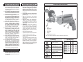
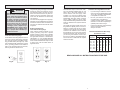
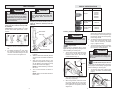
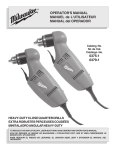
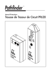
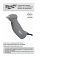
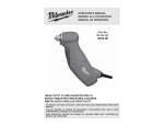
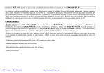
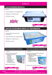
OPERATOR'S MANUAL
MANUEL de L'UTILISATEUR
MANUAL del OPERADOR
Cat. No.
No de Cat.
0100-20
0101-20
0200-20
0201-20
0202-20
0299-20
0300-20
0302-20
HEAVY-DUTY CLOSE QUARTER DRILLS
EXTRA ROBUSTES PERCEUSES COUDÉES
MINITALADRO ANGULAR HEAVY-DUTY
TO REDUCE THE RISK OF INJURY, USER MUST READ OPERATOR'S MANUAL.
AFIN DE RÉDUIRE LE RISQUE DE BLESSURES, L'UTILISATEUR DOIT LIRE LE
MANUEL DE L'UTILISATEUR.
PARA REDUCIR EL RIESGO DE LESIONES, EL USUARIO DEBE LEER EL MANUAL
DEL OPERADOR.
GENERAL SAFETY RULES — FOR ALL POWER TOOLS
WARNING
READ ALL INSTRUCTIONS
Failure to follow all instructions listed below may result in electric shock, fire and/or
serious injury. The term "power tool" in all of the warnings listed below refers to your
mains-operated (corded) power tool or battery-operated (cordless) power tool.
SAVE THESE INSTRUCTIONS
PERSONAL SAFETY
WORK AREA SAFETY
1.
2.
3.
Keep work area clean and well lit.
Cluttered or dark areas invite accidents.
Do not operate power tools in explosive atmospheres, such as in the
presence of flammable liquids, gases
or dust. Power tools create sparks which
may ignite the dust or fumes.
Keep children and bystanders away
while operating a power tool. Distractions can cause you to lose control.
9.
10.
ELECTRICAL SAFETY
4.
5.
6.
7.
8.
2
11.
Power tool plugs must match the
outlet. Never modify the plug in any
way. Do not use any adapter plugs
with earthed (grounded) power tools.
Unmodified plugs and matching outlets
will reduce risk of electric shock.
Avoid body contact with earthed or
grounded surfaces such as pipes,
radiators, ranges and refrigerators.
There is an increased risk of electric shock
if your body is earthed or grounded.
Do not expose power tools to rain or
wet conditions. Water entering a power
tool will increase the risk of electric
shock.
Do not abuse the cord. Never use the
cord for carrying, pulling or unplugging the power tool. Keep cord away
from heat, oil, sharp edges or moving
parts. Damaged or entangled cords
increase the risk of electric shock.
When operating a power tool outdoors, use an extension cord suitable
for outdoor use. Use of a cord suitable
for outdoor use reduces the risk of electric shock.
12.
13.
14.
15.
3
Stay alert, watch what you are doing and use common sense when
operating a power tool. Do not use
a power tool while you are tired or
under the influence of drugs, alcohol
or medication. A moment of inattention
while operating power tools may result
in serious personal injury.
Use safety equipment. Always wear
eye protection. Safety equipment such
as dust mask, non-skid safety shoes,
hard hat, or hearing protection used
for appropriate conditions will reduce
personal injuries.
Avoid accidental starting. Ensure the
switch is in the off-position before
plugging in. Carrying power tools with
your finger on the switch or plugging in
power tools that have the switch on invites
accidents.
Remove any adjusting key or wrench
before turning the power tool on. A
wrench or a key left attached to a rotating part of the power tool may result in
personal injury.
Do not overreach. Keep proper footing and balance at all times. This
enables better control of the power tool
in unexpected situations.
Dress properly. Do not wear loose
clothing or jewellery. Keep your hair,
clothing and gloves away from moving
parts. Loose clothes, jewellery or long hair
can be caught in moving parts.
If devices are provided for the connection of dust extraction and collection
facilities, ensure these are connected
and properly used. Use of these devices can reduce dust-related hazards.
POWER TOOL USE AND CARE
FUNCTIONAL DESCRIPTION
SPECIFIC SAFETY RULES
16. Do not force the power tool. Use the
correct power tool for your application. The correct power tool will do the
job better and safer at the rate for which
it was designed.
17. Do not use the power tool if the switch
does not turn it on and off. Any power tool
that cannot be controlled with the switch is
dangerous and must be repaired.
18. Disconnect the plug from the power
source and/or the battery pack from
the power tool before making any
adjustments, changing accessories,
or storing power tools. Such preventive safety measures reduce the risk of
starting the power tool accidentally.
19. Store idle power tools out of the
reach of children and do not allow
persons unfamiliar with the power
tool or these instructions to operate
the power tool. Power tools are dangerous in the hands of untrained users.
20. Maintain power tools. Check for
misalignment or binding of moving
parts, breakage of parts and any
other condition that may affect the
power tool's operation. If damaged,
have the power tool repaired before
use. Many accidents are caused by
poorly maintained power tools.
21. Keep cutting tools sharp and clean.
Properly maintained cutting tools with
sharp cutting edges are less likely to
bind and are easier to control.
22. Use the power tool, accessories and
tool bits etc., in accordance with
these instructions and in the manner
intended for the particular type of
power tool, taking into account the
working conditions and the work to
be performed. Use of the power tool for
operations different from those intended
could result in a hazardous situation.
1.
Hold tools by insulated gripping surfaces when performing an operation
where the cutting tool may contact
hidden wiring or its own cord. Contact
with a "live" wire will make exposed
metal parts of the tool "live" and shock
the operator.
2
3
2.
Use auxiliary handles supplied with
the tool. Loss of control can cause
personal injury.
3.
Wear ear protectors with impact
drills. Exposure to noise can cause
hearing loss.
4.
Maintain labels and nameplates.
These carry important information.
If unreadable or missing, contact a
MILWAUKEE service facility for a free
replacement.
5.
WARNING: Some dust created by
power sanding, sawing, grinding, drilling, and other construction activities
contains chemicals known to cause
cancer, birth defects or other reproductive harm. Some examples of these
chemicals are:
1.
Chuck
2.
Side handle*
3.
Nameplate
•
lead from lead-based paint
4.
Lock button
•
crystalline silica from bricks and cement
and other masonry products, and
5.
Trigger
6.
Forward/Reverse switch
arsenic and chromium from chemicallytreated lumber.
* Cat. Nos. 0200-20, 0202-20, 0299-20, 0300-20, 0302-20 only
•
Your risk from these exposures varies,
depending on how often you do this
type of work. To reduce your exposure
to these chemicals: work in a well ventilated area, and work with approved
safety equipment, such as those dust
masks that are specially designed to
filter out microscopic particles.
4
1
6
5
Symbology
Specifications
Catalog Volts
No Load
No.
AC Amps
RPM
Double Insulated
Underwriters
Laboratories, Inc.,
United States and Canada
Volts Alternating Current
SERVICE
No Load Revolutions
per Minute (RPM)
23. Have your power tool serviced by a
qualified repair person using only
identical replacement parts. This will
ensure that the safety of the power tool
is maintained.
Amperes
Mexican Approvals Marking
4
5
0100-20
0101-20
0200-20
0201-20
0202-20
0299-20
0300-20
0302-20
120
120
120
120
120
120
120
120
7
7
7
7
7
8
8
8
0 - 2500
0 - 4000
0 - 1200
0 - 2500
0 - 1200
0 - 850
0 - 850
0 - 850
GROUNDING
WARNING
EXTENSION CORDS
The grounding prong in the plug is connected
through the green wire inside the cord to
the grounding system in the tool. The green
wire in the cord must be the only wire connected to the tool's grounding system and
must never be attached to an electrically
“live” terminal.
Improperly connecting the grounding
wire can result in the risk of electric
shock. Check with a qualified electrician if you are in doubt as to whether
the outlet is properly grounded. Do
not modify the plug provided with
the tool. Never remove the grounding
prong from the plug. Do not use the
tool if the cord or plug is damaged.
If damaged, have it repaired by a
MILWAUKEE service facility before
use. If the plug will not fit the outlet,
have a proper outlet installed by a
qualified electrician.
Your tool must be plugged into an appropriate outlet, properly installed and grounded in
accordance with all codes and ordinances.
The plug and outlet should look like those
in Figure A.
Double Insulated Tools:
Tools with Two Prong Plugs
Tools marked “Double Insulated” do not
require grounding. They have a special
double insulation system which satisfies
OSHA requirements and complies with
the applicable standards of Underwriters
Laboratories, Inc., the Canadian Standard
Association and the National Electrical
Code. Double Insulated tools may be used
in either of the 120 volt outlets shown in
Figures B and C.
Grounded Tools:
Tools with Three Prong Plugs
Tools marked “Grounding Required” have a
three wire cord and three prong grounding
plug. The plug must be connected to a properly grounded outlet (See Figure A). If the
tool should electrically malfunction or break
down, grounding provides a low resistance
path to carry electricity away from the user,
reducing the risk of electric shock.
Grounded tools require a three wire extension cord. Double insulated tools can use
either a two or three wire extension cord.
As the distance from the supply outlet
increases, you must use a heavier gauge
extension cord. Using extension cords with
inadequately sized wire causes a serious
drop in voltage, resulting in loss of power
and possible tool damage. Refer to the table
shown to determine the required minimum
wire size.
Guidelines for Using Extension Cords
The smaller the gauge number of the wire,
the greater the capacity of the cord. For example, a 14 gauge cord can carry a higher
current than a 16 gauge cord. When using
more than one extension cord to make up
the total length, be sure each cord contains
at least the minimum wire size required. If
you are using one extension cord for more
than one tool, add the nameplate amperes
and use the sum to determine the required
minimum wire size.
•
If you are using an extension cord outdoors, be sure it is marked with the suffix
“W-A” (“W” in Canada) to indicate that it
is acceptable for outdoor use.
•
Be sure your extension cord is properly wired and in good electrical
condition. Always replace a damaged
extension cord or have it repaired by a
qualified person before using it.
•
Protect your extension cords from sharp
objects, excessive heat and
damp or wet areas.
Recommended Minimum Wire Gauge
for Extension Cords*
Extension Cord Length
Nameplate
Amperes
25'
50'
75' 100' 150'
0 - 2.0
2.1 - 3.4
3.5 - 5.0
5.1 - 7.0
7.1 - 12.0
12.1 - 16.0
16.1 - 20.0
18
18
18
18
16
14
12
18
18
18
16
14
12
10
18
18
16
14
12
10
18
16
14
12
10
16
14
12
12
* Based on limiting the line voltage drop to
five volts at 150% of the rated amperes.
READ AND SAVE ALL INSTRUCTIONS FOR FUTURE USE.
Fig. B
Fig. A
6
Fig. C
7
TOOL ASSEMBLY
WARNING
CHUCK IDENTIFICATION
Chuck Type
WARNING
To reduce the risk of injury,
always unplug tool before attaching
or removing accessories or making
adjustments. Use only specifically
recommended accessories. Others
may be hazardous.
Adjusting the Side Handle (Cat. No.
0200-20, 0202-20, 0299-20, 0300-20,
0302-20)
Removing and Replacing Quik-Lok ®
Cords (Cat. No. 0100-20, 0101-20, 020220, 0302-20)
Fig. 2
MILWAUKEE's exclusive Quik-Lok® Cords
provide instant field replacement or substitution.
Side handle
Fig. 1
Double sleeve
Keyless
0201-20
Single sleeve
Keyless
0202-20
0302-20
Installing and Removing Bits
Gearcase
When using screwdriver bits, insert the
bit far enough for the chuck jaws to grip
the bit shank. Tighten the chuck jaws by
hand to align the bit.
WARNING
To reduce the risk of injury, always
remove the chuck key from the chuck
after each use.
1.
2.
To remove the Quik-Lok® Cord, turn the
cord nut 1/4 turn to the left and pull it
out.
Detents
Locking keys
®
To replace the Quik-Lok Cord, align
the connector keyways and push the
connector in as far as it will go. Turn the
cord nut 1/4 turn to the right to lock.
1.
2.
3.
Side handle ring
Turn the side handle counterclockwise
to loosen.
Slide the side handle assembly forward
over the chuck and rotate to the desired
angle.
Keyed Chuck
3.
To close the chuck jaws, place the chuck
key in each of the three holes in the
chuck. Turn the chuck key clockwise
(Fig. 3). Tighten securely.
4.
To remove the bit, insert the chuck key
into one of the holes in the chuck. Turn
the chuck key counterclockwise.
These tools are equipped with a chuck
tightened using a key. Always unplug the tool
before installing or removing bits.
1.
Fig. 3
Slide the side handle back to the
gearcase and position the locking keys
into the detents. The locking keys help
prevent the handle from slipping.
WARNING
To open the chuck jaws, place the chuck
key in one (1) of the three (3) holes
located on the chuck. Turn the key
counterclockwise (Fig. 3).
To reduce the risk of injury, do not
grasp the bit while the chuck is rotating or while the bit is falling from
the chuck.
Loosen
Double Sleeve Keyless Chuck
Tighten
These tools are equipped with a hand tightening keyless chuck. Always unplug the tool
before installing or removing bits.
NOTE: The side handle ring must clear
the chuck.
4.
0100-20
0101-20
0200-20
0299-20
0300-20
Keyed
To reduce the risk of injury, always
use a side handle when using this
tool. Always brace and hold securely.
Drill Cat. No.
1.
Turn the side handle clockwise to
tighten.
NOTE: Always use the side handle for
best control.
To open the chuck jaws, hold the collar
and turn the sleeve counterclockwise
(Fig. 4).
Fig. 4
Be sure the bit shank and chuck jaws are
clean. Dirt particles may prevent the bit
from lining up properly.
2.
8
When using drill bits, insert the bit into
the chuck. Center the bit in the chuck
jaws and lift it about 1/16" off of the bottom. Tighten the chuck jaws by hand to
align the bit.
Tighten
Loosen
9
Be sure the bit shank and chuck jaws are
clean. Dirt particles may prevent the bit
from lining up properly.
2.
Be sure the bit shank and chuck jaws are
clean. Dirt particles may prevent the bit
from lining up properly.
When using drill bits, insert the bit into
the chuck. Center the bit in the chuck
jaws and lift it about 1/16" off of the bottom. Tighten the chuck jaws by hand to
align the bit (Fig. 5).
2.
Fig. 5
Fig. 8
When using screwdriver bits, insert the
bit far enough for the chuck jaws to grip
the bit shank. Tighten the chuck jaws by
hand to align the bit.
3.
When using screwdriver bits, insert the
bit far enough for the chuck jaws to grip
the bit shank. Tighten the chuck jaws by
hand to align the bit.
To close the chuck jaws, hold the
collar and turn the sleeve clockwise
(Fig. 6). Tighten securely.
Fig. 6
When using drill bits, insert the bit into
the chuck. Center the bit in the chuck
jaws and lift it about 1/16" off of the bottom. Tighten the chuck jaws by hand to
align the bit (Fig. 8).
3.
Collar
To close
To close the chuck jaws, turn the chuck
sleeve clockwise (Fig. 9). Tighten securely. Several detents will be felt as
the chuck sleeve is turned.
Fig. 9
To close
To reduce the risk of injury, wear
safety goggles or glasses with side
shields. Unplug the tool before
changing accessories or making
adjustments.
Chuck Removal
This tool is equipped with a threaded spindle
to hold the chuck. Before removing the
chuck, unplug the tool and open the chuck
jaws. A left-handed thread screw is located
inside the chuck to prevent the chuck from
loosening when the tool is operated in reverse direction. Remove the screw by turning
it clockwise. To remove the chuck, hold the
tool so that only the side of the chuck rests
firmly and squarely on a solid workbench.
Insert the chuck key or a chuck remover bar
in one of the keyholes. Turn the chuck so the
key is at about a 30° angle to the bench top
and strike the key sharply with a hammer so
the chuck turns in a counterclockwise direction (looking from the front of the tool). This
should loosen the chuck from the spindle
which has a right hand thread making it easy
to remove the chuck by hand.
Using Forward/Reverse Switch
Fig. 11
Reverse
NOTE: When replacing the chuck, always
replace the left hand thread screw in the
chuck.
1.
For forward (clockwise) rotation, push
the forward/reverse switch to the left
position as shown.
2.
For reverse (counterclockwise) rotation,
push the forward/reverse switch to the
right position as shown. Although an interlock prevents reversing the tool while
the motor is running, allow it to come to
a full stop before reversing.
To reduce the risk of injury, keep
hands and cord away from the bit
and all moving parts.
Starting, Stopping and Controlling Speed
1. To start the tool, pull the trigger.
2. To stop the tool, release the trigger.
3. To vary the drilling speed, simply increase or decrease pressure on the
trigger. The further the trigger is pulled,
the greater the speed.
The spindle will remain locked until
the tool is turned on. The spindle-lock
mechanism will automatically disengage
when the tool is turned on.
To open the chuck jaws, turn the chuck
sleeve counterclockwise (Fig. 7).
4.
Fig. 7
Trigger
WARNING
NOTE: If the spindle rotates when
opening or closing the chuck jaws,
grasp the chuck and slightly rotate back
and forth to engage the spindle-lock
mechanism.
Single Sleeve Keyless Chuck
Forward
Switch
Sleeve
To remove the bit, hold the chuck collar
and turn the sleeve counterclockwise to
release the bit from the chuck jaws.
These tools are equipped with a spindle-lock
mechanism and a single-sleeve keyless
chuck. Always unplug the tool before inserting or removing bits.
1.
WARNING
To reduce the risk of injury, always
wear eye protection.
Fig. 10
Sleeve
4.
OPERATION
WARNING
To remove the bit, turn the chuck sleeve
counterclockwise to release the bit from
the chuck jaws.
Locking Trigger
The lock button holds the trigger in the ON
position for continuous full speed use.
1. To lock the trigger, hold the lock button
in while pulling the trigger. Release the
trigger.
2. To unlock the trigger, pull the trigger and
release. The lock button will pop out.
Tighten
Loosen
10
11
Driving Screws
APPLICATIONS
Wood/Steel Steel
Wood
Cat.
No.
No Load Flat Boring Auger Hole
Bits
Bits Saws
RPM
Self-feed PathfinderTM
Bits
Bits
NR
0100-20 0 - 2500
1-1/2"
NR
NR
0101-20 0 - 4000
1-1/4"
NR
NR
0200-20 0 - 1200
1-1/2"
1"
3-1/4"
0201-20 0 - 2500
1-1/2"
7/8"
2-1/4"
NR
0202-20 0 - 1200
1-1/2"
1"
3-1/4"
0299-20 0 - 850
1-1/2"
1-1/2" 3-5/8"
0300-20 0 - 850
1-1/2"
1-1/2" 3-5/8"
0302-20 0 - 850
1-1/2"
1-1/2" 3-5/8"
Twist
Bits
Hole
Saws
NR
NR
NR
1/4"
NR
NR
1/4"
NR
NR
1-1/4"
1/2"
1-5/8"
1-1/4"
1/2"
NR
2-9/16"
1-1/4"
1/2"
1-5/8"
2-9/16"
1-1/4"
3/4"
2"
2-9/16"
1-1/4"
3/4"
2"
1-1/4"
3/4"
2"
NR = Not recommended
WARNING
When drilling in wood, composition materials
and plastic, start the drill slowly, gradually
increasing speed as you drill. When using
twist drill bits, pull the bit out of the hole
frequently to clear chips from the bit flutes.
Use low speeds for plastics with a low melting point.
Selecting Bits
When selecting a bit, use the right type for
your job. For best performance, always use
sharp bits.
Drilling in Masonry
When drilling in masonry, use high speed
carbide-tipped bits. Drilling soft masonry
materials such as cinder block requires
little pressure. Hard materials like concrete
require more pressure. A smooth, even flow
of dust indicates the proper drilling rate. Do
not let the bit spin in the hole without cutting.
Do not use water to settle dust or to cool bit.
Both actions will damage the carbide.
Drilling
1.
Before drilling, be sure the workpiece is
clamped securely. Use backing material
to prevent damage to the workpiece
during breakthrough.
2.
When starting a hole, place the drill
bit on the work surface and apply firm
pressure. Begin drilling at a slow speed,
gradually increasing the speed as you
drill.
3.
Always apply pressure in line with the bit.
Use enough pressure to keep the drill
biting, but do not push hard enough to
stall the motor.
4.
Reduce pressure and ease the bit
through the last part of the hole. While
the tool is still running, pull the bit out of
the hole to prevent jamming.
Drilling in Metal
When drilling in metal, use high speed steel
twist drills or hole saws. Use slow speeds
for hard metals and high speeds for softer
metals. Lubricate drill bits with cutting oil
when drilling in iron or steel. Use a coolant
when drilling in nonferrous metals such as
copper, brass or aluminum. Back the material to prevent binding and distortion on
breakthrough.
12
Fig. 12
Forward rotation
Stalling
Reaction
If the tool seems as if it is about to stall, maintain a firm grip and reduce pressure slightly
to allow the bit to regain speed. If the tool
does stall, release the trigger immediately.
Reverse the motor, remove the bit from the
work and start again. Do not pull the trigger
on and off in an attempt to start a stalled drill.
This can damage the drill.
Bracing against the floor
Fig. 13
Forward
rotation
Drilling in Wood, Composition Materials
and Plastic
To reduce the risk of explosion,
electric shock and property
damage, always check the work
area for hidden pipes and wires
before drilling.
Typical Bracing Methods
When driving screws, use the proper screwdriver bit for your job. After drilling pilot and
shank holes, start the screw slowly and
increase the speed as driving progresses.
Set the screw by slowing to a stop. Do not
run screws down at excessive speeds. To
remove screws, reverse the motor.
WARNING
Reaction
High rotational force. To reduce the
risk of injury, always hold or brace
securely. Always use side handle on
tools rated 1200 rpm or less.
Bracing against your leg
Fig. 14
Reaction
Bit Binding
A high rotational force occurs when a bit
binds. If the bit binds, the tool will be forced in
the opposite direction of the bit rotation (See
Fig. 12-14). Bits may bind if they are misaligned or when they are breaking through a
hole. Wood boring bits can also bind if they
run into nails or knots. Be prepared for bit
binding situations.
Reverse rotation
To reduce the chance of bit binding:
•
Use sharp bits. Sharp bits are less likely
to bind when drilling.
•
Use the proper bit for the job. There
are bits that are designed for specific
purposes.
•
Use caution when drilling pitchy, knotty,
wet or warped material or when drilling
in material that may contain nails.
Forward rotation
Bracing against a stud
13
MAINTENANCE
FIVE YEAR TOOL LIMITED WARRANTY
WARNING
WARNING
To reduce the risk of injury, always
unplug your tool before performing
any maintenance. Never disassemble
the tool or try to do any rewiring on
the tool's electrical system. Contact a
MILWAUKEE service facility for ALL
repairs.
To reduce the risk of injury, electric
shock and damage to the tool, never
immerse your tool in liquid or allow a
liquid to flow inside the tool.
Cleaning
Clean dust and debris from vents. Keep
the tool handles clean, dry and free of oil
or grease. Use only mild soap and a damp
cloth to clean your tool since certain cleaning
agents and solvents are harmful to plastics
and other insulated parts. Some of these
include: gasoline, turpentine, lacquer thinner,
paint thinner, chlorinated cleaning solvents,
ammonia and household detergents containing ammonia. Never use flammable or
combustible solvents around tools.
Maintaining Tools
Keep your tool in good repair by adopting a
regular maintenance program. Before use,
examine the general condition of your tool.
Inspect guards, switches, tool cord set and
extension cord for damage. Check for loose
screws, misalignment, binding of moving
parts, improper mounting, broken parts and
any other condition that may affect its safe
operation. If abnormal noise or vibration occurs, turn the tool off immediately and have
the problem corrected before further use.
Do not use a damaged tool. Tag damaged
tools “DO NOT USE” until repaired (see
“Repairs”).
Repairs
If your tool is damaged, return the entire tool
to the nearest service center.
Under normal conditions, relubrication is not
necessary until the motor brushes need to
be replaced. After six months to one year,
depending on use, return your tool to the
nearest MILWAUKEE service facility for the
following:
•
Lubrication
•
Brush inspection and replacement
•
Mechanical inspection and cleaning
(gears, spindles, bearings, housing,
etc.)
•
Electrical inspection (switch, cord,
armature, etc.)
•
Testing to assure proper mechanical and
electrical operation
Every MILWAUKEE electric power tool (including battery charger) is warranted to the original
purchaser only to be free from defects in material and workmanship. Subject to certain exceptions, MILWAUKEE will repair or replace any part on a electric power tool which, after examination, is determined by MILWAUKEE to be defective in material or workmanship for a period of
five (5) years* after the date of purchase. Return the electric power tool and a copy of proof
of purchase to a MILWAUKEE factory Service/Sales Support Branch location or MILWAUKEE
Authorized Service Station, freight prepaid and insured, are requested for this warranty to be
effective. This warranty does not apply to damage that MILWAUKEE determines to be from
repairs made or attempted by anyone other than MILWAUKEE authorized personnel, misuse,
alterations, abuse, normal wear and tear, lack of maintenance, or accidents.
* The warranty period for Hoists (lever, hand chain, & electric chain hoists), all Ni-CD battery
packs, Work Lights (cordless flashlights), Job Site Radios, and Trade Titan™ Industrial Work
Carts is one (1) year from the date of purchase. *The warranty period for Li-Ion battery packs
that do not contain V™-technology – 4.0 volts through 18.0 volts - is two (2) years from the
date of purchase.
*There is a separate warranty for V™-technology Li-Ion Battery Packs V™18 volts and above
that accompany V™-technology cordless power tools:
*Every MILWAUKEE V™-technology Li-Ion Battery Pack 18 volts or above is covered by an
initial 1000 Charges/2 Years free replacement warranty. This means that for the earlier of
the first 1000 charges or two (2) years from the date of purchase/first charge, a replacement
battery will be provided to the customer for any defective battery free of charge. Thereafter,
customers will also receive an additional warranty on a pro rata basis up to the earlier of the
first 2000 charges or five (5) Years from the date of purchase/first charge. This means that
every customer gets an additional 1000 charges or three (3) years of pro rata warranty on
the V™-technology Li-Ion Battery Pack 18 volts or above depending upon the amount of use.
During this additional warranty period, the customer pays for only the useable service received
over and above the first 1000 Charges/2 years, based on the date of first charge and number
of charges found on the battery pack via Milwaukee’s V™-technology Service Reader.
Warranty Registration is not necessary to obtain the applicable warranty on a MILWAUKEE
product. However, proof of purchase in the form of a sales receipt or other information deemed
sufficient by MILWAUKEE, is requested.
ACCESSORIES
WARNING
To reduce the risk of injury, always
unplug the tool before attaching or
removing accessories. Use only specifically recommended accessories.
Others may be hazardous.
ACCEPTANCE OF THE EXCLUSIVE REPAIR AND REPLACEMENT REMEDIES DESCRIBED HEREIN IS A CONDITION OF THE CONTRACT FOR THE PURCHASE OF
EVERY MILWAUKEE PRODUCT. IF YOU DO NOT AGREE TO THIS CONDITION, YOU
SHOULD NOT PURCHASE THE PRODUCT. IN NO EVENT SHALL MILWAUKEE BE LIABLE FOR ANY INCIDENTAL, SPECIAL, CONSEQUENTIAL OR PUNITIVE DAMAGES,
OR FOR ANY COSTS, ATTORNEY FEES, EXPENSES, LOSSES OR DELAYS ALLEGED
TO BE AS A CONSEQUENCE OF ANY DAMAGE TO, FAILURE OF, OR DEFECT IN ANY
PRODUCT INCLUDING, BUT NOT LIMITED TO, ANY CLAIMS FOR LOSS OF PROFITS.
THIS WARRANTY IS EXCLUSIVE AND IN LIEU OF ALL OTHER WARRANTIES OR CONDITIONS, WRITTEN OR ORAL, EXPRESSED OR IMPLIED. WITHOUT LIMITING THE
GENERALITY OF THE FOREGOING, MILWAUKEE DISCLAIMS ANY IMPLIED WARRANTY
OF MERCHANTABILITY OR FITNESS FOR A PARTICULAR USE OR PURPOSE, AND ALL
OTHER WARRANTIES.
This warranty applies to product sold in the U.S.A., Canada and Mexico only.
For a complete listing of accessories refer to
your MILWAUKEE Electric Tool catalog or go
on-line to www.milwaukeetool.com. To obtain
a catalog, contact your local distributor or a
service center.
Quik-Lok™ Cord Sets
8' - Cat. No. 48-76-4008
25' - Cat. No. 48-76-4025
14
15