1
Control Panels
D9412GV4/D7412GV4/D7212GV4
en
Owner's Manual Supplement
D9412GV4/D7412GV4/D7212GV4 | Owner's Manual Supplement
System Requirements
Minimum system requirements for Classification in
accordance with ANSI/SIA CP-01-2007:
•
UL Listed and Classified control unit Model D9412GV4,
D7412GV4, or D7212GV4
•
UL Listed and Classified keypad Model D1256, D1257,
D1260, D1255, D1255R, or D1255 RW
•
UL Listed Local Bell
The minimum firmware requirements for SIA CP-01 compliance
are:
2
Control Panel
Firmware Version
D9412GV4
1.00 or later
D7412GV4
1.00 or later
D7212GV4
1.00 or later
Bosch Security Systems, Inc. | 9/11 | F01U245224-02
D9412GV4/D7412GV4/D7212GV4 | Owner's Manual Supplement
1.0
Introduction
4
2.0
General Commands
4
2.1
Two-Man Rule
4
2.2
Early Ambush
5
2.3
Easy Exit Control
5
2.4
Passcode Follows Scope
6
2.5
Passcode Controlled Menu
7
2.6
Walk Tests
8
2.7
Door Activated Custom Function
11
2.8
Passcode Functions
11
2.9
Access Level Control
13
2.10
Door Control
14
2.11
Delete User [COMMAND 53]
18
2.12
Add/Change User - [COMMAND 56]
19
3.0
SIA CP-01 Compliance Information
27
3.1
System Requirements
27
3.2
False Alarm Reduction Features
27
3.3
User-Caused False Alarms, Arming the System
28
3.4
User-Caused False Alarms, Disarming the System
29
3.5
Arming and Disarming with Keyswitches
30
3.6
Alarm Transmission Sequence – Alarm Abort
30
3.7
Cancel Report and Cancel Window
31
3.8
Duress Alarm
31
3.9
Swinger Shutdown
31
Bosch Security Systems, Inc. | 9/11 | F01U245224-02
3
D9412GV4/D7412GV4/D7212GV4 | Owner's Manual Supplement
1.0 Introduction
This document supplements the Security System Owner’s Manual
(P/N: 71-06633-000) with the features for the GV4 Series. The
instructions for the commands listed in this document replace
those commands in the Security System Owner’s Manual. Refer to
the Owner’s Manual for the operation of your new security system
and its other basic features.
Place this supplement inside the Security System
Owner’s Manual.
2.0 General Commands
2.1
Two-Man Rule
2.1.1
Description
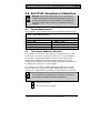
The Two-Man Rule adds an extra step to the disarming process by
requiring two unique passcodes to disarm an area from the same
keypad.
I have this feature.
I do not have this feature.
2.1.2 Using the Two-Man Rule
1. Ensure that the keypad shows idle armed text or DISARM NOW.
2. Enter a valid passcode with the authority to Passcode Disarm
by pressing the passcode digits followed by the [ENTER] or
[ENT] key.
3. The keypad shows a request for the SECOND CODE:
4. Enter a second valid passcode with the authority to Passcode
Disarm by pressing the passcode digits followed by the
[ENTER] or [ENT] key. The second passcode must be different
from the first passcode.
The area is disarmed and ready for entry.
4
Bosch Security Systems, Inc. | 9/11 | F01U245224-02
D9412GV4/D7412GV4/D7212GV4 | Owner's Manual Supplement
2.2
Early Ambush
2.2.1
Description
Early Ambush adds an extra step to the disarming process by
requiring the entry of an additional passcode to confirm that the
area is secure. The second passcode can be same as the first or
different, depending upon the configuration. The first entry
disarms the area and the second entry stops an automatic timer
from sending a duress event.
I have this feature.
I do not have this feature.
2.2.2 Using Early Ambush
1. Ensure that the keypad shows idle armed text or Disarm Now.
2. Enter a valid passcode with the authority to Passcode Disarm
by pressing the passcode digits followed by the [ENTER] or
[ENT] key.
3. Ensure that the keypad shows idle disarmed text.
4. You can now search the area; however, you must enter the
second passcode before the preset Early Ambush Time
expires.
5. Enter a second valid passcode with the authority to Passcode
Disarm by pressing the passcode digits followed by the
[ENTER] or [ENT] key.
6. The keypad shows CODE 2 VALIDATED to confirm that the
second passcode is accepted and the Early Ambush Window is
canceled. The area is disarmed and ready for entry.
2.3
Easy Exit Control
2.3.1
Description
The GV4 Series Control Panels change from one armed state to
another armed state without disarming. The Easy Exit Control
feature decreases the number of keystrokes and simplifies system
operation. This feature is available by default and is always on.
Bosch Security Systems, Inc. | 9/11 | F01U245224-02
5
D9412GV4/D7412GV4/D7212GV4 | Owner's Manual Supplement
2.3.2
Using Easy Exit Control
Switching armed states from Master to Perimeter:
1. Ensure that the keypad shows idle master armed text.
2. Press the [COMMAND] key. The keypad shows SYSTEM
COMMAND.
3. Press [3] to Perimeter Arm.
4. The keypad display shows the Exit Delay countdown.
5. Enter or exit from the premises.
Switching armed states from Perimeter to Master:
1. Ensure that the keypad shows idle perimeter armed text.
2. Press the [COMMAND] key. The keypad shows SYSTEM
COMMAND.
3. Press [1] to Master Arm.
4. The keypad shows the Exit Delay countdown.
5. Enter or exit from the premises.
2.4
Passcode Follows Scope
2.4.1
Description
The Passcode Follows Scope feature is an optional arming and
disarming restriction that can be enabled on keypads with access
to multiple areas. When this feature is set to NO, the keypad
restricts Passcode Arming and Passcode Disarming to the home
area of the keypad. When set to YES, this feature allows users to
arm or disarm all the areas to which they and the keypad have
access. This feature causes no restrictions to the keypad scope as
it pertains to any command or arming method other than
Passcode Arming or Passcode Disarming.
I have this feature.
I do not have this feature.
6
Bosch Security Systems, Inc. | 9/11 | F01U245224-02
D9412GV4/D7412GV4/D7212GV4 | Owner's Manual Supplement
2.4.2
Using Passcode Follows Scope
Arming from a keypad with Panel Wide scope and Passcode
Follows Scope enabled:
1. Ensure that the keypad shows idle disarmed text.
2. Ensure that you have a valid passcode with the authority to
Passcode Arm in all areas.
3. Enter your passcode by pressing the passcode digits followed
by the [ENTER] or [ENT] key.
4. The keypad shows ARMING: 12345678 to indicate which areas
are ready to enter, exit, delay and arm.
5. The keypad shows the exit delay countdown.
6. Exit from the premises.
Arming from a keypad with Panel Wide scope and Passcode
Follows Scope disabled (default):
1. Ensure that the keypad shows idle disarmed text.
2. Ensure that you have a valid passcode with the authority to
Passcode Arm in all areas.
3. Enter your passcode by pressing the passcode digits followed
by the [ENTER] or [ENT] key.
4. The keypad shows the exit delay countdown.
5. Exit from the premises.
2.5
Passcode Controlled Menu
2.5.1
Description
When enabled, the system prompts users to enter a passcode
before viewing the keypad menu. The system shows the user the
menu options allowed according to their authority level, thereby
providing users only pertinent commands and functions.
I have this feature.
I do not have this feature.
Bosch Security Systems, Inc. | 9/11 | F01U245224-02
7
D9412GV4/D7412GV4/D7212GV4 | Owner's Manual Supplement
2.5.2
Using Passcode Controlled Menus
On a D1255 Keypad
1. Press the [ESC] key. The keypad shows ENTER PASSCODE.
2. Enter your passcode by pressing the passcode digits followed
by the [ENT] key. The first menu item for which you have
authority appears.
On a D1260 Keypad:
1. Press the Menu softkey in the lower right corner. The keypad
shows ENTER PASSCODE then press [ENTER].
2. Enter your passcode by pressing the passcode digits followed
by the [ENTER] key.
The first and second menu items for which you have authority
appear.
2.6
Walk Tests
2.6.1
Description
The D9412GV4, D7412GV4, and D7212GV4 have three Walk Test
menus that allow the user to test various points that are within
the scope of the keypad without sending a report to the central
station.
When performing a Walk Test, the Walk Test menu indicates that
the menu is ready to time out, and clearly indicates on all keypads
in the area of operation that a test is in progress. Additionally, the
Walk Test procedure issues point trouble conditions for any 24-hr
or fire points that remain off-normal when the Walk Test menu
exits. After the system annunciates the trouble condition, faulted
points are automatically swinger shunt bypassed regardless of the
point index settings. These features are always enabled and have
no configuration parameters. The warning tones commence 5 min
prior to timeout.
Test each smoke detector according to the manufacturer’s
instructions.
8
Bosch Security Systems, Inc. | 9/11 | F01U245224-02
D9412GV4/D7412GV4/D7212GV4 | Owner's Manual Supplement
Table 1:
Test Type
Walk Test Menu Access
Menu Function Name
Walk
Command
Sequence
[COMMAND][4][4]
WALK TEST ?
Fire
[COMMAND][5][8]
FIRE TEST ?
Invisible
Not applicable
INVISIBLE TEST ?
Point Types
Tested
Visible
Perimeter and
Interior
Fire and 24hour
Invisible
Perimeter and
Interior
I have this feature.
I do not have this feature.
2.6.2
Using Walk Test
On a D1255 Keypad
1. If you use the command sequence, press the keys shown in
the Command Sequence column of Table 1 for the necessary
test. The keypad shows the number of testable points within
the scope of the keypad: ### PTS TO TEST. Proceed to Step
5.
2. If you use menu function list, press the [ESC] key.
3. Press the [NEXT] key until the Menu Function Name (refer to
Table 1) appears.
4. Press the [ENT] key to activate the selected walk test function.
The keypad shows the number of testable points within the
scope of the keypad: ### PTS TO TEST
5. Press the [NEXT] key to see VIEW UNTESTED?
6. Press the [ENT] key to view the untested points. The keypad
shows the total number of untested points within the keypad
scope: ### PTS UNTESTED.
7. Press the [NEXT] key to view the first point’s name.
8. Press the [ENT] key to view the point’s hardware state. Refer
to Table 2.
Bosch Security Systems, Inc. | 9/11 | F01U245224-02
9
D9412GV4/D7412GV4/D7212GV4 | Owner's Manual Supplement
Table 2:
Display
1PT###
1PT###
1PT###
1PT###
Hardware States of Points
Text
NORMAL HW
OPEN HW
SHORT HW
MISSNG HW
Hardware State
Normal
Opened
Shorted
Missing
9. Activate the point’s sensor and observe the appropriate state
change.
10. Press the [NEXT] key to advance to the next untested point
within the scope of the keypad.
11. Repeat Steps 8 through 10 until all points are tested.
On a D1260 Keypad
1. If you use the command sequence, press the keys indicated in
the Command Sequence column of Table 1 on page 9 for the
necessary walk test. The keypad shows the number of testable
points within the scope of the keypad: ### points remain to
be tested. Proceed to Step 5.
2. If you use the menu function list, press the Menu softkey in the
lower right corner.
3. Press the Next softkey until the Menu Function Name (refer to
Table 1 on page 9) appears.
4. Press the corresponding softkey to activate the necessary
Walk Test functions.
The keypad shows the number of testable points within the
scope of the keypad: ### points remain to be tested.
5. Press the View untested Pts softkey to see ### PTS
UNTESTED.
6. Press the Next Pt softkey to view the first or next untested
point:
[Point Text]
Area #, Pt #
[Point State] HW
<Exit
10
Next PT>
Prev PT>
Bosch Security Systems, Inc. | 9/11 | F01U245224-02
D9412GV4/D7412GV4/D7212GV4 | Owner's Manual Supplement
The point state can be NORMAL, OPEN, SHORT, or
MISSING.
7. Activate the point’s sensor and observe the state change.
8. Repeat Steps 5 through 7 until all points are tested.
2.7
Door Activated Custom Function
2.7.1
Description
The D9412GV4 and D7412GV4 allow a custom function to be
activated when user credentials are presented to a D9210C Door
Controller Reader. The custom function executes as if the user
performed a function at the keypad that is associated with the
door controller.
I have this feature.
I do not have this feature.
2.7.2
Using Door Activated Custom Functions:
Executing the door’s custom function by a user that has authority
to do so when disarming the area:
1. Ensure that the area you are about to enter is armed.
2. Present your user credentials to the D9210C Door Controller
Reader. The area disarms and the custom function executes.
The area is now safe to enter.
2.8
Passcode Functions
The GV4 series control panels have several programmable function
options that can be associated with a passcode entry at a
specified keypad. Primary authentication requires a passcode
only. Optionally, a keypad can be programmed for Dual
Authentication where two forms of credentials are required. When
enabled, the secondary authentication is performed with a Door
Controller Reader using a token or a card provided by your dealer.
Once a user’s credentials are authenticated, the configured
function will be performed. Even though an access control device
is used for authentication, the configured Passcode Function may
not be an access operation.
Bosch Security Systems, Inc. | 9/11 | F01U245224-02
11
D9412GV4/D7412GV4/D7212GV4 | Owner's Manual Supplement
I have One of the following Passcode Functions configured:
Arm / Disarm (default) - All areas within the scope of the
user and keypad have their arm state changed. If the
current area is armed, it will disarm. If the current area is
disarmed, it will arm.
Cycle Door / Grant Access - The door associated with
the keypad will momentarily unlock. If enabled, the
current area will disarm or switch to perimeter armed,
then (if enabled) a custom function will execute (refer to
section 2.7 for details).
Cycle Relay - A pre-configured function will momentarily
activate.
Auto Re-Arm - All armed areas within the scope of the
user and keypad will restart their exit delay. If the current
area is disarmed, no action is taken.
2.8.1
Dual Authentication
The GV4 Series control panels provide a dual authentication feature
using a keypad and a door reader. When a keypad and door
controller reader are paired together, they require two forms of
identification from the same user before a pre-configured
passcode function is performed. The authenticating user must
have a passcode and a door credential assigned for the Dual
Authentication process to allow the configured operation to be
performed.
I have this feature.
I do not have this feature.
The Dual Authentication feature is only available on the
D9412GV4 and D7412GV4
2.8.2 Dual Authentication Process
The Dual Authentication process can be performed by entering a
passcode followed by the [ENT] or [ENTER] key, then presenting
valid access credentials to the associated Door Controller reader.
12
Bosch Security Systems, Inc. | 9/11 | F01U245224-02
D9412GV4/D7412GV4/D7212GV4 | Owner's Manual Supplement
The Dual Authentication process is also valid if the access
credential is presented first. Access credentials are usually a token
or a card and are provided by your dealer.
The control panel requires the passcode and the credential of the
same user to be presented within a configurable amount of time.
The allowed duration of time can be between 10 to 45 seconds.
Consult your dealer if the travel time between the keypad and the
Door Controller reader is longer than the configured time. The
default time is 10 seconds.
2.9
Access Level Control
2.9.1
Description
Use this function to manually enable or disable access authority
levels assigned to users. This function can be used to disable a
user’s access level temporarily instead of deleting and adding the
user.
I have this feature.
I do not have this feature.
2.9.2
Using ACCESS LEVEL CTL?
On a D1255 Keypad
1. Activate the door’s custom functions. Refer to Section 2.7.2
Using Door Activated Custom Functions.
2. Ensure that the display shows idle disarmed text.
3. Press the [MENU] key to enter the function list, then press
[NEXT] repeatedly until you reach the CHANGE LEVEL CTL?
prompt. Press [ENT].
4. ACCESS LEVEL CTL appears, indicating that you are affecting
the authority levels of cards or tokens and not passcodes.
Press [ENT].
5. ENTER LEVEL appears. Enter the access authority level
number and press [ENT].
6. If the access level is currently disabled, LEVEL # ENABLE?
appears. If the access level is currently enabled, LEVEL #
DISABLE? appears. Press [ENT] to accept the choice.
7. ENTER LEVEL appears again. Press [ESC].
Bosch Security Systems, Inc. | 9/11 | F01U245224-02
13
D9412GV4/D7412GV4/D7212GV4 | Owner's Manual Supplement
On a D1260 Keypad
1. Activate the door’s custom functions. Refer to Section 2.7.2
Using Door Activated Custom Functions.
2. Ensure that the display shows idle disarmed text.
3. Press the Menu softkey to enter the function list. Then press
the Next softkey repeatedly until you reach the Change
Level? prompt.
4. Press the Change Level ? softkey. Access Control Level
appears, indicating that you are affecting the authority levels
of cards or tokens and not passcodes.
5. Enter Level #: appears. Enter the access authority level
number and press [ENTER].
6. If the access level is currently disabled, Enable Level?
appears. If the access level is currently enabled, Disable
Level? appears. Press [ENTER] to accept the choice.
7. Repeat Steps 5 and 6 as necessary.
2.10 Door Control
2.10.1 Description
The door control function has three sub-functions:
• CYCLE DOOR?
• UNLOCK DOOR?
• SECURE DOOR?
CYCLE DOOR? unlocks a door briefly to allow a person into an
area.
UNLOCK DOOR? unlocks a door to allow free access.
SECURE DOOR? locks a door and prohibits access regardless of a
user’s authority level.
I have this feature.
I do not have this feature.
2.10.2 Using Door Control?
On a D1255 Keypad
1. Ensure that the display shows idle disarmed text.
2. Press the [COMMAND] key. The display shows SYSTEM
COMMAND.
3. Press [4] and [6].
14
Bosch Security Systems, Inc. | 9/11 | F01U245224-02
D9412GV4/D7412GV4/D7212GV4 | Owner's Manual Supplement
You can use the function list in place of steps 2 and 3 to
start this function.
1. Press the [MENU] key to enter the function list.
2. Press [NEXT] repeatedly until you reach the DOOR
CTRL? prompt.
3. Press [ENT].
4. The first sub-function that appears is CYCLE DOOR?. You can
cycle through the three sub-functions by pressing [PREV] and
[NEXT].
On a D1260 Keypad
1. Ensure that the display shows idle disarmed text.
2. Press the [COMMAND] key. The display shows *System
Command*.
3. Press [4] and [6].
You can use the function list in place of steps 2 and 3 to
start this function.
1. Press the Menu softkey to enter the function list.
2. Press the Next softkey repeatedly until you reach the
Door Control? softkey.
3. Press the Door Control ? softkey.
4. All authorized door control function sub-functions are listed.
Press the corresponding softkey to enter the sub-function.
2.10.3 Cycle Door?
1. To unlock an access door briefly and allow a person into an
area, press [ENT] at the Cycle Door? prompt.
The display shows CYCLE 1 2 3 4 5 6 7 8 if all doors are in
a normal state and available. If a door is not in a normal state,
the number of the door is replaced with one of the symbols
indicated in Table 3.
Depending on your keypad, the operations in this
section are the same, but the keypad display and keys
are slightly different.
Bosch Security Systems, Inc. | 9/11 | F01U245224-02
15
D9412GV4/D7412GV4/D7212GV4 | Owner's Manual Supplement
Table 3: Key to Symbols
Symbol
--C
U
X
P
Description
Door is not active, not in scope, or user does not
have access level authority
Door is timed door sequence
Strike and shunt are latched active (held open)
Strike and shunt are deactivated (secured)
There is a problem with the door; call your security
company
2. Enter the number of the door to cycle then press [ENT]. This
door cycles and the display changes to reflect the new status
of the doors. For example, to cycle Door 3, at the
CYCLE DOOR 1 2 3 4 5 6 7 8 prompt, press [3], then press
[ENT]. The display shows CYCLE DOOR 1 2 C 4 5 6 7 8.
This indicates that all doors are in a normal state, except for
Door 3, which is cycled.
3. Press [ESC] to leave this sub-function, or enter another door
number to cycle.
2.10.4 Unlock Door?
Depending on your keypad, the operations in this
section are the same, but the keypad display and keys
are slightly different.
1. To unlock a door to allow free access, at the CYCLE DOOR?
prompt, press [NEXT] to enter the UNLOCK DOOR?
sub-function.
2. The display shows UNLOCK 1 2 3 4 5 6 7 8 if all doors are
in a normal state and available. If a door is not in a normal
state, the number of the door is replaced with a symbol
indicated in Table 3 on page 16.
3. Enter the number of the door to unlock then press [ENT]. This
door unlocks and the display changes to reflect the new status
of the doors.
For example, to unlock Door 4, at the following prompt,
press [4], then press [ENT].
UNLOCK DOOR 1 2 3 4 5 6 7 8
16
Bosch Security Systems, Inc. | 9/11 | F01U245224-02
D9412GV4/D7412GV4/D7212GV4 | Owner's Manual Supplement
The display shows UNLOCK DOOR 1 2 3 U 5 6 7 8
This indicates that all doors are in a normal state, except for
Door 4, which is unlocked.
4.
Press [ESC] to leave this sub-function, or enter another door
number to unlock.
2.10.5 Secure Door?
Depending on your keypad, the operations in this
section are the same, but the keypad display and keys
are slightly different.
1. To secure a door to prohibit access to users regardless of their
access authority level, at the CYCLE DOOR? prompt, press
[PREV] to enter the SECURE DOOR? sub-function.
2. The display shows SECURE 1 2 3 4 5 6 7 8 if all doors are
in a normal state and available. If a door is not in a normal
state, the number of the door is replaced with a symbol
indicated in Table 3 on page 16.
3. Enter the number of the door to secure then press [ENT]. This
door secures, and the display changes to reflect the new
status of the doors.
For example, to secure Door 5, press [5], then press [ENT] at
the following prompt: SECURE DOOR 1 2 3 4 5 6 7 8
The display shows SECURE DOOR 1 2 3 4 X 6 7 8. This
indicates that all doors are in a normal state, except for
Door 5, which is secured.
4. Press [ESC] to leave this sub-function, or enter another door
number to unlock.
Bosch Security Systems, Inc. | 9/11 | F01U245224-02
17
D9412GV4/D7412GV4/D7212GV4 | Owner's Manual Supplement
Each of these sub-functions acts as a toggle switch. To
return a door to its normal state, follow the same
procedure used to change its state. For example, if
Door 3 is secured, to return it to its normal state, at
the SECURE DOOR? prompt, enter [3] and press [ENT].
The door is no longer secured and the X is replaced
with the number 3.
2.11 Delete User [COMMAND 53]
2.11.1 Description
Use this function to delete a personal passcode from your system
without assistance from your security company. You must know
the user number for the passcode you want to delete.
I have this feature.
I do not have this feature.
2.11.2 Using DEL USER ?
1. Ensure that the display shows idle disarmed text.
2. Press the [COMMAND] key. The display shows SYSTEM
COMMAND.
3. Press [5] and [3].
You can use the function list in place of steps 2 and 3
to start this function.
1. Press the [MENU] key to enter the function list.
2. Press [NEXT] repeatedly until you reach the DEL
USER? prompt.
3. Press [ENT].
4. The display shows DEL USER #. Enter the user number and
press [ENT].
5. USER ## (or user text, such as the name of the user, if this
feature was programmed into your system by your security
company) appears, allowing for confirmation. Press [ENT].
If this is not the user you wish to delete, press the [NEXT] or
[PREV] key until the correct user name appears, then press
[ENT].
18
Bosch Security Systems, Inc. | 9/11 | F01U245224-02
D9412GV4/D7412GV4/D7212GV4 | Owner's Manual Supplement
6. The display shows DELETE USER ##?. Press [ENT] to delete
user, and USER DELETED appears. If the user number is not in
the system, NOT IN USE appears. If you made an error and do
not wish to delete this user, press [ESC].
2.12 Add/Change User - [COMMAND 56]
2.12.1 Description
Use this function to add or change a passcode or card without
assistance from your security company. Before adding or changing
a passcode or card, you must know which user numbers are
available, the authority level you want to assign to the new user,
and the areas in which the passcode or card are valid.
I have this feature.
I do not have this feature.
2.12.2 Using Add User ?
On a D1255 Keypad
1. Ensure that the display shows idle disarmed text.
2. Press the [COMMAND] key. The display shows SYSTEM
COMMAND.
3. Press [5] and [6]. Enter passcode if necessary.
You can also use the function list in place of Steps 2
and 3 to start this function.
1. Press the [MENU] key to enter the function list.
2. Press [NEXT] until you reach the ADD/CHNG USER?
prompt.
3. Press [ENT].
4. The display shows ENTER USER #. Enter the user number and
press [ENT].
5. The display shows USER # (or user text, such as the name of
the user, if this feature was programmed into your system by
your security company) to allow for confirmation.
Press [ENT] if the correct user number (or user name)
appears. Press [ESC] if not.
6. ADD PASSCODE? appears. (If the user number already exists,
CHANGE PASSCODE? Appears.) Press [ENT].
Bosch Security Systems, Inc. | 9/11 | F01U245224-02
19
D9412GV4/D7412GV4/D7212GV4 | Owner's Manual Supplement
7. ENTER NEW CODE appears. Enter the new passcode followed
by [ENT]. ENTER AGAIN appears.
8. Enter the new passcode a second time for confirmation. Press
[ENT]. The display shows PASSCODE ADDED (or PASSCODE
CHANGED if the user number was already in the system).
For systems with access control, the following
prompts are available: ADD CARD? and CHANGE
CARD?. Refer to Systems With Access Control on page
22 for details.
The system does not accept a passcode that is within
two digits of an existing passcode. This is to avoid
conflicts with duress passcodes. For example, if
passcode 123 is already programmed in the system,
the system does not accept 121, 122, 124, or 125 as
passcodes.
9. ADD LEVEL? appears. If the user number already exists,
CHANGE LEVEL? appears. Press [ENT].
10. VALID AREA 1? appears. If you wish this user number to be
valid in Area 1, press [ENT]. If not, press [NEXT].
11. AUTH LEVEL appears. Assign the authority level you wish the
user number to have for this area and press [ENT]. Record this
information.
12. VALID AREA 2? appears. Enter the information necessary for
the areas in the scope of the keypad by following Steps 10 and
11 for each area (up to 8 areas).
13. LEVEL ADDED or LEVEL CHANGED appears when all area
assignments are made. Press [ENT].
At the end of each function, press [ESC] to return to
the ENTER USER # prompt. Press [ESC] again to return
to idle text.
On a D1260 Keypad
14. Ensure that the display shows idle disarmed text.
15. Press the [COMMAND] key. The display shows *System
Command*.
16. Press [5] and [6]. Enter passcode if necessary.
20
Bosch Security Systems, Inc. | 9/11 | F01U245224-02
D9412GV4/D7412GV4/D7212GV4 | Owner's Manual Supplement
You can also use the function list in place of steps 2 and
3 to start this function.
1. Press the Menu softkey to enter the function list.
2. Press the Next softkey until you reach the
Add/Change User? prompt.
3. Press the corresponding softkey. Proceed to step 4.
17. The display shows Add / Change User Enter user #:
Enter the user number and press [ENTER].
18. The display shows User ### followed by the configured user
name text. Press the Continue softkey if the correct user
number (and user name) appears. Press the Exit softkey and
return to step 4.
19. The Add/Change Menu appears. Press the Passcode softkey.
20. Add a passcode for this user? appears with the
configured user name text at the top. Press the Yes softkey.
21. Enter new passcode appears. Enter the new passcode
followed by [ENTER]. Enter new passcode again. appears.
22. Enter the new passcode a second time for confirmation. Press
[ENTER]. The display shows Passcode Added or Passcode
Changed.
23. Add Auth. Level for this User? appears. Press the Yes
softkey.
24. Is this user authorized in Area 1? appears. Press the
Yes softkey if authorized, No if not.
25. User's Current authority level: # appears. Enter the
new level followed by [ENTER] to accept.
26. Is this user authorized in Area 2? appears. Press the
Yes softkey if authorized, No if not.
27. User's Current authority level: # appears. Enter the
new level followed by [ENTER] to accept. Repeat Steps 26 and
27 until all authorized areas are set.
28. Level Added or Level Changed appears when all area
assignments are made. Press [ENTER].
Bosch Security Systems, Inc. | 9/11 | F01U245224-02
21
D9412GV4/D7412GV4/D7212GV4 | Owner's Manual Supplement
Systems With Access Control
If your system includes access control features, such as card
readers at doors, the following prompts can appear during the
ADD USER? procedure.
On a D1255 Keypad
ADD CARD? (CHANGE CARD?)
1. If the user has card or token access to the building or area,
press [ENT] at the ADD CARD? prompt, or at the CHANGE
CARD? prompt if the user already has a card or token.
2. PRESENT CARD appears. Present the card at the card reader
and wait for the tone.
3. If the reader identifies the card or token correctly, a tone
sounds and the keypad shows CARD ADDED, or CARD
CHANGED if the user already has a card or token. Press [ENT].
On a D1260 Keypad
1. From the Add/Change Menu, press the Card softkey.
2. Add Access Card for this user? appears. Press the Yes
softkey.
3. Present card to card reader # now. appears. Present
access credentials to the associated door reader and wait for a
tone.
4. If the reader identifies the credential correctly, a tone sounds
and the keypad shows Card Added or Card Changed if the
user already has a card or token. Press [ENTER].
2.12.3 Systems with Wireless Keyfobs
If your system has wireless services available, the following
options are available to enroll, remove or replace a User Keyfob
provided by your security company.
I have this feature.
I do not have this feature.
Enrolling a User Keyfob with RFID
On a D1255 Keypad
1. Ensure that the display shows idle disarmed text.
22
Bosch Security Systems, Inc. | 9/11 | F01U245224-02
D9412GV4/D7412GV4/D7212GV4 | Owner's Manual Supplement
2. Press the [COMMAND] key. The display shows *System
Command*.
3. Press [5] and [6]. Enter passcode if necessary.
4. At the USER KEYFOBS? prompt, press [ENT].
5. ENTER RFID appears. Press [ENT].
6. USER ###: KEYFOB appears scrolling with NOT ASSIGNED.
Press [ENT].
7. RFID: prompt appears. Enter the RFID number provided by
your security company. Press [ENT] when done.
8. PARAMETER SAVED appears, then USER ###: KEYFOB scrolling
with the RFID number.
On a D1260 Keypad
1. From the Add/Change Menu press the Keyfob softkey.
2. Configure RF Keyfob for this user? appears. Press the
Yes softkey.
3. Select the Enter Keyfob RFID softkey. Keyfob User (###)
RFID: Not Assigned appears.
4. Press the Edit softkey. The RFID: prompt appears.
5. Enter the RFID number provided by your security company.
Press the Save softkey when finished.
6. PARAMETER SAVED appears, then Keyfob User (###) RFID:
######## appears. Press the Exit softkey.
Enrolling a User Keyfob with Auto-learn
On a D1255 Keypad
1. At the USER KEYFOBS? prompt, press [ENT].
2. ENTER RFID appears. Press [NEXT] until ADD KEYFOB appears.
Press [ENT].
3. KEYFOB USER: ### appears scrolling with NOT ASSIGNED.
Press [ENT] to activate Auto-Learn mode.
4. ADDING (###) appears scrolling with RESET XMITTER. Press
the [RESET] button on the Keyfob.
5. If successful, KEYFOB ADDED appears. KEYFOB USER: ###
appears scrolling with AUTO-LEARNED. Press [ESC] to exit.
6. If not successful, an error message is displayed. KEYFOB USER:
### appears scrolling with NOT ASSIGNED. Press [ESC] to exit.
Bosch Security Systems, Inc. | 9/11 | F01U245224-02
23
D9412GV4/D7412GV4/D7212GV4 | Owner's Manual Supplement
On a D1260 Keypad
1. From the Add/Change Menu press the Keyfob softkey.
2. Configure RF Keyfob for this user? appears. Press the
Yes softkey.
3. Press the Add Keyfob softkey. Keyfob User (###) RFID:
Not Assigned appears.
4. Press the Add softkey. Adding Keyfob: (###) Press
Xmitter Reset appears. Press the [RESET] button on the
keyfob.
5. If successful, Keyfob Added appears followed by Keyfob
User (###) RFID: Auto-Learned. Press the Exit softkey.
6. If not successful, an error message is displayed followed by
Keyfob User (###) RFID: Not Assigned. Press the Exit
softkey.
24
Bosch Security Systems, Inc. | 9/11 | F01U245224-02
D9412GV4/D7412GV4/D7212GV4 | Owner's Manual Supplement
Replace a User Key Fob
On a D1255 Keypad
1. At the USER KEYFOBS? prompt, press [ENT].
2. ENTER RFID appears. Press [NEXT] until REPLACE KEYFOB
appears. Press [ENT].
3. KEYFOB USER: ### appears scrolling with AUTO-LEARNED if the
keyfob to be replaced was auto-learned, or KEYFOB USER (###)
RFID: {assigned RFID #} appears. Press [ENT].
4. REPLACING (###) appears scrolling with RESET XMITTER.
Press the [RESET] button on the Keyfob.
5. If successful, KEYFOB ADDED appears. KEYFOB USER: ###
appears scrolling with AUTO-LEARNED. Press [ESC] to exit.
6. If not successful, an error message is displayed. KEYFOB USER:
### appears scrolling with NOT ASSIGNED. Press [ESC] to exit.
On a D1260 Keypad
1. From the Add/Change Menu press the Keyfob softkey.
2. Configure RF Keyfob for this user? appears. Press the
Yes softkey.
3. Press the Replace Keyfob softkey. Keyfob User: ###
appears scrolling with Auto-Learned if the keyfob to be
replaced was auto-learned, or Keyfob User (###) RFID:
{assigned RFID #} appears.
4. Press the Replace softkey. Replacing Keyfob: (###)
Press Xmitter Reset appears. Press the [RESET] button on
the Keyfob.
5. If successful, Keyfob Added appears followed by Keyfob
User (###) RFID: Auto-Learned. Press the Exit softkey.
6. If not successful, an error message is displayed followed by
Keyfob User (###) RFID: Not Assigned. Press the Exit
softkey.
Remove a User Keyfob
On a D1255 Keypad
1. At the USER KEYFOBS? prompt, press [ENT].
2. ENTER RFID appears. Press [NEXT] until REPLACE KEYFOB
appears. Press [ENT].
Bosch Security Systems, Inc. | 9/11 | F01U245224-02
25
D9412GV4/D7412GV4/D7212GV4 | Owner's Manual Supplement
3. KEYFOB USER: ### appears scrolling with AUTO-LEARNED.
Press [ENT] to remove a keyfob.
4. If successful, KEYFOB REMOVED appears. KEYFOB USER: ###
appears scrolling with NOT ASSIGNED. Press [ESC] to exit.
5. If not successful, an error message is displayed. KEYFOB USER:
### appears scrolling with NOT ASSIGNED. Press [ESC] to exit.
On a D1255 Keypad
1. From the Add/Change Menu press the Keyfob softkey.
2. Configure RF Keyfob for this user? appears. Press the
Yes softkey.
3. Press the Next softkey. Press the Remove Keyfob softkey.
4. Keyfob User (###) RFID: {assigned RFID #} appears.
Press the Remove softkey.
5. If successful, Keyfob Removed appears followed by Keyfob
User (###) RFID: Not Assigned. Press the Exit softkey.
6. If not successful, an error message is displayed followed by
Keyfob User (###) RFID: Not Assigned. Press the Exit
softkey.
26
Bosch Security Systems, Inc. | 9/11 | F01U245224-02
D9412GV4/D7412GV4/D7212GV4 | Owner's Manual Supplement
3.0 SIA CP-01 Compliance Information
Warning: The default programming for the control panel
includes a 30-second communication delay for alarms on
non-fire zone types. It can be removed (or increased to 45
sec) at the option of the end user in consultation with the
installer.
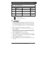
3.1
System Requirements
The minimum system requirements for SIA CP-01 compliance are:
Table 4:
System Requirements
Control Panel
D9412GV4
D7412GV4
D7212GV4
3.2
Firmware Version
1.00 or later
1.00 or later
1.00 or later
False Alarm Reduction Features
False alarms are such an issue that the local authorities in some
jurisdictions no longer respond to alarms. The Security Industry
Association (SIA) has developed a Control Panel False Alarm
Reduction Standard that details design features for security
control panels and their associated arming and disarming devices
to reduce the occurrence of false alarms.
This section of the user’s guide supplement will help to explain
proper operation of your SIA CP-01 compliant Bosch Security
Systems, Inc. D9412GV4, D7412GV4, or D7212GV4 Control Panel.
Your installation company must configure all features
necessary to provide SIA CP-01 compliance.
I have this feature.
I do not have this feature.
Bosch Security Systems, Inc. | 9/11 | F01U245224-02
27
D9412GV4/D7412GV4/D7212GV4 | Owner's Manual Supplement
3.3
User-Caused False Alarms, Arming the System
3.3.1
Exit Time Defaults
The SIA standard calls for Exit Time to range from 45 sec to at
least two min (not to exceed 255 sec).
The default is 60 sec.
3.3.2
Exit Tone
The SIA standard requires that the control panel provide an Exit
Tone to alert anyone remaining in the premises that Exit Delay is
in process. The tone pulsing rate increases during the last 10 sec
of Exit Time.
The Exit Tone can be disabled only for individual keypads, not for
the entire system.
During the last 10 sec of Exit Delay, the control panel’s Alarm Bell
output pulses on and off for the last 10 sec of Exit Delay.
3.3.3
Exit Time Restart
The SIA standard requires that the control have an option that
restarts Exit Delay if a user follows these steps:
1. Starts Exit Delay (arms the system)
2. Exits and closes an Exit Delay zone.
3. Returns through an Exit Delay zone.
4. The control panel restarts Exit Delay (one-time restart only).
I have this feature.
I do not have this feature.
3.3.4
Exit Error
When a user leaves an Exit Delay zone faulted at the end of Exit
Time, the control panel creates an “Exit Error” event as specified
by the SIA standard:
1. An Exit Delay point remains faulted at the end of Exit Delay.
2. Entry Delay starts. Keypads show DISARM NOW and the Entry
Tone sounds.
28
Bosch Security Systems, Inc. | 9/11 | F01U245224-02
D9412GV4/D7412GV4/D7212GV4 | Owner's Manual Supplement
3. The user does not return to stop Entry Delay. The Entry Delay
time expires.
4. The control panel starts the alarm transmission sequence,
accompanied by an Exit Error report.
3.3.5
Master Arm − No Exit Feature (Unvacated Premises)
If a user Master Arms an area and does not leave the premises (no
Entry/Exit zones are faulted during the exit time), the control
panel’s No Exit feature automatically shifts the Area from Master
Armed to Perimeter Armed.
I have this feature.
I do not have this feature.
3.3.6
Recent Closing
If an alarm occurs within two min of the expiration of Exit Time,
the control panel creates an “alarm-recent closing” event. If the
user armed with a passcode, the user number is included in the
recent closing report.
Recent Closing events are not created for Fire Alarm events.
3.4
User-Caused False Alarms, Disarming the
System
3.4.1
Entry Time Defaults
The SIA standard requires an Entry Time of between 30 sec and
4 min. The required default is 30 sec. If the system is not
disarmed within Entry Time, the control panel creates an Alarm
Event.
During the Entry Time, the control panel sounds an Entry Delay
Tone (distinct from the alarm tone).
3.4.2
Passcode Disarms System (Area)
When the control panel is in Entry Delay, entering a valid passcode
disarms the system as soon as the last digit of the passcode is
entered. No other keys are required.
When the control panel is in Exit Delay or is armed, entry of a valid
Passcode must be followed by an [ENTER] or [ENT] key.
Bosch Security Systems, Inc. | 9/11 | F01U245224-02
29
D9412GV4/D7412GV4/D7212GV4 | Owner's Manual Supplement
3.5
Arming and Disarming with Keyswitches
Arming Beeps and Flashes
The SIA standard requires that the control panel provide a means
to annunciate a change in arming state made from a Keyswitch.
The Alarm Bell output pulses on twice when a user disarms with a
remote device. The Alarm Bell output pulses on once when a user
arms with a remote device
3.6
Alarm Transmission Sequence – Alarm Abort
The SIA standard requires an Alarm Abort feature. The control
panel uses this feature to give end users an opportunity to
acknowledge an alarm event and abort the alarm transmission.
The following sections explain how this feature works.
3.6.1
Abort Window
The Abort Window is the time the end user has to acknowledge an
alarm and effectively “abort” the control panel’s alarm response.
The Abort Window is programmable.
• The minimum duration is 15 sec.
• The maximum duration is 45 sec.
• The default is 30 sec.
In accordance with UL standards, the SIA standard
intends that the combined Entry Time and Abort
Window will not be programmed to exceed one
minute.
3.6.2
Passcode Acknowledges Alarm
When the control panel is sounding an alarm, enter [passcode] +
[ESC] to silence the alarm without disarming. Entering the first
digit of the passcode temporarily silences the alarm at the keypad.
If a valid passcode is not entered, the alarm begins sounding again
after a period of about 10 sec with no keypad activity.
30
Bosch Security Systems, Inc. | 9/11 | F01U245224-02
D9412GV4/D7412GV4/D7212GV4 | Owner's Manual Supplement
3.6.3
Alarms Acknowledged within the Abort Window
If the end user acknowledges an alarm within the Abort Window:
• The alarm output is silenced.
• No alarm, restoral, or cancel reports are sent.
• No alarm, restoral, or cancel reports are entered in the control
panel event log.
3.6.4
At the End of the Alarm Abort Window
If no user acknowledges the alarm within the Alarm Abort Window,
the control panel sends the appropriate alarm reports.
3.7
Cancel Report and Cancel Window
If a user acknowledges an alarm after the Abort Window expires,
but before Bell Time expires, the control panel sends a Cancel
Report. The Cancel Window starts when the alarm is sent and
stops when the Alarm Bell timer expires or a user acknowledges
an alarm.
3.8
Duress Alarm
This feature allows any passcode with the Send Duress permission
enabled to always send a Duress Alarm event upon entry. The
Duress Alarm feature allows an installation to allocate unique
passcodes as the main duress passcodes for all users.
Additionally, when the SIA CP-01 compliant Duress Alarm option is
enabled, the Passcode +1 and +2 options are disabled.
3.9
Swinger Shutdown
This feature allows for a control panel to automatically bypass a point
that reports two or more alarm or trouble events within the same arm
cycle. The maximum number of faults allowed on a point is called the
Swinger Count. This value was set by the installer.
Bosch Security Systems, Inc. | 9/11 | F01U245224-02
31
Bosch Security Systems, Inc.
130 Perinton Parkway
Fairport, NY 14450
USA
www.boschsecurity.com
© Bosch Security Systems, Inc., 2011