1
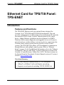
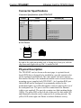
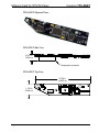
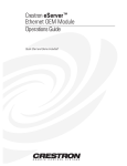
Crestron TPS-ENET Ethernet Card for TPS/Tilt Panel Operations & Installation Guide This document was prepared and written by the Technical Documentation department at: Crestron Electronics, Inc. 15 Volvo Drive Rockleigh, NJ 07647 1-888-CRESTRON All brand names, product names and trademarks are the property of their respective owners. ©2002 Crestron Electronics, Inc. Crestron TPS-ENET Ethernet Card for TPS/Tilt Panel Contents Ethernet Card for TPS/Tilt Panel: TPS-ENET 1 Introduction......................................................................................1 Features and Functions ..........................................................1 Specifications.........................................................................2 Connector Specifications.......................................................3 Physical Description ..............................................................3 Industry Compliance..............................................................5 Setup.................................................................................................5 Installation and Hookup.........................................................5 Obtaining Communications...................................................9 Ethernet Setup......................................................................13 Communicating with the Touchpanel via Ethernet.............15 Programming..................................................................................16 Programming with the Crestron AppBuilder ......................17 Programming with SIMPL Windows..................................18 Problem Solving.............................................................................21 Troubleshooting...................................................................21 Further Inquiries ..................................................................22 Firmware Upgrades .............................................................22 Future Updates.....................................................................22 Return and Warranty Policies ........................................................23 Merchandise Returns / Repair Service .......................23 CRESTRON Limited Warranty ...................................23 Operations & Installation Guide - DOC. 6016 Contents • i Crestron TPS-ENET Ethernet Card for TPS/Tilt Panel Ethernet Card for TPS/Tilt Panel: TPS-ENET Introduction Features and Functions The TPS-ENET Ethernet card is an optional feature designed for Crestron’s Isys® TPS-5000 and TPS-6000 tilt touchpanels. The card provides communication via Ethernet/local area network (LAN) and wide area network (WAN) to any Crestron® Internet protocol (IP) control device. Adding Ethernet capabilities into the touchpanel via SIMPL Windows allows remote diagnostics and upgrades, access to Crestron’s network analyzer, and the ability to activate any device connected to the Crestron remote control system (herein referred to as the Cresnet® system). The TPS-ENET also allows a TPS touchpanel to communicate through Ethernet with multiple control systems. Refer to “Ethernet Setup” on pages 13-15. For additional information, refer to the “Ethernet Touchpanels” and “IP Table Setup” sections of the latest revision of the Crestron e-Control Reference Guide (Doc. 6052). The latest version can be obtained from the Downloads | Product Manuals section of Crestron’s website (www.crestron.com). Functional Summary Provides Ethernet communication for a TPS touchpanel 10BaseT or 100BaseT, half or full duplex networking Supports several protocols including TCP/IP, UDP/IP, etc. Operations & Installation Guide - DOC. 6016 Ethernet Card for TPS/Tilt Panel: TPS-ENET • 1 Ethernet Card for TPS/Tilt Panel Crestron TPS-ENET Specifications The table below provides specifications for the TPS-ENET. Specifications of the TPS-ENET SPECIFICATION Power Requirements DETAILS 4 Watts (0.167 Amps @ 24 VDC) 1, 2, 3 Control System Update Files 2-Series Control System Update CNMSX-AV/Pro Update File (.upz) CNRACKX/-DP Update File (.upz) CEN/CN-TVAV Update File (.upz) Acceptable file extension: .csf Network Type Protocols Default IP Ports LED Indicators Dimensions & Weight 1. 2. 3. Version C2-2004.CUZ or later Version 51263X or later Version 51263W or later Version 51263V or later (TPS 5000L and 6000L only) TPS.v1.013.0 .csf or later (panel firmware file) 10BaseT/100BaseT, half or full duplex TCP/IP, UDP/IP, ICMP (Ping), & CIP 41795 (Viewport/Diagnostics) 41794 (CIP) GREEN for link status and YELLOW for Ethernet activity Height: 0.64 in (1.61 cm) Width: 1.13 in (2.86 cm) Depth: 5.75 in (14.61 cm) Weight: 1.20 oz (0.03 kg) The latest versions can be obtained from the Downloads | Software Updates section of the Crestron website (www.crestron.com). Refer to NOTE after last footnote. Crestron 2-Series control systems include the AV2, PAC2, PRO2, and RACK2. CNX update files are required for either CNMSX-AV/PRO or CNRACKX/-DP. Filenames for CNX update files have a UPZ extension and are in one EXE or zipped UPZ file. To avoid program problems, make certain you are using the update file with the correct suffix letter (e.g., S, V, W, X). NOTE: Crestron software and any files on the website are for Authorized Crestron dealers only. New users may be required to register to obtain access to certain areas of the site (including the FTP site). 2 • Ethernet Card for TPS/Tilt Panel: TPS-ENET Operations & Installation Guide - DOC. 6016 Crestron TPS-ENET Ethernet Card for TPS/Tilt Panel Connector Specifications Connector Specifications of the TPS-ENET PORT TYPE SIGNAL(S) Touchpanel 40-pin connector Interface LAN (8-wire Pin 1 RJ45) Pin 2 Pin 3 Pin 4 Pin 5 Pin 6 Pin 7 Pin 8 Various TD+ TDRD+ Connected to pin 5 Connected to pin 4 RDConnected to pin 8 Connected to pin 7 RJ 45 Pinouts 1 8 Top Front 1 8 NOTE: To determine which is pin 1 on the cable, hold the cable so that the end of the eight pin modular jack is facing away from you, with the clip down and copper side up. Pin 1 is on the far left. Physical Description The TPS-ENET card, as shown on the next page, is a printed circuit board (PCB) that is designed to be installed in a specific expansion slot on the touchpanel motherboard. The card contains a 40-pin connector that attaches directly to the motherboard and the card is secured with two mounting screws (supplied with TPS-ENET). An 8-position RJ45 port (labeled LAN on the touchpanel) is permanently attached to the motherboard and is accessible through the connector panel at the rear of the touchpanel base. The port is used for connection to the Ethernet (cable is not supplied). The port also contains two light-emitting diodes (LEDs). The green LED on the left side of the port is a link status LED and illuminates when the card is connected to a working network. The yellow LED on the right-side flashes to indicate Ethernet activity. Operations & Installation Guide - DOC. 6016 Ethernet Card for TPS/Tilt Panel: TPS-ENET • 3 Ethernet Card for TPS/Tilt Panel Crestron TPS-ENET TPS-ENET Physical Views TPS-ENET Side View 0.631 in 1.603 cm Touchpanel connector TPS-ENET Top View 5.750 in 14.605 cm 1.125 in 2.858 cm 4 • Ethernet Card for TPS/Tilt Panel: TPS-ENET Operations & Installation Guide - DOC. 6016 Crestron TPS-ENET Ethernet Card for TPS/Tilt Panel Touchpanel LAN Port (for reference only) LINK STATUS LED (GREEN) RGB ETHERNET ACTIVITY LED (YELLOW) NET/VIDEO LAN 8 24VDC 2.0A 1 Industry Compliance As of the date of manufacture, the TPS-ENET has been tested and found to comply with specifications for CE marking and standards per EMC and Radiocommunications Compliance Labelling. NOTE: This device complies with part 15 of the FCC rules. Operation is subject to the following two conditions: (1) this device may not cause harmful interference, and (2) this device must accept any interference received, including interference that may cause undesired operation. Setup Installation and Hookup The TPS-ENET is designed to be installed in a specific expansion slot in the TPS-5000 and TPS-6000 touchpanels. The tools required for installation are a grounding strap (or grounded workstation) and a #1 Phillips screwdriver. CAUTION: The TPS-ENET and the touchpanel contain electrostatic discharge sensitive devices (ESDs); observe precautions for handling ESDs to avoid damaging the card and/or the touchpanel. Operations & Installation Guide - DOC. 6016 Ethernet Card for TPS/Tilt Panel: TPS-ENET • 5 Ethernet Card for TPS/Tilt Panel Crestron TPS-ENET NOTE: If the angle of the touchscreen needs to be adjusted, refer to the latest revision of the TPS-5000 or TPS-6000 Operations Guide (Doc. 5863 or 5864, respectively) for instructions of how to use the touchpanel position lock buttons. The latest version of the appropriate Operations Guide can be obtained from the Downloads | Product Manuals section of Crestron’s website (www.crestron.com). NOTE: The diagrams in this procedure show a TPS-6000 touchpanel but the steps for installation in the TPS-5000 are identical. 1. If the optional external AC power pack is utilized, disconnect the plug of the power pack from the touchpanel rear port labeled 24VDC 2A. 2. To prevent errors when re-connecting, label and disconnect all cables attached to the touchpanel rear panel ports. 3. If necessary, use the touchpanel position lock buttons to adjust the touchscreen to the maximum (most vertical/upright) angle. 4. To prevent scratching of the screen, place the touchpanel facedown onto a padded surface. 5. With one hand, hold the touchpanel base cover in place. 6. Refer to the diagram below. Using a #1 Phillips screwdriver, loosen and remove the eight screws that secure the touchpanel base cover. Remove Touchpanel Base Cover Screws 6 • Ethernet Card for TPS/Tilt Panel: TPS-ENET Operations & Installation Guide - DOC. 6016 Crestron TPS-ENET Ethernet Card for TPS/Tilt Panel 7. Place the touchpanel upright on the work surface. 8. As shown on the below, remove the touchpanel base cover by raising it upwards and rearward. Remove Touchpanel Base Cover 9. As shown on next page, align the pins on the touchpanel interface connector of the TPS-ENET with the touchpanel motherboard connector. DO NOT force pins into connector. Press TPS-ENET until pins are fully seated. Make sure that the screw holes of the card align with the mounting posts on the motherboard. Operations & Installation Guide - DOC. 6016 Ethernet Card for TPS/Tilt Panel: TPS-ENET • 7 Ethernet Card for TPS/Tilt Panel Crestron TPS-ENET Install TPS-ENET 10. Refer to the diagram below. Install the two card mounting screws (supplied), tighten to finger-tight then, using a #1 Philips screwdriver, tighten an additional 1/8-turn. Install TPS-ENET Mounting Screws 11. Position the touchpanel base cover on the base. 8 • Ethernet Card for TPS/Tilt Panel: TPS-ENET Operations & Installation Guide - DOC. 6016 Crestron TPS-ENET Ethernet Card for TPS/Tilt Panel 12. Hold the touchpanel base cover in place and position the touchpanel face down onto a padded surface to prevent scratching of the screen. 13. Re-install the eight base cover screws to finger-tight then, using a #1 Philips screwdriver, tighten an additional 1/8-turn. 14. Refer to the diagram below and attach an appropriate cable (not supplied) to the LAN port as shown. NOTE: For Ethernet connections, refer to table on page 3. Attach Ethernet Cable CABLE FROM ETHERNET HEADPHONES AUDIO RS-232 RGB NET/VIDEO LAN 24VDC 2.0A 15. Reconnect all cables to the appropriate touchpanel rear panel ports. 16. If the optional external AC power pack is utilized, connect the plug of the power pack to the touchpanel rear port labeled 24VDC 2A. Obtaining Communications To setup the touchpanel for Ethernet communication, it is necessary to first obtain communication with the device. Communication with the touchpanel can be established via the local RS-232 port or the host control system via remote console mode (Cresnet). To obtain communication with the touchpanel via RS-232, refer to the following procedure. To obtain communication with the touchpanel via the host control system, refer to the remote console procedure beginning on page 12. Operations & Installation Guide - DOC. 6016 Ethernet Card for TPS/Tilt Panel: TPS-ENET • 9 Ethernet Card for TPS/Tilt Panel Crestron TPS-ENET Communication via RS-232 Port Prior to completing the following steps, make sure the communication cable (STCP-502, from Crestron Cable Database) is properly connected to the RS-232 port of the touchpanel and the PC COM port. 1. Make sure that no programs accessing the COM port of the PC are running. 2. Select Start | Programs | Crestron | SIMPL Windows to start SIMPL Windows. 3. SIMPL Windows responds with an opening splash screen and may display the “What do you want to do?” window. If so, close the window. 4. As shown below, select Tools | Viewport to open the Crestron Viewport window. Accessing the Viewport 5. Refer to the graphic on next page. While the Viewport is displayed, select Setup | Communications (alternatively, depress Alt+D) to open the “Port Settings” window. 10 • Ethernet Card for TPS/Tilt Panel: TPS-ENET Operations & Installation Guide - DOC. 6016 Crestron TPS-ENET Ethernet Card for TPS/Tilt Panel Accessing the “Port Settings” Window 6. Select the appropriate connection type. Verify that RS-232 and an available COM port (COM 1 is shown on the next page) is selected. Verify that the Viewport settings match the RS-232 Menu of the configured touchpanel. If not, the Viewport settings can be modified to match the touchpanel settings or the touchpanel settings can be modified to match the Viewport. NOTE: The “Port Settings” window (refer to graphic on next page) shows the default RS-232 settings (Baud Rate: 115200, Parity: None, Data Bits: Eight, and Stop Bits: One) for TPS panels when shipped from the factory. Operations & Installation Guide - DOC. 6016 Ethernet Card for TPS/Tilt Panel: TPS-ENET • 11 Ethernet Card for TPS/Tilt Panel Crestron TPS-ENET “Port Settings” Window 7. Click on the OK button to close the box. Establish Remote Console Connection Instead of communicating by plugging into each touchpanel in a large installation via RS-232 to upload programs/firmware/etc., the console of the touchpanel can be accessed from the control system to which it is a peripheral. Complete the following steps to establish communication with the touchpanel using a remoter console connection. NOTE: To establish a remote console connection, the control system must contain an appropriate update (.cuz) file. Refer to the “Specifications” on page 2 for the minimum version required for a remote console connection. 1. If using the Stand-alone Viewport, open the Viewport and proceed to step 5. To access the Viewport via SIMPL Windows, select Start | Programs | Crestron | SIMPL Windows to start SIMPL Windows. 2. SIMPL Windows responds with an opening splash screen and may display the “What do you want to do?” window. If so, close the window. 3. As shown on next page, select Tools | Viewport to open the Crestron Viewport window. 12 • Ethernet Card for TPS/Tilt Panel: TPS-ENET Operations & Installation Guide - DOC. 6016 Crestron TPS-ENET Ethernet Card for TPS/Tilt Panel Accessing the Viewport 4. Refer to the documentation supplied with the host control system and verify communication. 5. As shown below, select Remote | Remote Console | Connect from the menu. Viewport Remote Console Connect 6. From the window, select the appropriate NET ID of the touchpanel. 7. Observe the Viewport connect to the touchpanel. Ethernet Setup Ethernet configuration is only performed via the touchpanel console and not available through Viewport setup screens. This section contains the console commands required to setup the TPS touchpanel(s) for Ethernet operation. To setup the touchpanel for Ethernet operation, perform an appropriate section of “Obtaining Communication” on page 9 then enter the desired commands. An example Ethernet setup is described on page 14. When in remote console mode, Viewport will display <TPS at the command prompt. Operations & Installation Guide - DOC. 6016 Ethernet Card for TPS/Tilt Panel: TPS-ENET • 13 Ethernet Card for TPS/Tilt Panel Crestron TPS-ENET NOTE: Console command help is accessed several ways. Typing “?” displays the help main menu, “help” displays a description of the help system, and typing “help all” displays all console commands with detailed descriptions and other relevant information. Help for individual commands is available by type the command followed by a “?”, (i.e. ADDMASTER ?). NOTE: To enable the keystroke echo in the console, press “ENTER” or “RETURN” as the first keystroke. Otherwise, the keystrokes will not be displayed. NOTE: The IP Address, IP Mask, and Default Router for the touchpanel must be obtained from a MIS Department or other Network Administrator. Refer to the latest revision of the Crestron e-Control Reference Guide (Doc. 6052) for term (IP Mask, Default Router, etc.) definitions. The latest version can be obtained from the Downloads | Product Manuals section of Crestron’s website (www.crestron.com). NOTE: For Ethernet communication, IP tables must be set up in the control system and touchpanel. Refer to the “IP Table Setup” section of the latest revision of the Crestron e-Control Reference Guide (Doc. 6052). The latest version can be obtained from the Downloads | Product Manuals section of Crestron’s website (www.crestron.com). NOTE: Some of the specific console commands are listed below. For a complete listing and description of each, refer to the latest version of the 2-Series Console Commands Reference Guide (Doc. 6002) available from the Downloads | Product Manuals section of the Crestron website (www.crestron.com). Console Commands for Ethernet Setup ADDMASTER IPMASK DEFROUTER IPTABLE IPADDRESS REMMASTER As an example of an Ethernet setup, a TPS touchpanel is connected to a PRO 2 via Ethernet. The PRO 2 is at IP Address 192.168.0.1. The TPS panel is at IP Address 192.168.0.2. The PRO 2 has the TPS panel defined on CIP ID 05. There is no default router required. The IP Mask for the 14 • Ethernet Card for TPS/Tilt Panel: TPS-ENET Operations & Installation Guide - DOC. 6016 Crestron TPS-ENET Ethernet Card for TPS/Tilt Panel network is 255.255.255.0. The TPS panel would need the commands listed on the next page typed in at the console and then rebooted. NOTE: A TPS touchpanel can communicate with up to 252 masters (control systems). ADDMASTER 05 192.168.0.1 Adds control system IP address to touchpanel IP table. DEFROUTER 0.0.0.0 Sets router IP address on the system. IPADDRESS 192.168.0.2 Sets touchpanel IP address. IPMASK 255.255.255.0 Sets subnet mask for LAN to which the touchpanel is attached. Communicating with the Touchpanel via Ethernet After Ethernet parameters have been configured on the touchpanel, the Crestron Viewport may be used to communicate with the touchpanel. To connect the Viewport to the touchpanel, perform the following procedure. NOTE: Make sure the remote console is disconnected. 1. In the Viewport, select Remote | TCP/IP | Connect as shown below. The “Crestron Viewport TCP/IP Connect” window appears (refer to graphic at top of next page). Viewport Connect TCP/IP Operations & Installation Guide - DOC. 6016 Ethernet Card for TPS/Tilt Panel: TPS-ENET • 15 Ethernet Card for TPS/Tilt Panel 2. Crestron TPS-ENET As shown on below, enter the IP address of the configured touchpanel and select the Connect button. “Crestron Viewport TCP/IP Connect” Window 3. If a password had been set for the touchpanel, an access password is required to connect. NOTE: To set a password, use Functions | Set TCP/IP Console Password in Viewport. The “Enter New Password” window appears and prompts the user to enter and verify a password. You can also disable a password using Disable Password in the window. 4. As shown below (left), enter the required password. (The correct password must be entered within three attempts or the password window shown below (right) displays a password invalid message.) Password Windows 5. Observe the Viewport connect to the touchpanel. Programming You can create a program that allows you to control the TPS-ENET equipped TPS touchpanel via Ethernet through a Crestron control system using the Crestron programming tools Crestron Application Builder™ (AppBuilder) and SIMPL Windows. These tools are intended for users with different levels of programming knowledge. The flexibility of each 16 • Ethernet Card for TPS/Tilt Panel: TPS-ENET Operations & Installation Guide - DOC. 6016 Crestron TPS-ENET Ethernet Card for TPS/Tilt Panel tool is proportional to the degree of programming expertise (i.e., the more flexible, the more a programmer needs to know and account for). Of course, one can initiate programming using the easiest method (Crestron AppBuilder) and use advanced techniques that are available from SIMPL Windows to customize the job. The following are recommended software version requirements for the PC: • SIMPL Windows version 2.01.06 or later. Requires SIMPL+ Cross Compiler version 1.1. • Crestron Database version 15.7.4 or later. • Application Builder version 1.0.17 or later. Requires SIMPL Windows. Programming with the Crestron AppBuilder The easiest method of programming, but does not offer as much flexibility as SIMPL Windows. The Crestron AppBuilder offers automatic programming for such residential and commercial applications as audio distribution, home theater, video conferencing, and lighting. The interface of this tool guides you through a few basic steps for designating rooms and specifying the control system, touchpanels, devices, and functionality. The Crestron AppBuilder then programs the system, including all touchpanel projects and control system logic. The Crestron AppBuilder is fully integrated with Crestron's suite of software development tools, including SIMPL Windows, VisionToolsTM Pro-e (VT Pro-e), Crestron Database, User IR Database, and User Modules Directory. The Crestron AppBuilder accesses these tools behind the scenes, enabling you to easily create robust systems. NOTE: While the touchpanel can be used to control any device in your system, Application Builder provides specialized templates for the Audio Distribution and Audio/Video Distribution plug-ins. To take advantage of this built-in functionality, make sure you check the appropriate plug-in check box when adding these interfaces to your AppBuilder project. Operations & Installation Guide - DOC. 6016 Ethernet Card for TPS/Tilt Panel: TPS-ENET • 17 Ethernet Card for TPS/Tilt Panel Crestron TPS-ENET Programming with SIMPL Windows NOTE: The following assumes that the reader has knowledge of SIMPL Windows. If not, refer to the extensive help information provided with the software. NOTE: In the following description, the PRO2 control system is used. SIMPL Windows is Crestron's software for programming Crestron control systems. It provides a well-designed graphical environment with a number of workspaces (i.e., windows) in which a programmer can select, configure, program, test, and monitor a Crestron control system. SIMPL Windows offers drag and drop functionality in a familiar Windows environment. This section explains how to create a SIMPL Windows program that includes a TPS-ENET equipped touchpanel. Configuration Manager is where programmers “build” a Crestron control system by selecting hardware from the Device Library. In Configuration Manager, drag the PRO2 from the Control Systems folder of the Device Library and drop it in the upper pane of the System Views. The PRO2 with its associated communication ports is displayed in the System Views upper pane as shown on below. PRO2 System View The System Views lower pane displays the PRO2 system tree (refer to graphic on next page). This tree can be expanded to display and configure the communications ports. 18 • Ethernet Card for TPS/Tilt Panel: TPS-ENET Operations & Installation Guide - DOC. 6016 Crestron TPS-ENET Ethernet Card for TPS/Tilt Panel Expanded PRO2 System Tree C2Z Card Slot in Configuration Manager The C2Z Card Slot can accept a C2ENET card. Once a C2ENET card is configured in a C2Z Card Slot, the slot allows Ethernet communication between the TPS touchpanel and the control system. In Configuration Manager, drag the C2ENET card (for example, the C2ENET-2) from the Plug-in Control Cards | Cards (2-Series Z Bus) folder of the Device Library and drop it on the PRO2 C2Z Card Slot in System Views. The System Views upper pane displays the Ethernet Units icon below the PRO2 graphic. The PRO2 system tree displays the C2ENET-2 in Slot 8 as shown below. C2ENET-2 Device, Slot 8 Drag the appropriate Ethernet TPS touchpanel (for example, the TPS-6000 w/TPS-ENET) from the Touchpanels folder and drop it on Slot 8 in System Views. The lower pane shows the touchpanel in IP-ID as shown on next page. Operations & Installation Guide - DOC. 6016 Ethernet Card for TPS/Tilt Panel: TPS-ENET • 19 Ethernet Card for TPS/Tilt Panel Crestron TPS-ENET TPS-6000 w/TPS-ENET NOTE: SIMPL Windows automatically changes the IP ID values of a device added to a program if a duplicate device or a device with the same default IP ID already exists in the program. Always ensure that the network device IP IDs set via Viewport match the ones in your SIMPL Windows program. NOTE: For operation of a touchpanel that contains the TPS-ENETL, refer to the “IP Table Setup” section of the latest revision of the Crestron e-Control Reference Guide (Doc. 6052). The latest version can be obtained from the Downloads | Product Manuals section of Crestron’s website (www.crestron.com). Example Program An example program for the TPS touchpanel with TPS-ENET is available from the Crestron FTP site (ftp://ftp.crestron.com). Select the Examples folder and search for: TPS-ENET_SIMPL_Windows_files_VTPro-e_touchpanel_files_supporting_files.zip 20 • Ethernet Card for TPS/Tilt Panel: TPS-ENET Operations & Installation Guide - DOC. 6016 Crestron TPS-ENET Ethernet Card for TPS/Tilt Panel Problem Solving Troubleshooting The table below provides corrective action for possible trouble situations. If further assistance is required, please contact a Crestron customer service representative. TPS-ENET Troubleshooting POSSIBLE CAUSE(S) TROUBLE CORRECTIVE ACTION Communications Improper Ethernet via the LAN port connection (IEC). is not functioning. Incorrect firmware/software. Incorrect touchpanel selected in SIMPL Windows. TPS-ENET improperly installed. Damaged connector pins. Another device set to same IP address. Possible bad port on hub. Link failure. Operations & Installation Guide - DOC. 6016 Verify proper connection at touchpanel LAN port. Update firmware/software versions as per those listed in the "Specifications" section of this guide. Instead of selecting touchpanel from Touchpanel (Wired), select from Touchpanel (Ethernet). Follow installation procedures in this guide. Inspect connector pins. If bent, carefully re-straighten. If broken, contact Crestron customer service. Obtain new touchpanel static IP address. Use crossover cable to connect directly to PC and ping address of touchpanel to confirm communication. If it is good, confirm hub port by testing with another ethernet device. Turn off Autoneg in Viewport and manually set Ethernet communications parameters using the AUTONEG command (use autoneg ? to display a list of commands). Ethernet Card for TPS/Tilt Panel: TPS-ENET • 21 Ethernet Card for TPS/Tilt Panel Crestron TPS-ENET Further Inquiries If you cannot locate specific information or have questions after reviewing this guide, please take advantage of Crestron's award winning customer service team by calling the Crestron corporate headquarters at 1-888-CRESTRON [1-888-273-7876]. For assistance in your local time zone, refer to the Crestron website (www.crestron.com) for a listing of Crestron worldwide offices. Firmware Upgrades To take advantage of all the TPS-ENET’s features, the unit should contain the latest firmware available. Therefore, please check Crestron’s website (http://www.crestron.com/downloads/software_updates.asp) for the latest version of firmware. Not every product has a firmware upgrade, but as Crestron improves functions, adds new features, and extends the capabilities of its products, firmware upgrades are posted. If you have questions regarding upgrades procedures, contact Crestron customer service. Future Updates As Crestron improves functions, adds new features, and extends the capabilities of the TPS-ENET, additional information may be made available as manual updates. These updates are solely electronic and serve as intermediary supplements prior to the release of a complete technical documentation revision. Check the Crestron website periodically for manual update availability and its relevance. Updates are identified as an “Addendum” in the Download column. 22 • Ethernet Card for TPS/Tilt Panel: TPS-ENET Operations & Installation Guide - DOC. 6016 Crestron TPS-ENET Ethernet Card for TPS/Tilt Panel Return and Warranty Policies Merchandise Returns / Repair Service 1. No merchandise may be returned for credit, exchange, or service without prior authorization from CRESTRON. To obtain warranty service for CRESTRON products, contact the factory and request an RMA (Return Merchandise Authorization) number. Enclose a note specifying the nature of the problem, name and phone number of contact person, RMA number, and return address. 2. Products may be returned for credit, exchange, or service with a CRESTRON Return Merchandise Authorization (RMA) number. Authorized returns must be shipped freight prepaid to CRESTRON, 6 Volvo Drive, Rockleigh, N.J., or its authorized subsidiaries, with RMA number clearly marked on the outside of all cartons. Shipments arriving freight collect or without an RMA number shall be subject to refusal. CRESTRON reserves the right in its sole and absolute discretion to charge a 15% restocking fee, plus shipping costs, on any products returned with an RMA. 3. Return freight charges following repair of items under warranty shall be paid by CRESTRON, shipping by standard ground carrier. In the event repairs are found to be non-warranty, return freight costs shall be paid by the purchaser. CRESTRON Limited Warranty CRESTRON ELECTRONICS, Inc. warrants its products to be free from manufacturing defects in materials and workmanship under normal use for a period of three (3) years from the date of purchase from CRESTRON, with the following exceptions: disk drives and any other moving or rotating mechanical parts, pan/tilt heads and power supplies are covered for a period of one (1) year; touchscreen display and overlay components are covered for 90 days; batteries and incandescent lamps are not covered. This warranty extends to products purchased directly from CRESTRON or an authorized CRESTRON dealer. Purchasers should inquire of the dealer regarding the nature and extent of the dealer's warranty, if any. CRESTRON shall not be liable to honor the terms of this warranty if the product has been used in any application other than that for which it was intended, or if it has been subjected to misuse, accidental damage, modification, or improper installation procedures. Furthermore, this warranty does not cover any product that has had the serial number altered, defaced, or removed. This warranty shall be the sole and exclusive remedy to the original purchaser. In no event shall CRESTRON be liable for incidental or consequential damages of any kind (property or economic damages inclusive) arising from the sale or use of this equipment. CRESTRON is not liable for any claim made by a third party or made by the purchaser for a third party. CRESTRON shall, at its option, repair or replace any product found defective, without charge for parts or labor. Repaired or replaced equipment and parts supplied under this warranty shall be covered only by the unexpired portion of the warranty. Except as expressly set forth in this warranty, CRESTRON makes no other warranties, expressed or implied, nor authorizes any other party to offer any warranty, including any implied warranties of merchantability or fitness for a particular purpose. Any implied warranties that may be imposed by law are limited to the terms of this limited warranty. This warranty statement supercedes all previous warranties. Trademark Information All brand names, product names, and trademarks are the sole property of their respective owners. Windows is a registered trademark of Microsoft Corporation. Windows95/98/Me and WindowsNT/200 are trademarks of Microsoft Corporation. Operations & Installation Guide - DOC. 6016 Ethernet Card for TPS/Tilt Panel: TPS-ENET • 23 Crestron Electronics, Inc. 15 Volvo Drive Rockleigh, NJ 07647 Tel: 888.CRESTRON Fax: 201.767.7576 www.crestron.com Operations & Installation Guide - DOC. 6016 08.02 Specifications subject to change without notice.