1
Dell E156FPc
Service Manual
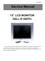
15” LCD MONITOR
DELL E156FPc
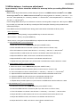
THESE DOCUMENTS ARE FOR REPAIR SERVICE INFORMATION ONLY.EVERY REASONABLE EFFORT
HAS BEEN MADE TO ENSURE THE ACCURACY OF THIS MANUAL; WE CANNOT GUARANTEE THE
ACCURACY OFTHIS INFORMATION AFTER THE DATE OF PUBLICATION AND DISCLAIMS RELIABILITY FOR
CHANGES, ERRORS OR OMISSIONS.
1
Dell E156FPc
Revision List
Revision
Release Date
Revise history
TPV model
T560KCDHK8DLNP
A00
Aug.-26-2005
Initial Release
T560KGDHK8DZNP
T560KGDHK8DENP
A01
Mar.-31-2006
A02
April-25-2006
A03
Mar.-30-2007
Add” Definition Of Pixel Defects”
Add” Max Brightness measurement”
on Page42
Add Mechanical Instruction in item 6
2
Dell E156FPc
Table of contents
Table of contents ---------------------------------------------------------------------------------------------------------------- 02
1. Monitor Specifications ------------------------------------------------------------------------------------------------------04
2. LCD Monitor Description -------------------------------------------------------------------------------------------------- 05
3. Operation instructions
--------------------------------------------------------------------------------------------------06
3.1 General Instructions
3.2 Control buttons
------------------------------------------------------------------------------------------------06
--------------------------------------------------------------------------------------------------------06
3.3 On Screen Menu/Display (OSD) ---------------------------------------------------------------------------------------07
3.4 Adjusting the Picture
-----------------------------------------------------------------------------------------------08
4. Input/Output Specification ---------------------------------------------------------------------------------------------------13
4.1 Input Signal Connector
--------------------------------------------------------------------------------------------13
4.2 Factory Preset Display Modes ----------------------------------------------------------------------------------------- 13
4.3 Power Supply Requirements ---------------------------------------------------------------------------------------- 14
4.4 Panel Specification ----------------------------------------------------------------------------------------------------- 15
5. Block Diagram
----------------------------------------------------------------------------------------------------------------17
5.1 Monitor Exploded View
5.2 Software Flow Chart
-----------------------------------------------------------------------------------------------17
----------------------------------------------------------------------------------------------------18
5.3 Electrical Block Diagram
----------------------------------------------------------------------------------------------20
6. Mechanical Instruction ------------------------------------------------------------------------------------------------------22
7. Schematic Diagram -------------------------------------------------------------------------------------------------------------27
6.1 Main Board
---------------------------------------------------------------------------------------------------------------27
6.2 Power Board ---------------------------------------------------------------------------------------------------------------32
8. Layout
------------------------------------------------------------------------------------------------------------------------ 34
8.1 Main Board ---------------------------------------------------------------------------------------------------------------- 34
8.2 Power Board -------------------------------------------------------------------------------------------------------------- 36
8.3 Key Board ----------------------------------------------------------------------------------------------------------------- 39
9. Maintainability
----------------------------------------------------------------------------------------------------------- 39
9.1 Equipments and Tools Requirement -------------------------------------------------------------------------------- 39
9.2 Trouble Shooting
------------------------------------------------------------------------------------------------------ 40
10. White Balance Adjustment
11. EDID Content
--------------------------------------------------------------------------------------------- 46
--------------------------------------------------------------------------------------------------------------- 47
12. ISP User Manual
--------------------------------------------------------------------------------------------------------- 48
12.1 Connect ISP Writer preparation action
12.2 To Use ISP Writer
---------------------------------------------------------------------- 48
------------------------------------------------------------------------------------------------ 49
12.3 Executing ISP -------------------------------------------------------------------------------------------------------------53
13. Check List
------------------------------------------------------------------------------------------------------------------- 54
14. BOM List
-----------------------------------------------------------------------------------------------------------------57
15. Definition Of Pixel Defects--------------------------------------------------------------------------------------------------68
15.1 CLAA150XP01
15.2 LM150X08
----------------------------------------------------------------------------------------------------68
----------------------------------------------------------------------------------------------------------70
3
Dell E156FPc
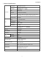
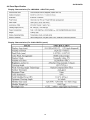
1. Monitor Specifications
Screen type
Active matrix - TFT LCD
Panel Type
LM150X08 - A5N1/TL01 (LPL)
CLAA150XP01
(CPT)
Size
380mm(15.0")
Pixel pitch
0.297mm(H) x 0.297mm(V)
Viewable angle
LM150X08 - A5N1/TL014: 65°/65° (H) 45°/55° (V) (typ.) (CR>10)
CLAA150XP01: 70°/70° (H) 60°/65° (V) (typ.) (CR>=10)
Response time
16ms(type)
Video
R, G, B Analog Interface
Separate Sync
H/V TTL
H-Frequency
30kHz – 63kHz
V-Frequency
55 - 75Hz
LCD Panel
Input
Display Colors
LM150X08 - A5N1/TL014: 16M Colors
CLAA150XP01:
16.2M Colors
Dot Clock
80MHz (Max.)
Max. Resolution
1024 x 768
Plug & Play
VESA DDC
EPA ENERGY ON Mode
STAR®
OFF Mode
<25W
Input Connector
D-Sub 15pin
Input Video Signal
Analog:0. 7Vp-p(standard)
75 OHM, Positive
Maximum Screen Size
Horizontal : 304.1mm
Vertical: 228.1mm
Power Source
100 V ~ 240 V± 10 %VAC, 50 ± 3Hz, 60 ± 3Hz
Environmental
Considerations
Operating Temp: 5° to 35°C
Operating Humidity: 10% to 80%
Storage Temp.: -20° to 60°C
Weight
Weight with packaging: 5.1 kg (14.1 lb)
<2W
4
Dell E156FPc
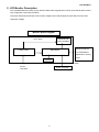
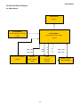
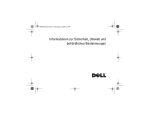
2. LCD Monitor Description
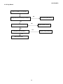
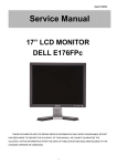
The LCD MONITOR will contain a main board, PWPC board, keypad board, which house the flat panel control
logic, brightness control logic and DDC.
The power board will provide AC to DC Inverter voltage to drive the backlight of panel and the main board
chips each voltage.
Monitor Block Diagram
Flat Panel and
CCFL Drive.
CCFL backlight
PWPC board
RS232 Connector
Main Board
For white balance
adjustment in factory
mode
Keyboard
Video signal, DDC
DC-IN
HOST Computer
100-240V
5
3. Operation instructions
3.1 General Instructions
Press the power button to turn the monitor on or off. The other control buttons are located at front panel of the
monitor. By changing these settings, the picture can be adjusted to your personal preferences.
-The power cord should be connected.
-Connect the video cable from the monitor to the video card.
-Press the power button to turn on the monitor, the power indicator will light up.
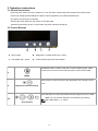
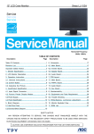
3.2 Control Buttons
A
Menu button
B
Brightness / Contrast Hotkey and - button
C
Auto Adjust and + button
D
Power On/Off button with LED Indicator
The 'MENU' button is used to open the on-screen display (OSD), select
function icons, exit from menus and sub-menus, and to exit the OSD.
A
MENU
Use this button for direct access to the 'Brightness' and 'Contrast' control
menu.
B
Brightness/Contrast Hot Key
Use these buttons to adjust (decrease/increase ranges) items in the OSD.
Note: you can activate automatic scroll feature by pressing
BC
-
and holding either + or - button.
And + buttons
6
Dell E156FPc
Use this button to activate automatic setup and adjustment. The following
dialog will appear on screen as the monitor self-adjusts to the current
input:
Auto Adjust In Progress
Auto Adjust
C
Auto Adjustment
button allows the monitor to self-adjust to the
incoming video signal. After using 'Auto Adjustment', you can further tune
your monitor by using the 'Pixel Clock' and 'Phase' controls in the OSD.
Note: Auto Adjust will not occur if you press the button while
there are no active video input signals, or attached cables.
The green LED indicates the monitor is on and fully functional. An amber
D
LED indicates DPMS power save mode.
Power Button & Indicator
The Power button turns the monitor on and off.
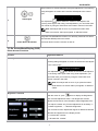
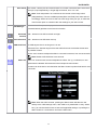
3.3 On Screen Menu/Display (OSD)
Direct-Access Functions
Function
Adjustment Method
Auto adjustment
Use this button to activate automatic setup and adjustment. The
following dialog will appear on screen as the monitor self-adjusts
to the current input:
Auto Adjust In Progress
Auto Adjustment
button allows the monitor to self-adjust to
the incoming video signal. After using 'Auto Adjustment', you
can further tune your monitor by using the 'Pixel Clock' and
'Phase' controls in the OSD.
Note: Auto Adjust will not occur if you press the button
while there are no active video input signals, or attached
cables.
Brightness / Contrast
With the menu off, push
button to display the 'Brightness'
and 'Contrast' adjustment menu. The 'Brightness' function
adjusts the luminance of the flat panel. Adjust 'Brightness' first,
then adjust 'Contrast' only if further adjustment is necessary."+"
increase 'brightness'; " - "decrease 'brightness'
The 'Contrast' function adjusts the degree of difference between
darkness and lightness on the display screen.
"+" increase the 'contrast'
"-" decrease the 'contrast'
7
Dell E156FPc
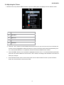
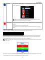
3.4 Adjusting the Picture
1. With the menu off, push the 'MENU' button to open the OSD system and display the main features menu.
A
Function icons
B
Main Menu
C
Menu icon
D
Sub-Menu name
E
Resolution
2. Push the - and + buttons to move between the function icons. As you move from one icon to another, the
function name is highlighted to reflect the function or group of functions (sub-menus) represented by that
icon. See the table below for a complete list of all the functions available for the monitor.
3. Push the 'MENU' button once to activate the highlighted function; Push -/+ to select the desired parameter,
push menu to enter the slide bar. Then use the - and + buttons, according to the indicators on the menu, to
make your changes.
4.
Push the 'Menu' button once to return to the main menu to select another function or push the 'Menu'
button two or three times to exit from the OSD.
8
Dell E156FPc
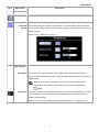
Icon
Menu Name
Description
and sub-menus
EXIT
This is used to exit out of the 'Main menu'.
Positioning:
'Positioning' moves the viewing area around on the monitor screen.
Horizontal When making changes to either the 'Horizontal' or 'Vertical' settings, no changes will
Vertical occur to the size of the viewing area; the image will simply be shifted in response to your
selection/change.
Minimum is '0' (-). Maximum is '100' (+).
Image settings:
Auto Adjust Even though your computer system can recognize your new flat panel monitor on
startup, the 'Auto Adjustment' function will optimize the display settings for use with your
particular setup.
Note: In most cases, 'Auto Adjust' will produce the best image for your
configuration; this function can be directly access via Auto Adjustment
hotkey.
Pixel Clock The 'Phase' and 'Pixel Clock' adjustments allow you to more closely adjust your monitor
to your preference. These settings are accessed through the main OSD menu, by
selecting 'Image Settings'.
Use the - and + buttons to adjust away interference. Minimum: 0 ~ Maximum: 100
9
Dell E156FPc
Phase If satisfactory results are not obtained using the 'Phase' adjustment, use the 'Pixel Clock'
adjustment and then use 'Phase' again.
Note: This function may change the width of the display image. Use the
'Horizontal' function of the 'Position' menu to center the display image on the
screen.
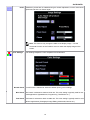
Color Settings:
'Color Settings' adjusts the color temperature and saturation.
Normal Preset 'Normal Preset' is selected to obtain the default (factory) color settings.
Blue Preset 'Blue Preset' is selected to obtain a bluish tint. This color setting is typically used for text
based applications (Spreadsheets, Programming, Text Editors etc.).
Red Preset 'Red Preset' is selected to obtain a redder tint. This color setting is typically used for color
intensive applications (Photograph Image Editing, Multimedia, Movies etc.).
10
Dell E156FPc
User Preset 'User Preset': Use the plus and minus buttons to increase or decrease each of the three
colors (R, G, B) independently, in single digit increments, from '0' to '100'.
Note: 'Color temperature' is a measure of the 'warmth' of the image colors
(red/green/blue). The two available presets ('Blue' and 'Red') favor blue and red
accordingly. Select each one to see how each range suits your eye; or utilize the
'User Preset' option to customize the color settings to your exact choice.
OSD Settings:
Each time the OSD opens, it displays in the same location on the screen. 'OSD Settings'
(horizontal/vertical) provides control over this location.
Horizontal - and + buttons move OSD to the left and right.
Position
Vertical Position - and + buttons move OSD down and up.
OSD Hold Time: The OSD stays active for as long as it is in use.
'OSD Hold Time': Sets the length of time the OSD will remain active after the last time
you pressed a button.
Use the - and + buttons to adjust the slider in 5 second increments, from 5 to 60 seconds.
Note: Default 'OSD hold time' is 20 seconds.
OSD Lock 'OSD Lock': Controls user access to adjustments. When 'Yes' (+) is selected, no user
adjustments are allowed. All buttons are locked except the menu button.
All buttons can be locked or unlocked when the 'Menu' button is pushed and held for over
15 seconds.
Note: When the OSD is locked, pressing the 'Menu' button will take the user
directly to the 'OSD settings' menu, with 'OSD Lock' preselected on entry. Select
'No'(-) to unlock and allow user access to all applicable settings; or pressing the
'Menu' button for 15 seconds to unclock the OSD menu.
11
Dell E156FPc
Language:
Language sets the OSD to display in one of five languages (English, Español, Français,
Deutsch, Japanese).
Note: The language chosen affects only the language of the OSD. It has no
effect on any software running on the computer.
Factory Reset:
'Factory Reset' returns the settings to the factory preset values for the selected group of
functions.
‘Exit’ is used to exit out of 'Factory Reset' menu.
For 'All settings', all user adjustable settings are reset at one time except 'Language
settings'.
OSD Warning Messages
A warning message may appear on the screen indicating that the monitor is out of sync.
Cannot Display This Video Mode
Optimum resolution 1024X768 60 Hz
This means that the monitor cannot synchronize with the signal that it is receiving from the computer. Either the
signal is too high or too low for the monitor to use. See Specifications for the Horizontal and Vertical frequency
ranges addressable by this monitor. Recommended mode is 1024 X 768 @ 60Hz.
Note: The floating 'Dell - self-test Feature Check' dialog will appear on-screen if the monitor cannot sense a
video signal.
Occasionally, no warning message appears, but the screen is blank. This could also indicate that the monitor is not
synchronizing with the computer. See Troubleshooting for more information.
12
Dell E156FPc
4. Input/Output Specification
4.1 Input Signal Connector
Pin NO.
Description
Pin NO.
Description
1.
Red Video
9.
+5V
2.
Green Video
10.
Logic Ground
3.
Blue Video
11.
RXD
4.
TXD
12.
DDC-Serial Data
5.
Detector Pin
13.
H-Sync
6.
R-Ground
14.
V-Sync
7.
G-Ground
15.
DDC-Serial Clock
8.
B-Ground
VGA Connector layout
1
5
6
10
11
15
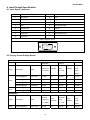
4.2 Factory Preset Display Modes
VESA MODES
Horizontal
Mode
Resolution
Total
Vertical
Nominal
Sync
Nominal
Sync
Nominal
Frequency
Polarity
Freq.
Polarity
Pixel
+/- 0.5kHz
+/- 1 Hz
Clock
(MHz)
VGA
XGA
640x480@60Hz
800 x 525
31.469
N
59.940
N
25.175
640x480@75Hz
840 x 500
37.500
N
75.00
N
31.500
800x600@60Hz
1056 x 628
37.879
P
60.317
P
40.000
800x600@75Hz
1056x625
46.875
P
75.000
P
49.500
1024x768@60Hz
1344x806
48.363
N
60.004
N
65.000
1024x768@75Hz
1312x800
60.023
P
75.029
P
78.750
IBM MODES
Nominal
Mode
Resolution
Total
Frequency
+/- 0.5kHz
DOS
720x400@70Hz
900 x 449
31.469
13
Sync
Polarity
N
Nominal
Freq.
+/- 1 Hz
70.087
Nominal
Sync
Pixel
Polarity
Clock
(MHz)
P
28.322
Dell E156FPc
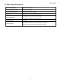
4.3 Power Supply Requirements
A/C Line voltage range
100 V ~ 240 V± 10 %
A/C Line frequency range
50 ± 3Hz, 60 ± 3Hz
Input Voltage transients
280 volts AC for 10 sec @40℃
Current
0.6A max, at 100V, 0.35A max, at 240 V
< 60A peak at 240 VAC and cold starting
Peak surge current
< 30A peak at 120VAC and cold starting
Leakage current
< 3.5mA
No advance effects (no loss of information or defect)
Power line surge
with a maximum of 1 half-wave missing per second
14
Dell E156FPc
4.4 Panel Specification
Display Characteristics (For LM150X08 - A5N1/TL01 panel)
Display Characteristics (For CLAA150XP01 panel)
15
Dell E156FPc
4.4.2 Optical Characteristics (For LM150X08 - A5N1/TL01 panel)
Measured conditions as follows: Ta=25±2°C, VLCD=3.3V,Fv=60Hz,Dclk=65MHz,Llamp=8mA.
Optical Characteristics (For CLAA150XP01 panel)
16
Dell E156FPc
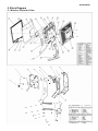
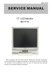
5. Block Diagram
5.1 Monitor Exploded View
17
Dell E156FPc
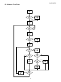
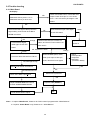
5.2 Software Flow Chart
1
Y
2
3
N
4
N
5
Y
6
N
7
8
Y
9
N
10
11
Y
N
12
13
Y
14
Y
15
Y
17
18
N
19
Y
18
N
N
16
Dell E156FPc
1) MCU Initializes.
2) Is the EEprom blank?
3) Program the EEprom by default values.
4) Get the PWM value of brightness from EEprom.
5) Is the power key pressed?
6) Clear all global flags.
7) Are the AUTO and SELECT keys pressed?
8) Enter factory mode.
9) Save the power key status into EEprom.
Turn on the LED and set it to green color. Scalar
initializes.
10) In standby mode?
11) Update the lifetime of back light.
12) Check the analog port, are there any signals coming?
13) Does the scalar send out an interrupt request?
14) Wake up the scalar.
15) Are there any signals coming from analog port?
16) Display "No connection Check Signal Cable" message. And go into standby mode after the message
disappears.
17) Program the scalar to be able to show the coming mode.
18) Process the OSD display.
19) Read the keyboard. Is the power key pressed?
19
Dell E156FPc
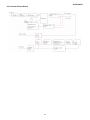
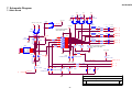
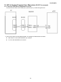
5.3 Electrical Block Diagram
5.3.1 Main Board
LCD Interface
(CN101)
Flash Memory
SST25VF020-20- 4C-SAE
Scalar GM2621
(U402)
(Include MCU, ADC, OSD)
(U401)
R
EPR_SDA
RXD
EPR_SCL
TXD
G
B
OSD Control Interface
EEPROM
D-Sub
(CN403)
M24C16-MN6T
Connector
(U403)
(CN405)
20
H
V
DB15_SDA,
DB15_SCL
EEPROM (U404)
M24C02WMN6
Dell E156FPc
5.3.2 Inverter/Power Board
21
Dell E156FPc
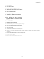
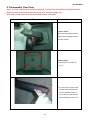
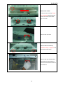
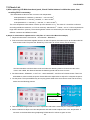
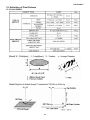
6. Disassembly Flow Chart
Tools: 2 Power screwdrivers (φ=5mm,L=60mm); 1 small cross screwdriver; turnbuckle driver;
Setting: Power screwdriver torque A=11 kgF. Cm; torque B=6 kgF. Cm
Note: Firstly, put the monitor on a soft, flat and clean surface, wear gloves.
Fig
Remark
Remove stand:
Press the Stand release button
and lift up the Stand and away
from the monitor.
Remove bezel:
1. Remove the 4 screws by
torque A
2. Pry the monitor up then find
out the hooks’ position, use
the tool (like the picture or
other card) to insert into the
gap of bezel and rear cover.
22
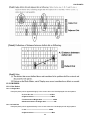
Dell E156FPc
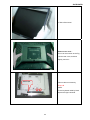
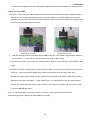
3. Take off the bezel
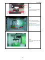
Remove rear cover :
Turn over the monitor as the Fig,
hold the rear cover, and then
slightly remove it.
Black tape
Remove the two screws by
Torque B
Install:
Fix the keyboard cable by black
tape as the figure showed.
23
Dell E156FPc
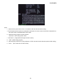
Remove the shield :
1. Remove the screw by Torque
B or by manual and remove the
shield ,then remove the back
light connector
Remove the connector
Remove the two screws by
manual or torque = 3kgF.Cm and
remove the main frame
Remove the main frame and at
the same time disconnect the
LVDS connector and remove the
EVA washers
24
Dell E156FPc
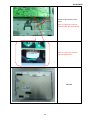
EVA washers
Install:
Fix the LVDS connector by black
tape and EVA washers.
Black tape
LVDS Cable
Remove the eight screws by
Torque B and remove the power
board and main board.
Note: Magnetism ring should be
laid at the right of power board
Magnetism ring
Install:
Fix the LVDS cable by black tape
as the figure.
25
Dell E156FPc
ground
Screw AC ground line as the
figure.
Note: The green line can’t be
pressed under the power board.
Note: The pins can’t gore the
blue and purple lines.
The end
26
Dell E156FPc
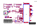
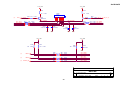
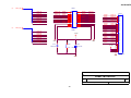
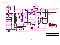
7. Schematic Diagram
7.1 Main Board
+5V
+5V
GND
2
1
1
2
1
GND
2
C448
NC
C447
NC
SPI_3V3
+5V
C439
0.1uF/16V
GND
D402
NC 1
3
1
2
2
D404
BAV99
3
D403
BAV99
3 SPI_3V3
3
VGA_5V +3.3V_VDD
D405
BAV99
FB410
(10 mil, ┰キ︽絬)
VGA_5V
1
60 OHM
D407
Pins 6/7/8 are R/G/B
return lines resp.
4.7K 1/16W
4.7K 1/16W
GND
R454
220 1/16W
VCC
WP
SCL
SDA
12
13
14
15
8
7
6
5
Rin
2 R435
75 1/16W
R442
100 1/16W
C433
2 R436
75 1/16W
R443
100 1/16W
C434
C436
0.047uF
C437
Gin
1
Bin
60 OHM
R438
75 1/16W
R445
220 1/16W
GND
0.047uF
GREEN+(3)
0.047uF
GREEN- (3)
C438
0.047uF
BLUE+
(3)
BLUE-
(3)
0.047uF
75-ohm terminating resistor
very close to the VGA
conn.
GND
LL5232B 5.6V 5%
D411
LL5232B 5.6V 5%
D412
GND
DDC_SCL_VGA
(3)
D406
LL5232B 5.6V 5%
D410
LL5232B 5.6V 5%
R444
10K 1/16W
VGA_PLUG
GND
GND
R446
220 1/16W
R447
220 1/16W
CABLE_DET (3)
(8 mil)
R455
220 1/16W
D409
R448
2.2K 1/16W
D408
R449
2.2K 1/16W
C442
NC
LL5232B 5.6V 5%
EDID_WP
(3)
R439 R440
M24C02WMN6
EDID_WP
(3)
RED-
+3.3V_VDD
GND
(3)
RED+
0.047uF
FB412
16
A0
A1
A2
GND
R453
220 1/16W
HS_in
VS_IN
U404
1
2
3
4
17
3
DDC_SDA_A
60 OHM
DB15
1
6
2
7
3
8
4
9
5
10
11
R451
1
CN405
75 1/16W
R452
C444
0.1uF/16V
(3)
DDC_SDA_VGA
4.7K 1/16W
R450
C432
FB411
75 1/16W
BAT54C
2 R434
75 1/16W
R441
100 1/16W
VS
(3)
HS
(3)
C443
NC
LL5232B 5.6V 5%
GND
Title
Input Connectors
Size
A
Date:
27
Document Number
Rev
D
Wednesday, June 29, 2005
Sheet
2
of
6
Dell E156FPc
3.3V_PVDD
3.3V_AVDD
3.3V_LAVDD
3.3V_DVDD
1.8V_DVDD
1.8V_AVDD
FB404
120OHM
C410
C409
22uF/16V
+
C411
0.1uF/16V
C412
C413
C414
0.1uF/16V 0.1uF/16V 0.1uF/16V 0.1uF/16V
Close to respective power Pins
GND
3.3V_PVDD
Close to respective power Pins
GND
1.8V_DVDD
C417
C418
C445
C446
+
C416
FB406
120OHM
C424
0.1uF/16V 0.1uF/16V 0.1uF/16V 0.1uF/16V
FB405
120OHM
C420
+
C419
22uF/16V
0.1uF/16V
C421
C422
106
104
86
78
70
118
87
55
17
53
91
116
2
25
47
128
82
74
GPIO_8
GPIO_9
GPIO_10
GPIO_11
GPIO_12
GPIO_13
GPIO_14
3.3V_AVDD
FB402
120OHM
VDD_RPLL_18
C407
AVDD_ADC_18
C406
AVDD_DVI_18
AVDD_DVI_18
AVDD_DVI_18
C405
CVDD_18
CVDD_18
CVDD_18
CVDD_18
C404
RVDD_33
RVDD_33
LBADC_VDD_33
C403
0.1uF/16V 0.1uF/16V 0.1uF/16V 0.1uF/16V 0.1uF/16V 0.1uF/16V
VDD_OUT_33
VDD_OUT_33
VDD_OUT_33
C402
+
C401
22uF/16V
AVDD_BIAS_33
FB401
120OHM
AVDD_RPLL_33
1.8V_AVDD
AVDD_DVI_33
AVDD_DVI_33
110
+1.8V_VDD
AVDD_ADC_33
AVDD_ADC_33
3.3V_DVDD
101
92
+3.3V_VDD
120
121
122
123
124 R430
125 NC
126
NVRAM_SCL
NVRAM_SDA
/WP
POWER_ON
ROM_WP#
LED_O
LED_G
(4)
(4)
(4)
C423
0.1uF/16V 0.1uF/16V 0.1uF/16V 0.1uF/16V
22uF/16V
to respective power Pins
GND
GND
C427
33pF
3.3V_PVDD
X401
FB403
120OHM
14.318MHz
C426
+
C425
22uF/16V
+5V
XTAL
TCLK
VCC
RSTN
GND
3
2
GND
1
1
SPI_3V3
+3.3V_VDD
R418
NC
NC
111
63
C441
0.1uF/16V
64
65
(2) DDC_SCL_VGA
(2) DDC_SDA_VGA
2
RED+
REDGREEN+
GREENBLUE+
BLUE-
E_CLK_N
E_CLK_P
HSYNC
VSYNC
RESERVED
RESERVED
RESERVED
RESERVED
RESERVED
RESERVED
RESETn
R419
0 1/16W
R422
10K 1/16W
GND
GND
1
89
90
HS
VS
RESETn
NC
3
CN402
99
100
96
97
93
94
RED+
REDGREEN+
GREENBLUE+
BLUE(2)
(2)
R456
NC
Q402
C429
NC
+5V
R428
NC
R421
5.6K 1/16W
ROM_WP#
2
OPTIONAL
FOR
DEBUGGING
PURPOSES
ONLY
NC
R437
NC
3
U405
R431 NC
HOLD#
C440
E_CH2_N
E_CH2_P
E_CH1_N
E_CH1_P
E_CH0_N
E_CH0_P
C428 33pF
(2)
(2)
(2)
(2)
(2)
(2)
R433
NC
GND
UDART_DO
UDART_DI
109
3.3V_PVDD
RESERVED
RESERVED
RESERVED
RESERVED
E_CH3_N
E_CH3_P
0.1uF/16V
+5V
1
2
3
4
108
R400
R401
GND
NC
NC
66
67
GND
RESERVED
RESERVED
RESERVED
RESERVED
RESERVED
O_CH3_N
O_CH3_P
DDC_SCL_VGA
DDC_SDA_VGA
DDC_SCL_DVI
DDC_SDA_DVI
O_CH2_N
O_CH2_P
O_CH1_N
O_CH1_P
O_CH0_N
O_CH0_P
GND
72
73
75
76
80
81
83
84
G-PROBE
3.3V_DVDD
3.3V_AVDD
RX2+
RX2RX1+
RX1RX0+
RX0RXC+
RXC-
U401
gm2621
O_CLK_N
O_CLK_P
MQFP-128
O_BON
RESERVED
RESERVED
RESERVED
RESERVED
RESERVED
+3.3V_VDD
249 1/16W
R402
C431
69
R406 R407 R408
REXT
58
UDART_DI
57
56
59
+3.3V_VDD
UART on GPO
UART on DDC
Open
V_EDID_ATMEL
(SPI_CSn)
ATMELSPI ROM
Standard SPI ROM
Open
Ext. ROM JTAG Off
ROM_WP#
1
2
3
4
GND
CE# VDD
SO HOLD#
WP# SCK
VSS
SI
8
7
6
5
GND
HOLD#
ROM_SCLK
ROM_SDI
SST25VF020-20-4C-SAE
R429
10K 1/16W
GND
C435
0.1uF/16V
GND
LVDS_E[0..9]
27
28
29
30
31
32
LVDS_O8
LVDS_O9
35
36
37
38
39
40
LVDS_O4
LVDS_O5
LVDS_O2
LVDS_O3
LVDS_O0
LVDS_O1
33
34
LVDS_O6
LVDS_O7
41
42
43
44
45
46
127
49
LVDS_O[0..9]
R476
NC
R477
PPWR GND
PBIAS
LVDS_O[0..9]
(5)
(5)
+3.3V_VDD
PPWR
PBIAS
(6)
(6)
105
GPO_0
SPI_CSn
R416
4.7K 1/16W
60
61
62
LBADC_IN1
LBADC_IN2
LBADC_IN3
LBADC_VSS
SPI_CLK
SPI_DI
SPI_DO
115
114
113
112
LBADC1
LBADC2
CABLE_DET
(4)
(4)
(2)
GND
18
CRVSS
54
CRVSS
88
117 CRVSS
CRVSS
R423
4.7K 1/16W
U402
UART_PIN_SEL
(PWM1)
GPO_0
R432
4.7K 1/16W
R417
AVSS_DVI
AVSS_DVI
AVSS_DVI
AVSS_DVI
Open
R426 R427
VBUFC_RPLL
68
71
77
79
Standard SPI ROM
Default
4.7K 1/16W
ATMELSPI ROM
Open
4.7K 1/16W
ATMEL_EN
(PWM0)
10 KOhm
4.7K 1/16W
Name
LVDS_E[0..9]
GPO_1
AVSS_BIAS
EDID_WP
Boot-Strap Configuration:
GPO_2
85
103 AVSS_DVI
AVSS_ADC
(2)
GND
51
EDID_WP
LVDS_E6
LVDS_E7
19
20
21
22
23
24
GPO_3
VSS_OUT
VSS_OUT
+3.3V_VDD
9
10
PWM0 / GP0_4
1
GND
UDART_DO
26
48
R424
4.7K 1/16W
LVDS_E4
LVDS_E5
LVDS_E2
LVDS_E3
LVDS_E0
LVDS_E1
PWM1 / GPO_5
VSS_RPLL
R425
50
(6) BRIGHTNESS
M24C16-MN6T
PPWR
PBIAS
119
LVDS_E8
LVDS_E9
11
12
13
14
15
16
CRVSS
GND
107
100 1/16W /WP
100 1/16W NVRAM_SCL
100 1/16W NVRAM_SDA
GND
95
AVSS_ADC
98
102 AVSS_ADC
AVSS_ADC
R409
R410
R411
NC R404
8
7
6
5
52
0.1uF/16V
4.7K 1/16W
VCC
WC
SCL
SDA
4.7K 1/16W
A0
A1
A2
VSS
4.7K 1/16W
1
2
3
4
4.7K 1/16W
U403
NC R403
C430
0.1uF/16V
3
4
5
6
7
8
4.7K 1/16W
3.3V_LAVDDClose
GND
Title
gm2621
GND
Size
Document Number
Custom
Date:
28
Wednesday, June 29, 2005
Rev
D
Sheet
3
of
6
Dell E156FPc
+3.3V_VDD
+3.3V_VDD
R457
R458
100 1/16W
100 1/16W
CN403
CONN
R459 47K 1/16W
LED_G
LED_G
Q401
PMBS3904
R461
R463
R465
220 1/16W
220 1/16W
220 1/16W
R462
R464
C454
0.1uF/16V
C455
0.1uF/16V
GND
10K 1/16W
220 1/16W KEY_MENU
220 1/16W KEY_LEFT
GND
C456
0.1uF/16V
GND
C457
0.1uF/16V
GND
GND
+3.3V_VDD
R466
LED_O (3)
LED_ORANGE
LED_GREEN
KEY_AUTO
KEY_RIGHT
KEY_ONOFF
R460
47K 1/16W LED_O
Q403
PMBS3904
8
7
6
5
4
3
2
1
(3)
+3.3V_VDD
R467
R468
10K 1/16W
10K 1/16W
C458
0.1uF/16V
GND
(3)
LBADC1
R469
R470
30K 1/16W
22K 1/16W
KEY_MENU
KEY_RIGHT
(3)
LBADC2
R472
R471
30K 1/16W
22K 1/16W
KEY_LEFT
KEY_AUTO
(3)
POWER_ON
R474
4.7K 1/16W
KEY_ONOFF
Title
KEYPAD
Size
A
Date:
29
Document Number
Rev
D
Wednesday, June 29, 2005
Sheet
4
of
6
Dell E156FPc
LVDS_O[0..9]
CN101
LVDS_O0
LVDS_O1
LVDS_O2
LVDS_O3
LVDS_O4
LVDS_O5
LVDS_O6
LVDS_O7
LVDS_O8
LVDS_O9
(3)
LVDS_O0
LVDS_O2
LVDS_O4
LVDS_O6
LVDS_O8
LVDS_E0
LVDS_E2
LVDS_E4
LVDS_E6
LVDS_E8
RXO0RXO1RXO2RXOCRXO3RXE0RXE1RXE2RXECRXE3-
2
4
6
8
10
12
14
16
18
20
22
24
1
3
5
7
9
11
13
15
17
19
21
23
RXO0+
RXO1+
RXO2+
RXOC+
RXO3+
RXE0+
RXE1+
RXE2+
RXEC+
RXE3+
LVDS_O1
LVDS_O3
LVDS_O5
LVDS_O7
LVDS_O9
LVDS_E1
LVDS_E3
LVDS_E5
LVDS_E7
LVDS_E9
CN102
LVDS_E[0..9]
CONN
LVDS_E0
LVDS_E1
LVDS_E2
LVDS_E3
LVDS_E4
LVDS_E5
LVDS_E6
LVDS_E7
LVDS_E8
LVDS_E9
+VLCD
15.4mA
(3)
GND
C101
+
GND
R101
RXO0+
RXO0RXO1+
RXO1RXO2+
RXO2-
LVDS_O1
LVDS_O0
LVDS_O3
LVDS_O2
LVDS_O5
LVDS_O4
RXOC+
RXOCRXO3+
RXO3RXE0+
RXE0-
LVDS_O7
LVDS_O6
LVDS_O9
LVDS_O8
LVDS_E1
LVDS_E0
RXE1+
RXE1-
LVDS_E3
LVDS_E2
RXE2+
RXE2RXEC+
RXECRXE3+
RXE3-
LVDS_E5
LVDS_E4
LVDS_E7
LVDS_E6
LVDS_E9
LVDS_E8
C102
+VLCD
22uF/16V
0.1uF/16V
4.7K 1/16W
30
29
28
27
26
25
24
23
22
21
20
19
18
17
16
15
14
13
12
11
10
9
8
7
6
5
4
3
2
1
CON30/NC
GND
GND
Title
PANEL INTERFACE
Size
A
Date:
30
Document Number
Rev
D
Wednesday, June 29, 2005
Sheet
5
of
6
Dell E156FPc
+12V
+5V
CN701
ON_OFF
DIM
VCC12V
GND
VCC5V
GND
2
4
6
8
10
12
1
3
5
7
9
11
4.7K 1/16W
R705
PBIAS
(3)
+5V
D704
FB701
NC
+3.3V_VDD
SR24
U701 AIC1084-33PM
3
R708
+
C701
C703
0.1uF/16V
22uF/16V
1K 1/16W
ADJ
C708
+
GND
2
VOUT
VIN
C702
C704
0.1uF/16V
1
0.1uF/16V
GND
C706
0.1uF/16V
C707
+5V
100uF/16V
CON402(PITCH 2.00)
GND
100uF/16V
GND
GND
VCC12V
GND
VCC5V
GND
GND
GND
+
GND
R710
GND
1K 1/16W
R707
Q703
PMBS3904
(3) BRIGHTNESS
1K 1/16W
C711
+
FB702
120OHM
22uF/16V
+5V
+1.8V_VDD
GND
D702
NC
U702
3
+5V
+3.3V_VDD
3
47K 1/16W
R723
+
AO3401L
R721
0 1/16W
R722
NC
47K 1/16W
C715 2
Q706
PMBS3904
0.1uF/16V
R725
(3) PPWR
47K 1/16W
C710
22uF/16V
Q704
1
C712
GND
GND
0.1uF/16V
R714
VI
VO
2
C709
GND
C713
0.1uF/16V
D701
NC
100uF/16V
+VLCD
GND
+5V
1
GND
+
GND
GND
C718
0.1uF/16V
+
C717
22uF/16V
Title
GND
POWER
GND
Size
A
Date:
31
Document Number
Rev
D
Wednesday, June 29, 2005
Sheet
6
of
6
Dell E156FPc
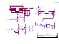
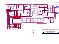
7.2 Power Board
4
R921
47 1/2W
C921
0.001uF/500V
3
3
1
R903
5.1K 1/8W
+
R905
5.1K 1/8W
C906
10uF
1
1
R909
68 1/10W
1
5
NCP1203DR60
4
C903 0.47uF/250V
11
+5V
2
3
+ C924
1000uF/16V
+
C926
470uF/16V
R926
NC
D922
FMB26L
7
R927
NC
C928
0.1uF
Q901
STP9NK60ZFP
R917
10K 1/10W
R916
220 1/10W
C900
0.001uF/250V
3
R923
560 1/4W
2
7
R911
20K 1/10W
2
L
6
8
IC901
NCP1203DR
12
1O
R920
NC
R915
22 1/10W
R910
4.7K 1/10W
6
R918
0.39 2W
2
C907
0.1uF
C901
0.001uF/250V
L
ZD903
PTZ7.5B
3
L904
D902
UF4003
1
+ C925
470uF/25V
R922
C922
47 1/2W 0.001uF/500V
R907
NC
C902
0.001uF/250V
2
+ C931
1000uF/25V
O8
R904
5.1K 1/8W
4
L901
+12V
+ C923
1000uF/25V
9
D901
FR107
4
3
F902
0 1/8W
L
1
3
L902
L
1
R908
100K 2W
C905
0.0015uF/2KV
C904
100uF/450V
+
2
R906
NC
L903
2
10
2
-
T901
4
O
D921
FMB29L
2
+
DB901
KBP206G
2
ZD904
RLZ13B
ZD905
RLZ5.1B
1
R929
R930
33K 1/10W 3.6K 1/10W
D923
LL4148-GS08
NR901
NTCR
t
4
IC902
PC123FY2 4P
3
C932
0.47uF/25V
D924
LL4148-GS08
CN902
CONN
R924
1K 1/10W
1
2
3
4
5
6
7
8
2
2
ZD902
RLZ5.1B
1
R900
220K 1/8W
2
R902
220K 1/8W
C911
470pF/50V
1
C912
0.001uF
1
220K 1/8W
R901
1
varistor
R914
4.7K 1/10W
Q902
2PA733P
1
VAR901
2
ZD901
RLZ15B
F901
FUSE
D903
LL4148-GS08
C929
0.1uF
R912
100 1/10W
IC903
AZ431AZ-AE1
Q903
2PC945P
R913
75K 1/10W
+
C908
22uF
R919
16K 1/10W
C930
NC
DIM
+12V
+5V
C927
0.1uF
R932
1K 1/10W
R933
2.4K 1/10W
1
2
3
C933
0.001uF/250V
R925
0 1/8W
R931
1K 1/10W
ON/OFF
CN901
CONN
AOC (Top Victory) Electronics Co., Ltd.
Title
32
1.POWER OUTPUT 12V & 5 V
Size
B
Document Number
Date:
Wednesday, March 09, 2005
Rev
PWPC1742SEI1 (715L1492-E)
Sheet
1
A
of
2
Dell E156FPc
L201
470uF/25V
C202
0.1uF/25V
120UH
R221
R222
R223
R224
2.4K 1/4W2.4K 1/4W2.4K 1/4W2.4K 1/4W
ZD201
RLZ11B
R202
220 1/10W
C205 1uF/25V
D201
RB050L-40
R214
15K 1/10W
ON/OFF
R211
NC
1
R210
47K 1/10W
6
10
C210
1uF/25V
C212
NC
CN202
CONN
O
R206
12K 1/10W
9
Q205
PMBS3906
R212
62K 1/10W
C211
NC
8-3
C221
0.33uF/250V
R203
3.9K 1/10W
+
DIM
1
2
O
R205
15K 1/10W
PMBS3904
C209
4.7uF/16V
11
O
Q204
R213
4.7K 1/10W
CN201
CONN
PT201
1
Q201
DTC144WKA
Q203
IRF5305S
R201
3.9K 1/10W
C204
NC
1
+ C203
TP2
HVO
1
Q202
DTA144WKA
1
C201
0.1uF/25V
TP1
HVO
2
2
3
+12V
Q206
2SC5706-PM-E
R204
470 1/10W
12
1
2
POWER X'FMR
Q207
2SC5706-PM-E
9
D203
LL4148-GS08
R229
12K 1/10W
C222
1uF/25V
R228
560 1/10W
D202
LL4148-GS08
R225
1K 1/8W
D205
LL4148-GS08
D204
LL4148-GS08
R226
1K 1/8W
GND
OUT1
R227
680 1/10W
8
7
FB1
INV1
DT1
6
5
4
D206
LL4148-GS08
VCC
10
OUT2
11
DT2
12
FB2
13
INV2
14
NON2
15
RT
NON1
3
CV
2
C207
330pF
R230
51K 1/10W
C223
0.47uF/25V
1
C206
NC
SCP
TL1451ACNSR
IC201
VREF
16
C208
0.1uF/25V
R207
10K 1/10W
R208 0 1/10W
R209 0 1/10W
AOC (Top Victory) Electronics Co., Ltd.
is power GND
is signal GND
Title
Rev
PWPC1521LGD2(715L)
Date:
33
2.FOR 2 LAMP INVERTER
Size
Document Number
Custom
Wednesday, March 02, 2005
Sheet
A
2
of
2
Dell E156FPc
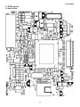
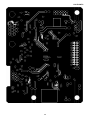
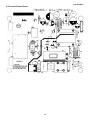
8. PCB Layout
8.1 Main Board
34
Dell E156FPc
35
Dell E156FPc
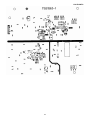
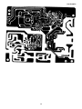
8.2 Inverter/Power Board
36
Dell E156FPc
37
Dell E156FPc
38
Dell E156FPc
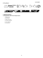
8.3 Key Board
9. Maintainability
9.1 Equipments and Tools Requirement
1. Voltage meter
2. Oscilloscope
3. Pattern Generator
4. LCD Color Analyzer
5. Service Manual
6. User Manual
39
Dell E156FPc
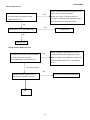
9.2 Trouble shooting
9.2.1 Main Board
No display
Check main board Power; is there DC level
output? Check U701 pin 2= 3.3V? U702
pin 2= 1.8V? Is there any shortage or cold
solder?
NG
Measured CN701 pin5/6 = 12 V?
Measured CN701 pin 9/10= 5V?
OK
Disconnected the Signal cable (Loose the
Signal cable), Is the screen show Block
Connected the Signal cable again,
OK
Green
check LED status.
WRGB color bars?
NG
Orange
Check Power switch is in Power-on
Replace U401
Connected the Signal
status, and check if Power switch had
cable again Check LED
been stuck?
Scalar IC
status.
OK, Keyboard no stuck
Orange
Green
Check the Wire-Harness from CN101
Measured RGB (R434, R435,
R436,) H/V Input at U401 pin
89,90, Was there have signal?
OK, Wire tight enough
Check Panel-Power Circuit Block
NG
OK
OK, Panel Power OK
Measured Crystal X401
Check U401 Data-output Block
OK, U401 data OK
Replace Inverter board and Check
Check
Correspondent
component
short/open
(Protection Diode)
OK
Replace U401 (GM2621)
Inverter control relative circuit
OK
Re-do White balance adjust
Note: 1. If replace “Main-Board”, Please re-do “DDC-content” programmed & “White-Balance”.
2. If replace “Power Board” only, Please re-do “ White-Balance”
40
Dell E156FPc
Panel Power Circuit
Check the PPWR panel power relative circuit,
Check C101 should have response from
NG
Q704, Q706; in normal operation,
0V to 5V when we switch the power
When LED =green, V-R725 should =5V
switch from on to off
If PPWR no-response when the power switch
Turn on and turn off, replace the U401
OK
NG
Check CN101, if it is not soldered well
Change CN101
OK
Change panel
Inverter Control Relative Circuit
NG
Check the BKlt-On relative circuit, R705; in
Measured the inverter connector CN402
normal operation, when LED=green, R705
Pin2 on/off control=3.3V (on)
BKlt-On should=3.3V, If BKlt-On no-response
Pin4 PWM signal control dim 0V-5V
when the power switch turn on-off, Replace
U401
NG, still no screen
NG
Replace Inverter board to new-one
Check NO SCREEN APPEAR block
And check the screen is normal?
OK
41
Dell E156FPc
U401-data Output
Check GM2621 (U401)
NG
Signal output (PIN 7 -16, PIN 31 - 40)
Replace GM2621 (U401) or
replace Main board.
Is the waveform ok?
OK
If Main Board being replaced, please
Replace panel
do the DDC – content reprogrammed,
and do the white balance adjustment
42
Dell E156FPc
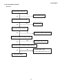
9.2.2 Inverter/Power Board
No Power
Check to CN701 Pin2=12V
NG
Check Interface board
OK
Check AC line volt 110V or 220V
NG
Check AC line
OK
Check the voltage of C904(+)
NG
Check F901, bridge rectified circuit
OK
Check start voltage for the pin8 of IC901
NG
Check R903, R904, IC901
OK
Check the auxiliary voltage is between 10V-16V
NG
1) Check IC902, IC903
OK
2) Check Q902, Q903 OVP circuit
Check D921, D922
43
Dell E156FPc
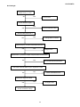
No Backlight
Check C201 (+) =12V
OK
NG
Check F902
Check ON/OFF signal
OK
NG
Check Interface board
Check IC201 pin9=12V ?
OK
NG
Change Q201 or Q202
Check the pin1 of IC201 have saw tooth wave
OK
NG
Change IC201
Check D201 (-) have the output of square wave at short time.
OK
NG
Check Q203/Q204/Q205/D201
Check the resonant wave of pin1 & pin6 for PT201
OK
NG
Check Q206/Q207/C221
Check the output of PT201
OK
NG
Change PT201
Check connecter & lamp
44
Dell E156FPc
9.2.3 Key Board
OSD is unstable or not working
NG
Is Keypad board connecting normally?
Connect Keypad Board
OK
Is Button Switch normally?
NG
Replace Button Switch
OK
NG
Is Keypad board normally?
Replace Keypad Board
OK
Check main board
45
Dell E156FPc
10.White balance, Luminance adjustment
Approximately 2 Hours should be allowed for warm up before proceeding White-Balance
adjustment.
Before started adjust white balance, please setting the Chroma-7120 MEM. Channel 3 to 65000K colors, MEM.
Channel 4 to 93000K colors, MEM. Channel 9 to 57000K (our 9300 parameter is x=283±28, y=297±28, Y = 175
±20 cd/m2, 6500 parameter is x =313±28, y=329±28, Y = 180 ±20 cd/m2, and 5700 parameter is x = 328 ±28, y =
344 ±28, Y = 180 ±20 cd/m2)
How to setting MEM.channel you can reference to chroma 7120 user guide or simple use “ SC” key and “ NEXT”
key to modify xyY value and use “ID” key to modify the TEXT description Following is the procedure to do
white-balance adjust
Press MENU and AUTO-ADJUST button during press Power button will activate the factory mode,
Gain adjustment:
Move cursor to “-Factory Setting-” and press MENU key to enter this sub-menu.
Move cursor to “ Factory” and press MENU key.
Move cursor to “ Auto Level” and press MENU key to adjust Gain and Offset automatically;
a. Adjust sRGB (65000K) color-temperature
1. Switch the chroma-7120 to RGB-mode (with press “MODE” button)
2. Switch the MEM.channel to Channel 3 (with up or down arrow on chroma 7120)
3.The LCD-indicator on chroma 7120 will show x = 313 ±28, y = 329 ±28, Y = 180 ±20 cd/m2
4. Adjust the RED on OSD window until chroma 7120 indicator reached the value R=100
5. Adjust the GREEN on OSD, until chroma 7120 indicator reached G=100
6. Adjust the BLUE on OSD, until chroma 7120 indicator reached B=100
7. Repeat above procedure (item 5,6,7) until chroma 7120 RGB value meet the tolerance =100±2
b. Adjust Color1 (93000K) color-temperature
8. Switch the chroma-7120 to RGB-mode (with press “MODE” button)
9. Switch the MEM.channel to Channel 4 (with up or down arrow on chroma 7120)
10. The LCD-indicator on chroma 7120 will show x = 283 ±28, y = 297 ±28, Y = 175 ±20 cd/m2
11. Adjust the RED on OSD window until chroma 7120 indicator reached the value R=100
12. Adjust the GREEN on OSD, until chroma 7120 indicator reached G=100
13. Adjust the BLUE on OSD, until chroma 7120 indicator reached B=100
14. Repeat above procedure (item 5,6,7) until chroma 7120 RGB value meet the tolerance =100±2
c. Adjust Color2 (57000K) color-temperature
15. Switch the chroma-7120 to RGB-mode (with press “MODE” button)
16. Switch the MEM.channel to Channel 9 (with up or down arrow on chroma 7120)
17. The LCD-indicator on chroma 7120 will show x = 328 ±28, y = 344 ±28, Y = 180 ±20 cd/m2
18. Adjust the RED on OSD window until chroma 7120 indicator reached the value R=100
19. Adjust the GREEN on OSD, until chroma 7120 indicator reached G=100
20. Adjust the BLUE on OSD, until chroma 7120 indicator reached B=100
46
Dell E156FPc
21. Repeat above procedure (item 5,6,7) until chroma 7120 RGB value meet the tolerance =100±2
22. Move cursor to “ Exit/Save” sub-menu and press MENU key to save adjust value and exit.
Turn the POWER-button off to on to quit from factory mode.
Max Brightness measurement:
a. Switch to the full white pattern, in user mode main menu:
1. Set <Color Settings> Red, Green, and Blue to the max.
2. Set <Brightness> Brightness, Contrast to the max.
b. The Minimum brightness is 200cd/m2 ±20.
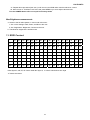
11. EDID Content
00
01
02
03
04
05
06
07
08
09
10
11
12
13
14
15
0:
00
FF
FF
FF
FF
FF
FF
00
10
AC
13
A0
30
39
37
38
16:
1C
0F
01
03
68
1E
17
78
2E
B0
60
A1
58
4F
95
26
32:
16
50
54
A5
4A
00
01
01
01
01
01
01
01
01
01
01
48:
01
01
01
01
01
01
64
19
00
40
41
00
26
30
18
88
64:
36
00
30
E4
10
00
00
18
00
00
00
FF
00
39
30
31
80:
32
33
34
35
36
38
37
39
30
0A
00
00
00
FD
00
38
96:
4C
1E
3F
08
00
0A
20
20
20
20
20
20
00
00
00
FC
112:
00
44
45
4C
4C
20
45
31
35
36
46
50
0A
20
00
0E
Note: Byte 0C, 0D, 0E, 0F means Serial No. Byte 10, 11 means manufacture time. Byte
7F means checksum
47
Dell E156FPc
12. ISP (In System Program) User Manual(take E153FP for example)
12.1 Connect ISP Writer preparation action
Connect RXD and TXD of PC to RXD (P3.0) and TXD (P3.1) of CPU through RS-232.
a. There are two ways to entering Reboot Mode. The settings for Reboot Mode is as follow
z
Both P2.6 P2.7 are LOW and RESET pin is HIGHT.
z
P4.3 is LOW and RESET pin is HIGHT.
48
Dell E156FPc
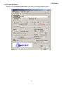
12.2 To Use ISP Writer
Press the “–“ key at front bezel and plug the AC power cord in, then the MCU enter ISP mode;
a. You will enter the window as follow after executing the ispwriter.exe file.
49
Dell E156FPc
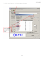
b. Click the “Select Chip” button, and choose the type you will program.
50
Dell E156FPc
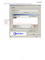
c. Click the “Select Bank0” button and selecting a file which a binary Format required.
51
Dell E156FPc
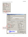
d. Select the communication Setting: Port Name
e. Click the “ConNect” button.
52
Dell E156FPc
f. Click “Program all” to start programming.
12.3. Executing ISP
a. “Program All” button that will execute erase and program and verify. Then you can get the window as
follow, and click “OK” to complete ISP process.
b. Complete the ISP process, click“exit LD”button to reset monitor.
53
Dell E156FPc
13.Check List
1) After replacing LCD Main board and panel, Check if white-balance is within the specs, then
re-writing DDC is necessary.
The white-balance value for each common color temperature:
9300 parameter is x=283±28, y=297±28, Y = 180 ±10 cd/m2,
6500 parameter is x =313±28, y=329±28, Y = 180 ±10 cd/m2,
5700 parameter is x = 328 ±28, y = 344 ±28, Y = 180 ±10 cd/m2)
The color temperature value above must be up to the situation of x<y. The value of Y should be confirmed
according to different customers. 15 ”LCD is commonly 180±20cd/cm2(Center)and 17” LCD is required to be
larger than 200cd/cm2 (Center). The exact brightness values are confirmed by the checking-regulations of
different customers and different models.
2) Steps of white-balance adjustment for LCD:(Take 17” AOC LCD LM724 for example)
1. Required instruments: Chroma7120、Chroma2325(BGA265A)
。
2. First connect the instruments together and turn on the LCD power, then warm up for 30 minutes under full
white screen mode. First press the “Reset” key in the menu to recover factory set as following.
Set Chroma2325 at round-windows mode and make the detecting-head of Chroma7120 aim at the
cross in the middle, the distance between the detecting-head and the cross is 20cm.
3. Set Chroma2325(BGA265A)to be T144(1280*1024/60HZ)and P105 of full white screen. Test if the
white-balance value is within the specs. Please follow the steps below to adjust if it is beyond the specs.
4. Cut the power. Then press MENU key and re-plug power cable at the same time to enter into the factory
mode. See the following pictures.
Select ”F",then Select
AUTO LEVEL item.
5. Test white-balance again after Auto Level. Adjustment with hand is necessary if it is beyond the specs.
6. Select 7x00 item to adjust cool color-temperature and select 6x00 to adjust warm color- temperature. It
can reach to the best effect through adjusting R/G/B value if it inclines to green or blue.
54
Dell E156FPc
7. Select Exit to the upper menu after completing the adjustment. Then press POWER OFF to exit and save
it.
3) Steps for writing DDC:
1. Employ PC, and connect the DDC-writing instrument and the instrument that is ready for writing into DDC to
the power of 12V. Connect the signal cable of the latter to D-USB or DVI of DDC-writing instrument (The
data-writing of monitor needs transfer-interface) and link the DDC-writing instrument with PC through printer
interface. (See the schematic picture below)
(Connection for VGA)
(Connection for DVI)
2. Seek the document with the expanded name of .BAT in DDC file of this model. It appears the indication of
“Input Serial No.:"after dual-click the document to be ready for DDC-writing.
3. Input the serial number of the product (For instance: AOC LM725 is 13 bits), and then press ENTER to start
writing
4.Check the indication of DDC-writing program at the end. When you see the picture as the schematic picture
above, the“Data compare OK!” Means being written well and that’s the end. Please check if the
Manufacturer Name, Vendor Assigned Code, Monitor Name, Serial Number, Week of Manufacture, Year of
Manufacture are right. It will appear “Data compare error! ” To indicate failure if the DDC-writing doesn’t
perform well. Please check the power resource and the connection of the signal cable, then return to step 3
by pressing ENTER and re-do it.
5.You can exit the program by pressing Ctrl plus C, and then cut the signal cable and the power.
6.The following picture is taking AOC LM725 EDID for example.
55
Dell E156FPc
Notes:
1. Make sure the system time of PC is in accordance with the real time before writing.
2. The schematic picture is just as an example for description; the exact content of the DDC is dependent on
the serial number of the BARCORD of this model.
3. Data DDC-writing needs a transfer interface.
Instruction:DDC-writing needs 4 files:
1. Barcode.txt
(Supply Barcode length and flow number)
2. *.EXE (DDC-writing program)
3.
WR.bat (Group order file for cycling utilization of *EXE, and dual-click this file when perform DDC-writing)
4. W.dat
(The content with 128 bits of DDC)
56
Dell E156FPc
14. BOM List
Part NO
Description
Quantity Unit
Remark
CBPC560KCDDLP
CONVERSION BOARD
1
PCS
For CPT panel
CBPC560KGDDLP
CONVERSION BOARD
1
PCS
For LPL panel
PWPC1521CPD2P
POWER BOARD
1
PCS
For CPT panel
PWPC1521LGD2P
POWER BOARD
1
PCS
For LPL panel
12G6105 1
PORON FOR PANEL
1
PCS
For LPL panel
12G6106 1
PORON FOR PANEL
1
PCS
For CPT panel
15G8183 1
MAIN FRAME-For CPT panel
1
PCS
For CPT panel
15G8183 2
MAIN FRAME-For LPL panel
1
PCS
For LPL panel
34G1606 Y2 1B
BACK COVER
1
PCS
For LPL panel
34G1606 Y2 2B
BACK COVER
1
PCS
For CPT panel
750GLC50P0162Z D
For CPT panel 15" ZBD PANEL
1
PCS
For CPT panel
750GLG50X08 4Z
LPL 15" TL01 ZBD PANEL
1
PCS
For LPL panel TL01
750GLG50X08 6Z
LPL 15" A5N1 ZBD PANEL
1
PCS For LPL panel A5N1
Location
Part NO
Description
Quantity
Unit
KEPC560KD9P
KEY BOARD
1
PCS
11G6080 1
SPACER SUPPORT
1
PCS
15G6261 1
BRACKET
3
PCS
15G8146 1
KEVSINGTON BRACKET
1
PCS
15G8185 1
HOLDER BRACKET R
1
PCS
15G8186 1
HOLDER BRACKET L
1
PCS
19G 588 1
SPRING HOLDER
2
PCS
19G 589 1
SPRING BUTTON
1
PCS
20G 027 1
STAND HOLDER
1
PCS
23G3178700 3A
logo
1
PCS
26G 800700 6A
S/N LABEL
1
PCS
33G4884ASN L
BUTTON FUNC
1
PCS
33G4885 Y2 L
BUTTON RELEASE
1
PCS
34G1605AY2 B
BEZEL
1
PCS
40G 15N700 1A
ID LABEL
1
PCS
40G 58162435A
LABEL
1
PCS
40G 581700 3A6813
CARTON LABEL
1
PCS
41G7800700 8A
E176 DAO PIG
1
PCS
41G7800700 9A
QSG
1
PCS
44G3586 1
EPS(L)
1
PCS
44G3586 2
EPS(R)
1
PCS
44G3586 3EPE
EPE
1
PCS
57
Dell E156FPc
44G3586700 1A
CARTON
1
PCS
44G3586BRO 1
PAPER BLOCK
1
PCS
44G3586BRO 2
PAPER BLOCK
1
PCS
45G 88606 8
PE BAG FOR BASE
1
PCS
45G 88607DE8
PE BAG
1
PCS
52G
SMALL TAPE
8
CM
52G6020 2DE8
PROTECT FILM
1
PCS
52G6022 1500
SMALL TAPE
12
CM
52G6025 11845
MYLAR FOR POWER BOARD
1
PCS
52G6025 11900
MYLAR FOR STAND HOLDER
2
PCS
52G6025 11905
MYLAR
1
PCS
52G6025 11924
MYLAR
1
PCS
70G1500700 5A
CD MANUAL
1
PCS
85G 701 1
SHIELD LAMP
1
PCS
85G 702 1
SHIELD WIRE
1
PCS
89G402A18NISD
POWER CORD
1
PCS
95G8018 20 11
LVDS HARNESS
1
PCS
M1G 130 4 47
SCREW
4
PCS
M1G 330 4128
SCREW M3X4
1
PCS
M1G1740 6128
SCREW
1
PCS
M1G2940 10225
SCREW
4
PCS
M1G3030 5125
SCREW
11
PCS
Q1G6019 1
SCREW
4
PCS
705G 780 87 D1
CN901 ASS'Y
1
PCS
705G560KB34124
LCD BACK COVER ASS'Y
1
PCS
89G 728LAA 2
SIGNAL CABLE
1
PCS
AIC560KCDDLP
MAIN BOARD
1
PCS
40G 457624 1B
LABEL-CPU
1
PCS
40G 45762412B
CBPC LABEL
1
PCS
C416
67G309V220 3
22UF +-20% 16V
1
PCS
C419
67G309V220 3
22UF +-20% 16V
1
PCS
C425
67G309V220 3
22UF +-20% 16V
1
PCS
C701
67G309V220 3
22UF +-20% 16V
1
PCS
C710
67G309V220 3
22UF +-20% 16V
1
PCS
C711
67G309V220 3
22UF +-20% 16V
1
PCS
C717
67G309V220 3
22UF +-20% 16V
1
PCS
CN101
33G8043 14 H
CONNECTER
1
PCS
CN403
33G8019 8C H
CONNEETER
1
PCS
CN405
88G 35315F H
D-SUB 15PIN
1
PCS
1186
58
Dell E156FPc
CN701
33G8027 12
WAFER 2*6P 2.0MM R/A
1
PCS
X401
93G 22 53
CRYSTAL 14.318MHzHC-49U
1
PCS
715G1565 1
MAIN BOARD
1
PCS
C102
65G0603104 12
CER2 0603 X7R 16V 100N
1
PCS
C402
65G0603104 12
CER2 0603 X7R 16V 100N
1
PCS
C403
65G0603104 12
CER2 0603 X7R 16V 100N
1
PCS
C404
65G0603104 12
CER2 0603 X7R 16V 100N
1
PCS
C405
65G0603104 12
CER2 0603 X7R 16V 100N
1
PCS
C406
65G0603104 12
CER2 0603 X7R 16V 100N
1
PCS
C407
65G0603104 12
CER2 0603 X7R 16V 100N
1
PCS
C410
65G0603104 12
CER2 0603 X7R 16V 100N
1
PCS
C411
65G0603104 12
CER2 0603 X7R 16V 100N
1
PCS
C412
65G0603104 12
CER2 0603 X7R 16V 100N
1
PCS
C413
65G0603104 12
CER2 0603 X7R 16V 100N
1
PCS
C414
65G0603104 12
CER2 0603 X7R 16V 100N
1
PCS
C417
65G0603104 12
CER2 0603 X7R 16V 100N
1
PCS
C418
65G0603104 12
CER2 0603 X7R 16V 100N
1
PCS
C420
65G0603104 12
CER2 0603 X7R 16V 100N
1
PCS
C421
65G0603104 12
CER2 0603 X7R 16V 100N
1
PCS
C422
65G0603104 12
CER2 0603 X7R 16V 100N
1
PCS
C423
65G0603104 12
CER2 0603 X7R 16V 100N
1
PCS
C424
65G0603104 12
CER2 0603 X7R 16V 100N
1
PCS
C426
65G0603104 12
CER2 0603 X7R 16V 100N
1
PCS
C427
65G0603330 31
CER1 0603 NP0 50V 33P P
1
PCS
C428
65G0603330 31
CER1 0603 NP0 50V 33P P
1
PCS
C430
65G0603104 12
CER2 0603 X7R 16V 100N
1
PCS
C431
65G0603104 12
CER2 0603 X7R 16V 100N
1
PCS
C432
65G0603473 32
CHIP 0.047UF 50V X7R
1
PCS
C433
65G0603473 32
CHIP 0.047UF 50V X7R
1
PCS
C434
65G0603473 32
CHIP 0.047UF 50V X7R
1
PCS
C435
65G0603224 17
CAP:CER 0.22UF-20%-80%
1
PCS
C436
65G0603473 32
CHIP 0.047UF 50V X7R
1
PCS
C437
65G0603473 32
CHIP 0.047UF 50V X7R
1
PCS
C438
65G0603473 32
CHIP 0.047UF 50V X7R
1
PCS
C439
65G0603104 12
CER2 0603 X7R 16V 100N
1
PCS
C441
65G0603104 12
CER2 0603 X7R 16V 100N
1
PCS
C442
65G0603220 31
CER1 0603 NP0 50V 22P P
1
PCS
C443
65G0603220 31
CER1 0603 NP0 50V 22P P
1
PCS
C444
65G0603104 12
CER2 0603 X7R 16V 100N
1
PCS
59
Dell E156FPc
C445
65G0603104 12
CER2 0603 X7R 16V 100N
1
PCS
C446
65G0603104 12
CER2 0603 X7R 16V 100N
1
PCS
C454
65G0603104 32
CHIP 0.1UF 50V X7R
1
PCS
C455
65G0603104 32
CHIP 0.1UF 50V X7R
1
PCS
C456
65G0603104 32
CHIP 0.1UF 50V X7R
1
PCS
C457
65G0603104 32
CHIP 0.1UF 50V X7R
1
PCS
C458
65G0603104 12
CER2 0603 X7R 16V 100N
1
PCS
C703
65G0603104 12
CER2 0603 X7R 16V 100N
1
PCS
C704
65G0603104 12
CER2 0603 X7R 16V 100N
1
PCS
C707
65G0603104 12
CER2 0603 X7R 16V 100N
1
PCS
C708
65G0603104 12
CER2 0603 X7R 16V 100N
1
PCS
C712
65G0603104 12
CER2 0603 X7R 16V 100N
1
PCS
C713
65G0603104 12
CER2 0603 X7R 16V 100N
1
PCS
C715
65G0603104 12
CER2 0603 X7R 16V 100N
1
PCS
C718
65G0603104 12
CER2 0603 X7R 16V 100N
1
PCS
D403
93G 6433P
BAV99
1
PCS
D404
93G 6433P
BAV99
1
PCS
D405
93G 6433P
BAV99
1
PCS
D406
93G 39146
LL5232B
1
PCS
D407
93G 64 42 P
BAV70 SOT-23
1
PCS
D408
93G 39146
LL5232B
1
PCS
D409
93G 39146
LL5232B
1
PCS
D410
93G 39146
LL5232B
1
PCS
D411
93G 39146
LL5232B
1
PCS
D412
93G 39146
LL5232B
1
PCS
D704
93G2004 2
SR24/PANJIT-SMT
1
PCS
FB401
71G 56K121 M
CHIP BEAD
1
PCS
FB402
71G 56K121 M
CHIP BEAD
1
PCS
FB403
71G 56K121 M
CHIP BEAD
1
PCS
FB404
71G 56K121 M
CHIP BEAD
1
PCS
FB405
71G 56K121 M
CHIP BEAD
1
PCS
FB406
71G 56K121 M
CHIP BEAD
1
PCS
FB410
71G 59C600
GP
CHIP BEAD 50 OHM 1608 F
1
PCS
FB411
71G 59C600
GP
CHIP BEAD 50 OHM 1608 F
1
PCS
FB412
71G 59C600
GP
CHIP BEAD 50 OHM 1608 F
1
PCS
FB702
71G 56K121 M
CHIP BEAD
1
PCS
Q401
57G 417 4
PMBS3904/PHILIPS-SMT(04
1
PCS
Q403
57G 417 4
PMBS3904/PHILIPS-SMT(04
1
PCS
Q703
57G 417 4
PMBS3904/PHILIPS-SMT(04
1
PCS
60
Dell E156FPc
Q704
57G 763 1A
AP2305N
1
PCS
Q706
57G 417 4
PMBS3904/PHILIPS-SMT(04
1
PCS
R101
61L0603472
RST SM 0603 RC0603 4K7
1
PCS
R402
61L0603249 0F
CHIP 249OHM 1/16W 1%
1
PCS
R406
61L0603472
RST SM 0603 RC0603 4K7
1
PCS
R407
61L0603472
RST SM 0603 RC0603 4K7
1
PCS
R408
61L0603472
RST SM 0603 RC0603 4K7
1
PCS
R409
61L0603101
RST SM 0603 RC0603 100R
1
PCS
R410
61L0603101
RST SM 0603 RC0603 100R
1
PCS
R411
61L0603101
RST SM 0603 RC0603 100R
1
PCS
R416
61L0603472
RST SM 0603 RC0603 4K7
1
PCS
R417
61L0603472
RST SM 0603 RC0603 4K7
1
PCS
R419
61L0603000
RST SM 0603 JUMP MAX 0R
1
PCS
R421
61L0603562
CHIP 5.6K OHM 1/10W
1
PCS
R422
61L0603103
RST SM 0603 RC0603 10K
1
PCS
R423
61L0603472
RST SM 0603 RC0603 4K7
1
PCS
R424
61L0603472
RST SM 0603 RC0603 4K7
1
PCS
R425
61L0603472
RST SM 0603 RC0603 4K7
1
PCS
R426
61L0603103
RST SM 0603 RC0603 10K
1
PCS
R427
61L0603472
RST SM 0603 RC0603 4K7
1
PCS
R429
61L0603103
RST SM 0603 RC0603 10K
1
PCS
R432
61L0603472
RST SM 0603 RC0603 4K7
1
PCS
R434
61L0603750
RST SM 0603 RC22H 75R P
1
PCS
R435
61L0603750
RST SM 0603 RC22H 75R P
1
PCS
R436
61L0603750
RST SM 0603 RC22H 75R P
1
PCS
R438
61L0603750 9F
75OHM 1% 1/10W
1
PCS
R439
61L0603750 9F
75OHM 1% 1/10W
1
PCS
R440
61L0603750 9F
75OHM 1% 1/10W
1
PCS
R441
61L0603101
RST SM 0603 RC0603 100R
1
PCS
R442
61L0603101
RST SM 0603 RC0603 100R
1
PCS
R443
61L0603101
RST SM 0603 RC0603 100R
1
PCS
R444
61L0603103
RST SM 0603 RC0603 10K
1
PCS
R445
61L0603221
RST SM 0603 RC0603 220R
1
PCS
R446
61L0603221
RST SM 0603 RC0603 220R
1
PCS
R447
61L0603221
RST SM 0603 RC0603 220R
1
PCS
R448
61L0603222
RST SM 0603 RC0603 2K2
1
PCS
R449
61L0603222
RST SM 0603 RC0603 2K2
1
PCS
R450
61L0603472
RST SM 0603 RC0603 4K7
1
PCS
R451
61L0603472
RST SM 0603 RC0603 4K7
1
PCS
61
Dell E156FPc
R452
61L0603472
RST SM 0603 RC0603 4K7
1
PCS
R453
61L0603221
RST SM 0603 RC0603 220R
1
PCS
R454
61L0603221
RST SM 0603 RC0603 220R
1
PCS
R455
61L0603221
RST SM 0603 RC0603 220R
1
PCS
R457
61L0603101
RST SM 0603 RC0603 100R
1
PCS
R458
61L0603101
RST SM 0603 RC0603 100R
1
PCS
R459
61L0603473
RST SM 0603 RC0603 47K
1
PCS
R460
61L0603473
RST SM 0603 RC0603 47K
1
PCS
R461
61L0603221
RST SM 0603 RC0603 220R
1
PCS
R462
61L0603221
RST SM 0603 RC0603 220R
1
PCS
R463
61L0603221
RST SM 0603 RC0603 220R
1
PCS
R464
61L0603221
RST SM 0603 RC0603 220R
1
PCS
R465
61L0603221
RST SM 0603 RC0603 220R
1
PCS
R466
61L0603103
RST SM 0603 RC0603 10K
1
PCS
R467
61L0603103
RST SM 0603 RC0603 10K
1
PCS
R468
61L0603103
RST SM 0603 RC0603 10K
1
PCS
R469
61L0603303
CHIP 30K OHM 5% 1/10W
1
PCS
R470
61L0603223
CHIPR 22K OHM +-5% 1/10
1
PCS
R471
61L0603223
CHIPR 22K OHM +-5% 1/10
1
PCS
R472
61L0603303
CHIP 30K OHM 5% 1/10W
1
PCS
R474
61L0603472
RST SM 0603 RC0603 4K7
1
PCS
R477
61L0603472
RST SM 0603 RC0603 4K7
1
PCS
R705
61L0603472
RST SM 0603 RC0603 4K7
1
PCS
R707
61L0603102
RST SM 0603 RC0603 1K P
1
PCS
R708
61L0603102
RST SM 0603 RC0603 1K P
1
PCS
R710
61L0603102
RST SM 0603 RC0603 1K P
1
PCS
R714
61L0603473
RST SM 0603 RC0603 47K
1
PCS
R722
61L0603000
RST SM 0603 JUMP MAX 0R
1
PCS
R723
61L0603473
RST SM 0603 RC0603 47K
1
PCS
R725
61L0603473
RST SM 0603 RC0603 47K
1
PCS
U401
56G 562101
GM2621-LF-BC
1
PCS
U402
56G1133 59CD1
SST25VF010-20-4C-SAE
1
PCS
U404
56G1133 34
M24C02-WMN6TP
1
PCS
U701
56G 563 7
AIC1084-33PM
1
PCS
U702
56G 563 27
AIC1117A-18CY SOT-223
1
PCS
AIK560KD9SMTP
KEY BOARD
1
PCS
715G1564 1
PCB
1
PCS
C01
65G0603104 12
CER2 0603 X7R 16V 100N
1
PCS
C02
65G0603104 12
CER2 0603 X7R 16V 100N
1
PCS
62
Dell E156FPc
CN1
89G176S 8 5
FFC CABLE
1
PCS
LED01
81G 14501 KT
CHIP LED
1
PCS
SW01
77G 605 1 AL GP
SMD SWITCH
1
PCS
SW02
77G 605 1 AL GP
SMD SWITCH
1
PCS
SW03
77G 605 1 AL GP
SMD SWITCH
1
PCS
SW04
77G 605 1 AL GP
SMD SWITCH
1
PCS
ZD01
93G 39S 34 T
UDZS5.6B
1
PCS
ZD02
93G 39S 34 T
UDZS5.6B
1
PCS
ZD03
93G 39S 34 T
UDZS5.6B
1
PCS
ZD04
93G 39S 34 T
UDZS5.6B
1
PCS
ZD05
93G 39S 34 T
UDZS5.6B
1
PCS
ZD06
93G 39S 34 T
UDZS5.6B
1
PCS
PW1521CPD2SMTP
POWER BOARD FOR SMT
1
PCS
40G 45762420A
ID LABEL
1
PCS
705G 560 57 D1
Q901 ASS'Y
1
PCS
705G 560 93 D1
D921 ASS'Y
1
PCS
BD901
93G 50460502
KBP206G
1
PCS
C203
67G215L471 4N
KY25VB470M-L10*16
1
PCS
C211
65L 3J2206ET
22PF 5% 3KV TDK
1
PCS
C212
65L 3J2206ET
22PF 5% 3KV TDK
1
PCS
C221
63G210J1842A2
PMS 0.18UF 250V
1
PCS
C900
65G306M4722BP
4700PF +-20% 400VAC
1
PCS
C901
65G305M2222BP
2200PF +-20%
1
PCS
C902
65G305M2222BP
2200PF +-20%
1
PCS
C903
63G 107474 HS
0.47UF +-20% 275VAC
1
PCS
C904
67G215S10115K
100UF 450V
1
PCS
C923
67G215L102 3R
LOW E.S.R 1000UF +/-20%
1
PCS
C924
67G215L102 3R
LOW E.S.R 1000UF +/-20%
1
PCS
C925
67G215L471 4N
KY25VB470M-L10*16
1
PCS
C926
67G215Y4713NV
KY16VB470M-CC3 8*15MM
1
PCS
CN201
33G8020 2D AC
CONN.2P R/A DIP BY ACES
1
PCS
CN202
33G8020 2D AC
CONN.2P R/A DIP BY ACES
1
PCS
CN901
33G8029 3A
3PIN (2PIN NC)
1
PCS
CN902
95G8014 12523
WIRE
1
PCS
D902
93G1020 752T
UF4003
1
PCS
D922
705G 780 57 08
D911 ASS'Y (ROHS)
1
PCS
IC902
56G 139 3A
PC123Y22FZOF
1
PCS
L201
73G 253515 L
CHOKE COIL
1
PCS
L901
73L 174 50 LH
LINE FILTER
1
PCS
63
Dell E156FPc
L902
73G 174 65 LS
LINE FILTER BY LISHIN
1
PCS
L903
73G 253 91 H
CHOKE COIL
1
PCS
L904
73G 253 91 H
CHOKE COIL
1
PCS
NR901
61G 58080 WT
8 OHM NCT
1
PCS
PT201
80GL15T 22 YS
X'FMR YSTDA200101G
1
PCS
Q203
57G 763 12
AOU401 BY AOS
1
PCS
Q206
57G 761 7
KTD1691P
1
PCS
Q207
57G 761 7
KTD1691P
1
PCS
R908
61G152M10458G6267
100K OHM 5% 2W
1
PCS
R918
61G152M398 64
0.39 OHM 2W
1
PCS
T901
80GL17T 29 LS
ADAPTOR BY LISHIN
1
PCS
PW1521CPD2AIP
POWER BOARD FOR AI
1
PCS
C201
65G0805104 22
0.1UF +-10% 25V X7R 080
1
PCS
C202
65G0805104 22
0.1UF +-10% 25V X7R 080
1
PCS
C204
65G0805104 22
0.1UF +-10% 25V X7R 080
1
PCS
C205
65G0805105 22 GP
CHIP 1UF 25V X7R 0805
1
PCS
C207
65G0805331 32
CHIP 330P 50V X7R 0805
1
PCS
C208
65G0805104 22
0.1UF +-10% 25V X7R 080
1
PCS
C210
65G0805105 22 GP
CHIP 1UF 25V X7R 0805
1
PCS
C222
65G0805474 22
CHIP 0.47UF 25V X7R 080
1
PCS
C223
65G0805105 22
CHIP 1UF 25V X7R 0805
1
PCS
C907
65G0805104 32
CHIP 0.1U 50V X7R
1
PCS
C911
65G0805471 31
CHIP 470PF 50V NPO
1
PCS
C912
65G0805102 32
CHIP 1000P 50VX7R 0805
1
PCS
C927
65G0805104 32
CHIP 0.1U 50V X7R
1
PCS
C928
65G0805104 32
CHIP 0.1U 50V X7R
1
PCS
C929
65G0805104 32
CHIP 0.1U 50V X7R
1
PCS
D201
93G3004 4
RB050L-40
1
PCS
D202
93G 6432P
LL4148
1
PCS
D203
93G 6432P
LL4148
1
PCS
D204
93G 6432P
LL4148
1
PCS
D205
93G 6432P
LL4148
1
PCS
D206
93G 6432P
LL4148
1
PCS
D903
93G 6432P
LL4148
1
PCS
F902
61L1206000
RST SM 1206 JUMP MAX 0R
1
PCS
IC201
56G 608 1
TL1451ACD
1
PCS
IC901
56G 379 54
NCP1203D60R2G BY ON
1
PCS
J918
61L0805000
CHIP O OHM 1/8W
1
PCS
J919
61L1206000
RST SM 1206 JUMP MAX 0R
1
PCS
64
Dell E156FPc
J920
61L1206000
RST SM 1206 JUMP MAX 0R
1
PCS
Q201
57G 760 5
DTC144WKA BY ROHM SMT
1
PCS
Q202
57G 760 4
DTA144WKA BY ROHM SMT
1
PCS
Q204
57G 417 4
PMBS3904/PHILIPS-SMT(04
1
PCS
Q205
57G 417 6
PMBS3906/PHILIPS-SMT(06
1
PCS
R201
61L0805240 1F
CHIPR 2.4KOHM +-1% 1/8W
1
PCS
R202
61L0805221
CHIPR 220 OHM +-5% 1/8W
1
PCS
R203
61L0805240 1F
CHIPR 2.4KOHM +-1% 1/8W
1
PCS
R204
61L0805471
CHIPR 470 OHM+-5% 1/8W
1
PCS
R205
61L0805183
18K&8 1/10W
1
PCS
R206
61L0805123
CHIP 12KOHM 1/8W
1
PCS
R207
61L0805103
CHIPR 10K OHM +-5% 1/8W
1
PCS
R208
61L0805000
CHIP O OHM 1/8W
1
PCS
R209
61L0805000
CHIP O OHM 1/8W
1
PCS
R210
61L0805683
CHIPR 68K OHM+-5% 1/8W
1
PCS
R212
61L0805473
CHIPR 47K OHM +-5% 1/8W
1
PCS
R213
61L0805472
CHIRP 4.7K OHM +-5% 1/8
1
PCS
R214
61L0805133
CHIPR 13KOHM +-5% 1/8W
1
PCS
R225
61L1206102
CHIP 1K OHM 5% 1/4W
1
PCS
R226
61L1206102
CHIP 1K OHM 5% 1/4W
1
PCS
R227
61L0805751
750 OHM
1
PCS
R228
61L0805561
CHIP 560 OHM 1/8W
1
PCS
R229
61L0805123
CHIP 12KOHM 1/8W
1
PCS
R230
61L0805510 2F
CHIP 51K OHM 1/10W
1
PCS
R900
61L1206334
330K 1/4W
1
PCS
R901
61L1206334
330K 1/4W
1
PCS
R902
61L1206334
330K 1/4W
1
PCS
R903
61L1206332
CHIP 3.3K OHM 5% 1/8W
1
PCS
R904
61L1206332
CHIP 3.3K OHM 5% 1/8W
1
PCS
R905
61L1206332
CHIP 3.3K OHM 5% 1/8W
1
PCS
R909
61L0805220
CHIP 22 OHM 5% 0805 1/8
1
PCS
R910
61L0805222
CHIP 2.2KOHM 5% 0805 1/
1
PCS
R911
61L0805362
CHIP 306KOHM 1/8W
1
PCS
R912
61L0805101
CHIPR 100 OHM +-5% 1/8W
1
PCS
R913
61L0805753
75K 1/8W
1
PCS
R914
61L0805472
CHIRP 4.7K OHM +-5% 1/8
1
PCS
R915
61L0805220
CHIP 22 OHM 5% 0805 1/8
1
PCS
R916
61L0805221
CHIPR 220 OHM +-5% 1/8W
1
PCS
R917
61L0805103
CHIPR 10K OHM +-5% 1/8W
1
PCS
65
Dell E156FPc
R919
61L0805203
CHIPR 20KOHM +-5% 1/8W
1
PCS
R924
61L0805102
CHIPR 1K OHM +-5% 1/8W
1
PCS
R925
61L0805000
CHIP O OHM 1/8W
1
PCS
R929
61L0805330 2F
CHIP 33KOHM 1/8W 1%
1
PCS
R930
61L0805360 1F
CHIP 3.6KOHM 1/8W 1%
1
PCS
R931
61L0805102
CHIPR 1K OHM +-5% 1/8W
1
PCS
R932
61L0805102
CHIPR 1K OHM +-5% 1/8W
1
PCS
R933
61L0805240 1F
CHIPR 2.4KOHM +-1% 1/8W
1
PCS
ZD201
93G 39S 8 T
RLZ11B LLDS
1
PCS
ZD901
93G 39S 44 T
RLZ18B LLDS
1
PCS
ZD902
93G 39S 25 T
RLZ5.1B LLDS
1
PCS
ZD903
93G 39S 38 T
PTZ 9.1B
1
PCS
ZD904
93G 39S 40 T
RLZ 13B LLDS
1
PCS
ZD905
93G 39S 25 T
RLZ5.1B LLDS
1
PCS
715G1563 1
PCB
1
PCS
C209
67G 305330 7T
33UF 105 1
PCS
C904
6G 31502
1.5MM RIVET
2
PCS
C905
65G 2K152 1T6921
1.5NF/2KV Y5P +-10%
1
PCS
C906
67G 2151014KT
100UF
1
PCS
C909
67G 3054704KT
47UF
1
PCS
C921
65G517K102 5T
1000PF 10% Y5P 500V
1
PCS
C922
65G517K102 5T
1000PF 10% Y5P 500V
1
PCS
CN901
6G 31500
EYELET
2
PCS
D901
93G 6026W52T
FR107
1
PCS
F901
84G 56 1
FUSE 2A 250V WICKMANN
1
PCS
FB201
71G 55 19 T
FERRITE BEAD D9X3. 5X0.
1
PCS
IC903
56G 158 12
KIA431A-AT/P TO-92
1
PCS
L902
6G 31502
1.5MM RIVET
4
PCS
Q902
57G 420 PP T
2PA733P
1
PCS
Q903
57G 419 PP T
2PC945P
1
PCS
R221
61G 17224252T
2.4KOHM 5% 1/4W
1
PCS
R222
61G 17224252T
2.4KOHM 5% 1/4W
1
PCS
R223
61G 17224252T
2.4KOHM 5% 1/4W
1
PCS
R224
61G 17224252T
2.4KOHM 5% 1/4W
1
PCS
R921
61G175L47052T
47OHM +-5% 1/2W
1
PCS
R922
61G175L47052T
47OHM +-5% 1/2W
1
PCS
R923
61G 17256152T
560 OHM 5% 1/4W
1
PCS
T901
6G 31502
1.5MM RIVET
4
PCS
HEAT SINK
1
PCS
90G6084 1
GP
66
Dell E156FPc
Q901
M1G1730 8128
SCREW M3x8
1
PCS
57G 600 35
STP8NK80ZFP
1
PCS
HEAT SINK
1
PCS
M1G1730 8128
SCREW M3x8
1
PCS
93G 60239
FME-210B T0-220
1
PCS
90G 410 2
HEAT SINK
1
PCS
87G 501 14 RF
AC SOCKET
1
PCS
95G 900595
WIRE
1
PCS
95G8021 3 11
HARNESS
1
PCS
96G 29 6
SHRINK TUBE UL/CSA
3
PCS
12G6097 1
PORON
6
PCS
15G8184 1
BASE BKT
1
PCS
15G8190 1
VESA-PLATE
1
PCS
20G 029 1
STAND DIE CAST
1
PCS
34G1607 Y2 B
VESA COVER
1
PCS
34G1608 SN B
RISER FRONT
1
PCS
34G1609 Y2 B
RISER REAR
1
PCS
34G1610ASF B
BASE
1
PCS
37G 535 1
HINGE ASS'Y(15")
1
PCS
M1G 130 6125
SCREW
4
PCS
M1G 130 8120
SCREW
3
PCS
M1G 140 8225
SCREW M3X8
2
PCS
Q1G 130 8 47
SCREW
4
PCS
90G6084 1
D921
GP
67
Dell E156FPc
15. Definition of Pixel Defects
15.1CLAA150XP01
68
Dell E156FPc
15.2 LM150X08
15.2.1 Dot Defect
15.2.1.1 Bright Dot
Dots(sub-pixels) which appeared brightly in the screen when the LCM displayed with dark pattern.
- R, G or B 1 dot --------------------------------- 0 Max
- Adjacent 2 dots -------------------------------- 0 Max
- Total amount of Bright dots -------------------- 0 Max
- Minimum distance of Bright dots --------------- NA
15.2.1.2. Dark Dot
Dots(sub-pixels) which appeared darkly in the screen when the LCM displayed with bright pattern.
- 1 dot -------------------------------------------- 4 Max
- Adjacent 2 dots -------------------------------- 1 Max
69
Dell E156FPc
- Total amount of Dark dot ---------------------- 4 Max
- Minimum distance of Dark dots --------------- 15mm
15.2.1.3. Total amount of Dot Defects -------------------- 4 Max (Combination)
Note) a. Every dot herein means Sub-Pixel (Each Red, Green, or Blue Color)
b. Bright dot
- Red or Blue dots smaller than half size of sub-pixel are not counted as a defect dots.
- Green dots smaller than 1 / 3 size of sub-pixel are not counted as a defect dots.
c. Dark dots smaller than half size of sub-pixel are not counted as a defect dots
15.2.2 Polarizer Defects
Where, W: Width
L: Length
D: Average diameter =(a+b)/2
a. Extraneous substances which can be wiped out, like Finger Print, Particles, are not considered as a defect.
b. Defects which is on the Black Matrix(outside of Active Area) are not considered as a defect.
15.2.3 Foreign Material
Where, W: Width
L: Length
D: Average diameter =(a+b)/2
15.2.4. Line Defect
All kinds of line defects such as vertical, horizontal or cross are not allowed.
15.2.5. Bezel Appearance
Scratches, minor bents, stains, particles on the Bezel frame are not considered as a defect.
15.2.6. Others
Issues which are not defined in this criteria shall be discussed with both parties, Customer and Supplier, for
better solution.
70