1
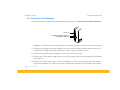
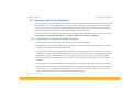
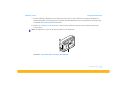
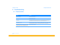
intelligent reliable power Enecsys Micro-Inverters Installation Guide Version 1.0 Installation Manual Intelligent Reliable Power CONTENTS Introduction Conventions used in this manual Safety Pre-Installation Checks Major components Installation overview Mounting the Enecsys Micro-inverters and cabling harness Installing the AC mains cabling and Gateway Test, inspect and connect the DC link cables Connecting the DC link cabling Connect the AC cabling Performing commmunication checks Creating a roof layout Creating an installation owner account Mounting Enecsys Micro-inverters Installing and connecting the AC Bus cabling Connecting the DC cable link harnesses Connecting the Gateway to the home network 1 1 2 5 7 8 8 8 8 8 9 9 10 10 11 13 15 17 © ENECSYS 2010. All rights reserved. i Installation Manual Power on the Gateway Repeater and Double Repeater Install either a Repeater or Double Repeater Commissioning the system Final steps Troubleshooting Communication Monitoring Conformity Gateway Repeater Double Repeater Antenna Micro-inverter Printing Notes © ENECSYS 2010. All rights reserved. ii Intelligent Reliable Power 18 20 20 22 23 24 24 25 26 26 27 28 29 29 30 31 Installation manual Intelligent Reliable Power 1. Introduction This manual is intended for installers and electricians involved in the installation and set up of Enecsys Solar Micro-inverter systems. It is expected that installers will have knowledge of the necessary steps needed for safe and successful installation of Enecsys Micro-inverters and associated apparatus. Electricians will have knowledge of their specific country electrical codes and regulations as well as safe methods of practice. 1.1 Conventions used in this manual This is a note, it brings to your attention some thing which you may be interested to know. This is a note, it brings to your attention some thing which you may be interested to know. The following conventions are used throughout this manual, these conventions should be noted and followed at all times. Warning: Warning statements must be heeded at all times. A warning symbol indicates that a process or instrument has the potential to harm or cause lethal injury if the correct method of handling is not employed. Caution: Caution statements are used to indicate where a part of the installation process may have the potential to damage equipment. Caution statements should be followed at all times. Attention: Attention statements are used to indicate where a part of the process or instrument has a special requirement. Attention statements should be followed at all times. Note: Notes are information that may be of use to the installer whilst performing an installation. © ENECSYS 2010. All rights reserved. 1 Installation manual Intelligent Reliable Power 1.2 Safety Before installing and using any Enecsys Micro-inverter please ensure that you have fully read and understand all of the installation instructions and heed all warnings and cautions given. • Warning: The installation and/or replacement of Enecsys Micro-inverters must only be carried out by qualified professionals. • Warning: All electrical installations should be performed in accordance with all local and national electrical installation codes and practice. • Caution: The Aluminium body of the Enecsys Micro-inverter serves as the heat-sink for the unit and as such can reach temperatures of 70⁰C. The Enecsys Micro-inverter should not be touched whilst in operation. • Warning: Lightning protection To avoid voltages being induced by lightning, the roof-mounted wiring should be arranged as radial branches, or as a single branch. Wiring loops or rings should not be used. Further independent active protection against lightning strike may be required, to local and national standards. • Warning: Isolation of the AC cabling The AC wiring from the inverters must have provision for electrical isolation from the grid mains supply, so that inspection, fault detection, testing, maintenance and repair can be performed. • Warning: Never disconnect any Photovoltaic module from an Enecsys Micro-inverter without first isolating the AC mains. © ENECSYS 2010. All rights reserved. 2 Installation manual Intelligent Reliable Power • Attention: Protection on the AC wiring Further protection on the AC wiring from the inverters should be provided and may be required by local and national wiring Regulations. This protection is likely to include Residual Current Devices, Earth Fault Monitors and Circuit breakers. • Attention: Voltage drop across the wiring To ensure that the system is operating efficiently, the voltage drop across the wiring should be verified. This is best done by direct measurement of the circuit impedances, but could be arrived at by calculations, graphs or tables. • Attention: Installation Testing Initial verification, before being connected to the grid mains supply, the wiring installation must be inspected and tested to verify that the requirements of the regulations have been met. The type and level of the tests must be in accordance with the local and national regulations. The tests and the interpretation of the results must be carried out by suitably qualified persons. • Attention: Enecsys Micro-inverters contain no user-serviceable parts, do not attempt to open or repair. Opening or tampering with the Enecsys Micro-inverter will void the warranty. If your Micro-inverter(s) fail(s) contact your installer company or the Enecsys help desk. • Warning: The inverter and metalwork must be earthed in accordance with national and local electrical standards. • Attention: The Gateway and Repeater/Double Repeater are intended for stationary in-door use only. © ENECSYS 2010. All rights reserved. 3 Installation manual Intelligent Reliable Power - Do not mount in a location where they will be exposed to direct/excessive solar and/or heat radiation. - Do not expose to heat-trap conditions or to water condensation. - Do not use liquid or aerosol cleaners when cleaning, clean only with a damp cloth. - Do not use near water. Transition of these items from a cold to a hot environment may cause condensation on some of the internal parts. If you notice condensation on or behind the lens of the product allow it to dry naturally before re-connecting to the main electrical supply. • Warning: If either the Gateway or the Repeater/Double Repeater exhibit any of the following characteristics unplug the products from the mains electrical supply. Contact either your distributor or installation company. - The power supply or its plug are damaged. - If liquid has been spilled into the product. - The product has been exposed to rain or water. - If the product does not operate properly. - If the product has been dropped or damaged in any way. - If there are noticeable signs of overheating. © ENECSYS 2010. All rights reserved. 4 Installation manual Intelligent Reliable Power 1.3 Pre-Installation Checks Before commencing the physical installation of the Micro-inverters installers should ensure that following pre-installation checks have been completed. 1. The installation company has contacted the Enecsys agent and requested an on-line installer user account, that the installer user account has been created and that the installer is in possesion of the following information: • The Enecsys monitoring site URL. This is a note, it brings to your attention some thing which you may be interested to know. This is a note, it brings to your attention some thing which you may be interested to know. • A valid monitoring site username and password. Note: Creating an installer user account needs to be perfomed only once. 2. That the Enecsys checklist has been used by the installation company to survey the prospective customer for suitability of the Enecsys instalation. The checklist amongst other information ascertains the following information: • Type of roof material where the installation will take place. • That the installation premises have a broadband connection. • That the premises router has an available Ethernet socket. • That there are sufficient AC mains power supply sockets available near the premises router for the Gateway and within the roof space for a Repeater should one be needed. © ENECSYS 2010. All rights reserved. 5 Installation manual Intelligent Reliable Power 3. The customer has been presented with and signed the data protection act consent form, and that the data protection act consent form has been faxed to the Enecsys agent. 4. The the installer company has created a logcal installation using the Enecsys installation tool and created an installation on the system. 5. The installation map has been given to the installers, the installation map contains information regarding the following: • Inverter placement and serial numbers. • Specific mounting instructions. • Parts list and collection. © ENECSYS 2010. All rights reserved. 6 Installation manual Intelligent Reliable Power 1.4 Major components The following illustration details the major components associated with an Enecsys solar installation. Installers should ensure that they have all the necessary parts prior to commencing the solar installation. o. t N ate ge Parld D o. lta Bui l N t Voltage .com Seria. Inpu Vo ltage ys nt PP cs Max. M P Vourre ne 40 P ge Min . M t C w.e MI-2 pu lta Max. In re t Vo . ww S eq Maxlosu utput Fr nt re O Enced utpu Cur ture O t ra at R ed pu pe ut Rat . O t Tem Maxbien lass C Amety Saf MICRO-INVERTER X-X X-X X-X-S X-X -D I-X WW xx xx YY- xx xx xx V 48 V 29 V 42 8A 66 IP 0V 24 z H C 50 5° 1.2AC +6 0° -4 1 GATEWAY REPEATER / DOUBLE REPEATER FIGURE 1. The Micro-inverter, Gateway device and Repeater/Double Repeater. © ENECSYS 2010. All rights reserved. 7 Installation manual Intelligent Reliable Power 2. Installation overview There are five major steps needed to complete the installation of the Enecsys Micro-inverter Solar installation, a brief description outlining each part of the process is detailed below. 2.1 Mounting the Enecsys Micro-inverters and cabling harness This is a note, it brings to your attention some thing which you may be interested to know. This is a note, it brings to your attention some thing which you may be interested to know. In this part of the installation process the installer, following the installation map, mounts all of the inverters on the racking/mounting system, prepares the roof penetration conduit and fits/ lays the AC branch bus cabling. Note: It is important that the location and the serial numbers of the Micro-inverters are recorded. 2.2 Installing the AC mains cabling and Gateway In tandem with the roof installation phase, the installer fits the Gateway device (near to the consumer internet router) and prepares the AC drop cabling, ready for connection to the mains utility grid. 2.3 Test, inspect and connect the DC link cables When all of the AC cabling is finally in place, but before it is connected to the grid, it must be inspected and tested to verify compliance with the relevant electrical installation standards. 2.3.1 Connecting the DC link cabling Connect the DC link cabling harness from the PV modules to the inverters. © ENECSYS 2010. All rights reserved. 8 Installation manual Intelligent Reliable Power 2.3.2 Connect the AC cabling Connect the AC cable to the mains utility grid, via the appropriate protection devices. 2.4 Performing commmunication checks At this point the installer ensures that there are sufficient, stable communication links between the inverters and Gateway and that all inverters are in communication with the Gateway. If there is an insufficient level of stable communication, depending on the requirement, a Repeater or Double Repeater is installed. This is a note, it brings to your attention some thing which you may be interested to know. This is a note, it brings to your attention some thing which you may be interested to know. Note: this completes the physical installation process. © ENECSYS 2010. All rights reserved. 9 Installation manual Intelligent Reliable Power 3. Creating a roof layout An installation map details the amount and position/placement of Photovoltaic modules and Micro-inverters used in any one installation. On an roof layout plan the serial number of each Micro-inverter is recorded against its placement on the mounting surface. Once an installation map has been created and agreed with the customer it can then be given to the engineers who will use the plan to construct the installation. For full instructions on creating an installation map please refer to the Enecsys System Monitoring Manual. 4. Creating an installation owner account For full instructions on creating an installation owner account please refer to the Enecsys System Monitoring Manual. © ENECSYS 2010. All rights reserved. 10 Installation manual Intelligent Reliable Power 5. Mounting Enecsys Micro-inverters Attention: Ensure that there is a gap of at least one cm. (10mm) between the Micro-inverter and the back of the PV module. Attention: Ensure that there is a gap of at least one cm. (10mm) between the Micro-inverter and the roof surface. Attention: Ensure that there is sufficient space to mount the Micro-inverter. see Figure 3 for inverter dimensions. 10 mm min 10 mm min FIGURE 2. Micro-inverter placement showing a 10mm gap between the mounting surface and PV module. Lay-out all of the Enecsys Micro-inverters next to their corresponding positions as indicated by the installation map, matching the serial numbers on the inverters with those shown on the map. Depending on the PV mounting type used, mount the Micro-inverters using the most appropriate mounting method. © ENECSYS 2010. All rights reserved. 11 Installation manual Intelligent Reliable Power Attention: Always mount the inverter with the white disc (antenna cover) facing downwards, pointing away from the back of the module. 244.5 5.5 Typ 76.7 38.4 AC CABLE 5 Typ Serial No. Max. Input Voltage Min. MPP Voltage Max. MPP Voltage Max. Input Current Enclosure Rated Output Voltage Rated Output Freq. Max. Output Current Ambient Temperature Safety Class I-XX-XX-XX-XX-X YY-WW-D-S xxxxxxxxxx 48V 29V 42V 8A IP66 240V 50Hz 1.2A -40°C +65°C 1 179.5 www.enecsys.com Part No. Build Date SMI-240 -Ve DC +Ve DC ANTENNA COVER D DETAIL D FIGURE 3. Inverter dimensions. © ENECSYS 2010. All rights reserved. 12 EARTH CLAMP Installation manual Intelligent Reliable Power 5.1 Installing and connecting the AC Bus cabling Caution: Attention: Ensure that a waterproof end-cap is used to seal any unused connection points remaining open on the last AC distribution connection box. Warning: Attention: Dependant on the model used, the maximum number of Micro-inverters in any AC branch circuit must not exceed the maximum allowed. AC CONNECTION FROM MICRO-INVERTER AC BUS EXTENSION DISTRIBUTION CONNECTOR AC CONNECTION FROM MICRO-INVERTER END CAP FIGURE 4. Typical AC bus connection. Any number of radial branches, up to the maximum number of inverters allowed. Each inverter has one AC branching cable with pre-attached connector. This AC branching cable has a nominal length of 900 mm and is terminated with a three pin connector. © ENECSYS 2010. All rights reserved. 13 Installation manual Intelligent Reliable Power The AC branching cable is attached to distribution connection box. All of the AC connectors are linked through AC distribution connection blocks to form one continuous AC branch circuit. Each AC distribution connector block is capable of hosting three AC branch connectors and there respective Micro-inverters plus one AC Bus Extension cable 1. Using one distribution connector block for every two Micro-inverters connect one AC Bus Extension connection cable between each of the distribution connector blocks in sequence. 2. Connect the AC lead from each Micro-inverter to the AC distribution connector of the following inverter to form the AC branch circuit and so on, until all of the Micro-inverters are connected. 3. Always use an end cap to securely seal any open socket points on the distribution connector. There must not be any exposed AC socket points as these AC points will be live when the system is connected to the utility grid, except when specifically isolated. © ENECSYS 2010. All rights reserved. 14 Installation manual Intelligent Reliable Power 5.2 Connecting the DC cable link harnesses Warning: The AC bus cable must be isolated from the mains utility before attempting any repairs or maintenance. Warning: Never disconnect the DC cabling whilst under load. Attention: Once the Photovoltaic modules are exposed to daylight they will start to produce a DC current. PV MODULE JUNCTION BOX MICRO-INVERTER DC LINK CABLES AC CONNECTOR FIGURE 5. Connecting the DC link cables from the Micro-inverter to the junction box of the PV module. © ENECSYS 2010. All rights reserved. 15 Installation manual This is a note, it brings to your attention some thing which you may be interested to know. This is a note, it brings to your attention some thing which you may be interested to know. Intelligent Reliable Power Notes: • Once the Photovoltaic modules are exposed to daylight and connected to the Enecsys Microinverters, the inverters will start communicating with the Gateway. • Energy production will only commence once the AC cabling is connected to the AC utility grid. • Each Micro-inverter has two DC link cables, one male and one female. The DC harness link cables are terminated with single pole connectors of various types, depending on the installation and have a nominal length of 150 mm. The connectors used on all Enecsys Micro-inverters are compliant with all major PV module manufacturers DC link connectors. These connection types are as follows: • Multi-Contact MC3. • Multi-Contact MC4. • Huber & Suhner Radox. • Tyco Solarlok System. Connect the DC cable link harness from the Micro-inverters to the DC cabling from PV module's junction box. Depending on the type of connector present ensure that all snap closures are secure and that push connectors are twist locked. © ENECSYS 2010. All rights reserved. 16 Installation manual Intelligent Reliable Power 5.3 Connecting the Gateway to the home network 1. Connect the supplied Ethernet/LAN cable to a spare Ethernet/LAN port on the rear of the home router. 2. Connect the remaining end of the supplied Ethernet cable to the Ethernet port on the left hand side of the Enecsys Gateway as shown in Figure 6. By default the first screen presented is the ‘home user screen’. For full instructions on connecting the Gateway to the home network please refer to the Gateway Installation Manual. GATEWAY ETHERNET CABLE ROUTER FIGURE 6. Connect the Gateway to the home network. © ENECSYS 2010. All rights reserved. 17 Installation manual Intelligent Reliable Power 5.4 Power on the Gateway For full instructions on installing the Gateway please refer to the Gateway Installation Manual. 5V DC IN INSTALLER MODE SWITCH ETHERNET CABLE IN FIGURE 7. The Gateway device showing 5V DC in socket, Ethernet cable socket and installer mode switch. 1. If necessary configure the power adaptor for the national socket standard then connect the supplied 5V DC plug top power adapter to a mains supply AC power source. 2. Connect the supplied power adapter to the mains electrical supply. 3. Connect the 5V DC power supply jack to the 5V DC power input on the Gateway, the Gateway will power on. 4. Observe the 'home user screen', which, by default, is the first screen presented upon powering up the Gateway. The ‘home user screen’ graphically indicates to the installer the number © ENECSYS 2010. All rights reserved. 18 Installation manual Intelligent Reliable Power of Micro-inverters in direct communication with the Gateway. The number presented on the screen should match the number of inverters used as part of the installation. 5. Switch the Gateway into installer mode from the ‘home user’ screen by inserting a pointed object into the installer mode slot for approximately five seconds. 6. Check the strength of the communication link between the Micro-inverters and the Gateway. One of the following 3 symbols will be displayed: Symbol Description Action X Very weak communication link Add a Repeater. ? Marginal communication link Add a Repeater. Good Communication link This symbol displayed to assure a reliable communication. Table 1: Gateway status icons. 7. Having established that the communication link between the Micro-inverter/s and the Gateway is sufficient, proceed to the 'commissioning phase' of the installation process. 8. If an insufficient communication link is presented, a Repeater or Double-Repeater may need to be installed, proceed to “Repeater and Double Repeater”. © ENECSYS 2010. All rights reserved. 19 Installation manual Intelligent Reliable Power 5.5 Repeater and Double Repeater Enecsys Repeaters are employed to improve the communication link between the inverters and the Gateway. The Enecsys Repeater is a 'plug and play' device; it is quickly and easily installed. The Enecsys Repeater should be installed within the roof-space of the building and positioned within easy connection distance of a mains supply AC power source. For full instructions on how to correctly install a Repeater/Double-Repeater please refer to either the Repeater Installation Manual or the Double-Repeater Installation Manual. 5.5.1 Install either a Repeater or Double Repeater 1. Select the appropriate location for mounting the Enecsys Repeater. 2. Attach the antenna to the SMA plug on the right hand side of the Enecsys Repeater, screw the antenna into place in a clockwise direction. 3. Connect the 5V DC power supply jack-plug to the DC power port on the reverse of the Enecsys Repeater, thread the cable through the semi-circular channel on the back-plate of the Enecsys Repeater, this will help to keep the cable in place and prevent it from becoming detached. 4. To turn the Enecsys Repeater on connect the supplied 5V DC power supply to the AC mains supply. 5. The Repeater or Double Repeater should appear on the Gateway screen within five minutes. 6. Check the communication link to establish that the signal strength meets the requirement of the service. A symbol must be presented on the screen of the Gateway, this symbol indicates that a sufficient communication has been established. © ENECSYS 2010. All rights reserved. 20 Installation manual Intelligent Reliable Power 7. If, after adding a Repeater, the communication link is still insufficient another Repeater or Double Repeater will need to be installed. Double Repeaters use a combination of externally mounted and internally fixed antennas. This is a note, it brings to your attention some thing which you may be interested to know. This is a note, it brings to your attention some thing which you may be interested to know. 8. Return to “Power on the Gateway” within the installation process and repeat the process from step 4. Note: A Repeater is seen as an extra node on the Gateway. FIGURE 8. Connecting and powering on the Repeater. © ENECSYS 2010. All rights reserved. 21 Installation manual Intelligent Reliable Power 5.6 Commissioning the system Warning: Connection of the AC bus extension to the Mains Utility Grid must only be performed by a qualified electrician. Under no circumstances should anyone other than a qualified electrician attempt to connect the AC Bus extension to the utility mains grid. Failure to heed this warning may result in electrical shock and death. Attention: It is the responsibility of the installer/electrician to install all relevant apparatus and to grid connect the solar photovoltaic installation in accordance with the regional/national electrical codes regulations of installation country. Attention: It is the responsibility of the qualified electrician to perform all relevant safety checks before fully commissioning the solar photovoltaic installation. 1. The electrician switches on the system, the system is now feeding renewable energy into the utility grid, generating a return on investment. © ENECSYS 2010. All rights reserved. 22 Installation manual Intelligent Reliable Power 5.7 Final steps Check that the position of the Micro-inverters and that their serial numbers match the Microinverter/serial number positions on the installation map, make any changes to the installation map that are needed. 1. The installer Logs onto the Enecsys Monitoring System, navigates to the current pending installation and edits the online installation map to amend layout/serial number if necessary. 2. On the pending installation screen of the monitoring service ensure that all columns are checked with a before moving on to the next step. If any columns checked with an X remain the installer will not be able to fully confirm the installation as ‘Live’. 3. From the pending installation screen, Click ‘Go Live’. The installation is now live on the server. 4. Call your Enecsys agent and confirm that installation is now live. The Enecsys Agent creates the installation owner’s user account and checks the the user’s monitoring site. 5. The Enecsys agent gives the installer the installation owners account details. 6. Check, by confirming with the Enecsys Monitoring System, that all Micro-inverters are functioning correctly. This is a note, it brings to your attention some thing which you may be interested to know. This is a note, it brings to your attention some thing which you may be interested to know. 7. The installation company passes on all of the ‘Home User's’ account details to the installation owner. Note: The End User monitoring account details can only be given to the installation company once Enecsys have been provided with the signed Data Protection consent form, signed by the End User. © ENECSYS 2010. All rights reserved. 23 Installation manual Intelligent Reliable Power 6. Troubleshooting 6.1 Communication Problem Solution No illuminated display presented when the Gateway device is powered on. Ensure the power supply is plugged in and powered on. Replace the Gateway device. The Gateway device does not connect to the internet. Check the Ethernet cable and router. Replace the Gateway device. The Gateway device shows 0 when the Micro-inverters are installed. Check the Gateway installation manual: Have the Micro inverters been installed correctly i.e. communication disk is facing downwards. Is the installation on a metallic roof, if yes, have you installed a Double Repeater? The Gateway device is not showing the correct number of installed Micro-inverters. Check Module/Micro-Inverter connection. Is there sufficient sunlight on the modules? (During night the Gateway will always show 0 unless a Repeater or Double Repeater has been installed, in which case the Gateway device will show 1 or as many repeaters as there are in the installation). The sad smiley symbol on the Gateway device is visible, however, the correct number of installed Micro-inverters is displayed as well as the communication tick symbol. Check the internet connection. Table 2: Communication troubleshooting. © ENECSYS 2010. All rights reserved. 24 Installation manual Intelligent Reliable Power 6.2 Monitoring Problem Solution The installation does not appear as ‘live’ after being set to ‘live’ on the monitoring site. Check that all tabs on the monitoring site have been filled in corrrectly and that no ‘red crosses’ are present. All of the Micro-inverters show 0W power . Check the visual number on the Gateway Device to make sure all the Micro-inverters are communicating. Check that the system is properly connected to the utility grid. Check you have grid voltage from the AC cable on the roof. One or only few Inverters showing 0W power Check the visual number on the Gateway device to make sure inverters are communicating. Cannot Log-In After installation set live by installer and user account created. Call the Enecsys Support Function. Excessive time elapses when downloading monitoring data. Click the tab again or refresh the page. Table 3: Monitoring troubleshooting. © ENECSYS 2010. All rights reserved. 25 Installation manual Intelligent Reliable Power 7. Conformity Enecsys Micro-inverters and their associated apparatus conform to the following standards. 7.1 Gateway IC: 9052A-GATEWA01 Operation is subject to the following two conditions: (1) this device may not cause harmful interference, and (2) this device must accept any interference, including interference that may cause undesired operation of the device. Electrical Product Safety IEC 60950-1:2005 (2nd Edition); Am 1:2009; Compliance with National Differences :IEC60950_1B attachment EN60950-1:2006/A11:2009/ A1:2010 EMC EN 301 489-17 V2.1.1 - ElectroMagnetic compatibility and Radio spectrum Matters (ERM); ElectroMagnetic Compatibility (EMC) standard for radio equipment and services; Part 1: Common Technical Requirements. Spectrum EN 300 328 V1.7.1 - (Radio Module) Electromagnetic Compatibility and Radio Spectrum Matters (ERM) Wideband transmission systems; Data transmission equipment operating in the 2.4GHz © ENECSYS 2010. All rights reserved. 26 Installation manual Intelligent Reliable Power ISM band and using wideband modulation techniques; Harmonised EN covering essential requirements under article 3.2 of the R&TTE Directive. 7.2 Repeater IC: 9052A-REPEAT01 Operation is subject to the following two conditions: (1) this device may not cause harmful interference, and (2) this device must accept any interference, including interference that may cause undesired operation of the device. Electrical Product Safety IEC 60950-1:2005 (2nd Edition); Am 1:2009; Compliance with National Differences :IEC60950_1B attachment EN60950-1:2006/A11:2009/ A1:2010 EMC EN 301 489-17 V2.1.1 - ElectroMagnetic compatibility and Radio spectrum Matters (ERM); ElectroMagnetic Compatibility (EMC) standard for radio equipment and services; Part 1: Common Technical Requirements. Spectrum EN 300 328 V1.7.1 - (Radio Module) Electromagnetic Compatibility and Radio Spectrum Matters (ERM) Wideband transmission systems; Data transmission equipment operating in the 2.4GHz ISM band and using wideband modulation techniques; Harmonised EN covering essential requirements under article 3.2 of the R&TTE Directive. © ENECSYS 2010. All rights reserved. 27 Installation manual Intelligent Reliable Power 7.3 Double Repeater IC: 9052A-DEREP01 FCC. YIWDEREPEATER0001 Operation is subject to the following two conditions: (1) this device may not cause harmful interference, and (2) this device must accept any interference, including interference that may cause undesired operation of the device. Electrical Product Safety IEC 60950-1:2005 (2nd Edition); Am 1:2009; Compliance with National Differences :IEC60950_1B attachment EN60950-1:2006/A11:2009/ A1:2010 EMC EN 301 489-17 V2.1.1 - ElectroMagnetic compatibility and Radio spectrum Matters (ERM); ElectroMagnetic Compatibility (EMC) standard for radio equipment and services; Part 1: Common Technical Requirements. Spectrum EN 300 328 V1.7.1 - (Radio Module) Electromagnetic Compatibility and Radio Spectrum Matters (ERM) Wideband transmission systems; Data transmission equipment operating in the 2.4GHz ISM band and using wideband modulation techniques; Harmonised EN covering essential requirements under article 3.2 of the R&TTE Directive © ENECSYS 2010. All rights reserved. 28 Installation manual Intelligent Reliable Power 7.4 Antenna This device has been designed to operate with the antennas listed below, and having a maximum gain of 2dB. Antennas not included in this list or having gain greater than 2dB are strictly prohibited for use with this device. The required antenna impedance is 50 ohms. EAD BKR2400 2.4GHz RP-SMA antenna (Part No FBKR35068-RS-KR). This device complies with Industry Canada RF Radiation exposure limits for general population. The antenna(s) used for this transmitter must be installed to provide a separation distance of at least 20cm from all persons and must not be co-located or operating in conjunction with any other antenna or transmitter. 7.5 Micro-inverter Enecsys Micro-inverters conform to NEMA6/IP66 enclosure standards. © ENECSYS 2010. All rights reserved. 29 Installation manual Intelligent Reliable Power 8. Printing Please think of the environment before printing this manual. Do not print this manual unless neccesary, if you print this manual please keep it in a safe place for future reference. If you intend to dispose of this manual please do so in thoughful manner and recycle it. © ENECSYS 2010. All rights reserved. 30 Installation manual Intelligent Reliable Power 9. Notes © ENECSYS 2010. All rights reserved. 31 Enecsys Limited Harston Mill, Royston Road, Cambridge, CB22 7GG, UK. T: +44 (0) 1223 792 101 F: +44 (0) 1223 792 103 E: [email protected] www.enecsys.com Registered Office: Enecsys Limited, 24 Hills Road, Cambridge, CB2 1JP, England. Registration No: 04832321