1
AR400 SERIES ROUTER
USER GUIDE
Software Release 2.5.2
2
AR400 Series Router User Guide for Software Release 2.5.2
Document Number C613-02034-00 REV A.
Copyright © 2003 Allied Telesyn International, Corp.
960 Stewart Drive Suite B, Sunnyvale CA 94086, USA.
All rights reserved. No part of this publication may be reproduced without prior written
permission from Allied Telesyn.
Allied Telesyn International, Corp. reserves the right to make changes in specifications
and other information contained in this document without prior written notice. The
information provided herein is subject to change without notice. In no event shall Allied
Telesyn be liable for any incidental, special, indirect, or consequential damages
whatsoever, including but not limited to lost profits, arising out of or related to this
manual or the information contained herein, even if Allied Telesyn has been advised of,
known, or should have known, the possibility of such damages.
All trademarks are the property of their respective owners.
Contents
CHAPTER 1
Introduction
Introducing the AR400 Series Router ................................................................. 7
Why Read this User Guide? ............................................................................... 7
Where To Find More Information ...................................................................... 8
The AR400 Series Router Documentation Set ............................................. 8
Online Technical Support ............................................................................ 9
Features of the AR400 Series Router ................................................................. 9
Management Features .............................................................................. 10
Software Features .................................................................................... 10
Special Feature Licences ........................................................................... 12
Warning about FLASH memory ....................................................................... 12
CHAPTER 2
Getting Started with the Command Line Interface (CLI)
This Chapter ...................................................................................................
Connecting a Terminal or PC ...........................................................................
Terminal Communication Parameters ..............................................................
Logging In ......................................................................................................
Assigning an IP Address ..................................................................................
Setting Routes ................................................................................................
Changing a Password .....................................................................................
Choosing a Password ......................................................................................
Using the Commands .....................................................................................
Aliases ......................................................................................................
Getting Command Line Help ..........................................................................
Enabling Special Feature Licences ....................................................................
Setting System Parameters ..............................................................................
CHAPTER 3
13
14
14
15
15
17
17
18
18
19
19
20
21
Getting Started with the Graphical User Interface (GUI)
This Chapter ...................................................................................................
About the GUI ................................................................................................
Configuring your browser to access the GUI ...................................................
HTTP Proxy Servers ...................................................................................
Configuring the router to access the GUI ........................................................
Changing the Password ..................................................................................
Context sensitive GUI help ..............................................................................
Saving Configuration Entered with the GUI .....................................................
Upgrading the GUI .........................................................................................
Troubleshooting ..............................................................................................
Accessing the GUI ....................................................................................
Traffic Flow and Network Address Translation (NAT) ..................................
23
23
25
26
26
29
30
30
30
32
32
33
4
AR400 Series Router User Guide
Firewall ....................................................................................................
IP Addresses and DHCP ............................................................................
Traffic Logging and Firewall Alert Messages ..............................................
Time and NTP ...........................................................................................
Loading Software .....................................................................................
CHAPTER 4
Operating the Router
This Chapter ...................................................................................................
User Accounts and Privileges ...........................................................................
Normal Mode and Security Mode ...................................................................
Remote Management .....................................................................................
Storing Files in FLASH Memory ........................................................................
Using Scripts ...................................................................................................
Saving the Router’s Configuration ............................................................
Storing Multiple Scripts ............................................................................
Loading and Uploading Files ...........................................................................
File Naming Conventions ..........................................................................
Loading Files ............................................................................................
Setting LOADER Defaults ..........................................................................
Example: Load a Patch File Using HTTP .....................................................
Uploading Files From the Router ...............................................................
Example: Upload a Configuration File Using TFTP ......................................
More information .....................................................................................
Upgrading Router Software ............................................................................
Example: Upgrade to a New Software Release Using TFTP .........................
Example: Upgrade to a new patch file ......................................................
Using the Built-in Editor ..................................................................................
SNMP and MIBs ..............................................................................................
For More About Operations and Facilities ........................................................
CHAPTER 5
34
36
37
37
38
39
39
41
44
45
46
46
47
47
47
48
49
49
50
50
51
51
53
54
55
56
57
Physical and Layer 2 Interfaces
This Chapter ...................................................................................................
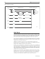
Interfaces ........................................................................................................
Naming Interfaces ...........................................................................................
Ethernet Ports .................................................................................................
Asynchronous Port ..........................................................................................
Asynchronous Call Control (ACC) .............................................................
Synchronous Ports (AR410 only) ......................................................................
Switch Ports ....................................................................................................
Port Speed and Duplex Mode ...................................................................
Limiting Switch Traffic (AR410 only) ..........................................................
Packet Storm Protection (AR450 only) ......................................................
Virtual LANs ....................................................................................................
Point to Point Protocol (PPP) ............................................................................
Dynamic PPP Interfaces and PPP Templates ...............................................
PPPoE .......................................................................................................
Frame Relay (AR410 only) ...............................................................................
Integrated Services Digital Network (ISDN) (AR410 only) .................................
BRI Versus PRI ...........................................................................................
Configuring the Basic Rate Interface .........................................................
Configuring the Primary Rate Interface .....................................................
Default Setup ...........................................................................................
Testing the BRI or PRI PIC ..........................................................................
Configuring ISDN (AR410 only) .......................................................................
Ordering ISDN in the USA and Canada .....................................................
Configuring Basic Rate ISDN .....................................................................
Configuring Primary Rate ISDN .................................................................
Configuring ISDN Dial on Demand ...........................................................
59
60
61
62
62
63
64
64
64
65
66
67
68
68
69
69
72
72
72
72
73
73
74
74
74
77
79
Software Release 2.5.2
C613-02034-00 REV A
5
Configuring ISDN Bandwidth on Demand ................................................. 80
Installing Port Interface Cards (PICs) (AR410 only) ........................................... 81
Connecting to a Leased Line Circuit .......................................................... 81
CHAPTER 6
Routing
This Chapter ................................................................................................... 83
Configuring an IP Network ............................................................................. 83
Before You Start ....................................................................................... 84
Configuring IP .......................................................................................... 84
Configuring IP Multicasting ............................................................................. 87
Configuring IGMP .................................................................................... 88
Multicasting using DVMRP ....................................................................... 88
Configuring Dynamic Host Configuration Protocol (DHCP) .............................. 93
Configuring DHCP .................................................................................... 94
Configuring a Novell IPX Network ................................................................... 95
Before You Start ....................................................................................... 95
Configuring IPX ........................................................................................ 96
Configuring IPX Dial-on-Demand .............................................................. 99
AppleTalk ...................................................................................................... 102
Routing Information Protocol (RIP) ................................................................ 103
Resource Reservation Protocol (RSVP) ............................................................ 103
OSPF ............................................................................................................. 104
Configuring a Basic OSPF Network ......................................................... 104
CHAPTER 7
Maintenance and Troubleshooting
This Chapter .................................................................................................
How the Router Starts Up .............................................................................
How to Avoid Problems ................................................................................
What to do if you clear FLASH memory completely .......................................
What to do if ISDN Fails to Connect ..............................................................
What to do if the PPP Link Disconnects Regularly ..........................................
What to do if Passwords are Lost ..................................................................
Getting the Most Out of Technical Support ...................................................
Resetting Router Defaults .............................................................................
Checking Connections Using PING ................................................................
Troubleshooting IP Configurations ................................................................
Troubleshooting DHCP IP Addresses ..............................................................
Troubleshooting IPX Configurations ..............................................................
Using Trace Route for IP Traffic ......................................................................
Software Release 2.5.2
C613-02034-00 REV A
107
108
109
111
112
112
113
113
114
114
115
116
117
119
Chapter 1
Introduction
Introducing the AR400 Series Router
Congratulations on purchasing an AR400 Series router — the optimal solution
for your small or medium sized business.
This guide introduces the AR400 Series router and will guide you through the
most common uses and applications of your new router. Getting started will
not take long—many applications are set up in just a few minutes. If you have
any questions about the router, contact your authorised distributor or reseller.
Your AR400 Series router is supplied with default settings which allow you to
operate the router immediately, without any configuration. Even if this is all
you want to do, you should still gain access to the router configuration, if only
to change the manager password to prevent unauthorised access.
To change the switching configuration, and to take advantage of the advanced
routing features, you will need to enter detailed configuration. The router has
both a Command Line Interface (CLI) and a Graphical User Interface (GUI) for
configuration and management. Before you can use the GUI, you will need to
login to the router and use its CLI to allocate an IP address to at least one
interface.
Why Read this User Guide?
Before you use your router in a live network, please read this guide. The guide
tells you how to access and use the Command Line Interface (CLI) to configure
the router software, and how to access and use the router’s Graphical User
Interface (GUI). It then introduces a number of common router functions and
how to configure them using the CLI. For information on configuration using
the GUI, see the context-sensitive online GUI help. For more detailed
descriptions of all commands, display outputs, and background information,
see the AR400 Series Router Software Reference.
This user guide is organised into the following chapters:
■
Chapter 1, Introduction gives an overview of the router features and of the
documentation supplied with your router.
8
AR400 Series Router User Guide
■
Chapter 2, Getting Started with the Command Line Interface (CLI) describes
how to gain access to the command lineinterface.
■
Chapter 3, Getting Started with the Graphical User Interface (GUI) describes
how to access and use the graphical user interface.
■
Chapter 4, Operating the router introduces general operation, management
and support features, including loading and installing support files and
new releases.
■
Chapter 5, Physical and Layer 2 Interfaces describes how to configure Layer 2
switching features, including switch ports and VLANs.
■
Chapter 6, Routing describes how to configure routing over VLANs and
other Layer 3 interfaces, and the load balancer feature.
■
Chapter 7, Maintenance and Troubleshooting describes some of the commands
you can use to monitor the router and diagnose faults.
Where To Find More Information
Before installing the router and any expansion options, read the important
safety information in the AR400 Series Router Safety and Statutory Information
booklet.
Follow the Quick Install Guides’ step-by-step instructions for physically
installing the router and any expansion options.
The AR Series Router Hardware Reference gives detailed information about the
equipment hardware.
The context-sensitive online GUI help gives descriptions of each page and
element of the GUI.
Once you are familiar with the basic operations of the router, use the AR400
Series Router Software Reference for full descriptions of routing features and
command syntax.
The AR400 Series Router Documentation Set
The documentation set for the AR400 Series router includes:
■
AR400 Series Router Safety and Statutory Information
■
AR400 Series Router Quick Install Guide (for AR410 and AR410S)
■
AR450S Router Quick Install Guide
■
AR400 Series Router Documentation and Tools CD-ROM
The AR Series Router Documentation Set in Adobe Acrobat PDF format is
bundled with every router—the complete reference to installing,
configuring and managing the router, including detailed descriptions of all
commands.
The CD-ROM includes the following PDF documents:
•
AR400 Series Router Safety and Statutory Information
•
AR400 Series Router Quick Install Guide (for AR410 and AR410S)
•
AR450S Router Quick Install Guide
•
AR Series Router Hardware Reference
Software Release 2.5.2
C613-02034-00 REV A
Introduction
9
•
AR400 Series Router Software Reference
•
Port Interface Card Quick Install Guide (for AR410 and AR410S)
•
Port Interface Card Hardware Reference (for AR410 and AR410S)
The CD-ROM also includes:
•
Application Notes—a collection of technical and background papers on
the application of AR400 router technologies.
•
Configuration Examples—a collection of ready-to-use examples of
typical network configurations, complete with scripts to download to
an AR400 router using AT-TFTP.
•
AT-TFTP Server for Windows, for downloading software releases,
scripts and other files to or from an AR400 router.
•
Adobe Acrobat Reader for Windows for viewing and printing the
online documentation in PDF format. Get instant access to information
with full-text searching of PDF documents by keyword or phrase.
•
Microsoft Internet Explorer.
•
Demonstration versions of networking utilities, such as AR-Remote File
Manager (AR-RFM) from Allied Telesyn and F-Secure’s Secure Shell
client for Windows.
•
Information about other Allied Telesyn routing and switching
products.
Online Technical Support
For online support for your AR400 Series router, see our online support page at
http://www.alliedtelesyn.co.nz/support/ar400.
This page also contains the latest router software releases, patches and GUI
resource files. Use the LOAD command to download software upgrades
directly from the Allied Telesyn web site to the router’s FLASH memory. Use
the SET INSTALL command to enable the new software (see “Upgrading Router
Software” on page 51 for detailed instructions).
If you require further assistance, contact your authorised distributor or reseller.
Features of the AR400 Series Router
The AR400 Series router supports a wide range of network interfaces which
allows you to choose the network service that is right for you.
The AR410 base unit supports:
■
four 10/100 Mbps full duplex switched Ethernet LAN ports.
■
one 10/100 Mbps full duplex Ethernet WAN port
■
one asynchronous serial port
■
one Port Interface Card (PIC) Bay
■
one internal MAC slot
You can add additional interfaces to your AR410 or AR410S by installing a Port
Interface Card (PIC) in the PIC bay.
Software Release 2.5.2
C613-02034-00 REV A
10
AR400 Series Router User Guide
The AR450S base unit supports:
■
five 10/100 Mbps full duplex switched Ethernet LAN ports.
■
two 10/100 Mbps full duplex Ethernet WAN and DMZ ports
■
two asynchronous serial ports
■
one built-in encryption processor
The software support for the AR400 Series router and the expansion options
provides wirespeed Layer 2 switching, including support for Virtual LANs. In
addition, the router provides a wide array of multiprotocol routing, security
and network management features.
Management Features
The following features enhance management of the router:
■
A sophisticated and configurable event logging facility for monitoring and
alarm notification to single or multiple management centres.
■
Triggers for automatic and timed execution of commands in response to
events.
■
Scripting for automated configuration and centralised management of
configurations.
■
Dynamic Host Configuration Protocol (DHCP) for automatically assigning
IP addresses and other configuration information to PCs and other hosts
on TCP/IP networks.
■
Support for the Simple Network Management Protocol (SNMP), standard
MIBs and the Allied Telesyn Enterprise MIB, enabling the router to be
managed by a separate SNMP management station.
■
Telnet client and server.
■
Secure Shell remote management.
■
An HTTP client that allows the direct download of files from a web server
to the router’s FLASH memory.
For complete descriptions of these software features, see the AR400 Series
Router Software Reference.
Software Features
AR400 Series routers provide efficient and cost-effective multiprotocol routing,
terminal serving and integrated network management over wide area
networks and LANs. The router can provide multiple functions
simultaneously. AR410 and AR450S models run different software suites, and
the available functionality depends on the model and hardware configuration:
■
Wide area networking via Point-to-Point Protocol.
■
Wide area networking via Frame Relay, and X.25, operating over
synchronous links up to 2Mb/s (AR410 only).
■
Basic Rate and Primary Rate access to Integrated Services Digital Network
(ISDN) services, with dial-on-demand and channel aggregation (AR410
only).
■
TCP/IP routing.
■
Novell® IPX routing.
Software Release 2.5.2
C613-02034-00 REV A
Introduction
Software Release 2.5.2
C613-02034-00 REV A
11
■
DECnet™ routing (Phase IV+ and area) (AR410 only).
■
AppleTalk routing.
■
Generic Routing Encapsulation (GRE) protocols.
■
IP multicast routing support, including Internet Group Management
Protocol (IGMP), Distance Vector Multicast Routing Protocol (DVMRP)
and Protocol Independent Multicast (PIM) Sparse and Dense Modes.
■
IPv6 routing support, including stateless address autoconfiguration, RIPv6
and ICMPv6.
■
IPv6 multicast routing support, including Multicast Listener Discovery
(MLDv2) and Protocol Independent Multicast (PIM) Sparse and Dense
Modes.
■
OSPF, RIP (IP and Novell®), SAP (Novell®), EGP and BGP routing
protocols.
■
ARP, Proxy ARP and Inverse ARP address resolution protocols.
■
Sophisticated packet filtering.
■
Bridging.
■
Van Jacobson’s header compression, STAC LZS and Predictor compression,
and hardware-based AES (AR450S only) and DES encryption.
■
Create secure Virtual Private Networks (VPNs) across the Internet or any
other public or shared IP network, using AT-VPNet.
■
Tunnelling of synchronous (HDLC) data through TCP/IP (AR410 only).
■
Access to network printers via LPD or TCP streams (AR410 only).
■
Resource Reservation Protocol (RSVP) for delivering quality of service to
application data streams.
■
TPAD support for fast credit card authorisation transactions (AR410 only).
■
A fully featured, stateful inspection firewall.
■
IPsec-compliant IP security services.
■
Integration with a Public Key Infrastructure (PKI).
■
Virtual Router Redundancy Protocol (VRRP).
■
Open Systems Interconnection (OSI) Connectionless Network Service
(CLNS).
■
Border Gateway Protocol version 4 (BGP-4).
■
Load Balancing for distributing traffic among multiple resources.
■
Software Secure Sockets Layer (SSL).
12
AR400 Series Router User Guide
Special Feature Licences
You need a special feature licence and password to activate some special
features over and above the standard software release. Typically, these special
features are covered by government security regulations. Special feature
licences and passwords are quite separate and distinct from the standard
software release licences and passwords. The features that are available and
that require special feature licences depend on region and router model. Some
of the software features that require a special feature licence are:
■
Triple DES S/W
■
DES encryption
■
Firewall SW (enabled on the AR410S and AR450S)
■
Firewall SMTP Application Gateway (enabled on the AR410S and AR450S)
■
Firewall HTTP Application Gateway (enabled on the AR410S and AR450S)
■
IPv6
■
Resource Reservation Protocol (RSVP)
■
BGP-4
■
Load balancer
Most software features that require a special feature licence are bundled into
one of the following special feature licence packs:
■
Advanced Layer 3 Feature Licence
■
Security Pack Feature Licence
For more information about purchasing special feature licences, contact your
Allied Telesyn authorised distributor or reseller. For information on how to
enable special feature licences using the CLI, see “Enabling Special Feature
Licences” on page 20.
Warning about FLASH memory
Before you start to configure your router, note that it is possible to enter
commands that can impact severely on your router’s performance.
DO NOT clear the FLASH memory completely. The software release files are
stored in FLASH, and clearing FLASH memory would leave no software to run
the router.
While FLASH is compacting, do not restart the router or use any commands
that affect the FLASH file subsystem. Do not restart the router, or create, edit,
load, rename or delete any files until a message confirms that FLASH file
compaction is completed. Interrupting flash compaction may result in damage
to files. Damaged files are likely to prevent the router from operating correctly.
For more information, see “How to Avoid Problems” on page 109 and “What to do
if you clear FLASH memory completely” on page 111.
Software Release 2.5.2
C613-02034-00 REV A
Chapter 2
Getting Started with the Command Line
Interface (CLI)
This Chapter
This chapter describes how to access the router’s CLI, and provides basic
information about configuring the router, including how to:
■
Physically connect a terminal or PC to the router (see “Connecting a
Terminal or PC” on page 14 and the Quick Install Guide).
■
Set the Terminal Communication parameters to match the router’s settings
(see “Terminal Communication Parameters” on page 14).
■
Log in to the router as a manager (see “Logging In” on page 15).
■
Configure IP addresses on the router interfaces over which you will
manage the router. This is necessary if you will access the router using the
GUI or Telnet (see “Assigning an IP Address” on page 15).
■
Set routes (see “Setting Routes” on page 17)
■
Change the management password to limit unauthorised access to the
router configuration (see “Changing a Password” on page 17).
■
Use the command line interface to control the router software, including
creating aliases for often used character sequences (see “Using the
Commands” on page 18).
■
Set the online help file to gain access to command syntax help (see “Getting
Command Line Help” on page 19).
■
Enable any special feature licences (see “Enabling Special Feature Licences”
on page 20).
■
Set the name, location and contact details for the router (see “Setting System
Parameters” on page 21).
14
AR400 Series Router User Guide
Connecting a Terminal or PC
The first thing to do after physically installing the router is to start a terminal or
terminal emulation session to access the router. Then you can use the
command line interface (CLI) to configure the router. If you wish to configure
the router using the Graphical User Interface, you must first access the CLI and
assign an IP address to at least one interface.
You can use a PC running terminal emulation software as the manager console
instead of a terminal. Many terminal emulation applications are available for
the PC, but the most readily available is the HyperTerminal application
included in Microsoft® Windows™ 95, Windows™ 98, and Windows™ 2000.
In a normal Windows™ installation HyperTerminal is located in the
Accessories group. In Windows™ 2000, HyperTerminal is located in the Start >
Programs > Accessories > Communications menu.
The key to successfully using terminal emulation software with the router is to
configure the communications parameters in the terminal emulation software
to match the default settings of the console port on the router. For instructions
on how to configure HyperTerminal, see the AR Series Router Hardware
Reference.
To start a terminal session, connect to the router in one of the following ways:
■
Connect a VT100-compatible terminal to the RS-232 Terminal Port, set the
communications parameters on the terminal (Table 1 on page 14), and
press [Enter] a few times until the router’s login prompt appears; OR
■
Connect to the COM port of a PC running terminal emulation software
such as Windows Terminal or HyperTerminal to the RS-232 Terminal Port,
set the communications parameters on the terminal emulation software
(Table 1 on page 14), and press [Enter] a few times until the router’s login
prompt appears.
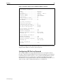
Terminal Communication Parameters
Check that the terminal or modem’s communication settings match the settings
of the asynchronous port. By default, the asynchronous port (also known as the
Console, RS-232, or Config port) on the router is set to the parameters shown in
Table 1 on page 14:
Table 1: Parameters for terminal communication
Parameter
Value
Baud rate
9600
Data bits
8
Parity
None
Stop bits
1
Flow control
Hardware
Refer to the user manual supplied with the terminal or modem for details of
how to change the communications settings for the terminal or modem.
Software Release 2.5.2
C613-02034-00 REV A
Getting Started with the Command Line Interface (CLI)
15
If a modem is connected, configure the router to make and/or accept calls via
the modem. To set the CDCONTROL parameter to “CONNECT” and the
FLOW parameter to “HARDWARE”, enter the command:
SET ASYN CDCONTROL=CONNECT FLOW=HARDWARE
If the terminal or modem is used with communications settings other than the
default settings, then configure the asynchronous port to match the terminal or
modem settings using the SET ASYN command.
See the router’s online help or the Interfaces chapter in the AR400 Series Router
Software Reference for more information on how to configure the asynchronous
port.
Logging In
When you access the router from a terminal or PC connected to the RS-232
terminal port (asyn0), or via a Telnet or HTTP connection, you must enter a
login name and password to gain access to the command prompt. When the
router is supplied, it has a manager account with an initial password friend.
Enter your login name at the login prompt:
login: manager
Enter the password at the password prompt:
password: friend
After you log into the manager account you can enter commands from this
document and from the AR400 Series Router Software Reference.
Assigning an IP Address
To configure the router to perform IP routing (for example, to access the
Internet) you need to configure IP. You also need to configure IP if you want to
manage the router from a Telnet session or with the GUI. For detailed
instructions on accessing the router with the GUI, see “Configuring the router
to access the GUI” on page 26.
First enable IP, using the command:
ENABLE IP
Then, add an IP address to each of the router interfaces that you want to
process IP traffic. These include the default VLAN (vlan1), the DMZ (vlan2,
which contains port 3, on the AR410 and AR410S; eth1 on the AR450S), and the
WAN Ethernet port (eth0).
For the default VLAN, use the command:
ADD IP INTERFACE=vlan1 IPADDRESS=ipadd MASK=mask
where:
Software Release 2.5.2
C613-02034-00 REV A
■
ipadd is an unused IP address on your LAN.
■
mask is the subnet mask (for example 255.255.255.0)
16
AR400 Series Router User Guide
If IP addresses on your LAN are assigned dynamically by DHCP, you can set
the router to request an IP address from the DHCP server, using the
commands:
ADD IP INTERFACE=vlan1 IPADDRESS=DHCP
ENABLE IP REMOTEASSIGN
You do not need to set the MASK parameter because the subnet mask received
from the DHCP server is used.
If you use DHCP to assign IP addresses to devices on your LAN, and you want to
manage the router within this DHCP regime, it is recommended that you set your
DHCP server to always assign the same IP address to the router. This will enable you
to access the GUI by browsing to that IP address, and will also let you use the router as
a gateway device for your LAN. If you need the router's MAC address for this, it can be
displayed using the command SHOW SWITCH or SHOW ETH=x MACADDRESS.
Similarly, for the default WAN Ethernet port (eth0) use the command:
ADD IP INTERFACE=eth0 IPADDRESS=ipadd MASK=mask
where ipadd is the globally-unique IP address that your ISP has assigned to
you.
For the default DMZ interface on the AR450S, use the command:
ADD IP INTERFACE=eth1 IPADDRESS=ipadd MASK=mask
where ipadd is an unused private or public IP address.
The default DMZ interface on the AR410 or AR410S is vlan2, which contains
port 3. Therefore connect your DMZ server/s to the router’s switch (network)
port 3 and give vlan2 an IP address, using the command:
ADD IP INTERFACE=vlan2 IPADDRESS=ipadd MASK=mask
where ipadd is an unused private or public IP address.
To protect servers on your DMZ (or LAN), you need to configure the firewall (see the
Firewall chapter in the AR400 Series Router Software Reference, especially the
Configuration Examples). A special feature licence is required but is enabled by default
on the AR410S and AR450S.
To change the IP address for an interface, enter the command:
SET IP INTERFACE=interface IPADDRESS=ipadd MASK=ipadd
When you are configuring the router remotely, if you change the configuration (for
example, the VLAN membership) of the port over which you are configuring, the router
is likely to break the connection.
For more information about switch ports and Virtual LANs (VLANs), see
Chapter 5, Physical and Layer 2 Interfaces in this document, and Switching on the
AR410 and Switching on the AR450 in the AR400 Series Router Software Reference.
For more information about IP addressing and routing, see Chapter 6, Routing
in this document, and the Internet Protocol (IP) chapter in the AR400 Series
Router Software Reference.
Software Release 2.5.2
C613-02034-00 REV A
Getting Started with the Command Line Interface (CLI)
17
Setting Routes
The process of routing packets consists of selectively forwarding data packets
from one network to another. Your router makes a decision to send a packet to
a particular network on information it learns dynamically from listening to the
selected route protocol and on the static information entered as part of the
configuration process. In addition, you can configure user-defined filters to
restrict the way packets are sent.
Your router maintains a table of routes which holds information about routes to
destinations. The route table tells the router how to find a remote network or
host. A route is uniquely identified by IP address, network mask, next hop,
ifIndex, protocol and policy. A list of routes comprises all the different routes to
a destination. The routes may have different metrics, next hops, policy or
protocol. A list of routes is uniquely identified by its IP address and net mask.
The routing table is maintained dynamically by using one or more routing
protocols such as RIP, EGP and OSPF. These act to exchange routing
information with other routers or hosts.
You can also add static routes to the route table to define default routes to
external routers or networks and to define subnets.
To add a static route, enter the command:
ADD IP ROUTE=ipadd INTERFACE=interface NEXTHOP=ipadd
[CIRCUIT=miox-circuit] [DLCI=dlci]
[MASK=ipadd][METRIC=1..16] [METRIC1=1..16]
[METRIC2=1..65535][POLICY=0..7] [PREFERENCE=0..65535]
To displays the entire routing table, including both static and dynamic routes,
enter the command:
SHOW IP ROUTE
For more information about setting IP routes, see the Internet Protocol (IP)
chapter in the AR400 Series Router Software Reference.
Changing a Password
You should change this password to prevent unauthorised access to the router.
Enter the command:
SET PASSWORD
The router prompts you for the current password, for the new password, and
for confirmation of the new password. The password can contain any printable
characters, and must be at least a minimum length, by default six characters.
(To change the default minimum length, see the SET USER command in the
Operations chapter, AR400 Series Router Software Reference.)
Software Release 2.5.2
C613-02034-00 REV A
18
AR400 Series Router User Guide
Choosing a Password
All users, including managers, should take care in selecting passwords. Tools
exist that enable hackers to guess or test many combinations of login names
and passwords easily. The User Authentication Facility (UAF) provides some
protection against such attacks by allowing the manager to set the number of
consecutive login failures allowed and a lockout period when the limit is
exceeded.
However, the best protection against password discovery is to select a good
password and keep it secret. When choosing a password:
■
Do make it six or more characters in length. The UAF enforces a minimum
password length, which the manager can change. The default is six
characters.
■
Do include both alphabetic (a–z) and numeric (0–9) characters.
■
Do include both uppercase and lowercase characters. The passwords
stored by the router are case-sensitive, so “bgz4kal” and “Bgz4Kal” are
different.
■
Do avoid words found in a dictionary, unless combined with other random
alphabetic and numeric characters.
■
Do not use the login name, or the word “password” as the password.
■
Do not use your name, your mother’s name, your spouse’s name, your
pet’s name, or the name of your favourite cologne, actor, food or song.
■
Do not use your birth date, street number or telephone number.
■
Do not write down your password anywhere.
Make sure you remember the new password created as you cannot retrieve a
lost password. Recovery of access to the router is complex.
Once you have logged into the manager account you are able to enter
commands from this guide and from the AR400 Series Router Software Reference.
Using the Commands
You control the router with commands described in this document and in the
AR400 Series Router Software Reference. While the keywords in commands are
not case sensitive, the values entered for some parameters are (especially
passwords). The router supports command line editing and recall. Command
line editing functions and keystrokes are shown in Table 2 on page 18.
Table 2: Command line editing functions and keystrokes .
Function
VT100 Terminal
Dumb terminal
Move cursor within command line ←, →
Not available
Delete character to left of cursor
[Delete] or [Backspace]
[Delete] or [Backspace]
Toggle between insert/overstrike
[Ctrl/O]
Not available
Clear command line
[Ctrl/U]
[Ctrl/U]
Software Release 2.5.2
C613-02034-00 REV A
Getting Started with the Command Line Interface (CLI)
19
Table 2: Command line editing functions and keystrokes (Continued).
Function
VT100 Terminal
Dumb terminal
Recall previous command
↑ or [Ctrl/B]
[Ctrl/B]
Recall next command
↓ or [Ctrl/F]
[Ctrl/F]
Display command history
[Ctrl/C] or
SHOW PORT HISTORY
[Ctrl/C]
or SHOW PORT HISTORY
Clear command history
RESET PORT HISTORY
RESET PORT HISTORY
Recall matching command
[Tab] or [Ctrl/I]
[Tab] or [Ctrl/I]
The router assumes that the width of the terminal screen is 80 characters, and
performs command line wrapping at the 80th column regardless of the setting
of the terminal. To execute a command the cursor does not need to be at the
end of the line. The default editing mode is insert mode. Characters are
inserted at the cursor position and any characters to the right of the cursor are
pushed to the right to make room. In overstrike mode, characters are inserted
at the cursor position and replace any existing characters.
Commands are limited to 1000 characters, excluding the prompt. Pathnames of
up to 256 characters, including file names, and file names up to 16 characters
long, with extensions of 3 characters, are supported.
Aliases
The command line interface supports aliases. An alias is a short name for an
often-used longer character sequence. When the user presses [Enter] to execute
the command line, the command processor first checks the command line for
aliases and substitutes the replacement text. The command line is then parsed
and processed normally. Alias substitution is not recursive—the command line
is scanned only once for aliases.
Aliases are created and destroyed using the commands:
ADD ALIAS=name STRING=substitution
DELETE ALIAS=name
Getting Command Line Help
Online help is available for all router commands. A multilingual, languageindependent online help facility provides help information via the command:
HELP [topic]
If a topic is not specified, a list of available topics is displayed. The HELP
command displays information from the system help file stored in FLASH
memory. The help file uses a simple mark-up language to identify topics,
access level (USER or MANAGER) and help text. Both standard ASCII and
Unicode character encodings are supported. Alternate help files can be
uploaded and stored in FLASH, then activated using the command:
SET HELP=helpfile
To display the current help file, enter the command:
SHOW SYSTEM
Software Release 2.5.2
C613-02034-00 REV A
20
AR400 Series Router User Guide
The help file is easily modified, for example to provide detailed site-specific
support information. The mark-up language specification and preprocessor
program are available from your authorised distributor or reseller.
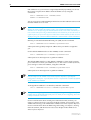
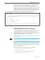
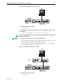
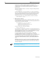
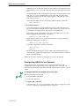
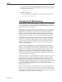
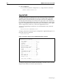
Also, typing a question mark “?” at the end of a partially completed command
displays a list of the parameters that may follow the current command line,
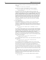
with the minimum abbreviations in uppercase letters (see Figure 1 on page 20).
The current command line is then re-displayed, ready for further input.
Figure 1: Using the question mark character (“?”) to display help for the current command.
Manager > ADD ?
Options : ACC APPletalk BGP CLASSifier BOOTp BRIDge DECnet FRamerelay GRE IP IPX
ISDN LAPD LOG MIOX NTP OSPF PERM PPP RADius SA SCript SNmp STReam STT TRIGger
TACacs USEr X25C X25T TDM
Manager > ADD ACC ?
Options : CALL SCript DOmainname
Manager > ADD ACC CALL ?
Options : DIrection DScript CScript RScript POrt ENcapsulation AUthentication
DOmainname
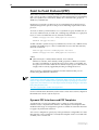
Enabling Special Feature Licences
You must enable the special feature licence you have purchased before you can
use the licenced features. You will need the password provided by your
authorised distributor or reseller. The advanced upgrade licence and password
are different from the standard software release licence and password. The
licence cannot be transferred from one router to another.
For software features that require a special feature licence see “Special Feature
Licences” on page 12.
You must order passwords for special feature licences from your authorised distributor
or reseller. You must specify the special feature licence bundle and the serial number(s)
of the router(s) on which the special feature licences are to be enabled.
The password for a special feature licence is a string of at least 16 hexadecimal
characters. This password encodes the special feature, or features, covered by
the license, and the router serial number. The password information is stored in
the router’s FLASH memory.
To enable or disable a special feature licence, enter the commands:
ENABLE FEATURE=feature PASSWORD=password
DISABLE FEATURE=feature
To list the current special feature licences, enter the command:
SHOW FEATURE[={featurename|index}]
Software Release 2.5.2
C613-02034-00 REV A
Getting Started with the Command Line Interface (CLI)
21
Setting System Parameters
You can set some general system parameters to ensure the router’s
compatibility with the public network, and to aid network administration.
Some services, for instance ISDN, use slightly different versions in different
countries. To make sure that the router uses protocols consistent with the
services it is connected to, set the system territory to the country or region in
which your router operates. Enter the command:
SET SYSTEM TERRITORY={AUSTRALIA|CHINA|EUROPE|JAPAN|KOREA|
NEWZEALAND|USA}
In Australia only: to use the Micro service, SET SYSTEM LOCATION=australia; to
use the OnRamp service, SET SYSTEM LOCATION=europe.
System name, location and contact parameters can help a remote network
administrator identify the router. By convention the system name is the full
domain name. Set the name of the router, for example:
SET SYSTEM NAME=nd1.co.nz
the location of the router, for example:
SET SYSTEM LOCATION=”Head Office, 3rd floor east”
and a contact name and phone number for the network administrator
responsible for the router, for example:
SET SYSTEM CONTACT=”Anna Brown 03-456 789”
The name, location, and contact are strings 1 to 80 characters in length of any
printable character. If the string includes spaces enclose the string in double
quotes.
Set the router’s real time clock to the current local time in 24 hour notation
(hh:mm:ss), for example:
SET TIME=14:50:00
and to the current date (dd-mmm-yy, or dd-mmm-yyyy), for example:
SET DATE=29-JAN-02
or
SET DATE=29-JAN-2003
Software Release 2.5.2
C613-02034-00 REV A
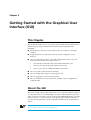
Chapter 3
Getting Started with the Graphical User
Interface (GUI)
This Chapter
This chapter describes how to access the router’s HTTP-based Graphical User
Interface (GUI), and provides basic information about using the GUI,
including:
■
About the GUI, what you can use the GUI to do, and how to navigate
within it
■
Supported browsers, and what you may need to configure on your
browser
■
How to connect the router to a PC and configure the router so you can
access the GUI, for the following scenarios:
•
a PC directly connected to the router with an Ethernet card
•
a PC in your LAN, in the same subnet as the router
•
a PC in your LAN, in a different subnet to the router
■
How to use the context sensitive GUI help
■
How to change the manager account’s password
■
How to upgrade to a new GUI resource file
■
How to troubleshoot access to the GUI, and the router’s configuration
using the GUI.
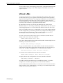
About the GUI
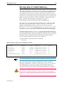
The GUI is stored on the router in the form of a resource file, with file extension
rsc. Resource files use a fixed naming convention, which includes a product
code, a language code and a version code. For the AR450S, filenames are of the
form d450se01.rsc. Resource files are model-specific, and the most recent
resource file will generally only be compatible with the most recent software
release.
If you change the GUI resource file’s name, the router will not recognise it as a valid file
and you will be unable to use it for configuration.
24
AR400 Series Router User Guide
Only one person can configure a particular router with the GUI at a time, to avoid
clashes between configurations. Monitoring and diagnostics pages can be viewed by
more than one user at a time.
The following software features can be configured through the GUI. The
position of each set of features in the GUI’s sidebar menu is also given.
Use the menus and buttons on the GUI pages to navigate, not your browser’s buttons,
to ensure that the configuration settings are saved correctly.
■
Your WAN connection to an ISP (Quick Start > WAN)
■
The IP address of the LAN interface (Quick Start > LAN)
■
System identity, time configuration and NTP, Triggers to automatically run
scripts, and SNMP (Configuration > General)
■
Ethernet and switch port configuration, including Quality of Service
(Configuration > Port)
■
VLAN configuration (Configuration > Layer 2 > VLANs)
■
PPPoE (Configuration > Layer 2 > PPPoE)
■
Internet Protocol: interfaces, static routes, RIP, multicasting, and OSPF
(Configuration > Internet Protocol)
■
DHCP server (Configuration > DHCP Server)
■
Firewall, including options for logging and alerts (Configuration >
Firewall)
The following router functionality can be managed through the GUI:
■
User accounts and enabling system security (Management > Users)
■
File creation, editing, and back-up (Management > Configuration Files)
■
Restoring the router’s configuration from backup (Management >
Configuration Files > Restore)
■
Setting the files the router uses on bootup, and a display of the current
configuration files (Management > Software > Boot Setup)
■
Enabling software release and feature licences (Management > Software >
Licences)
■
Software upgrades (Management > Software > Upgrade)
The router automatically generates log messages. Messages can be viewed
through the GUI, and filters can be set up to determine where messages are
saved to and which messages are saved (Monitoring > Log).
The following router functionality can be monitored through the GUI:
■
System status and hardware details (Monitoring > System)
■
Layer 2 forwarding database, which shows the MAC addresses that the
router’s switch ports have learned, and out which port the router will
switch traffic to each MAC address (Monitoring > L2 Fwding Database)
■
ARP table, which shows information about Address Resolution Protocol
(ARP) entries (Monitoring > ARP Table)
Software Release 2.5.2
C613-02034-00 REV A
Getting Started with the Graphical User Interface (GUI)
■
IP route table (Monitoring > IP Routes)
■
PPPoE limits (Monitoring > PPPoE Limits). Limits can also be reset from
this page.
25
The following counters can be viewed through the GUI, to show the number of
packets that the router received and transmitted for each of these protocols:
■
Port (Diagnostics > Layer 1 > Port Counters)
■
PPP (Diagnostics > Layer 2)
■
IP, ICMP and UDP, and RIP and IP routes (Diagnostics > Layer 3)
You can also view the contents of the router’s file system, see how much
memory is used and available, and delete files (Diagnostics > File System).
Finally, the GUI contains an interface to the router’s command line interface,
allowing you to enter CLI commands (Diagnostics > Command Line).
Configuring your browser to access the
GUI
The GUI requires a web browser installed on a PC. JavaScript must be enabled.
Supported browsers are:
■
Internet Explorer version 5 and greater
■
Netscape version 6.2.2 and 6.2.3
A copy of Internet Explorer can be found on the router’s Documentation and
Tools CD-ROM.
Supported operating systems are:
■
Windows 95
■
Windows 98
■
Windows ME
■
Windows 2000
■
Windows XP
The minimum screen resolution is 800x600.
You can optionally browse to the GUI with a Secure Sockets Layer (SSL)
connection. This means that sensitive data including passwords and email
addresses can not be accessed by malicious parties. For details on configuring a
SSL connection for the GUI, refer to the Configuration Example in the Secure
Sockets Layer (SSL) chapter of the AR400 Series Router Software Reference.
Software Release 2.5.2
C613-02034-00 REV A
26
AR400 Series Router User Guide
HTTP Proxy Servers
An HTTP proxy server is a server which provides a security barrier between a
private network’s PCs and the Internet. The PCs send HTTP requests (and
other web traffic) to the server, which then forwards the requests to the
appropriate next device. Similarly, the server receives incoming HTTP traffic
which is addressed to a PC on the private network, and forwards it to the
appropriate PC. Proxy servers can be used to block traffic from undesirable
websites, to log traffic flows, and to disallow cookies.
You cannot browse to the GUI through a proxy server. If your browser is set to
use a proxy server, you will need to set the browser to bypass the proxy for the
GUI’s IP address (see “Configuring the router to access the GUI” on page 26 for
information about giving the browser an IP address).
To ensure that your network’s security settings are not compromised, see your
network administrator for information about bypassing the proxy on your
system.
To bypass the proxy on Internet Explorer version 5, if your browser
administration does not use a script, and the PC and the browser are in the
same subnet:
1.
From the Tools menu, select Internet Options.
2.
Select the Connections tab and click the LAN Settings button.
3.
Check the “Bypass proxy server for local addresses” checkbox.
Configuring the router to access the GUI
You can use any VLAN or ETH port on the router to configure it via the GUI.
You must first give that VLAN or ETH port an IP address. If your router is not
in the same subnet as the PC from which you will browse to the GUI, you must
also configure routing information. For more information about IP
configuration, see the Internet Protocol (IP) chapter in the AR400 Series Router
Software Reference.
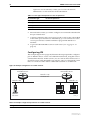
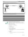
The following instructions show how to configure the router through vlan1.
The router’s five switch ports all belong to vlan1 by default. You can connect
one of the router’s switch ports directly to the Ethernet card of a PC, to
configure the router from that PC (Figure 2 on page 27). Alternatively, you can
connect one of the router’s switch ports to a device on your LAN (for example,
a hub, router or switch), and configure the router from any PC on your LAN
(Figure 3 on page 27).
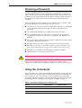
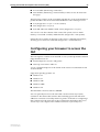
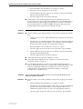
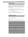
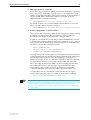
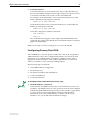
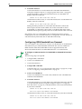
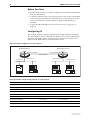
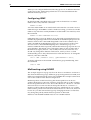
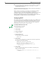
To access the GUI from a PC directly connected to the router through the
PC’s Ethernet card (Figure 2 on page 27):
1.
Plug the router in and access its command line interface.
Use a patch cable to connect any one of the router’s switch ports directly to
the Ethernet card of a PC.
Access the CLI from this PC, as described in “Connecting a Terminal or
PC” on page 14.
Software Release 2.5.2
C613-02034-00 REV A
Getting Started with the Graphical User Interface (GUI)
27
Figure 2: Connecting a PC directly to the router.
2.
Enable IP, using the command:
ENABLE IP
3. Assign the vlan1 interface an IP address in the same subnet as the PC, using
the command:
ADD IP INTERFACE=vlan1 IP=ipaddress MASK=mask
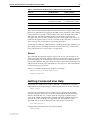
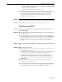
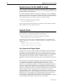
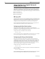
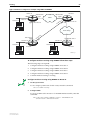
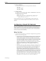
To access the GUI from a PC in your LAN, in the same subnet as the router
(Figure 3 on page 27):
1.
Plug the router in and access its command line interface.
Use a patch cable to connect any one of the router’s switch ports to a device
on your LAN (for example, a hub, router or switch).
Access the CLI from a PC that is connected to this device, as described in
“Connecting a Terminal or PC” on page 14.
Figure 3: Connecting your LAN to the router.
Hub or
switch
2.
Enable IP, using the command:
ENABLE IP
Software Release 2.5.2
C613-02034-00 REV A
28
AR400 Series Router User Guide
3. Assign the vlan1 interface an IP address in the same subnet as the PC, using
the command:
ADD IP INTERFACE=vlan1 IP=ipaddress MASK=mask
If you use DHCP to assign IP addresses to devices on your LAN, and you want to
manage the router within this DHCP regime, it is recommended that you set your
DHCP server to always assign the same IP address to the router. This will enable you
to access the GUI by browsing to that IP address, and will also let you use the router as
a gateway device for your LAN. If you need the router's MAC address for this, it can be
displayed using the command SHOW SWITCH or SHOW ETH=x MACADDRESS.
To set the interface to obtain its IP address by DHCP, use the commands ADD IP
INTERFACE=VLAN1 IPADDRESS=DHCP and ENABLE IP REMOTEASSIGN.
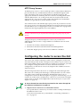
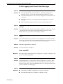
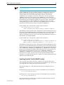
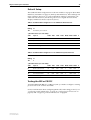
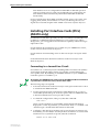
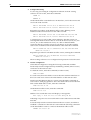
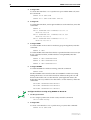
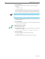
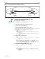
To access the GUI from a PC in your LAN, in a different subnet to the router
(Figure 4 on page 28):
1.
Plug the router in and access its command line interface.
Use a patch cable to connect any one of the router’s switch ports to a device
(for example, a hub, router or switch) on the LAN segment in which you
require the router to work.
Access the CLI from a PC connected to a COM port on the router, as
described in “Connecting a Terminal or PC” on page 14.
Figure 4: Configuring the router from a PC in another subnet.
gateway
subnet
2.
subnet
Enable IP, using the command:
ENABLE IP
3. Assign the vlan1 interface an IP address in the subnet of the LAN segment the
router will operate in, using the command:
ADD IP INTERFACE=vlan1 IP=ipaddress MASK=mask
If you use DHCP to assign IP addresses to devices on your LAN, and you want to
manage the router within this DHCP regime, it is recommended that you set your
DHCP server to always assign the same IP address to the router. This will enable you
to access the GUI by browsing to that IP address, and will also let you use the router as
a gateway device for your LAN. If you need the router's MAC address for this, it can be
displayed using the command SHOW SWITCH or SHOW ETH=x MACADDRESS.
To set the interface to obtain its IP address by DHCP, use the commands ADD IP
INTERFACE=VLAN1 IPADDRESS=DHCP and ENABLE IP REMOTEASSIGN.
Software Release 2.5.2
C613-02034-00 REV A
Getting Started with the Graphical User Interface (GUI)
29
4. Give the router a route to the PC you wish to browse from, using the
command:
ADD IP ROUTE=PC-subnet INTERFACE=vlan1
NEXTHOP=gateway-ipaddress
where:
•
PC-subnet is the IP subnet address of the PC. For example, if the PC has
an IP address of 192.168.6.1 and a mask of 255.255.255.0, its subnet
address is 192.168.6.0.
•
gateway-ipaddress is the IP address of the gateway device that connects
the PC’s subnet with the router’s subnet (Figure 4 on page 28).
Browse to the GUI from the desired PC
Once you have configured the router’s IP settings, as described in the
previous section, you can use the GUI to configure the router.
1. If you access the Internet through a proxy server (see “HTTP Proxy Servers” on
page 26), set your browser to bypass the proxy for vlan1’s IP address.
See your network administrator for information about bypassing the proxy
on your system.
2.
Point your web browser at vlan1’s IP address.
3.
At the login prompt, enter the user name and password.
User Name: manager
Password: friend
The System Status page is displayed. Select options from the sidebar menu
to configure and manage the router.
Changing the Password
As a security precaution, change the password as soon as possible.
To change the password of the default Manager account, select Management >
Users from the sidebar menu. Select the Manager account and click Modify.
For information about passwords, see “Changing a Password” on page 17.
Software Release 2.5.2
C613-02034-00 REV A
30
AR400 Series Router User Guide
Context sensitive GUI help
The GUI’s context-sensitive help system is displayed in a banner which covers
the title of the GUI page. You can move the banner to any part of your screen
and/or resize it. To display the help, click on the Help button above the sidebar
menu or on the page for which you require assistance. Three types of help are
available:
■
Click General Page Info to see brief background and process flow
information. The General Page Info displays when you click the Help
button.
■
Click Page Element Info and roll your mouse over an element, to see
information about that element.
To freeze the banner’s display so that the help does not change when you
move the mouse, press the [Ctrl] key. To unfreeze, press [Ctrl] again. Note
that element information is not available for entries in tables. To see
descriptions of the columns of tables, click Complete Help Page.
■
Click Complete Help Page to see all available information, including the
element information, in a separate printable window.
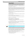
Saving Configuration Entered with the
GUI
Configuration changes applied using the GUI can be saved to a configuration
script by clicking the Save button at the top of the sidebar menu. A pop-up
Save window gives you the option of saving to the current configuration file,
another existing file, or a new file. You can also choose to use this configuration
at bootup.
When the Save button is red, this indicates that changes have been made to the
configuration and not yet saved. If you attempt to exit the GUI without saving
the configuration, a pop-up window will allow you to choose whether or not to
save.
Upgrading the GUI
You can download the latest GUI resource file from the support site at
http://www.alliedtelesyn.co.nz. Before you start, ensure that the router is running
the most recent release and patch files. To check which files it is running, refer
to the “Current Install” section of the command:
SHOW INSTALL
For troubleshooting information, see your User Guide.
To upgrade the GUI
1.
Load the new file onto the router
Download the GUI resource file from the website to your TFTP server. Do
not rename the file.
Software Release 2.5.2
C613-02034-00 REV A
Getting Started with the Graphical User Interface (GUI)
31
Load the GUI resource file from your TFTP server to the router, using the
command:
LOAD FILE=filename.rsc SERVER=server
where:
•
filename is the name of the GUI resource file, as shown on the support
site for your router. Do not rename the file.
•
server is the IP address of the TFTP server the file is loaded from.
When the router has loaded the file into its RAM, it displays the message
“File transfer successfully completed”. It then writes the file to FLASH
memory. Wait approximately 30 seconds after the message before entering
any commands that refer to this file.
2.
Install the new file as the preferred GUI
Set the new GUI resource file as the preferred resource file, using the
command:
SET INSTALL=preferred GUI=filename.rsc
You can use the GUI to load the new resource file onto the router
(Management > Software > Upgrade), but you need to use the CLI to
install the new file.
Check that the new GUI resource file is valid for your device, using the
command:
SHOW GUI
3.
If required, delete the old GUI resource file
If you do not want to keep the previous GUI resource file, delete it, using
the command:
DELETE FILE=previous-gui.rsc
where:
•
previous-gui.rsc is the name of the GUI resource file that you are
replacing.
Wait until FLASH compaction has finished. This will take several minutes.
Do not interrupt the router’s power supply during FLASH compaction, under
any circumstances.
If required, you can store more than one GUI resource file on the router at a
time. If you have multiple valid resource files stored on the router, use the SET
INSTALL command to change the resource file you use. You cannot delete the
resource file that the router is currently set to use unless you first disable the
GUI.
Software Release 2.5.2
C613-02034-00 REV A
32
AR400 Series Router User Guide
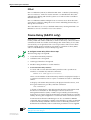
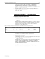
Troubleshooting
The GUI resource file has an 8-digit name, with the file extension rsc (for
example, d450se01.rsc). To check which resource files are present on the
router use the command:
SHOW FILE
To display information about the GUI resource file that is currently installed,
use the command:
SHOW GUI
To display information about the router’s HTTP server, use the commands:
SHOW HTTP SERVER
SHOW HTTP SERVER SESSION
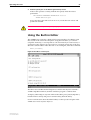
Accessing the GUI
Problem
Diagnosis
Solution
You cannot access the GUI.
Check if you can ping the router’s public interface from your PC. If you get a
response, this indicates that the public interface’s IP address is valid, and that
your PC has a route to it. Note that you will not get a response if Respond to
ping is unchecked on the Firewall Policy Options page (Configuration >
Firewall > Interfaces > Policy options). This option is checked by default.
■
If you cannot ping the router’s public interface:
•
Check that your PC’s gateway is correct, so that your PC has a route to
the router.
•
The IP address of the router’s public interface may be incorrect. To
correct this, access the CLI and use the IPADDRESS parameter of
command SET IP INTERFACE
•
The IP address of the router’s default gateway may be incorrect, so that
the router does not have a route back to your PC’s gateway. To correct
this, access the CLI and use the NEXTHOP parameter of the command
ADD IP ROUTE or SET IP ROUTE.
■
If the router should be dynamically assigned an IP address, check that the
DHCP server can reach the router, by pinging the router from the DHCP
server. Note that you will not get a response if Respond to ping is
unchecked on the Firewall Policy Options page (Configuration > Firewall >
Interfaces > Policy options tab). This option is checked by default.
■
If your PC accesses the Internet through a proxy server, you may need to
set your browser to bypass the proxy when browsing to the router’s IP
address range. See “HTTP Proxy Servers” on page 26 for more
information.
■
If you cannot access the GUI because your username or password fails,
check that you are spelling them correctly. The username “manager” will
always be valid. Its default password is “friend”. Note that passwords are
case sensitive.
Software Release 2.5.2
C613-02034-00 REV A
Getting Started with the Graphical User Interface (GUI)
33
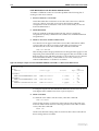
Problem
The GUI is behaving inconsistently, or you cannot access some pages.
Solution
■
Check that you are trying to access the GUI from a supported browser.
Internet Explorer 5.0 or later, and Netscape 6.2.2 and 6.2.3 are supported.
■
Check that Javascript is enabled.
Problem
The GUI does not seem to configure the router correctly.
Solution
■
Use the buttons on the GUI pages to navigate, not your browser’s Back,
Forward or Refresh buttons. The GUI’s navigation buttons perform aspects
of the configuration.
■
If you have enabled the firewall, check that your firewall access rules are
valid.
Traffic Flow and Network Address Translation (NAT)
Problem
Solutions
No traffic is passing through the router to or from the LAN, the DMZ or
both.
■
•
Check that the port is enabled (Configuration > Port > Settings)
•
Check that the IP address of the interface is still valid.
•
Check that the cables are connected correctly and function correctly.
■
If you have enabled the firewall, check that the correct interfaces are
attached to the policies (Configuration > Firewall > Interfaces > Interfaces
tab) and that your firewall access rules are valid.
■
Check the RIP configuration (Configuration > Internet Protocol > RIP).
■
Software Release 2.5.2
C613-02034-00 REV A
Check that the router’s link to the LAN is functioning, by checking that the
port has a green icon on the System Status page (Monitoring > System),
and that the link LED is lit. If the LED is not lit, or either or both interfaces
do not have an status of “active”:
•
Check that the RIP neighbour can reach the router, by pinging the router
from the RIP neighbour. Note that you will not get a response if
Respond to ping is unchecked on the Firewall Policy Options page
(Configuration > Firewall > Interfaces > Policy options tab). This option
is checked by default.
•
Any password and authentication settings must be configured on the
neighbour as well as on this router.
Check that the router is passing the correct DNS information to hosts on
the LAN, if the router is a DHCP server. If the router acting as a DHCP
client as well, and therefore is passing on DNS information from another
DHCP server, check that this DHCP server is providing the router with the
correct information.
Problem
A device on the LAN or DMZ can send some traffic out, but cannot receive
traffic.
Solution
If you are using a static Standard NAT, this problem may indicate that NAT is
mapping to an invalid IP address. To check this, select Configuration > Firewall
> NAT.
34
AR400 Series Router User Guide
Problem
Incoming traffic is sent to the wrong host.
Solution
If you are using a static Standard NAT, this problem may indicate that NAT is
mapping to a valid IP address, but which belongs to the wrong host. To correct
the IP address, select Configuration > Firewall > NAT.
Problem
Only one device on the LAN or DMZ can access the Internet.
Solution
■
If you are using a static Standard NAT, only one device from the LAN will
be able to access the Internet. If you wish to have more than one device
access the Internet, use Enhanced NAT instead (Configuration > Firewall >
NAT).
■
It is also possible that no other device has been configured with the correct
gateway.
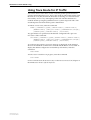
Firewall
Diagnosis
Problem
Solutions
To see information about the traffic that the firewall has denied, use the CLI
command SHOW FIREWALL EVENT=DENY
To see information about the traffic that the firewall has allowed, use the CLI
command SHOW FIREWALL EVENT=ALLOW
Legitimate traffic is not reaching your LAN or DMZ.
■
Check that a rule exists to allow the traffic (Firewall > Configuration >
Traffic Rules)
Activating a DMZ does not provide access to servers on it. Rules must be
created for each server on the DMZ. Likewise, by default there is no access
to any devices on the private LAN.
■
■
Problem
Solutions
If the rule exists, it may be incorrect or insufficient. Check that:
•
Rules intended to allow traffic have an action of “Allow”.
•
The firewall is processing the rules in the order you expected, and that
specific rules (e.g. allow IP address x access to FTP on the server) have
lower numbers than general rules (e.g. deny all FTP access).
•
The ports, services and protocols are correct.
•
The IP addresses the rules apply to are entered correctly, and belong to
the specified devices.
•
The rules apply to the correct days and time.
Check the NAT configuration. See “Traffic Flow and Network Address
Translation (NAT)” on page 33.
Illegitimate traffic is reaching your LAN or DMZ.
■
The most likely cause of this problem is an incorrect rule. Check that:
•
“Allow” rules are tight enough that only the intended traffic types are
allowed through.
•
The firewall is processing the rules in the order you expected, and that
specific rules (e.g. deny IP address x access to FTP on the server) have
lower numbers than general rules (e.g. allow all FTP access).
Software Release 2.5.2
C613-02034-00 REV A
Getting Started with the Graphical User Interface (GUI)
■
Problem
Solutions
Problem
Solutions
Software Release 2.5.2
C613-02034-00 REV A
35
•
Rules intended to block traffic have an action of “Deny”.
•
The ports, services and protocols are correct.
•
The IP addresses the rules apply to are entered correctly, and actually
belong to the specified devices.
•
The rules apply to the correct days and time.
Some traffic is allowed through the firewall, to enable the protocols to
work correctly. You can specify which ICMP traffic is allowed through on
the Firewall Policy Options page (Configuration > Firewall > Interfaces >
Policy options tab). For example, if Ping is checked on this page, ping
packets addressed to the private LAN will be allowed.
A device on your LAN or DMZ cannot access the Internet.
■
The most likely cause of this problem is an incorrect outgoing rule. Check
that:
•
“Deny” rules are not too tight and therefore blocking more traffic than
intended.
•
The firewall is processing the rules in the order you expected, and that
specific rules (e.g. allow IP address x to use FTP) have lower numbers
than general rules (e.g. deny all outgoing FTP requests).
•
Rules intended to allow traffic have an action of “Allow”.
•
The rules apply to the correct IP services (by name or port number).
•
The IP addresses the rules apply to are entered correctly, and actually
belong to the specified devices.
•
The rules apply to the correct days and time.
■
Check that the device’s gateway address is correct.
■
Check the NAT configuration. See “Traffic Flow and Network Address
Translation (NAT)” on page 33.
■
If an IP address-based rule exists to allow traffic from this particular
device, check that the device has a permanently-assigned IP address. If the
router is assigning IP addresses as a DHCP server, you can give the
required device a permanent IP address by making it a static entry
(Configuration > DHCP Server).
A device on your LAN or DMZ can access a service on the Internet even
though it should be blocked.
■
The most likely cause of this problem is an incorrect outgoing rule. Check
that:
•
Rules intended to block traffic have an action of “Deny”.
•
The firewall is processing the rules in the order you expected, and that
specific rules (e.g. block IP address x from using FTP) have lower
numbers than general rules (e.g. allow all outgoing FTP requests).
•
The rules apply to the correct IP services (by name or port number).
36
AR400 Series Router User Guide
■
•
The IP addresses the rules apply to are entered correctly, and actually
belong to the specified devices.
•
The rules apply to the correct days and time.
If an IP address-based rule exists to block traffic from this particular
device, check that the device has a permanently-assigned IP address.If the
router is assigning IP addresses as a DHCP server, you can give the
required device a permanent IP address by making it a static entry
(Configuration > DHCP Server).
Problem
You have created a Firewall rule to allow (or deny) FTP traffic, selecting FTP
as the Common Service, but passive FTP traffic is still dropped (or allowed).
Solution
The FTP service in the Common Service list is only active FTP.
IP Addresses and DHCP
Problem
You have selected Quick Start > WAN > DHCP, but the router hasn’t been
given an IP address.
Solution
■
Check that the router’s domain and host name are correct (Configuration >
System > General).
■
Check that the DHCP server can reach the router, by pinging the router
from the DHCP server. Note that you will not get a response if Respond to
ping is unchecked on the Firewall Policy Options page (Configuration >
Firewall > Interfaces > Policy options tab). This option is checked by
default.
Problem
The router is enabled as a DHCP server, but cannot assign an IP address to a
host.
Solution
■
Reboot the host machine.
■
Check the host’s TCP/IP settings, to make sure that the host is set to obtain
its IP address dynamically:
In Windows 95/98, click Settings > Control Panel > Network. Select TCP/
IP and click Properties. Click Obtain an IP address automatically.
In Windows 2000, click Settings > Control Panel > Network and Dial-up
Connections > Local Area Connection > Properties. Select Internet
connection (TCP/IP) and click Properties. Click Obtain an IP address
automatically.
■
Check that the DHCP server has a large enough range of addresses
(Configuration > DHCP Server).
■
Check that the router’s link to the LAN is functioning, by checking that the
port has a green icon on the System Status page (Monitoring > System),
and that the link LED is lit (see “Accessing the GUI” on page 32).
Software Release 2.5.2
C613-02034-00 REV A
Getting Started with the Graphical User Interface (GUI)
37
Traffic Logging and Firewall Alert Messages
Problem
Firewall Alert messages are not being emailed.
Solution
■
Check that Enable Email Firewall Alerts is checked (Configuration >
Firewall > Events > Alarms tab) and that the email address is correct.
■
Check that the DNS Server IP is correct (Configuration > Internet Protocol
> General).
■
Check that a hostname is correctly specified (Configuration > System >
General).
■
Make sure that the mail server has an account set up for the router.
Problem
You are not receiving email notifications of all attacks that the firewall
intercepts.
Solution
Your alarm thresholds may be set too high (Configuration > Firewall > Events
> Alarms tab). Be careful when reducing the thresholds, because if the
threshold is too low, your mail service may be flooded.
Problem
You are receiving email notifications for “attacks” that actually are not
attacks.
Solution
Your alarm thresholds may be set too low (Configuration > Firewall > Events >
Alarms tab). Be careful when increasing the thresholds, because if the threshold
is too high, you may not be warned about actual attack attempts.
Problem
The time in log packets is incorrect.
Solution
See “Time and NTP” on page 37.
Time and NTP
Diagnosis
The router’s time is displayed on the Configuration > System > Time tab. It will
also be included in log packets.
Problem
The router’s time does not change, even though you entered the correct time.
Solution
Changing the time is a 3-step process. Select Configuration > System > Time
tab. First, enter a time that is very shortly in the future (e.g. 20 seconds later
than the current time). Then check Set time. Then wait until precisely the time
you have entered, and click Apply.
Problem
The router is not assigning the time to devices on the LAN.
Solutions
Software Release 2.5.2
C613-02034-00 REV A
■
Check NTP is enabled (Configuration > System > Time tab).
■
Check that the NTP peer’s IP address is entered correctly.
38
AR400 Series Router User Guide
■
Check that the NTP peer can reach the router, by pinging the router from
the NTP peer. Note that you will not get a response if Respond to ping is
unchecked on the Firewall Policy Options page (Configuration > Firewall >
Interfaces > Policy options tab). This option is checked by default.
■
Check that the router’s link to the LAN is functioning. See “Traffic Flow and
Network Address Translation (NAT)” on page 33.
Problem
The router’s clock does not synchronise with the NTP peer.
Solution
■
The router’s clock can only synchronise with the NTP peer if its initial time
is similar to the NTP peer’s time (after setting the UTC offset). Manually
set the router’s time so that it is approximately correct, and enable NTP
again.
■
Check that the UTC offset is correct.
Problem
The router’s time is incorrect, even though it assigns the correct time to
devices on the LAN.
Solution
The UTC offset is probably incorrect, or needs to be adjusted for the beginning
or end of summer time. To correct this, select Configuration > System > Time
tab and enter the correct offset.
Loading Software
Problem
You have attempted to load a new release file onto the router, but the load
has failed and you cannot access the router through the GUI.
Solution
1.
Access the router’s CLI (see “Connecting a Terminal or PC” on page 14).
If the router has been switched off or has rebooted since you attempted to
load the release file, it will boot up with the default installation. This
contains the commands you require to load a file.
Log into the router using the manager account and password.
2.
Download the release file to the router. See “Example: Upgrade to a New
Software Release Using TFTP” on page 53 for an example.
Software Release 2.5.2
C613-02034-00 REV A
Chapter 4
Operating the Router
This Chapter
This chapter introduces basic operations on the router, including:
■
“User Accounts and Privileges” on page 39
■
“Normal Mode and Security Mode” on page 41
■
“Remote Management” on page 44
■
“Storing Files in FLASH Memory” on page 45
■
“Using Scripts” on page 46
■
“Loading and Uploading Files” on page 47
■
“Upgrading Router Software” on page 51
■
“Using the Built-in Editor” on page 55
■
“SNMP and MIBs” on page 56
User Accounts and Privileges
The router software supports three levels of privilege for users: USER,
MANAGER, and SECURITY OFFICER. By default, the router has one account
(manager) defined with manager privilege and the default password friend. The
commands that a user can execute depends on the user’s privilege level and
whether the router is operating in normal or security mode (see “Normal Mode
and Security Mode” on page 41). A USER level prompt looks like:
>
while a MANAGER prompt looks like:
Manager >
and a SECURITY OFFICER prompt looks like:
SecOff >
The MANAGER level has access to the full set of commands when the router is
in normal mode. When the router is operating in security mode, users with
MANAGER privilege cannot execute a subset of the commands known as the
security commands (see “Normal Mode and Security Mode” on page 41).
40
AR400 Series Router User Guide
In normal mode, a user with manager privilege can create and delete accounts
for users with any of these privilege levels. Users and passwords are managed
by the User Authentication Facility. Users and passwords are authenticated
using an internal database called the User Authentication Database, or by
interrogation of external RADIUS (Remote Authentication Dial In User Service) or
TACACS (Terminal Access Controller Access System) servers.
On the CLI, to use an account with manager privilege, log in to the account by
entering the command:
LOGIN
The router prompts you to enter a user name and password. To return to USER
mode, enter the command:
LOGOFF
Make sure that you do not leave a manager session unattended. Unauthorised
use of a manager session gives access to the User Authentication Database. To
reduce the risk of unauthorised activity, a subset of manager commands have a
security timer. These commands are shown in Table 3 on page 40. When you
enter one of these commands from a manager session, the security timer is
started and is then restarted each time you enter another of these commands. If
you enter one of these commands after the timer has expired, you are
prompted to re-enter the password. The secure delay timer is by default 60
seconds. If the password is not entered correctly the password prompt is
repeated a set number of times. If the correct password is still not entered a log
message is generated and the session is logged off.
The security timer enables a manager to make successive additions and
modifications to the database at one time without having to re-enter the
password for every command.
The security timer does not provide a foolproof security mechanism. Managers
should always attempt to log out of a manager session before leaving a
terminal unattended.
Table 3: Secure commands controlled by the security timer.
Command
Description
ADD TACACS SERVER
Adds a TACACS server to the list of TACACS servers used
for user authentication.
ADD USER
Adds a user to the User Authentication Database.
DELETE TACACS SERVER
Deletes a TACACS server from the list of TACACS servers
used for user authentication.
DELETE USER
Deletes a user from the User Authentication Database.
PURGE USER
Deletes all users except MANAGER from the User
Authentication Database.
SET MANAGER PORT
Assigns a port semipermanent MANAGER privilege.
SET USER
Modifies a user record in the User Authentication Database.
If the router is operating in security mode, the manager must also log in to a user
account with SECURITY OFFICER privilege in order to execute any of the commands
listed in Table 3 on page 40.
Software Release 2.5.2
C613-02034-00 REV A
Operating the router
41
See the Operations chapter in the AR400 Series Router Software Reference for:
■
More information about managing and using accounts with user, manager
and security officer privileges
■
A full list of commands that require security officer privilege when the
router is in secure mode
■
Information about enabling a remote security officer.
Normal Mode and Security Mode
The router operates in one of two modes, either normal mode or security
mode. By default, the router is in normal mode.
When the router is in security mode, the command SHOW DEBUG does not display
output of the SHOW FEATURE and SHOW CONFIGURATION DYNAMIC
commands, or the current configuration in the SHOW SYSTEM output unless the
SHOW DEBUG command is entered by a user with security officer privilege.
If you wish to use the following software features you need to enable security
mode:
■
IP authentication
■
Secure Shell (see the Secure Shell chapter, AR400 Series Router Software
Reference)
■
Encryption (see the Compression and Encryption Services chapter, AR400
Series Router Software Reference)
■
IPsec (see the IP Security chapter, AR400 Series Router Software Reference)
■
Public Key Encryption (PKI) (see the Public Key Infrastructure chapter,
AR400 Series Router Software Reference)
To enable security mode, first create a user with security officer privilege, then
enter the command:
ENABLE SYSTEM SECURITY_MODE
To access secure functionality you will need to log in again as the security
officer.
When the router restarts, it restarts in the same normal mode or security mode
as it was before restarting. To restore the router to normal operating mode,
enter the command:
DISABLE SYSTEM SECURITY_MODE
When security mode is disabled, the router automatically deletes all sensitive
data files, including encryption keys.
To display the current operating mode, enter the command:
SHOW SYSTEM
When the router is in security mode, a user with security officer privilege is the
only person who can execute commands which affect router security. Table 4
Software Release 2.5.2
C613-02034-00 REV A
42
AR400 Series Router User Guide
on page 42 lists commands that only a security officer can execute when the
router is in security mode. A complete list of commands limited by security
mode are listed in the Operation chapter in the AR400 Series Router Software
Reference.
Table 4: Commands requiring SECURITY OFFICER privilege when the router is
operating in security mode .
Command
Specific Parameters
ACTIVATE IPSEC
ACTIVATE SCR
ADD FR DLC
ENCRYPTION
ADD IP INT
ADD IP SA
ADD PKI
ADD SA
ADD SCR
ADD SSH
ADD USER
CREATE CONFIG
CREATE ENCO KEY
CREATE FR
DEFENCRYPTION
CREATE IPSEC
CREATE ISAKMP
CREATE PKI
CREATE PPP
CREATE PPP TEMPLATE
CREATE SA
CREATE SNMP COMMUNITY
CREATE STAR
DEACTIVATE SCR
DELETE FILE
DELELTE IP SA
DELETE PKI
DELETE SA
DELETE SCR
DELETE SSH
DELETE USER
DESTROY ENCO KEY
DESTROY IPSEC
DESTROY ISAKMP
DESTROY PKI
DESTROY SA
DESTROY STAR
DISABLE FEATURE
Software Release 2.5.2
C613-02034-00 REV A
Operating the router
43
Table 4: Commands requiring SECURITY OFFICER privilege when the router is
operating in security mode (Continued).
Command
Specific Parameters
DISABLE IPSEC
DISABLE ISAKMP
DISABLE PKI DEBUG
DISABLE SA
DISABLE SSH
DISABLE USER
DUMP
EDIT
ENABLE FEATURE
ENABLE IPSEC
ENABLE ISAKMP
ENABLE PKI DEBUG
ENABLE PPP DEBUG
ENABLE PPP TEMPLATE DEBUG
ENABLE SA
ENABLE SNMP
ENABLE SSH
ENABLE STAR
MKTTRANSFER
ENABLE USER
LOAD
MAIL
MODIFY
PURGE IPSEC
PURGE PKI
PURGE USER
RENAME FILE
RESET ENCO
RESET IPSEC
RESET USER
SET CONFIG
SET ENCO KEY
SET FR
SET INSTALL
SET IP INT
SET IPSEC
SET PKI
SET PPP
SET PPP TEMPLATE
SET SA
SET SCR
Software Release 2.5.2
C613-02034-00 REV A
ENCRYPTION, DEFENCRYPTION
44
AR400 Series Router User Guide
Table 4: Commands requiring SECURITY OFFICER privilege when the router is
operating in security mode (Continued).
Command
Specific Parameters
SET SNMP COMMUNITY
SET SSH
SET STAR
SET USER
SHOW CONFIG
SHOW ENCO KEY
SHOW FEATURE
SHOW FILE
SHOW PPP
CONFIG
SHOW STAR
[=id], MKTTRANSFER, NETKEY
UPLOAD
Remote Management
You can manage remote routers as easily as you manage the local router a
terminal is connected to. From a terminal connected to any port (with either
USER or MANAGER privilege), enter the command:
TELNET ipadd
to Telnet to the remote router, specifying the remote router’s IP address.
routerFor information about how to set routes and on how you assign an IP
address to your router, see “Setting Routes” on page 17 and “Assigning an IP
Address” on page 15.
If the connection is successful, a login prompt from the remote router is
displayed. Login using a login name that has been defined with MANAGER
privilege (such as the default MANAGER login name), and enter the
password.
To return to the local router and terminate the connection, enter the command:
LOGOFF
For more information about using Telnet, see the Terminal Server chapter in the
AR400 Series Router Software Reference.
Software Release 2.5.2
C613-02034-00 REV A
Operating the router
45
Storing Files in FLASH Memory
When you purchase the router, the router software release, the online help files,
and a default configuration file are stored in FLASH memory, where they are
saved even if the router is powered down. You will use the FLASH memory to
store updated software releases or patches, and files that record the router’s
configuration. FLASH memory is like a flat file system, with no subdirectories.
The router also has Random Access Memory (RAM). The router software uses
RAM to run the router. When you enter commands to configure the router
these commands affect the dynamic configuration in RAM.
FLASH memory is like a flat file system, with no subdirectories.
File names of up to 16 characters long, with extensions of 3 characters (DOS
16.3 format), are supported on the router. However, files on the router are
stored in FLASH using the DOS 8.3 format of 8 characters long, with
extensions of 3 characters. For example, the file extralongfilenam.cfg may
be saved as extral~1.cfg in the FLASH File System. Therefore, files can be
accessed via two file names, either of which can be used for file management.
A translation table, named longname.lfn, converts file names between DOS
16.3 format and DOS 8.3 format. To reconcile file names the router consults the
translation table which is synchronised with file contents in memory. For more
information about working with files see the Working With Files section,
Operation chapter, AR400 Series Router Software Reference.
To display the files in FLASH, enter the command:
SHOW FILE
Figure 5: Example output from the SHOW FILE command.
Filename
Device
Size
Created
Locks
---------------------------------------------------------------------------28-72.pat
flash
111764
05-May-1997 12:41:42
0
28-74ang.rel
flash
2013756 09-May-1997 15:58:55
0
28f72-06.pat
flash
123268
18-Apr-1997 15:58:16
0
release.lic
flash
32
08-May-1997 16:43:49
0
test.cfg
flash
1698
09-May-1997 10:39:42
0
sixteenalongfile.scp
flash
24
30-May-1997 15:10:12
0
----------------------------------------------------------------------------
The Locks field indicates the number of concurrent software processes using the file.
The router automatically compacts FLASH memory when a maximum
threshold of deleted files is reached. Compaction frees space for new files by
discarding garbage. A message will appear when FLASH compaction is
activated. Another message appears when FLASH compaction is complete.
While FLASH is compacting, do not restart the router or use any commands
that affect the FLASH file subsystem. Do not restart the router, or create, edit,
load, rename or delete any files until a message confirms that FLASH file
compaction is completed. Interrupting flash compaction may result in damage
to files.
Software Release 2.5.2
C613-02034-00 REV A
46
AR400 Series Router User Guide
Using Scripts
When you start or restart the router, or when it automatically restarts, it
executes the configuration commands in the boot script. A boot script is a text
file containing a sequence of standard commands that the router executes at
startup. The default boot script is called boot.cfg. Commands run from a boot
script are limited to 128 characters.
The commands you enter into the router from the command line affect only the
dynamic configuration in RAM, which is not retained over a power cycle. The
router does not automatically store these changes in FLASH memory. When
the router is restarted, it loads the configuration defined by the boot script, or if
the router was restarted using the RESTART command, any script file specified
in the RESTART command.
In addition to the boot configuration script that the router automatically runs
when it restarts, you can run a configuration script manually at any time, by
entering the command:
ACTIVATE SCRIPT=filename
You can also set a trigger to automatically execute a configuration script when
a specified event occurs.
For more information about how to create and run scripts, see the Scripting
chapter in the AR400 Series Router Software Reference.
For information about creating triggers, see the Trigger Facility chapter in the
AR400 Series Router Software Reference.
Saving the Router’s Configuration
To view the router’s current dynamic configuration, enter the command:
SHOW CONFIGURATION DYNAMIC
To save any changes made to the dynamic configuration after the router last
restarted (booted) across a restart or power cycle, and save the modified
configuration as a script file, enter the command:
CREATE CONFIG=filename.scp
To set the router to execute this script file when it restarts, enter the command:
SET CONFIG=filename.scp
The configuration file created by CREATE CONFIG command records passwords in
encrypted form, not in cleartext.
You can create a script file from any of the router software commands. These
are the same commands that are used to change the router’s configuration
dynamically. Manually edit a configuration file using the router’s built in
editor (see “Using the Built-in Editor” on page 55), or upload it to a PC using the
UPLOAD command (see the Operation chapter, AR400 Series Router Software
Reference), edit it using any text editor, and download it again. Give
configuration script files an extension of .scp or .cfg.
To display the name of the configuration file that is set to execute when the
router restarts, enter the command:
SHOW CONFIG=filename
Software Release 2.5.2
C613-02034-00 REV A
Operating the router
47
Storing Multiple Scripts
You can store multiple configuration scripts on the router. This allows you to
test new configuration scripts once, before setting them as the default
configuration. For example, to test the new configuration script test.cfg,
enter the command:
RESTART ROUTER CONFIG=test.cfg
Storing multiple scripts also allows you to keep a backup router with
configuration scripts stored on it for every router in the network to speed up
network recovery time.
Loading and Uploading Files
When you want to upgrade your router to a new software patch or release, or
use a new configuration file, load files onto the router using the router’s
LOADER module. You can also use the LOADER module to upload files, such
as configuration files or log files, from the router onto a host on the network.
File Naming Conventions
The file subsystem provides a flat file system—directories are not supported.
Files are uniquely identified by a file name of the form:
[device:]filename.ext
where:
■
device specifies the physical memory device on which the file is stored,
FLASH. If device is specified, it must be separated from the rest of the file
name by a colon (“:”). device is optional. If device is not specified, the default
is FLASH.
■
filename is a descriptive name for the file, and may be one to eight
characters in length. Valid characters are lowercase letters (a–z), uppercase
letters (A–Z), digits (0–9) and the hyphen character (-).
■
ext is a file name extension, one to three characters in length. Some file
name extensions are shown in Figure 5 on page 47. Valid characters are
lowercase letters (a–z), uppercase letters (A–Z), digits (0–9) and the hyphen
character (-). The extension is used by the router to determine the data type
of the file and how to use the file (Table 5 on page 47). If ext is specified, it
must be separated from the filename portion by a period (“.”)
Table 5: File extensions and file types .
Software Release 2.5.2
C613-02034-00 REV A
Extension
File type/function
CER
Public Key Infrastructure (PKI) certificate file.
FBR
Flash Boot software Release.
CFG
Configuration or boot script.
CRL
PKI Certificate Revocation List file.
CSR
PKI Certificate Signing Request file.
GIF
(Graphics Interchange Format) graphic image file.
HLP
CLI help file.
HTM
HTML file used by the HTTP server.
48
AR400 Series Router User Guide
Table 5: File extensions and file types (Continued).
Extension
File type/function
INS
Stores install information created by using the SET INSTALL
command.
JPG
(Joint Photographic Experts Group) graphic image file.
KEY
Public portion of an RSA key.
LIC
Licence information.
LOG
Log file.
MDS
Modem script.
PAT
Patch.
PAZ
Compressed patch.
REL
Software release.
REZ
Compressed release.
SCP
Script.
SPA
Spam Mail Source files, listing email addresses, identified as spam
mail sources, to be blocked by the firewall SMTP proxy, if it is
active.
SPL
VPN client.
TXT
Generic text file.
VPF
Future VPN client.
LFN
Extension used for the long file name translation table
You may see files on your router with file name extensions not listed in Table 5
on page 47. If you require more information about file types and file name
extensions, contact your authorised distributor or reseller.
Do not change the header in a release or patch file. At best, this will cause the
file load or install to fail, at worst the router could be put into a state where it
will not boot correctly until field service action is taken.
Loading Files
The LOADER module is responsible for loading and storing releases, patches,
PKI certificates and other files into FLASH. The LOADER module uses the
Trivial File Transfer Protocol (TFTP), Hypertext Transfer Protocol (HTTP), or
ZMODEM over an asynchronous port, to retrieve files from a network host.
You can also load text files without using any of these protocols. For
information about using Lightweight Directory Access Protocol (LDAP) to
load PKI certificates or certificate revocation lists (CRLs), see the Operation
chapter in the AR400 Series Router Software Reference.
The router’s default download method is TFTP. To load a file onto the router
from a TFTP server using the TFTP protocol, enter the command:
LOAD [METHOD=TFTP] [DELAY=delay] [DESTFILE=destfilename]
[DESTINATION={BOOTBLOCK|FLASH}] [SERVER={hostname|ipadd}]
[SRCFILE|FILE=filename]
Software Release 2.5.2
C613-02034-00 REV A
Operating the router
49
To load a file onto the router using the HTTP protocol, enter the command:
LOAD [METHOD={HTTP|WEB|WWW}] [DELAY=delay]
[DESTFILE=destfilename] [DESTINATION=BOOTBLOCK|FLASH}]
[HTTPPROXY={hostname|ipadd} [PASSWORD=password]
[PROXYPORT=1..65535]] [SERVER={hostname|ipadd}]
[SERVPORT={1..65535|DEFAULT}] [SRCFILE|FILE=filename]
[USERNAME=username]
The router can only load one file at a time. Wait for the current transfer to
complete before initiating another transfer. To display the default configuration
of the LOADER module, and the progress of any current transfer, enter the
command:
SHOW LOADER
To stop a load at any time, leaving the LOADER module ready to load again,
enter the command:
RESET LOADER
Setting LOADER Defaults
You are likely to repeat the process of downloading files onto the router using a
similar method each time. You can set defaults for some or all of the LOADER
parameters. You can then use or override some or all of these defaults for each
particular load.
To set LOADER defaults, enter the command:
SET LOADER [ATTRIBUTE={CERT|CRL|CACERT|DEFAULT}]
[BASEOBJECT={dist-name|DEFAULT}] [DELAY={delay|DEFAULT}]
[DESTFILE=dest-filename] [DESTINATION={FLASH|DEFAULT}]
[HTTPPROXY={hostname|ipadd|DEFAULT}]
[METHOD={HTTP|LDAP|TFTP|WEB|WWW|ZMODEM|NONE|DEFAULT}]
[PASSWORD=password] [PROXYPORT={1..65535|DEFAULT}]
[{SCRFILE|FILE}=filename]
[SERVER={host-name|ipadd|DEFAULT}]
[SERVPORT={1..65535|DEFAULT}] [USERNAME=username]
You can set all parameters except DESTFILE, SCRFILE and FILE back to the
factory defaults with the option DEFAULT.
For more information about setting the LOADER defaults on your router, see
the Operations chapter in the AR400 Series Router Software Reference.
Example: Load a Patch File Using HTTP
This example loads a patch file onto the router from a HTTP server on the
network. Before following this procedure, make sure:
Software Release 2.5.2
C613-02034-00 REV A
■
The HTTP server is operating on a host with an IP address (for example
192.168.1.1) on the network, and that the patch file is in the server’s HTTP
directory.
■
The router has an IP address (for example 192.168.1.2) on the interface
connecting it to the HTTP server, and that it can communicate with the
server.
■
There is enough space in the router’s FLASH for the new patch files.
50
AR400 Series Router User Guide
To load a patch file
1.
Configure the LOADER.
Set the LOADER module with defaults to make the process of
downloading files in future simpler.
SET LOADER METHOD=HTTP SERVER=192.168.1.1
DESTINATION=FLASH
2.
Download the patch file.
Download the patch file onto the router, using the defaults set above.
LOAD FILE=52232-01.paz
When the download has completed, check that the file is in FLASH.
SHOW FILE
This shows the file 52232-01.paz is present.
To activate the patch see “To upgrade to a new patch file:” on page 54.
Uploading Files From the Router
The LOADER can upload files from the router to a network host, using TFTP or
ZMODEM. Upload files using one of the commands:
UPLOAD [METHOD=TFTP] [FILE=filename]
[SERVER={hostname|ipadd}]
UPLOAD [METHOD=ZMODEM] [FILE=filename] [ASYN=port]
The UPLOAD command uses defaults set with the SET LOADER command,
for parameters not specified with the upload command.
You can install Allied Telesyn’s Trivial File Transfer Protocol Server (AT-TFTPD
on any PC or server running Windows. This will provide a simple way to make
files available to all Allied Telesyn routers and layer 3 switches in your
network. The TFTP Server, and a readme file describing how to install and use
it, are provided on the AR400 Series Router Documentation and Tools CD-ROM.
Example: Upload a Configuration File Using TFTP
This example uploads a configuration file from the router to a TFTP server on
the network. Before following this procedure, make sure:
■
The TFTP server is operating on a host with an IP address (for example
192.168.1.3) on the network.
■
The router has a valid IP address (for example 192.168.1.2) on the interface
connecting it to the TFTP server, and that it can communicate with the
server.
■
The configuration file is present in the router’s FLASH.
To upload a log file:
1.
Configure the LOADER.
Set the LOADER module with defaults to make the process of
downloading and uploading files in future simpler.
SET LOADER METHOD=TFTP SERVER=192.168.1.3
Software Release 2.5.2
C613-02034-00 REV A
Operating the router
51
2.
Upload the configuration file.
Upload the log file from the router into the TFTP directory of the TFTP
server on the network, using the defaults set above.
UPLOAD FILE=filename.log
Monitor the load progress.
SHOW LOAD
When the upload is complete, check that the file is in the TFTP directory on
the network host.
More information
For more information about loading files onto and uploading files from the
router, including using LDAP to load PKI certificate information, see the
Operation chapter in the AR400 Series Router Software Reference.
Upgrading Router Software
When you first start the router, it automatically loads the software release from
FLASH memory into RAM, where the CPU uses it to run all the router’s
software features. The router may also load a patch file to improve the main
release. The software release and any patch files are current when the router is
produced at the factory.
When Allied Telesyn makes a new patch or release available, you may want to
upgrade the software on your router to use a new patch or release file. You can
download the latest software patches, full software releases, and CLI help files
from the support site at: http://www.alliedtelesyn.co.nz/support/ar400.
Make sure you download a patch or release file that matches your router
model. A patch or release file for an AR410 or AR410S has 52 as the first two
digits of the filename. A patch or release file for an AR450S has 54 as the first
two digits of the filename. Patch files have the file extension .paz and release
files have the file extension .rez. For example, the Software Release 2.5.2 for
the AR450S has the filename 54-252.rez.
Release and patch files are compressed ASCII files, and consist of a header
followed by a sequence of Motorola S-records containing the actual code for
the release or patch. The header has a standard format, which provides
information about the release or patch to the router.
Do not change the header in a release or patch file. At best, this will cause the
file load or install to fail, at worst the router could be put into a state where it
will not boot correctly until field service action is taken.
The current release and patch file are set as the preferred install. The router also
has a very limited version of the software stored in permanent memory
(EPROM). You cannot delete this version as it is the default, or boot install.
When you load a new software release or patch, you can set it to run once, the
next time the router reboots. This temporary install allows you to test run a
new release or patch once, before you make it the preferred install. If the
Software Release 2.5.2
C613-02034-00 REV A
52
AR400 Series Router User Guide
temporary install fails the router will automatically run the preferred install if
there is one, or otherwise the default install, the next time the router reboots.
When the router reboots, it checks the install information in a strict order:
•
Firstly, the router checks the temporary install. If a temporary install is
specified, the router loads it into RAM and runs it. At the same time, it
deletes the temporary install information so it will not load a second
time. This information is deleted even if the temporary install triggers a
fatal condition causing the router to reboot immediately.
•
Secondly, if no temporary install is defined, or the install information is
invalid, the router checks the preferred install. If present, this install is
loaded. The router never deletes the preferred install information.
•
Thirdly, if neither a temporary install nor a preferred install is specified,
the router loads the default install. The default install is always present
in the router because if, for some reason, it is not, the INSTALL module
will restore it.
The preferred install should not be set up with an untested release or patch. It
is advisable to install new releases or patches as the temporary install, and
when the router boots correctly, to then set up the preferred install with the new
release or patch.
To change the install information in the router, enter the command:
SET INSTALL={TEMPORARY|PREFERRED|DEFAULT}
[RELEASE={release-name|EPROM}] [PATCH=patch-name]
For security reasons the SET INSTALL command is only accepted if the user has
SECURITY OFFICER privilege.
When you set a patch file as part of a temporary install or permanent install,
you must also set the corresponding release file in the same command, if it has
not already been set as part of that install. You can set the patch, but not the
release (always EPROM), for the default install.
To delete a temporary install or preferred install, enter the command:
DELETE INSTALL={TEMPORARY|PREFERRED}
If a default install is set, only the patch information is deleted using the
DELETE INSTALL command as the release information must always be left
intact in the default install.
To display the current install information, including which install is currently
running in the router, and how the install information was checked at the last
reboot, enter the command:
SHOW INSTALL
For more information about INSTALL commands, see the Operations chapter in
the AR400 Series Router Software Reference.
Software Release 2.5.2
C613-02034-00 REV A
Operating the router
53
Example: Upgrade to a New Software Release Using
TFTP
This example assumes the router is correctly configured to allow TFTP to
function. This means that IP is configured and the router is able to
communicate with the designated TFTP server. The TFTP server is assumed to
function correctly and the release and patch files are assumed present in the
server’s TFTP directory. The router has no release or patch files, and is running
the EPROM Software Release 2.3.2. The IP address of the server is 172.16.1.1.
The name of the release file being loaded is 52-241.rez.
To upgrade to a new software release:
1.
Configure the LOADER.
The LOADER module is set up with defaults to make the process of
downloading files in future simpler. All release and patch files in this
router are stored in FLASH.
SET LOADER METHOD=TFTP SERVER=172.16.1.1 DEST=FLASH
2.
Load the new release file onto the router.
Make sure there is space in FLASH for the new release file. Load the new
file onto your router. Make sure the release file matches your router model
(see “Upgrading Router Software” on page 51). Load any patch files
required, and the help file for the release (see “Loading and Uploading Files”
on page 47). To load the release file using your LOADER default settings,
enter the command:
LOAD FILE=52-241.rez
Wait for the release to load. This can take several minutes, even if you are
loading the file over a high speed link. To see the progress of the load, enter
the command:
SHOW LOAD
To check that the files are successfully loaded, enter the command:
SHOW FILE
3.
Enter licence information for the release.
Enter the licence password for the software release.
ENABLE RELEASE=52-241.rez PASSWORD=ce645398fbe
NUMBER=2.4.1
The release licence password is provided by your authorised distributor or
reseller and is unique for the release number (in this case 2.4.1), the file
name and the router’s serial number.
Enter passwords for any special feature licences.
ENABLE FEATURE=feature PASSWORD=password
4.
Test the release.
Set the new release to run as a temporary install. This sets the router to load
the new release once only when it reboots.
SET INSTALL=TEMPORARY RELEASE=52-241.rez
[PATCH=52241-01.paz]
If you want to use the current router configuration again, store the
dynamic configuration as a configuration script file and set the router to
use this configuration when it restarts. Releases are generally backward-
Software Release 2.5.2
C613-02034-00 REV A
54
AR400 Series Router User Guide
compatible, so your current configuration should run with little or no
modifications on the later release.
CREATE CONFIG=myconfig.cfg
SET CONFIG=myconfig.cfg
The SET CONFIG information survives the release update.
Reboot the router.
RESTART REBOOT
The router reboots, loading the new release file and the specified
configuration. Display the install history, and check that the temporary
release was loaded.
SHOW INSTALL
5.
Make the release the default (permanent) release.
If the router operates correctly with the new release, make the release
permanent.
SET INSTALL=PREFERRED RELEASE=52-241.rez
Every time the router reboots from now on, it loads the new release from
FLASH.
Example: Upgrade to a new patch file
Use this procedure to upgrade the software release currently running on the
router with a new patch. This example assumes that the current release,
Software Release 2.3.2, is set as the preferred release.
To upgrade to a new patch file:
1.
Load the new patch file onto the router.
Load the new file onto your router. See “Loading and Uploading Files” on
page 47.
LOAD FILE=52232-02.paz
Check that the file is successfully loaded.
SHOW FILE
2.
Test the patch.
Set the release to run as a temporary install, so that it loads the patch once
only the next time it reboots.
SET INSTALL=TEMPORARY RELEASE=52-232.rez
PATCH=52232-02.paz
If you want to use the current router configuration again, store the
dynamic configuration as a configuration script file, and set the router to
use this configuration when it restarts.
CREATE CONFIG=myconfig.scp
SET CONFIG=myconfig.scp
Reboot the router.
RESTART REBOOT
The router reboots, loading the new patch file and the specified
configuration. Check that the router operates correctly with the new patch
file.
Software Release 2.5.2
C613-02034-00 REV A
Operating the router
55
3.
Make the patch part of the default (permanent) release.
If the router operates correctly with the new patch, make the release
permanent.
SET INSTALL=PREFERRED RELEASE=52-232.rez
PATCH=52232-02.paz
Every time the router reboots from now on, it loads the new release and
patch from FLASH.
Do not set an untested patch as part of the preferred install.
Using the Built-in Editor
The AR400 Series router has a built-in full-screen text editor for editing script
files stored on the router file subsystem. Using the text editor you can run
script files manually, or set script files to run automatically at router restart, or
on trigger events. Figure 6 on page 55 shows a example screen shot of the text
editor. To start the editor with a new file or an existing file, enter the command:
EDIT [filename]
Figure 6: The editor screen layout.
The editor uses VT100 command sequences and should only be used with a
VT100-compatible terminal, terminal emulation program or Telnet client.
To display editor Help at any time while in the editor press [Ctrl/K,H]; that is,
hold down the Ctrl key and press in turn the K key then the H key.
For more information about the inbuilt editor, see the Operation chapter in the
AR400 Series Router Software Reference.
Software Release 2.5.2
C613-02034-00 REV A
56
AR400 Series Router User Guide
SNMP and MIBs
You can remotely monitor some features of the router using Simple Network
Management Protocol (SNMP).
The following MIBs are supported:
■
MIB II (RFC 1213)
■
Ethernet MIB (RFC 1643)
■
AR400 router portion of the ATI/ATKK Enterprise MIB
■
Frame Relay DTE MIB (RFC 1325)
■
Bridge MIB (RFC 1493)
■
Host Resources MIB (RFC 1514)
■
DS1, E1, DS2, and E2 Interface Types MIB (RFC 2495)
The SNMP agent is disabled by default. To enable SNMP, enter the command:
ENABLE SNMP
SNMP communities are the main configuration item in the router’s SNMP
agent, and are defined in terms of a list of IP addresses which define the SNMP
application entities (trap hosts and management stations) in the community. To
create an SNMP community, enter the command:
CREATE SNMP COMMUNITY=name [ACCESS={READ|WRITE}]
[TRAPHOST=ipadd] [MANAGER=ipadd]
[OPEN={ON|OFF|YES|NO|TRUE|FALSE}]
The community name is a security feature and you should keep it secure.
To enable the generation of authentication failure traps by the SNMP agent
whenever an SNMP authentication failure occurs, enter the command:
ENABLE SNMP AUTHENTICATE_TRAP
To enable the generation of link state traps for a specified interface, enter the
command:
ENABLE INTERFACE=interface LINKTRAP
where interface is the name of an interface, such as “vlan11”.
For more information see the Simple Network Management Protocol (SNMP)
chapter and the Interfaces chapter in the AR400 Series Router Software Reference.
To display the current state and configuration of the SNMP agent, enter the
command:
SHOW SNMP
For a detailed description of the output from the SHOW SNMP command, see
the Simple Network Management Protocol (SNMP) chapter in the AR400 Series
Router Software Reference.
For more information about the MIBs supported by the router, see Appendix C:
SNMP MIBs in the AR400 Series Router Software Reference.
Software Release 2.5.2
C613-02034-00 REV A
Operating the router
57
For More About Operations and Facilities
For more detail about operating the router, and for full command syntax
definitions, see the Operation chapter in the AR400 Series Router Software
Reference, including:
■
How to use the User Authentication Facility, RADIUS or TACACs for
authenticating users who log on to the router, and ensuring that only
authorised login accounts are used.
■
How to use the HTTP Client, which you can use to download software files
onto the router, and the HTTP Server.
■
How to use the Mail Subsystem.
■
How to use LDAP to load PKI certificates and CRLs onto your router.
■
How to use Switch Startup Operations
■
How to use FLASH compaction to regain storage space on the router. Read
“Warning about FLASH memory” on page 12 before you attempt to do this.
■
How to set aliases to represent common command strings.
■
How to define a remote security officer, so you can manage the security
features remotely via Telnet.
See other chapters in the AR400 Series Router Software Reference for more
information on how to:
Software Release 2.5.2
C613-02034-00 REV A
■
Use the logging facility to monitor network activity and to select and
display the results (see the Logging Facility chapter).
■
Use SNMP to manage the router remotely (see the Simple Network
Management Protocol (SNMP) chapter and Appendix C: SNMP MIBs).
■
Use the command line to create, delete and modify configuration scripts
(see the Scripting chapter).
■
Set up triggers to automatically run specified scripts at specified times, or
at specified events (see the Trigger Facility chapter).
■
Use NTP to synchronise your router’s time clock with those of other
network devices (see the Network Time Protocol (NTP) chapter).
■
Use software to test whether the router’s hardware functions correctly (see
the Test Facility chapter).
Physical and Layer 2 Interfaces
59
Chapter 5
Physical and Layer 2 Interfaces
This Chapter
This chapter introduces the physical and logical interfaces available on the base
unit router and the optional interfaces available as expansion options for the
PIC bay. Topics covered are:
■
“Interfaces” on page 60
■
“Naming Interfaces” on page 61
■
“Ethernet Ports” on page 62
■
“Asynchronous Port” on page 62
■
“Synchronous Ports (AR410 only)” on page 64
■
“Switch Ports” on page 64
■
“Virtual LANs” on page 67
■
“Point to Point Protocol (PPP)” on page 68
■
“Frame Relay (AR410 only)” on page 69
■
“Integrated Services Digital Network (ISDN) (AR410 only)” on page 72
■
“Configuring ISDN (AR410 only)” on page 74
■
“Installing Port Interface Cards (PICs) (AR410 only)” on page 81
Once you have configured the Layer 2 interfaces, you can configure a Layer 3
protocol to route traffic between these interfaces. A simple network overview
showing the relationship between physical interfaces, data link protocols, and
network routing protocols is shown in Figure 7 on page 60.
Software Release 2.5.2
C613-02034-00 REV A
60
AR400 Series Router User Guide
Figure 7: Network overview.
Data link protocols
Physical interfaces
SYN
Network routing protocols
PPP
IP
FR
IPX
X.25 LAPB
X.25T
MIOX
X.25C
BRI
Q.931
ISDN CALL
over BRI channel
PRI
Q.931
ISDN CALL
over PRI channel
ASYN
ACC
PPP
ETH
PPPoE
PORT
VLAN
AppleTalk
DECnet
PPP (ACC/L2TP)
PPP (ACC/L2TP)
UGFIG1
Interfaces
The physical interfaces on the base unit or expansion option, sometimes called
ports, connect the router to the physical network. All data enters and leaves the
router via an interface. The interface on the router and the device at the other
end of the link must use the same encapsulations for the Layer 2 protocol.
You can use the asynchronous console port on the base unit, asyn0, to configure
the router (see “Asynchronous Port” on page 62 and the Interfaces chapter in the
AR400 Series Router Software Reference).
Additional asynchronous ports can also connect terminals, printers and
terminal ports on host computers (see the Terminal Server and the Printer Server
chapters in the AR400 Series Router Software Reference).
Switch ports are numbered from 1. By default, all switch ports are enabled and
set to autonegotiate. Autonegotiation allows switch ports to adjust their speed
and duplex mode to accommodate the devices connected to them (see “Switch
Ports” on page 64 and Switching on the AR410 and Switching on the AR450 in the
AR400 Series Router Software Reference).
Switch ports are grouped into logical interfaces called Virtual LANs (VLANs),
numbered from 1. You can create and modify the default VLAN configuration
if necessary (see “Virtual LANs” on page 67 and Switching on the AR410 and
Switching on the AR450 in the AR400 Series Router Software Reference).
Software Release 2.5.2
C613-02034-00 REV A
Physical and Layer 2 Interfaces
61
Two of the encapsulations supported for synchronous ports (AR410 only)—
Frame Relay and Point-to-Point Protocol—are described in detail in the Pointto-Point Protocol (PPP) and Frame Relay chapters in the AR400 Series Router
Software Reference.
The Basic Rate and Primary Rate ISDN interfaces (AR410 only) are described in
the Integrated Services Digital Network (ISDN) chapter in the AR400 Series Router
Software Reference.
Naming Interfaces
When you configure an interface, and configure routing over that interface,
you can refer to a physical interface by its simple name or its fully qualified
name.
The simple name for an interface is the interface type, followed by the interface
number. The interface type is an abbreviation of the full name of the interface
(see Table 6 on page 61). The fully qualified name for expansion option ports
includes the expansion bay and the number of the interface within the bay.
Table 6: Interface type names.
Type
Description
Physical interfaces
PORT
Ethernet switch port interface, numbered from 1 (including uplinks)
ASYN
Asynchronous interface
BRI
Basic Rate ISDN interface
ETH
Ethernet interface (excluding switch ports)
PRI
Primary Rate ISDN interface
SYN
Synchronous interface
Logical interfaces
VLAN
Virtual LAN interface over switch ports, numbered from 1
FR
Frame Relay interface
LAPB
X.25 LAPB interface
PPP
Point-to-Point Protocol interface
X25C
X.25 DCE interface
X25T
X.25 DTE interface
When you use commands with a physical interface as a parameter, you have
the option to use either the simple name or the fully qualified name of the
interface.
For examples of valid simple names and the equivalent fully qualified names
see the Interfaces chapter in the AR400 Series Router Software Reference.
To display a summary of all the interfaces on the router, enter the command:
SHOW INTERFACE
Software Release 2.5.2
C613-02034-00 REV A
62
AR400 Series Router User Guide
Ethernet Ports
An Ethernet interface on the router is automatically configured by the software
modules when the router starts up. No user configuration of the Ethernet
interfaces is required, except to enable other software modules to use the
interface. This is achieved by adding a software module interface and using the
clause INTERFACE=ethn, where n is the number of the Ethernet interface
being configured. For example, to add a logical interface to the IP module,
enter the command:
ADD IP INTERFACE=eth0 IPADDRESS={ipadd|DHCP}
To display the modules in the router that are configured to use an Ethernet
interface, and the encapsulations used on an interface, enter the command:
SHOW ETH=n CONFIGURATION
where n is the number of the Ethernet interface.
For more information about Ethernet interfaces and encapsulations, see the
Interfaces chapter in the AR400 Series Router Software Reference.
Asynchronous Port
Asynchronous ports are normally used to connect a terminal to the router for
configuration purposes. The default values for configurable parameters are
modified by entering the command:
SET ASYN=port-number option
The factory default settings for asynchronous ports are shown in Table 7 on
page 62.
Table 7: Factory defaults for configurable parameters for asynchronous ports.
Option
Default setting
ATTENTION
BREAK
CDCONTROL
IGNORE
DATABITS
8
DEFAULTSERVICE
FALSE
DTRCONTROL
ON
ECHO
ON
FLOW
HARDWARE
HISTORY
30
INFLOW
HARDWARE
IPADDRESS
NONE
IPXNETWORK
NONE
MAXOQLEN
0 (Unrestricted)
MTU
1500
NAME
Asyn #
OUTFLOW
HARDWARE
PAGE
22
Software Release 2.5.2
C613-02034-00 REV A
Physical and Layer 2 Interfaces
63
Table 7: Factory defaults for configurable parameters for asynchronous ports.
Option
Default setting
PARITY
NONE
PROMPT
DEFAULT (CMD>)
SECURE
ON
SERVICE
NONE
SPEED
AUTO
STOPBITS
1
TYPE
VT100
For more information about asynchronous ports, see the AR Series Router
Hardware Reference or the Interfaces chapter in the AR400 Series Router Software
Reference.
For more information about configuring PPP interfaces across an asynchronous
interfaces, see the Point to Point Protocol (PPP) chapter in the AR400 Series
Router Software Reference.
Asynchronous Call Control (ACC)
You can configure the ACC module to answer calls made to a modem
connected to an asynchronous port, to validate the user making the call and to
configure the port to the mode appropriate for the desired service. Also, you
can configure ACC to originate calls by controlling a modem attached to an
asynchronous port and to switch the port to the appropriate mode once a
connection to the remote device is established.
To assign a user an IP address and MTU (Maximum Transmission Unit) for use
with an ACC call, enter the command:
SET USER=login-name IP=ipadd MTU=mtu
To assign an IP address and MTU to the asynchronous port accessed by the
ACC call, enter the command:
SET ASYN=asyn-number IP=ipadd MTU=mtu
For more information about ACC, see the Asynchronous Call Control (ACC)
chapter in the AR400 Series Router Software Reference.
Software Release 2.5.2
C613-02034-00 REV A
64
AR400 Series Router User Guide
Synchronous Ports (AR410 only)
You can use the asynchronous console port on the base unit to configure the
router. Additional asynchronous ports can also connect terminals, printers and
terminal ports on host computers.
Your router supports synchronous interfaces with speeds of up to 2.048 Mbps,
also known as E1. The router will automatically generate a clock signal when a
DCE transition cable is connected to a synchronous interface (see the AR Series
Router Hardware Reference for details of how to construct a cable).
To set the clock speed, enter the command:
SET SYN=n SPEED=speed
For more information about synchronous interfaces, see the Interfaces chapter
in the AR400 Series Router Software Reference.
Switch Ports
A switch port is one of the physical Ethernet interfaces on the base router unit.
Each switch port is uniquely identified by a port number.
To display information about switch ports, enter the command:
SHOW SWITCH PORT[={port-list|ALL}]
All switch ports on the router are enabled by default. You can disable and
enable a switch port as required. To enable or disable a switch port, enter the
commands:
ENABLE SWITCH PORT={port-list|ALL}
DISABLE SWITCH PORT={port-list|ALL}
Port Speed and Duplex Mode
Switch ports can operate at either 10 Mbps or 100 Mbps, in either full duplex or
half duplex mode. In full duplex mode a port can transmit and receive data
simultaneously. In half duplex mode a port can either transmit or receive data,
but not at the same time. This versatility makes it possible to connect devices
with different speeds and duplex modes to different switch ports. Such
versatility also requires that each switch port knows which speed and mode to
use.
Each switch port can be either configured with a fixed speed and duplex mode,
or configured to autonegotiate speed and duplex mode with a device
connected to it to determine a speed and mode that will allow successful
transmission. Setting the switch port to a fixed speed and duplex mode allows
the port to support equipment that cannot autonegotiate. Autonegotiation
allows the switch ports to adjust their speed and duplex mode to accommodate
the devices connected to them. An autonegotiating switch port will adopt the
speed and duplex mode required by devices connected to it. If another
autonegotiating device is connected to the switch port, they will negotiate the
highest possible common speed and duplex mode. When a port at one end of
the link is set to a fixed speed (non-autonegotiating) set the port at the other
end of the link to operate at the same speed. This is because when
autonegotiation is disabled, the link partner is not able to determine the duplex
mode of the link and must be forced to use the correct mode.
Software Release 2.5.2
C613-02034-00 REV A
Physical and Layer 2 Interfaces
65
On the AR450 only, Auto MDI/MDI-X is disabled when a switch port is set to a specific
speed and duplex mode.
On the AR450 only, it is also possible to require a switch port to operate at a
single speed without disabling autonegotiation by allowing the port to
autonegotiate, but constrain the speed/duplex options to the desired
combination. For example, if one end of a link is set to AUTO and other to
100MFULL then the AUTO end will select 100MHALF operation because
without the other end autonegotiating the AUTO end has no way of knowing
that the fixed end is full duplex capable. If a particular speed is required it is
usually preferable to fix the speed/duplex combination using one of the
autonegotiating speed values. Therefore, using 100MFAUTO at one end of a
link and will allow the AUTO end to autonegotiate 100MFULL.
On the AR410 only, to change this setting use the command:
SET SWITCH PORT={port-list|ALL}
SPEED={AUTONEGOTIATE|10MHALF|10MFULL|100MHALF|100MFULL}
The SPEED parameter specifies the configured line speed and duplex mode of
the port(s). If AUTONEGOTIATE is specified, the port(s) autonegotiate the line
speed and duplex mode with the device attached to the port. If any other
option is specified, the port(s) are forced to the speed and duplex mode given.
The default is AUTONEGOTIATE.
On the AR450 only, to change this setting use the command:
SET SWITCH PORT={port-list|ALL}
SPEED={AUTONEGOTIATE|10MHALF|10MFULL|10MHAUTO|10MFAUTO|10
0MHALF|100MFULL|100MHAUTO|100MFAUTO} [other-options...]
The SPEED parameter specifies the configured line speed and duplex mode of
the port(s). If AUTONEGOTIATE is specified, the port(s) will autonegotiate the
highest mutually possible line speed and duplex mode with the link partner. If
one of 10MFAUTO, 10MHAUTO, 100MFAUTO, or 100MHAUTO is specified,
the port will autonegotiate with the link partner, but only accept operation at
the specified speed and duplex mode. If one of 10MHALF, 10MFULL,
100MHALF, or 100MFULL is specified, then autonegotiation is disabled and
the interface is forced to operate at the specified speed and duplex mode,
regardless of whether the link partner is capable of working at that speed. The
default is AUTONEGOTIATE.
Limiting Switch Traffic (AR410 only)
You can make some choices about how switch ports respond when there is
more traffic than the network or the switch ports can handle easily. Any choices
you make affect all switch ports on the base router unit.
The default settings for commands that limit traffic are adequate for most
situations.
By default, back pressure for flow control for half duplex ports is turned on:
SET SWITCH BACKPRESSURE=ON
By default, flow control using pause frames for full duplex ports is turned on:
SET SWITCH FLOWCONTROL=ON
Once the system resource becomes available the switch transmission by the
link partner of the port can resume.
Software Release 2.5.2
C613-02034-00 REV A
66
AR400 Series Router User Guide
You can set the global retransmission time delay for all switch ports operating
in half duplex mode. When the port attempts to transmit a packet and
encounters a collision, the switch stops transmission and starts a short delay
(backoff) before attempting re-transmission. If AGGRESSIVE is specified, the
time delay is shorter. If NORMAL is specified, the time delay is standard. The
default is NORMAL.
SET SWITCH BACKOFF={AGGESSIVE|NORMAL}
By default, switch ports will repeat attempts to transmit a packet until they
succeed:
SET SWITCH EXCESSIVECOLLISION=RETRY
Packet buffers available in the buffer pool are shared by all switch ports. By
default, these are allocated automatically according to the amount of traffic at
each port (ADAPTIVE). To limit the number of buffers available for any port,
enter the command:
SET SWITCH BUFFERPOOL={EQUAL|ADAPTIVE}
By default, broadcast and multicast packets are discarded if they are in excess
of 25% the line rate:
SET SWITCH BROADCASTLIMIT=ON
For more information about limiting switch traffic, see the Switching on the
AR410 chapter in the AR400 Series Router Software Reference.
Packet Storm Protection (AR450 only)
Using the packet storm protection feature, you can set limits on the reception
rate of broadcast, multicast and destination lookup failure packets. Packet
storm protection limits are set on a per port basis, beyond which each of the
different packet types are discarded.
By default, packet storm protection is set to NONE, that is, disabled. Packet
storm protection can be enabled, and each of the limits set, using the command:
SET SWITCH PORT=port-list POLARITY={MDI|MDIX}
[BCLIMIT={NONE|limit}] [DLFLIMIT={NONE|limit}]
[MCLIMIT={NONE|limit}] [other-options...]
Three sets of options are allowed for packet storm protection:
■
broadcast limit only (BCLIMIT)
■
broadcast limit and multicast limit (BCLIMIT and MCLIMIT)
■
broadcast limit, multicast limit, and destination lookup failure limit
(BCLIMIT, MCLIMIT, and DLFLIMIT)
The limit specified for each option, i.e the number of kilobytes per second
(Kbps), must be the same for all modes of storm protection selected. The limit
is set to the most recent limit specified. For example:
SET SWI PORT=1 POLARITY=MDI BCLIMIT=256 MCLIMIT=256
DLFLIMIT=256
To display the packet storm protection settings, use the command:
SHOW SWITCH PORT[={port-list|ALL}]
Software Release 2.5.2
C613-02034-00 REV A
Physical and Layer 2 Interfaces
67
For more information about limiting switch traffic, see the SET SWITCH PORT
command in the Switching on the AR450 chapter in the AR400 Series Router
Software Reference.
Virtual LANs
A Virtual LAN (VLAN) is a software-defined broadcast domain. The router’s
VLAN feature allows you to segment a network by software management to
improve network performance. You can group workstations, servers, and other
network equipment connected to the router according to similar data and
security requirements. This is done by allocating the switch ports on the router
to VLANs, each of which is a separate broadcast domain.
By default, the router has one VLAN, the default VLAN, with a VLAN
Identifier (VID) of 1. All switch ports belong to the default VLAN, and all ports
send untagged packets. You cannot delete the default VLAN from the router.
If all you want the router to do is switch traffic on your LAN using the default
VLAN configuration, you need not perform any configuration. Simply power
up the router and connect devices to the switch ports. Switch learning is
enabled by default, and all valid packets are forwarded.
To create a new VLAN on the router, specify a vlanname and VID that are
unique in the router. Enter the command:
CREATE VLAN=vlanname VID=2..4094
You cannot delete the default VLAN, but to delete other VLANs if they have no
member ports, enter the command:
DESTROY VLAN={vlanname|2..4094|ALL}
Any port in the default VLAN can be added to another VLAN, and is then
automatically removed from the default VLAN. Each port can only belong to
one VLAN. To add an untagged port to a VLAN, enter the command:
ADD VLAN={vlanname|2..4094} PORT={port-list|ALL}
To return ports to the default VLAN, enter the command:
DELETE VLAN={vlanname|2..4094} PORT={port-list|ALL}
To display the VLANs configured on the router, enter the command:
SHOW VLAN[={vlanname|1..4094|ALL}
To enable communication between ports in different VLANs, you need to
configure IP or another Layer 3 protocol over the VLAN interfaces.
For more information about VLANs, see “Virtual Local Area Networks (VLANs)”
in the Switching on the AR410 chapter or Switching on the AR450 chapter in the
AR400 Series Router Software Reference.
Software Release 2.5.2
C613-02034-00 REV A
68
AR400 Series Router User Guide
Point to Point Protocol (PPP)
The Point-to-Point Protocol (PPP) establishes a connection between the router
and a service provider, on demand. PPP provides mechanisms for transmitting
data over synchronous connections, ISDN, ACC and L2TP calls, groups of
TDM slots, and Ethernet.
Each protocol carried over PPP has an associated Network Control Protocol
(NCP) that negotiates options for the protocol and brings up the link for that
protocol.
To create or destroy a PPP interface over a synchronous port, an ISDN call, an
ACC call, a MIOX circuit, an L2TP call, a TDM group (referred to as a physical
layer) or a PPP over Ethernet service, enter the command.
CREATE PPP=ppp-interface OVER=physical-interface
DESTROY PPP=ppp-interface
To add or delete a synchronous port, an ISDN call, an ACC call, a MIOX circuit,
an L2TP call, TDM group or a PPP over Ethernet service to the PPP interface,
enter the command:
ADD PPP=ppp-interface OVER=physical-interface
DELETE PPP=ppp-interface OVER=physical-interface
where:
■
physical-interface is SYNn, ISDN-callname, ACC-callname,
MIOXn-circuitname, TNL-callname, TDM-groupname or ETHn-servicename.
For PPP over Ethernet, to specify that any service name is acceptable, use
the special service name ANY. Service names may be up to 18 characters in
length, and are usually supplied by the ISP providing the service.
There are many configurable parameters for PPP interfaces that you can
modify using the SET PPP command.
By default, Allied Telesyn routers and layer 3 switches use Link Quality Reporting
(LQR=ON) to determine link quality on PPP links. When connecting to some vendors’
routers it may be more suitable to turn LQR (link quality reporting) off on PPP links
(LQR=OFF), and instead use LCP Echo Request and Echo Reply messages to determine
link quality (ECHO=ON):
SET PPP=ppp-interface ECHO=ON LQR=OFF
For more information about PPP, see the Point to Point Protocol (PPP) chapter in
the AR400 Series Router Software Reference.
Dynamic PPP Interfaces and PPP Templates
A request from a lower layer (ISDN, ACC or L2TP) to create a new PPP
interface creates a Dynamic PPP interface. PPP templates are blueprints that
enable the full range of configuration options available on static PPP interfaces
to apply to dynamic PPP interfaces.
You can use a template to specify any of the parameters configurable on a static
PPP interface. Once a template is created, this template can be associated with
an ISDN, ACC or L2TP call.
Software Release 2.5.2
C613-02034-00 REV A
Physical and Layer 2 Interfaces
69
PPPoE
PPP over Ethernet (PPPoE) is defined in RFC 2516 “A Method of Transmitting
PPP Over Ethernet”. PPPoE is used to run PPP over the Ethernet. The same
authentication, billing and transfer systems as for PPP are then available in
Ethernet networks.
PPP over Ethernet enables multiple hosts at a remote site to share the same
access device, while providing the access control and billing functionality of
dial-up PPP connections.
The router behaves as a host, as defined in RFC 2516, creating PPP links over
Ethernet to services on remote Access Concentrators.
Frame Relay (AR410 only)
Frame Relay is a wide area network service, defined by ITU-T (formerly
CCITT), ANSI and vendor standards, to which routers may connect in order to
communicate with one another and exchange data. Frame Relay is one of the
services that you can purchase from a service provider to link several offices
together at high speed. Connections are made via synchronous lines, ISDN
calls or G.703 TDM (Time Division Multiplexing) links.
To configure Frame Relay follow these steps
The following steps are required:
1.
Create the Frame Relay interface.
2.
Add Static DLCs if required.
3.
Add Logical Interfaces if required.
4.
Enable routing modules to use the interface.
1.
Create the Frame Relay interface
To create and associate the Frame Relay interface with a synchronous
interface or an ISDN call, enter the command:
CREATE FR=n OVER=physical-interface
where n is the number of the Frame Relay interface and physical-interface is
a synchronous interface such as “syn0” or an ISDN call such as “isdn-Head
Office”.
To display each Frame Relay interface, the physical interface it uses, and
the logical interfaces it provides, enter the command:
SHOW FRAMERELAY
A feature of Frame Relay is the dialogue that the network maintains with
the devices connected to it. This dialogue is known as the Local
Management Interface (LMI). A LMI is not provided by all Frame Relay
networks. Your router supports Frame Relay networks that do not run the
LMI by allowing the configuration of static Data Link Connections (DLCs).
Parameters that affect the LMI dialogue are also set with the CREATE
command. These parameters, and the values that they can take, are defined
in the Frame Relay standards. Default values for the LMI parameters are
defined in the standards, and are used when parameters are not supplied.
Consult your Frame Relay network provider before making changes to the parameters
that affect the LMI dialogue.
Software Release 2.5.2
C613-02034-00 REV A
70
AR400 Series Router User Guide
Parameters for setting the interface defaults for encryption and
compression are also set with the CREATE command. These values are
used by all DLCs on the interface unless specifically overridden for a
particular DLC.
After the Frame Relay interface is created, to change the LMI parameters,
enter the command:
SET FRAMERELAY
You may modify any or all of the parameters on a single command line.
However, only ENCAPSULATION, NT1, NN1, NN2 and NN3 parameter
changes take effect immediately. All other parameter changes cause the
Frame Relay interface to reset automatically before they take effect.
To display the current values of the parameters, enter the command:
SHOW FRAMERELAY CONFIG
2.
Add static DLCs if required
If the LMI dialogue is turned off for a Frame Relay interface, the router is
not informed about active DLCs. Therefore you must set up static DLCs. To
set up static DLCs, enter the command:
ADD FRAMERELAY=fr-interface DLC=dlci
[COMPRESSION={DEFAULT|ON|OFF}]
[ENCAPSULATION={DEFAULT|IETF|CISCO}]
[ENCRYPTION={DEFAULT|ON|OFF}]
To remove static DLCs, enter the command:
DELETE FRAMERELAY DLC
If no encryption or compression parameters are specified when the DLC is
added, the interface defaults, which are set via the DEFENCRYPTION and
DEFCOMPRESSION parameters of the CREATE FRAMERELAY and the
SET FRAMERELAY commands, are used for the DLC.
To set the encryption and compression parameters, and the CIR
(Committed Information Rate), of an individual DLC, use the SET
FRAMERELAY DLC command. If a parameter is set to a non-default value
for a DLC that the router is not informed about by the LMI, a DLC is
created to record this information. The DLC is put into the AWAIT_LMI
state until the network informs the router via the LMI that the DLC is
active.
Obtain the actual values to use for DLCs from the administrators of the
Frame Relay network to which your router is connected. Communication
across the Frame Relay network will only occur for those DLCs that are
statically configured.
If the LMI dialogue is enabled it is not possible to use static DLCs. In this case, DLCs
are learned through the LMI dialogue.
Software Release 2.5.2
C613-02034-00 REV A
Physical and Layer 2 Interfaces
3.
71
Add logical interfaces if required
Frame Relay logical interfaces (FRLI) provide a mechanism for organising
DLCs into groups. Each FRLI, or group of DLCs, are assigned its own IP
address to split the Frame Relay network into subnets. A default FRLI 0 is
always created when a Frame Relay interface is created. To create
additional FRLI’s, enter the command:
ADD FRAMERELAY=fr-interface LI=logical-interface
By default, all DLCs are associated with the default FRLI 0. To associate
DLCs with other FRLIs, enter the command:
SET FRAMERELAY=fr-interface DLC=dlci LI=logical-interface
4.
Enable routing modules to use the interface
Once a Frame Relay interface is defined and configured, configure routing
modules to use the interface. The procedures for achieving this are
described in the chapter for the particular routing module.
In general, commands that contain the parameter INTERFACE= can refer
to a Frame Relay interface by name. The form of the name is “frn”, where n
is the instance for the Frame Relay module. Examples of commands that
can refer to a Frame Relay interface include:
ADD IP INTERFACE=FRn...
ADD IPX CIRCUIT=circuit INTERFACE=FRn...
SET DNT ADD=INTERFACE INTERFACE=FRn...
One important point concerning the use of Frame Relay interfaces by the IP
routing module is the way that the IP routing module maps IP addresses to
a Frame Relay DLCI and vice versa. This mapping is an example of
Address Resolution Protocol or ARP. Two methods of ARP are supported
for Frame Relay interfaces on the router, Inverse ARP and static ARP.
The router supports the Inverse ARP, a protocol specially developed for
Frame Relay that involves the exchange of packets between routers
connected by a DLC in order to map an IP address to a Data Link
Connection Identifier (DLCI). Inverse ARP is described in RFC 1293.
To enable the router to communicate with DTEs that do not support
Inverse ARP, static ARP entries are added, by entering the command:
ADD IP ARP=ipadd INTERFACE=FRn DLCI=dlci
The use of static DLCs and static ARP information is not normally required for
interoperation of the router with other vendors’ equipment. These facilities are provided
for interoperation with equipment that does not fully support the Frame Relay
standards. Networks that consist purely of routers that support Inverse ARP will not
need static ARPs.
Software Release 2.5.2
C613-02034-00 REV A
72
AR400 Series Router User Guide
Integrated Services Digital Network
(ISDN) (AR410 only)
To use ISDN connections with an AR400 Series router you need to install the
appropriate Port Interface Card (PIC) in the router’s PIC bay. Either install an
ISDN Basic Rate ISDN (BRI) or Primary Rate ISDN (PRI) PIC. Depending on
the PIC installed, the router supports the following types of ISDN connections:
■
Basic Rate ISDN (U)
■
Basic Rate ISDN (S/T)
■
Primary Rate ISDN
BRI Versus PRI
LAPD is the Link Access Protocol for the ISDN D channel, as defined by ITU-T
Recommendation Q.921. The major difference between Basic and Primary Rate
Interfaces as far as LAPD is concerned is that BRI S/T interfaces use a bus
configuration whereas PRI interfaces use a point-to-point configuration.
For more information about ISDN, see the Integrated Services Digital Network
(ISDN) chapter in the AR400 Series Router Software Reference.
Configuring the Basic Rate Interface
The Basic Rate Interface (BRI) software module does not require user
configuration for normal ISDN operation, but may require configuration when
the interface is used for semipermanent connections.
To display the status of the BRI, enter the command:
SHOW BRI STATE
For more information about configuring BRI, see the Integrated Services Digital
Network (ISDN) chapter in the AR400 Series Router Software Reference.
Configuring the Primary Rate Interface
The Primary Rate Interface (PRI) software module requires minimal user
configuration for normal operation. Commands are provided to change userconfigurable parameters, show the status of the module, and to examine and
reset a number of data and error counters. You can reset the PRI software
module, but this should not be necessary during normal operation. The PRI
software module requires configuration for E1 and T1 interfaces.
To display the status of the PRI, enter the command:
SHOW PRI STATE
To show the higher layer modules (if any) that are attached to the PRI interface,
enter the command:
SHOW PRI CONFIGURATION
For more information about configuring PRI, see the Integrated Services Digital
Network (ISDN) chapter in the AR400 Series Router Software Reference.
Software Release 2.5.2
C613-02034-00 REV A
Physical and Layer 2 Interfaces
73
Default Setup
The standard LAPD configurations are shown in Table 8 on page 73 (Basic Rate
Interfaces) and Table 9 on page 73 (Primary Rate Interfaces). These settings suit
many situations. However, you can modify these settings as required to suit
other network situations (see the Integrated Services Digital Network (ISDN)
chapter, AR400 Series Router Software Reference).
Table 8: Standard LAPD configuration for an ISDN Basic Rate Interface.
Mode
Auto
Debug Off
TEI
Provided by the network
T, N and k values (for each SAPI):
SAPI
Layer 3
T200 T201 T202 T203 N200 N201 N202 k
0
Q.931 Call Control
10
10
20
100
3
260
3
1
1
Q.931 Packet Mode
10
10
20
100
3
260
3
3
16
X.25 Packet Mode
10
10
20
100
3
1024 3
3
63
LAPD Management
10
10
20
100
3
260
1
3
Table 9: Standard LAPD configuration for an ISDN Primary Rate Interface.
Mode
nonAuto
Debug Off
TEI
0
T, N and k values (for each SAPI):
SAPI
Layer 3
T200 T201 T202 T203 N200 N201 N202 k
0
Q.931 Call Control
10
N/A
N/A
100
3
260
N/A
7
1
Q.931 Packet Mode
10
N/A
N/A
100
3
260
N/A
7
16
X.25 Packet Mode
10
N/A
N/A
100
3
1024 N/A
7
63
LAPD Management
10
N/A
N/A
100
3
260
7
N/A
Testing the BRI or PRI PIC
To test the ISDN PRI, BRI (U), or BRI (S/T) PIC you need to configure a routing
protocol such as IP or IPX to use ISDN.
For more information about configuring ISDN calls and routing protocols, see
“Configuring ISDN (AR410 only)” on page 74, “Configuring an IP Network” on
page 83, and “Configuring a Novell IPX Network” on page 95.
Software Release 2.5.2
C613-02034-00 REV A
74
AR400 Series Router User Guide
Configuring ISDN (AR410 only)
This section describes how to configure ISDN on an ISDN expansion option on
your router using the command line interface. If you want to use ISDN, your
router must have a PIC bay with the appropriate ISDN Port Interface Card
installed. Simple ISDN configurations for Basic Rate ISDN, Primary Rate ISDN,
ISDN Dial on Demand and ISDN Bandwidth on Demand are described.
ISDN on the router requires minimal user configuration, other than selecting a
territory, creating call definitions and configuring the Point-to-Point Protocol
(PPP) to use the ISDN calls. The lower layers of the ISDN protocol stack (BRI,
LAPD and Q.931) are automatically configured when the router starts up.
The factory default hardware and software settings described here are correct
for European Union (EU) countries. For other countries, contact your
authorised distributor or reseller for details of local requirements.
Ordering ISDN in the USA and Canada
In the United States and Canada, Basic Rate ISDN is provided using National
ISDN-1, 5ESS or DMS-100 formats, all of which are supported by the router. If
National ISDN-1 is available, you can select from a list of “Capability
Packages”, each providing different features. Contact your ISDN service
provider for more information. The router will accept either one or two Service
Profile Identifiers (SPIDs).
Configuring Basic Rate ISDN
To connect an AR400 Series router with an AT-AR021(U) PIC installed to a
Basic Rate ISDN service the following steps are required:
1.
Check BRI hardware configuration.
2.
Select country or territory.
3.
Set directory numbers and subaddresses (outside USA).
4.
Set switch type and SPIDs (USA only).
5.
Create call definitions.
6.
Create PPP interfaces.
To configure Basic Rate ISDN follow these steps
1.
Check BRI hardware configuration
Check that the AT-AR021(U) PIC has the correct termination for the local
conditions. The AR410 router can only operate in TE mode and is shipped
with the standard 100W termination jumpers removed. This is appropriate
for most situations, where the building wiring provides the ISDN
termination. Your authorised distributor or reseller can advise you
whether or not you should install termination jumpers.
Software Release 2.5.2
C613-02034-00 REV A
Physical and Layer 2 Interfaces
2.
75
Select country or territory.
To select the country in which the router is operated, enter the command:
SET SYSTEM TERRITORY={AUSTRALIA|CHINA|EUROPE|JAPAN|KOREA|
NEWZEALAND|USA}
The territory determines which Q.931 profile is used on the ISDN interface.
For example, to select the Q.931 profile for the United States, enter the
command:
SET SYSTEM TERRITORY=USA
If you are not sure which territory to use, contact your authorised distributor
or reseller. Failure to select the correct territory will invalidate the approval of
this product with respect to the applicable national standards for the country
in which the product is used.
For installations in the USA, go to step 4. For installations in other
countries, go to step 3.
3.
Set directory numbers and subaddresses (outside USA).
In countries other than the USA, set router’s ISDN directory numbers and
subaddresses with the command:
SET Q931=0 NUM1=number NUM2=number SUB1=subaddress
SUB2=subaddress
This step is only required if the router is sharing the ISDN S/T bus with
other ISDN devices. See the AR400 Series Router Software Reference for more
information.
Go to Step 5.
4.
Set switch type and SPIDs (USA only).
In the USA, you may need to set the ISDN switch type and SPIDs values.
Setting the system territory to USA automatically sets the ISDN switch
type to National ISDN-1. This should be correct for all new ISDN
installations. If the router is connected to another switch type, set the
switch type with the command:
SET Q931=0 PROFILE=DMS-100
for a Northern Telecom DMS-100 switch running custom software, or:
SET Q931=0 PROFILE=5ESS
for a Lucent 5ESS switch running custom software.
If the switch type is not National ISDN-1, enter the SPIDs (supplied by the
ISDN service provider) with the command:
SET Q931=0 SPID1=spid SPID2=spid
If the switch type is National ISDN-1 the router will, when first turned on,
attempt to obtain the SPIDs itself from the switch using the Auto SPID
procedures. To monitor the success of this procedure, enter the command:
SHOW Q931=0 SPID
If the Auto SPID procedure succeeds the router will either select the SPID
values to use by itself, or tell the user (in the output of the SHOW Q931=0
SPID command) how to select the SPID values.
Software Release 2.5.2
C613-02034-00 REV A
76
AR400 Series Router User Guide
If the Auto SPID procedures fail, manually enter the SPIDs with the
command:
SET Q931=0 SPID1=spid SPID2=spid
Enter directory numbers and subaddresses with the command:
SET Q931=0 NUM1=number NUM2=number SUB1=subaddress
SUB2=subaddress
The ISDN service provider must supply the directory numbers and
subaddresses. If the directory number is a full 10 digit number (3 digit area
code plus 7 digit number), the router will append the digits “0101” to the
number and attempt SPID initialisation with the result. This is known as
the Generic SPID procedure. If SPID initialisation has already taken place
and SPIDs obtained through the Auto SPID procedure, then either these
SPIDs are the same as the Generic SPID and the router will successfully
reinitialise, or the SPIDs are not the same as the Generic SPID and the
router will not initialise. In this case, the router will revert to using the
Auto SPID values.
5.
Create call definitions.
Create ISDN call definitions to enable the router to make ISDN calls to
other devices on the ISDN network. This is the only step you must
complete to configure ISDN on the router. Before a call can be made from
one router to another, create call definitions on both routers, by entering
the command:
ADD ISDN CALL=name NUMBER=number PRECEDENCE={IN|OUT}
options...
For example, a Remote Office router is to be connected to the Head Office
router via ISDN. The ISDN number of the Remote Office router is 1234567.
The ISDN number of the Head Office router is 9876543. The called party
subaddress information element (IE) is used to carry connection
information, and PPP interfaces are created explicitly to use the ISDN calls.
Either router can initiate the call, but calls from the Remote Office have
precedence. On the Head Office router, to create a call to the Remote Office
router, enter the command:
ADD ISDN CALL=ROHO OUTSUB=LOCAL SEARCHSUB=LOCAL
NUMBER=1234567 PREC=IN
On the Remote Office router, to create a call to the Head Office router, enter
the command:
ADD ISDN CALL=ROHO OUTSUB=LOCAL SEARCHSUB=LOCAL
NUMBER=9876543 PREC=OUT
Each call has the same name (ROHO), and this name is passed via the
called subaddress IE to provide identification to the remote end of the link.
Each router will search for this call using the called subaddress IE.
You must set the precedence to ensure that in the event of a call collision
(the same call made and answered at the same time), one call is completed
and other call is cleared. The direction of precedence is not important, but
set precedence to IN at one end of the call and OUT at the other end of the
call.
The ISDN number is the exact sequence required to reach the remote router
from the local router, including STD access codes and area codes. The
number may contain only decimal digits. Hyphens and other characters
will result in an error.
Check that the ISDN calls are successfully added with the command:
SHOW ISDN CALL
Software Release 2.5.2
C613-02034-00 REV A
Physical and Layer 2 Interfaces
6.
77
Create PPP interfaces.
Create PPP interfaces to use the ISDN calls. PPP provides the link layer
protocol and enables multiple network and transport layer protocols such
as IP and Novell® IPX to be carried over the same ISDN link.
For example, on the Head Office router create PPP interface 0 to use the
ISDN call ROHO, by entering the command:
CREATE PPP=0 OVER=ISDN-ROHO
On the Remote Office router, create PPP interface 0 to use the ISDN call
ROHO, by entering the command:
CREATE PPP=0 OVER=ISDN-ROHO
Check the configuration with the commands:
SHOW ISDN CALL
SHOW PPP
The call ROHO should appear in the output of the SHOW ISDN CALL
command. The output of the SHOW PPP command should show interface
ppp0 over ISDN-ROHO.
ISDN is now ready for use by routing protocols such as IP and IPX.
Configuring Primary Rate ISDN
Your AR400 Series router can operate in either TE or NT mode, using 75W or
120W termination. The router is shipped with jumpers set to TE mode, 75W
termination, Tx grounded and Rx grounded via a 100nF capacitor. This is
appropriate for most situations. Your authorised distributor or reseller can
advise you whether or not to install grounding jumpers.
The following steps are required:
1.
Check BRI hardware configuration.
1.
Select the territory.
2.
Set directory numbers and subaddresses.
3.
Create call definitions.
4.
Create PPP interfaces.
To configure Primary Rate ISDN follow these steps
1.
Check BRI hardware configuration
Check that the AT-AR021(U) PIC has the correct termination for the local
conditions. The AR410 router can only operate in TE mode and is shipped
with the standard 100W termination jumpers removed. This is appropriate
for most situations, where the building wiring provides the ISDN
termination. Your authorised distributor or reseller can advise you
whether or not you should install termination jumpers.
Software Release 2.5.2
C613-02034-00 REV A
78
AR400 Series Router User Guide
2.
Select the territory.
To select the country or region in which the router is operated, enter the
command:
SET SYSTEM TERRITORY={AUSTRALIA|CHINA|
EUROPE|JAPAN|KOREA|NEWZEALAND|USA}
The territory determines which Q.931 profile is used on the ISDN interface.
For example, to select the Q.931 profile for New Zealand, enter the
command:
SET SYSTEM TERRITORY=NEWZEALAND
If you are not sure which territory to use, contact your authorised distributor
or reseller. Failure to select the correct territory will invalidate the approval of
this product with respect to the applicable national standards for the country
in which the product is used.
3.
Set directory numbers and subaddresses.
The router’s ISDN directory numbers and subaddresses are set with the
command:
SET Q931=0 NUM1=number NUM2=number SUB1=subaddress
SUB2=subaddress
This step is only required if the router is sharing the ISDN S/T bus with
other ISDN devices. See the AR400 Series Router Software Reference for more
information.
4.
Create call definitions.
Create ISDN call definitions to enable the router to make ISDN calls to
other devices on the ISDN network. This is the only step you must
complete to configure ISDN on the router. Before a call can be made from
one router to another, create call definitions on both routers, by entering
the command:
ADD ISDN CALL=name NUMBER=number PRECEDENCE={IN|OUT}
options...
For example, a Remote Office router is to be connected to the Head Office
router via ISDN. The ISDN number of the Remote Office router is 1234567.
The ISDN number of the Head Office router is 9876543. The called party
subaddress information element (IE) is used to carry connection
information, and PPP interfaces are created explicitly to use the ISDN calls.
Either router can initiate the call, but calls from the Remote Office have
precedence. On the Head Office router, to create a call to the Remote Office
router, enter the command:
ADD ISDN CALL=ROHO OUTSUB=LOCAL SEARCHSUB=LOCAL
NUMBER=1234567 PREC=IN
On the Remote Office router, to create a call to the Head Office router, enter
the command:
ADD ISDN CALL=ROHO OUTSUB=LOCAL SEARCHSUB=LOCAL
NUMBER=9876543 PREC=OUT
Each call has the same name (ROHO), and this name is passed via the
called subaddress IE to provide identification to the remote end of the link.
Each router will search for this call using the called subaddress IE.
You must set the precedence to ensure that in the event of a call collision
(the same call made and answered at the same time), one call is completed
Software Release 2.5.2
C613-02034-00 REV A
Physical and Layer 2 Interfaces
79
and other call is cleared. The direction of precedence is not important, but
set precedence to IN at one end of the call and OUT at the other end of the
call.
The ISDN number is the exact sequence required to reach the remote router
from the local router, including STD access codes and area codes. The
number may contain only decimal digits. Hyphens and other characters
will result in an error.
Check that the ISDN calls are successfully added with the command:
SHOW ISDN CALL
5.
Create PPP interfaces.
Create PPP interfaces to use the ISDN calls. PPP provides the link layer
protocol and enables multiple network and transport layer protocols such
as IP and Novell® IPX to be carried over the same ISDN link.
For example, on the Head Office router create PPP interface 0 to use the
ISDN call ROHO by entering the command:
CREATE PPP=0 OVER=ISDN-ROHO
On the Remote Office router, create PPP interface 0 to use the ISDN call
ROHO by entering the command:
CREATE PPP=0 OVER=ISDN-ROHO
Check the configuration with the commands:
SHOW ISDN CALL
SHOW PPP
The call ROHO should appear in the output of the SHOW ISDN CALL
command. The output of the SHOW PPP command should show interface
ppp0 over ISDN-ROHO.
ISDN is now ready for use by routing protocols such as IP and IPX.
Configuring ISDN Dial on Demand
A PPP interface that uses an ISDN call as its physical interface can be
configured for dial-on-demand operation. The ISDN call is activated only
when data is transmitted, and is disconnected when the link is idle for a period
of time.
To configure ISDN dial-on-demand follow these steps
The following steps are required:
1.
Configure BRI or PRI ISDN.
2.
Create PPP interfaces.
1.
Configure BRI or PRI ISDN.
Complete steps 1 to 5 of “Configuring Basic Rate ISDN” on page 74, or steps
1 to 4 of “Configuring Primary Rate ISDN” on page 77.
Software Release 2.5.2
C613-02034-00 REV A
80
AR400 Series Router User Guide
2.
Create PPP interfaces.
Create PPP interfaces to use the ISDN calls and enable the IDLE timer.
Using the example in step 6 of “Configuring Basic Rate ISDN” on page 74,
on the Head Office router create PPP interface 0 to use the ISDN call
ROHO, enter the command:
CREATE PPP=0 OVER=ISDN-ROHO IDLE=ON
On the Remote Office router, to create PPP interface 0 to use the ISDN call
ROHO, enter the command:
CREATE PPP=0 OVER=ISDN-ROHO IDLE=ON
Setting the IDLE parameter to ON enables the idle timer and sets the
timeout period to 60 seconds. ISDN calls are disconnected no data is
transmitted over the link for 60 seconds. To enable the idle timer with a
different timeout period, specify a time in seconds instead of the value ON.
PPP interface 0 is now configured for dial-on-demand operation and any
routing protocols such as IP and IPX that are configured to use PPP interface 0
will automatically inherit the dial-on-demand functionality.
Configuring ISDN Bandwidth on Demand
You can configure a PPP interface to use up to two B channels on an ISDN Basic
Rate interface to provide bandwidth on demand. PPP activates additional
ISDN channels when the bandwidth exceeds an upper threshold, and
deactivates ISDN channels as bandwidth falls below a lower threshold.
To configure an ISDN connection for bandwidth on demand follow these
steps
The following steps are required:
1.
Configure BRI or PRI ISDN.
2.
Create a second ISDN call.
3.
Create PPP interfaces.
1.
Configure BRI or PRI ISDN.
Complete steps 1 to 5 of “Configuring Basic Rate ISDN” on page 74, or steps
1 to 4 of “Configuring Primary Rate ISDN” on page 77.
2.
Create a second ISDN call.
Create a second ISDN call on each router, identical to the call ROHO but
with the name DEMAND.
3.
Create PPP interfaces.
Create PPP interfaces to use the ISDN calls, enable the IDLE timer and add
a second demand channel. Using the example in step 6 of “Configuring
Basic Rate ISDN” on page 74, on the Head Office router create PPP interface
0, enter the command:
CREATE PPP=0 OVER=ISDN-ROHO IDLE=ON
ADD PPP=0 OVER=ISDN-DEMAND TYPE=DEMAND
On the Remote Office router, to create PPP interface 0, enter the command:
CREATE PPP=0 OVER=ISDN-ROHO IDLE=ON
ADD PPP=0 OVER=ISDN-DEMAND TYPE=DEMAND
Software Release 2.5.2
C613-02034-00 REV A
Physical and Layer 2 Interfaces
81
PPP interface 0 is now configured for bandwidth on demand operation
and any routing protocols such as IP and IPX that are configured to use
PPP interface 0 will automatically inherit the bandwidth on demand
functionality.
For more information about ISDN, including LAPD, Q.931, Call control, Call
Logging, DNS, AODI, X.25 and Data over voice, see the Integrated Services
Digital Network (ISDN) chapter in the AR400 Series Router Software Reference.
Installing Port Interface Cards (PICs)
(AR410 only)
Port Interface Cards (PICs) provide you with a cost effective and flexible way
to add new or additional network interfaces to your router. If you add or
change PICs, you can upgrade network interface capability without having to
replace the router.
For information about what PICs are available for your AR400 Series router,
see the AR Series Router Hardware Reference.
For information about installing a PIC see the Port Interface Card Quick Install
Guide.
For detailed information about PIC hardware see the Port Interface Card
Hardware Reference.
Connecting to a Leased Line Circuit
Leased lines are a commonly used for building Wide Area Networks (WANs).
A leased line maybe the right solution if you need to connect distant sites
across public areas. By installing an AT-AR023 SYN PIC in your AR400 Series
router this option is available to you.
To connect your AR400 Series router with an AT-AR023 SYN PIC installed to
a synchronous leased line circuit, follow these steps
The following steps are required:
1.
Follow the instructions in the Port Interface Card Quick Install Guide on how
to install the AT-AR023 SYN PIC.
2.
Use the appropriate approved transition cable (RS-232, X.21 or V.35), to
connect the synchronous port on the rear panel of the AT-AR023 SYN PIC
to the telecommunication service provider’s NTU.
3.
To check the configuration of the port, enter the command:
SHOW SYN=n
where n is the synchronous port number. Verify that the information
displayed is correct. In particular, you should set “State” to “enabled” and
“Interface type” should match the transition cable used.
4.
Configure a data link layer module, such as PPP (Point-to-Point Protocol),
Frame Relay or X.25 LAPB, to use the synchronous interface. To create a PPP
interface 0 to use synchronous port 0, enter the command:
CREATE PPP=0 OVER=SYN0
Software Release 2.5.2
C613-02034-00 REV A
82
AR400 Series Router User Guide
5.
To check the configuration, enter the commands:
SHOW SYN=0
SHOW PPP=0
The output of the SHOW SYN command should show “Active” set to “yes”
and “Module” set to “ppp”. The output of the SHOW PPP command should
show interface ppp0 over syn0 with “LCP” as the control protocol. The Tx
and Rx LEDs are lit as data is sent and received on the interface.
Software Release 2.5.2
C613-02034-00 REV A
Chapter 6
Routing
This Chapter
This chapter introduces and some protocols supported by the router,
including:
■
Internet Protocol (IP) (see “Configuring an IP Network” on page 83).
■
IP Multicasting (see “Configuring IP Multicasting” on page 87).
■
Configuring Dynamic Host Configuration Protocol (see “Configuring
Dynamic Host Configuration Protocol (DHCP)” on page 93.)
■
Novell IPX (see “Configuring a Novell IPX Network” on page 95).
■
IPX Dial-on-Demand (see “Configuring IPX Dial-on-Demand” on page 99).
■
AppleTalk (see “AppleTalk” on page 102).
■
Routing Information Protocol (RIP) (see “Routing Information Protocol
(RIP)” on page 103).
■
Resource Reservation Protocol (RSVP) (see “Resource Reservation Protocol
(RSVP)” on page 103).
■
OSPF (see “OSPF” on page 104).
For a complete description of all protocols supported by the router, see the
AR400 Series Router Software Reference.
Configuring an IP Network
TCP/IP is the most widely used network protocol. The Internet uses TCP/IP
for routing all its traffic. TCP/IP provides a range of services including remote
login, Telnet, file transfer (FTP), Email and access to the World-Wide Web.
The AR400 Series routers route TCP/IP packets between switch ports in
separate VLANs, and across the Wide Area Network using services like ISDN,
Frame Relay and leased lines. This enables you to join remote TCP/IP LANs
together as a single internet to exchange information.
84
AR400 Series Router User Guide
Before You Start
1.
Ensure that the routers you want to configure are connected as described in
the Quick Install Guide.
2.
Connect a terminal to the console port (port 0) on each router as described
in the in the Quick Install Guide. Alternatively, you can connect a PC to the
console port and use a terminal emulation program like Windows™
Terminal.
3.
Login to the MANAGER account on each router (see “Logging In” on
page 15).
Configuring IP
This example (Figure 8 on page 84) illustrates the steps required to configure
TCP/IP using the router’s command line interface. Two routers running TCP/
IP will be connected together using the Point-to-Point Protocol (PPP) over a
wide area link. Each router is associated with a VLAN.
Figure 8: Example configuration for an IP network.
Head Office Router
Remote Office Router
172.16.254.2
172.16.254.1
PPP Data Link
192.168.31.30
172.16.8.33
172.16.8.0
192.168.31.16
UGIP1_R
Table 10: Example configuration parameters for an IP network .
Parameter
Head Office Router
Remote Office Router
VLAN interface
vlan2
vlan3
Ports (untagged)
Ports 2-4
Ports 1-3
VLAN interface IP address
172.16.8.33
192.168.31.30
VLAN IP subnet address
172.16.8.0
192.168.31.16
Ethernet LAN IP subnet mask
255.255.255.0
255.255.255.240
PPP interface
ppp0
ppp0
PPP interface IP address
172.16.254.1
172.16.254.2
PPP interface IP subnet address
172.16.254.0
172.16.254.1
PPP interface IP subnet mask
255.255.255.0
255.255.255.0
Software Release 2.5.2
C613-02034-00 REV A
Routing
85
To configure IP follow these steps
The following steps are required:
1.
Configure the PPP Link.
2.
Create a VLAN and add untagged ports.
3.
Configure the IP routing module on both routers.
4.
Test the configuration.
5.
Save the configuration.
1.
Configure the PPP Link
Refer to other sections of this guide on how to configure PPP interface 0 on
each router to use the wide area link.
2.
•
See “Point to Point Protocol (PPP)” on page 68 for information about
configuring PPP to use a synchronous link.
•
See “Configuring ISDN (AR410 only)” on page 74 for information about
configuring PPP to use an ISDN call.
•
If the PPP interface is configured for dial-on-demand operation
(see“Configuring ISDN Dial on Demand” on page 79) or bandwidth on
demand operation (see “Configuring ISDN Bandwidth on Demand” on
page 80), these services are automatically used by the IP routing
software.
Create VLANs and add untagged ports
Each new VLAN is created with a VLAN name that is unique in the router,
and a VLAN Identifier (VID) that uniquely identifies the VLAN on the
physical LAN. If the VLAN name begins with “vlan” and ends in a
number then the number must be the same as the VID specified. To create
VLANs, enter the command:
CREATE VLAN=vlanname VID=2..4094
In this example two VLANs are created by entering the commands:
CREATE VLAN=vlan2 VID=2
CREATE VLAN=vlan3 VID=3
To add untagged ports to vlan2, enter the command:
ADD VLAN=vlan2 PORT=2-4
To add untagged ports to vlan3, enter the command:
ADD VLAN=vlan3 PORT=1-3
See the Switching on the AR410 or Switching on the AR450 chapter in the
AR400 Series Router Software Reference for more detailed information about
creating VLANs and VLAN ports.
Software Release 2.5.2
C613-02034-00 REV A
86
AR400 Series Router User Guide
3.
Configure IP Routing
To clear any pre-existing IP configuration and turn on the IP routing
software on each router, enter the commands:
PURGE IP
ENABLE IP
On the Head Office router define two IP interfaces, one for the VLAN and
one for the wide area link:
ADD IP INT=VLAN2 IP=172.16.8.33 MASK=255.255.255.0
ADD IP INT=PPP0 IP=172.16.254.1 MASK=255.255.255.0
Repeat this procedure on the Remote Office router, defining one IP
interface for the VLAN and one for the wide area link:
ADD IP INT=VLAN3 IP=192.168.31.30 MASK=255.255.255.240
ADD IP INT=PPP0 IP=172.16.254.2 MASK=255.255.255.0
A routing protocol, such as RIP, can be enabled so that the routers can
exchange information about routes to all of the IP devices (hosts, PCs, file
servers, etc.) on the internet. However, on a dial-on-demand ISDN
connection this may result in excessive call charges. So for this example
static routes are defined. On the Head Office router enter the command:
ADD IP ROUTE=192.168.31.0 MASK=255.255.255.240 INT=PPP0
NEXT=172.16.254.2
Repeat this procedure for the Remote Office router, entering the command:
ADD IP ROUTE=172.16.8.0 MASK=255.255.255.0 INT=PPP0
NEXT=172.16.254.1
The IP routing software is now configured and operational on both routers.
4.
Test the configuration.
Check the IP configuration using the following commands and then
functionally test the configuration by establishing a Telnet (remote access)
connection to the remote router.
To check the routes, enter the command (on either router):
SHOW IP ROUTE
For each router, there should be a route to the LAN and PPP interfaces on
the local router and a route to the LAN interface on the remote router.
Test the PPP link between the two routers using the PING command on
each router to send ping packets to the router at the remote end of the PPP
link. On the Head Office router, enter the command:
PING 192.168.31.30
On the Remote Office router, enter the command:
PING 172.16.8.33
Within a few seconds the router will display a message like:
Echo reply 1 from 172.16.8.33 time delay 20 ms
indicating a response was received from the router at the remote end of the
PPP link.
To functionally test the connection between the two routers, use Telnet to
establish a connection to the remote router. Enter the following command
on the Head Office router to connect to the Remote Office router:
TELNET 192.168.31.30
Software Release 2.5.2
C613-02034-00 REV A
Routing
87
You will see the login screen for the Remote Office router. To connect from
the Remote Office router to the Head Office router, on the Remote Office
router, enter the command:
TELNET 172.16.8.33
5.
Save the configuration
To save the new dynamic configuration as a script, enter the command:
CREATE CONFIG=IPCONF.SCP
Configuring IP Multicasting
IP multicasting is used to transmit packets to a group of hosts simultaneously
on a TCP/IP network or sub-network. Network bandwidth is saved because
files are transmitted as one data stream and are split apart by the router to the
target stations at the end of the path.
The multicast environment consists of senders (IP hosts), routers and switches
(intermediate forwarding devices) and receivers (IP hosts). Any IP host can
send packets to a multicast group, in the same way that they send unicast
packets to a particular IP host, by specifying its IP address. A host need not
belong to a multicast group in order to send packets to the multicast group.
Packets sent to a group address are only received by members of the group.
For multicasting to succeed, the router needs to know which of its interfaces
are directly connected to members of each multicast group. To establish this,
the router uses Internet Group Management Protocol (IGMP) for multicast
group management. IGMP is used between hosts and multicast routers and
switches on a single physical network to establish hosts’ membership in
particular multicast groups.
The router uses this information, in conjunction with a multicast routing
protocol, to know which other routers to route multicast traffic to. The router
maintains a routing table for multicast traffic with Distance Vector Multicast
Routing Protocol (DVMRP), Protocol Independent Multicast-Sparse Mode
(PIM-SM), or Protocol Independent Multicast-Dense Mode (PIM-DM). You
must configure IGMP and one of the multicast routing protocols before the
router can forward multicast packets. DVMRP and PIM-Sparse Mode share a
separate multicast forwarding table.
When the router receives a packet addressed to a multicast group, it forwards it
to the interfaces that have group members connected to them, according to
IGMP, and out other interfaces specified by the multicast routing protocol.
Membership in a multicast group is dynamic; hosts can join and leave at any
time. Multicast groups can be long or short lived, and can have relatively stable
or constantly changing membership. There is no limit on the location or
number of members in a multicast group. A host can belong to more than one
multicast group at a time.
When the router finds out from IGMP that a new host has joined a multicast
group on one of its interfaces, the router needs to receive the multicast traffic
for this group, so that it can forward it to the host. The router uses the multicast
routing protocol (DVMRP, PIM-SM or PIM-DM) to notify routers closer to the
sender (upstream) to forward it traffic for the group.
Software Release 2.5.2
C613-02034-00 REV A
88
AR400 Series Router User Guide
While you can configure different multicasting protocols on different interfaces
on the same router, multicasting information is not translated between the
different multicast protocols.
Configuring IGMP
By default, IGMP is disabled on the router and on all interfaces. To enable
IGMP on the router, enter the command:
ENABLE IP IGMP
You must enable IGMP on an interface before the interface can send or receive
IGMP messages. If DVMRP is used for multicast routing, you must also enable
IGMP on any interfaces used by DVMRP. To enable IGMP on an interface, enter
the command:
ENABLE IP IGMP INTERFACE=interface
IGMP keeps the local group database up to date with current multicast group
members by updating it when it hears IGMP Host Membership Reports on an
interface. If the router is the IGMP designated router for the subnetwork, it
sends out IGMP Host Membership Queries at a Query Interval. If the router
does not receive a Host Membership Report for a multicast group on an
interface within the Timeout period, it deletes the multicast group from its local
group database. The default value of the Query Interval (125 seconds) and of
the Timeout (2*(Query Interval + 10) seconds) will suit most networks. You
should only change these defaults with caution, and if you have a sound
understanding of how they affect interaction with other devices. To change the
intervals, enter the command:
SET IP IGMP [TIMEOUT=1.65535] [QUERYINTERVAL=1.65535]
To display information about IGMP and multicast group membership, enter
the command:
SHOW IP IGMP
Multicasting using DVMRP
This example (Figure 9 on page 89) allows IP hosts to send data to and receive
data from the multicast groups. Multicast group management uses IGMP, and
multicast routing between the routers uses DVMRP. The example assumes that
each router starts from the default configuration.
Multicast packets are delivered along the shortest path from one host to
another. The distance is the sum of metrics along this path. So in this example,
the shortest path from IP host A to IP host B is Router A → Router C → Router
B. From IP host A to IP host D the shortest path is Router A → Router C →
Router D. If IP host B joins the multicast group to which IP host A is a sender,
multicast data packets will not be delivered to Router D or IP host D, unless IP
host D also joins the same multicast group. Changing the metric on interfaces
may change the path by which multicast packets are delivered.
Interfaces with DVMRP enabled must also have IGMP enabled.
Software Release 2.5.2
C613-02034-00 REV A
Routing
89
Figure 9: Multicast configuration example using IGMP and DVMRP.
Router A
eth0
203.45.90.2
ppp1
Router C
203.45.90.3
ppp0
ISDN
172.73.1.2
172.73.1.1
17
3
2.
4.
7
2.
ppp0 189.124.7.9
0 fr0 202.96.152.12
eth
Frame Relay
IP host A
189.124.7.8
ppp0
172.74.1.2
.2
.2
4
.7
2
17
fr0 202.96.152.4
1
eth
eth0
172.70.1.2
172.70.1.1
172.74.1.1
Router B
eth0
Router B
Router D
UGIPMU1_R
IP host B
IP host D
To configure multicast routing using DVMRP follow these steps
The following steps are required:
1.
Configure multicast routing using DVMRP on Router A.
2.
Configure multicast routing using DVMRP on Router B.
3.
Configure multicast routing using DVMRP on Router C.
4.
Configure multicast routing using DVMRP on Router D.
5.
Confirm multicast routing is working.
Configure multicast routing using DVMRP on Router A.
1.
Set the system name.
To set a unique system name for the router, enter the command:
SET SYS NAME=A-dvmrp
2.
Configure ISDN.
To set up an ISDN call to Router C for DVMRP multicast traffic, enter the
command:
ADD ISDN CALL=DVMRP NUMBER=1234567 PRECEDENCE=OUT
OUTSUB=LOCAL SEARCHSUB=LOCAL
Software Release 2.5.2
C613-02034-00 REV A
90
AR400 Series Router User Guide
3.
Configure PPP.
To create PPP interfaces over a synchronous port and the ISDN call, enter
the commands:
CREATE PPP=0 OVER=SYN0
CREATE PPP=1 OVER=ISDN-DVMRP IDLE=ON
4.
Configure IP.
To enable the IP module, and assign IP addresses to the interfaces, enter the
commands:
ENABLE IP
ADD IP INTERFACE=PPP0 IPADDRESS=189.124.7.9
MASK=255.255.0.0
ADD IP INTERFACE=PPP1 IPADDRESS=203.45.90.2
MASK=255.255.255.0
ADD IP INTERFACE=ETH0 IPADDRESS=172.73.1.2
MASK=255.255.255.0
5.
Configure IGMP.
To enable IGMP on the router for multicast group management, enter the
command:
ENABLE IP IGMP
To enable IGMP on the interfaces that have potential multicast receivers (IP
hosts) connected to them, and the interfaces using DVMRP, enter the
commands:
ENABLE IP IGMP INTERFACE=ETH0
ENABLE IP IGMP INTERFACE=PPP0
ENABLE IP IGMP INTERFACE=PPP1
6.
Configure DVMRP.
To enable DVMRP for multicast routing, enter the command:
ENABLE DVMRP
Enable DVMRP on the interfaces that use DVMRP for multicast routing.
Setting the metrics on each of the interfaces influences the path cost and
therefore the traffic sent over the interface. (The higher the metric, the
higher the path cost, and the lower the traffic over the interface.) Enter the
commands:
ADD DVMRP INTERFACE=ETH0 METRIC=1
ADD DVMRP INTERFACE=PPP0 METRIC=6
ADD DVMRP INTERFACE=PPP1 METRIC=3
Configure multicast routing using DVMRP on Router B.
1.
Set the system name.
To set a unique system name for the router, enter the command:
SET SYS NAME=B-dvmrp
2.
Configure PPP.
To create a PPP interface over a synchronous port, enter the command:
CREATE PPP=0 OVER=SYN0
Software Release 2.5.2
C613-02034-00 REV A
Routing
91
3.
Configure IP.
To enable IP on the router, and assign IP addresses to the interfaces used by
DVMRP for multicast routing, enter the commands:
ENABLE IP
ADD IP INTERFACE=PPP0 IPADDRESS=189.124.7.8
MASK=255.255.0.0
ADD IP INTERFACE=ETH0 IPADDRESS=172.74.1.2
MASK=255.255.255.0
ADD IP INTERFACE=ETH1 IPADDRESS=172.74.2.2
MASK=255.255.255.0
4.
Configure IGMP.
To enable IGMP on the router, and on the interfaces that have IP host
connected to them, so that the router can maintain its group membership
data, enter the commands:
ENABLE IP IGMP
ENABLE IP IGMP INTERFACE=PPP0
ENABLE IP IGMP INTERFACE=ETH0
ENABLE IP IGMP INTERFACE=ETH0
5.
Configure DVMRP
To enable DVMRP on the router and on each interface over which it is used
for multicast routing, enter the commands:
ENABLE DVMRP
ADD DVMRP INTERFACE=ETH0 METRIC=1
ADD DVMRP INTERFACE=ETH1 METRIC=1
ADD DVMRP INTERFACE=PPP0 METRIC=6
Configure multicast routing using DVMRP on Router C.
1.
Set the system name.
To set a unique system name for the router, enter the command:
SET SYS NAME=C-dvmrp
2.
Configure Frame Relay.
To configure a Frame Relay interface over a synchronous port to Router D,
and add a data link circuit to the Frame Relay interface, enter the
commands:
CREATE FRAMERELAY=0 OVER=SYN0 LMISCHEME=NONE
ADD FRAMERELAY=0 DLC=20
3.
Configure ISDN.
Set up an ISDN call to Router A for DVMRP multicast traffic. This call
must have the same name as the ISDN call from Router A, and the opposite
precedence. Enter the command:
ADD ISDN CALL=DVMRP OUTSUB=LOCAL SEARCHSUB=LOCAL
PRECEDENCE=IN NUM=7654321
Software Release 2.5.2
C613-02034-00 REV A
92
AR400 Series Router User Guide
4.
Configure PPP.
To configure a PPP interface over the ISDN interface, enter the command:
CREATE PPP=0 OVER=ISDN-DVMRP IDLE=ON
5.
Configure IP.
To enable the IP module, and assign IP addresses to the interfaces, enter the
commands:
ENABLE IP
ADD IP INTERFACE=FR0 IPADDRESS=202.96.152.12
MASK=255.255.255.0
ADD IP INTERFACE=PPP0 IPADDRESS=203.45.90.3
MASK=255.255.255.0
ADD IP INTERFACE=ETH0 IPADDRESS=172.74.2.3
MASK=255.255.255.0
6.
Configure IGMP.
To enable IGMP on the router and on the interfaces over which group
membership is to be managed, enter the commands:
ENABLE IP IGMP
ENABLE IP IGMP INTERFACE=ETH0
ENABLE IP IGMP INTERFACE=PPP0
ENABLE IP IGMP INTERFACE=FR0
7.
Configure DVMRP.
Enable DVMRP on the router, and assign the interfaces over which
DVMRP will perform multicast routing. Enter the commands:
ENABLE DVMRP
ADD DVMRP INTERFACE=ETH0 METRIC=1
ADD DVMRP INTERFACE=PPP0 METRIC=3
ADD DVMRP INTERFACE=FR0 DLC=20 METRIC=6
Configure multicast routing using DVMRP on Router D.
1.
Set the system name.
To set a unique system name for the router, enter the command:
SET SYS NAME=D-dvmrp
2.
Configure Frame Relay.
To create a Frame Relay interface over a synchronous port to Router C, and
add a data link circuit to the Frame Relay interface, enter the command:
CREATE FR=0 OVER=SYN0 LMI=NONE
ADD FR=0 DLC=20
3.
Configure IP.
To enable IP, and assign IP addresses to the interfaces, enter the commands:
ENABLE IP
ADD IP INTERFACE=ETH0 IP=172.70.1.2 MASK=255.255.255.0
ADD IP INTERFACE=FR0 IP=202.96.152.4 MASK=255.255.255.0
Software Release 2.5.2
C613-02034-00 REV A
Routing
93
4.
Configure IGMP.
To enable IGMP on the router, and on the interfaces over which group
membership will be managed, enter the commands:
ENABLE IP IGMP
ENABLE IP IGMP INTERFACE=ETH0
ENABLE IP IGMP INTERFACE=FR0
5.
Configure DVMRP.
To enable DVMRP on the router, and on the interfaces over which DVMRP
will perform multicast routing, enter the commands:
ENABLE DVMRP
ADD DVMRP INTERFACE=ETH0 METRIC=1
ADD DVMRP INTERFACE=FR0 DLC=20 METRIC=6
Confirm multicasting.
When you have configured the three routers, the IP hosts connected to these
interfaces can send and receive multicasts packets.
1.
Test multicasting.
Send IP multicast data between hosts connected to each of the routers to
test whether IP multicasting is successful.
2.
Check the configuration.
To check the configuration on each router, use the commands:
SHOW DVMRP
SHOW IP IGMP
SHOW IP ROUTE MULTICAST
For more information on how to configure IP Multicasting, including PIM-SM
and PIM-DM, see the IP Multicasting chapter in the AR400 Series Router Software
Reference.
Configuring Dynamic Host Configuration
Protocol (DHCP)
The Dynamic Host Configuration Protocol (DHCP) provides a method for
passing configuration information to hosts on a TCP/IP network. DHCP is
based on a client–server model, where the server is the host that allocates
network addresses and initialisation parameters, and the client is the host that
requests these parameters from the server.
DHCP supports three mechanisms for IP address allocation. These
mechanisms are:
Software Release 2.5.2
C613-02034-00 REV A
■
the automatic allocation mechanism, where DHCP assigns a permanent IP
address to a host.
■
the dynamic allocation mechanism, where DHCP assigns an IP address to a
host for a limited period of time, or until the host explicitly relinquishes the
address.
94
AR400 Series Router User Guide
■
the manual allocation mechanism, where a host’s IP address is assigned by
the network administrator, and DHCP is used simply to convey the
assigned address to the host.
A particular network will use one or more of these mechanisms, depending on
the policies of the network administrator.
DHCP is based on its predecessor, Bootstrap Protocol (BOOTP), but adds
automatic allocation of reusable network addresses and additional
configuration options. This software implementation supports both DHCP and
its predecessor BOOTP, but you must explicitly enable this support by a
manager command. BOOTP requests are only satisfied by policies with leases
set to INFINITY, i.e. using the automatic allocation mechanism.
Configuring DHCP
This example illustrates how to configure your router to act as a DHCP server
in a small site. The site has a limited range of IP addresses and the users only
use IP for short periods of time. The dynamic DHCP mechanism is the most
appropriate for this situation. The router on the LAN will be configured to
provide DHCP services to the PCs on the local LAN.
To configure DHCP follow these steps
The following steps are required:
1.
Enable the DHCP Server.
2.
Create a policy.
3.
Create a range.
4.
Test the configuration.
5.
Configure a printer.
1.
Enable the DHCP Server.
To enable DHCP, enter the command:
ENABLE DHCP
2.
Create a policy.
To create a policy setting the base configuration information required by
the client hosts, enter the commands:
CREATE DHCP POLICY=base LEASE=7200
ADD DHCP POLICY=base SUBNET=255.255.255.0
ADD DHCP POLICY=base ROUTER=192.168.1.1
ADD DHCP POLICY=base DNSSERVER=192.168.1.254,
192.168.1.253
3.
Create a range.
To create a range the defines the list of IP address to which the policy
applies, enter the command:
CREATE DHCP RANGE=office POLICY=base IP=192.168.1.16
NUMBER=32
Software Release 2.5.2
C613-02034-00 REV A
Routing
95
4.
Test the configuration.
To check that DHCP functions correctly, enter the commands:
SHOW
SHOW
SHOW
SHOW
5.
DHCP
DHCP POLICY
DHCP RANGE
DHCP CLIENT
Configure a printer.
To configure a printer with the MAC address of 00-00-0c-00-28-73 that only
talks BOOTP, enter the commands:
ENABLE DHCP BOOTP
CREATE DHCP POLICY=prnt LEASE=INFINITY INHERIT=base
ADD DHCP RANGE=office POLICY=prnt IP=192.168.1.31
ADDRESS=00-00-0c-00-28-73
For more information on how to configure DHCP, see the Dynamic Host
Configuration Protocol (DHCP) chapter in the AR400 Series Router Software
Reference.
Configuring a Novell IPX Network
The router’s implementation of the Novell IPX protocol uses the term circuit to
refer to a logical connection over an interface, similar to an X.25 permanent
virtual circuit (PVC) or a Frame Relay Data Link Connection (DLC). The term
interface refers to the underlying physical interface, such as VLAN, Ethernet,
Point-to-Point (PPP) and Frame Relay.
Before You Start
1.
Software Release 2.5.2
C613-02034-00 REV A
Collect the information that you will need to configure IPX. Pay particular
attention to the following points:
•
Each network in a Novell internet, including all LANs and WAN links,
must be assigned a network number. Novell file servers also have an
internal network number. These network numbers must be unique
across the Novell internet—no two networks or file servers may use the
same network number. All devices attached to a network must use the
same network number to refer to the network. Check to see what
numbers your file servers are using. Many schemes exist to ensure that
numbers are kept unique, for example, using the hexadecimal
representation of the IP address or the telephone number of each
location.
•
All routers, file servers and workstations attached to an Ethernet LAN
must use the same Ethernet encapsulation or frame type. Table 11 on
page 96 lists the Novell frame type and the equivalent AR400 router
encapsulation. You can determine the file server name, internal
network number, Ethernet frame type and Ethernet network number
used by a Novell file server, by interrogating the file server itself. From
the management console attached to the Novell file server, at the system
console prompt type the command “config” and record the values of
the fields “File server name”, “IPX internal network number”, “Frame
type” and “LAN protocol”. You can also access the system console by
running the console utility from any workstation logged in as
96
AR400 Series Router User Guide
supervisor. For more details, contact your local Novell network
administrator or refer to the Novell documentation.
Table 11: Frame type and equivalent router encapsulation.
Novell Frame Type
Router Encapsulation
Ethernet_802.3
802.3
Ethernet_802.2
802.2
Ethernet_II
EthII
Ethernet_SNAP
SNAP
2.
Ensure that the routers you want to configure are connected as described in
the Quick Install Guide.
3.
Connect a terminal to the console port (port 0) on each router as described
in the in the Quick Install Guide. Alternatively, you can connect a PC to the
console port and use a terminal emulation program like Windows™
Terminal.
4.
Login to the MANAGER account on each router. (see “Logging In” on
page 15)
Configuring IPX
This example (Figure 10 on page 96) illustrates the steps required to configure a
pair of AR410 routers to create a Novell® IPX internetwork, using the router’s
command line interface. In this scenario, PCs at a remote office need access to a
Novell file server at the Head Office site. The two sites are connected by a PPP
link over a wide area link—either a dedicated leased line or an ISDN call.
Figure 10: Example configuration for an IPX network.
Head Office Router
Remote Office Router
Network = 129
PPP Data Link
Network = 12
Network = 401
Remote PC
Netware
File Server
Remote PC
UGIPX1_R
Table 12: Example configuration parameters for an IPX network .
Configuration Parameter
Head Office Router
Remote Office Router
Ethernet interface
eth0
eth0
Software Release 2.5.2
C613-02034-00 REV A
Routing
97
Table 12: Example configuration parameters for an IPX network (Continued).
Configuration Parameter
Head Office Router
Remote Office Router
Ethernet encapsulation
802.3
802.3
Novell network number for Ethernet
401
12
IPX circuit over Ethernet
1
1
PPP interface
ppp0
ppp0
Novell network number for PPP
129
129
IPX circuit over PPP
2
2
To configure IPX follow these steps
The following steps are required:
1.
Configure the PPP link.
2.
Configure the routers for IPX.
3.
Test the configuration.
4.
Save the configuration.
1.
Configure the PPP Link
Refer to other sections of this guide on how to configure PPP interface 0 on
each router to use the wide area link.
2.
•
See “Point to Point Protocol (PPP)” on page 68 for information about
configuring PPP to use a synchronous link.
•
See “Configuring ISDN (AR410 only)” on page 74 for information about
configuring PPP to use an ISDN call.
•
If the PPP interface is configured for dial-on-demand operation (see
“Configuring ISDN Dial on Demand” on page 79) or bandwidth on
demand operation (see “Configuring ISDN Bandwidth on Demand” on
page 80), these services are automatically used by the IPX routing
software.
Configure IPX Routing
To purge the IPX static database to clear any pre-existing IPX configuration
and enable the IPX routing software on each router, enter the commands:
PURGE IPX
ENABLE IPX
On the Head Office router define two IPX circuits, one for the Ethernet
interface and one for the wide area link, by entering the commands:
ADD IPX CIRC=1 INT=ETH0 NETW=401 ENCAP=802.3
ADD IPX CIRC=2 INT=PPP0 NETW=129
To repeat this procedure on the Remote Office router, defining one IPX
circuit for the Ethernet interface and one for the wide area link, enter the
commands:
ADD IPX CIRC=1 INT=ETH0 NETW=12 ENCAP=802.3
ADD IPX CIRC=2 INT=PPP0 NETW=129
The routers are now configured for IPX and can exchange routes and service
information.
Software Release 2.5.2
C613-02034-00 REV A
98
AR400 Series Router User Guide
3.
Test the Configuration
To examine the route table and service table on each router, enter the
commands:
SHOW IPX ROUTE
SHOW IPX SERVICE
The route table will contain paths from each Novell device which advertises
routes, for example file servers and routers. The service table lists all the
services, such as file services and print services, that devices are advertising.
The actual contents of the route table varies with the number and type of file servers
present on the network. A route from each router to the other, and all services shown as
local (i.e. via eth0) on one router, should also be visible on the other router, via the PPP
link.
Test that a workstation on the Remote Office LAN can login to the file server
on the Head Office LAN.
4.
Save the Configuration
Save the new dynamic configuration as a script, by entering the command:
CREATE CONFIG=IPXCONF.SCP
To add an IPX circuit over a VLAN
1.
Define the IPX interface name
To create IPX circuit 1 with the Novell network number 129 over the admin
VLAN, enter the command:
ADD IPX CIRC=1 INTERFACE=vlan11 NETWORK=129 ENCAP=802.3
2.
Show the configuration
Show the new configuration by entering the command:
SHOW IPX CIRCUIT
The display should look like that shown in Figure 11 on page 99.
Software Release 2.5.2
C613-02034-00 REV A
Routing
99
Figure 11: Example output from the SHOW IPX CIRCUIT command.
IPX CIRCUIT information
Name .........................
Status .......................
Interface ....................
Network number ...............
Station number ...............
Link state ...................
Cost in Novell ticks .........
Type20 packets allowed .......
On demand ....................
Circuit 1
enabled
vlan11
(802.3)
c0e7230f
0000cd000d26
up
1
no
no
Spoofing information
Keep alive spoofing ..........
SPX watch dog spoofing .......
On SPX connection failure ....
On end of SPX spoofing .......
no
no
UPLINK
UPLINK
RIP broadcast information
Change broadcasts ............
General broadcasts ...........
General broadcast interval ...
Maximum age ..................
yes
yes
60 seconds
180 seconds
SAP broadcast information
Change broadcasts ............
General broadcasts ...........
General broadcast interval ...
Maximum age ..................
yes
yes
60 seconds
180 seconds
Filter information
Filters ...................... none
To interpret output from the SHOW IPX CIRCUIT command see the Novell IPX
chapter in the AR400 Series Router Software Reference.
Configuring IPX Dial-on-Demand
This example (Figure 12 on page 100) illustrates how to set up the router to
provide a wide area internet based on Novell’s IPX routing protocol with dialon-demand access. In this scenario, a PC at a remote site periodically accesses
the Novell file server at a central site to read Email, transfer files or print
documents on a laser printer. The two sites are connected by a PPP link over a
wide area link—either a dedicated leased line or an ISDN call.
Software Release 2.5.2
C613-02034-00 REV A
100
AR400 Series Router User Guide
Figure 12: Example configuration for an IPX dial-on-demand network.
Head Office Router
Remote Office Router
Network = 129
PPP Data Link
Network = 12
Network = 401
Remote PC
Netware
File Server
UGIPX2_R
Table 13: Example configuration parameters for IPX dial-on-demand.
Parameter
Head Office Router
Remote Office Router
Ethernet interface
eth0
eth0
Ethernet encapsulation
802.3
802.3
Novell network number for Ethernet
401
12
IPX circuit over Ethernet
1
1
PPP interface
ppp0
ppp0
Novell network number for PPP
129
129
IPX circuit over PPP
2
2
To configure IPX dial-on-demand follow these steps
If the PPP link uses an ISDN call configured as a dial-on-demand link (see
“Configuring ISDN Dial on Demand” on page 79), then you can configure IPX for
IPX dial-on-demand services.
The following steps are required:
1.
Clear the previous IPX configuration.
2.
Enable IPX.
3.
Define the IPX circuits.
4.
Save the configuration.
1.
Clear previous IPX configuration
To purge the IPX static database to clear an preexisting IPX configuration
enter the command:
PURGE IPX
2.
Enable IPX
To enable the IPX routing software on each router, enter the command:
ENABLE IPX
Software Release 2.5.2
C613-02034-00 REV A
Routing
101
3.
Define IPX circuits
On the Head Office router define two IPX circuits, one for the Ethernet
interface and one for the wide area link. To configure the wide area link as
a demand link and enable RIP and SAP change broadcasts, enter the
commands:
ADD IPX CIRC=1 INT=ETH0 NETW=401 ENCAP=802.3
ADD IPX CIRC=2 INT=PPP0 NETW=129 DEMAND=ON
SET IPX CIRC=2 RIPCHANGE=YES SAPCHANGE=YES
Repeat this procedure on the Remote Office router, defining one IPX circuit
for the Ethernet interface and one for the wide area link. To configure the
wide area link as a demand link and enable RIP and SAP change
broadcasts, enter the commands:
ADD IPX CIRC=1 INT=ETH0 NETW=12 ENCAP=802.3
ADD IPX CIRC=2 INT=PPP0 NETW=129 DEMAND=ON
SET IPX CIRC=2 RIPCHANGE=YES SAPCHANGE=YES
The routers are now configured for IPX dial-on-demand and can exchange
routes and service information.
4.
Save configuration
Save the new dynamic configuration as a script, by entering the command:
CREATE CONFIG=IPXDOD.SCP
The link is activated (the ISDN call is connected) whenever data is waiting to
transmit over the wide area link, and deactivated when no data is transmitted
over the link for a period of time. The link is also activated whenever there is a
change of route or service information, to allow the exchange of RIP and SAP
updates. To improve performance, you can configure RIP and SAP filters on
the Head Office router to limit the number and size of broadcasts which
activate the ISDN call.
To configure RIP and SAP filters, follow these steps on the Head Office
router only:
1.
Create RIP filter
To create a RIP filter that only allows information about route changes to
the file server’s internal network (network number 7500) to be included in
RIP broadcasts, enter the command:
ADD IPX RIP=0 NET=7500 ACTION=INCLUDE
2.
Create SAP filter
To create a SAP filter that only allows information about the file services
provided by the file server (named ACCOUNTS) to be included in SAP
broadcasts, enter the command:
ADD IPX SAP=0 SERVICE=ACCOUNTS TYPE=FILE ACTION=INCLUDE
3.
Associate RIP and SAP filters with IPX circuit
To associate the RIP and SAP filters with the IPX circuit over the PPP link,
enter the command:
SET IPX CIRC=2 RIPCHANGE=YES SAPCHANGE=YES OUTRIP=0
OUTSAP=0
Software Release 2.5.2
C613-02034-00 REV A
102
AR400 Series Router User Guide
4.
Save configuration
To save the new dynamic configuration as a script, enter the command:
CREATE CONFIG=IPXFILT.SCP
AppleTalk
The AppleTalk network architecture provides internetworking of Macintosh
computers and other peripheral devices using LocalTalk media. AppleTalk
allows seamless access to network services such as file servers and printers
from the Macintosh desktop environment. The open nature of the architecture
has enabled the AppleTalk network system to extended support to other media
types (for example EtherTalk for Ethernet media), and a mixture of both Apple
and non-Apple network devices on the same AppleTalk network.
To create an AppleTalk port (interface) associated with the vlan11, enter the
command:
ADD APPLE PORT INTERFACE=vlan11
To display information about the ports configured for AppleTalk (Figure 13 on
page 102), enter the command:
SHOW APPLE PORT
Figure 13: Example output from the SHOW APPLE PORT command.
Appletalk Port Details
-----------------------------------Port Number .............. 1
Interface ................ vlan11
ifIndex .................. 1
Node ID .................. 217
Network Number ........... 22
Network Range Start ...... 22
Network Range End ........ 22
State .................... ACTIVE
Seed ..................... NO
Seed Network Start ....... 0
Seed Network End ......... 0
Hint ..................... YES
Hint Node ID ............. 179
Hint Network ............. 22
Default Zone ............. Zone List is Empty
------------------------------------
To interpret output from the SHOW APPLE PORT command see the AppleTalk
chapter in the AR400 Series Router Software Reference.
Software Release 2.5.2
C613-02034-00 REV A
Routing
103
Routing Information Protocol (RIP)
The Routing Information Protocol (RIP) is a distance vector protocol that is part
of the TCP/IP protocol suite used to exchange routing information between
routers. RIP determines a route based on the smallest hop count between
source and destination.
Routing protocols such as RIPv1 and RIPv2 can be enabled on a VLAN. To
enable RIPv2 on the admin VLAN, enter the command:
ADD IP RIP INTERFACE=vlan11 SEND=RIP2 RECEIVE=BOTH
To display information about RIP (Figure 14 on page 103), enter the command:
SHOW IP RIP
Figure 14: Example output from the SHOW IP RIP command.
Interface Circuit/DLCI
IP Address
Send Receive Demand Auth Password
------------------------------------------------------------------------------vlan11
RIP2 BOTH
NO
NO
ppp0
172.16.249.34 RIP1 RIP2
YES
PASS ********
-------------------------------------------------------------------------------
To interpret output from the SHOW IP RIP command see the Internet Protocol
(IP) chapter in the AR400 Series Router Software Reference.
Resource Reservation Protocol (RSVP)
The Resource Reservation Protocol (RSVP) is a signalling protocol designed to
reserve bandwidth for realtime transmission. RSVP is not a traffic delivery
protocol or a routing protocol. RSVP does not deliver the application’s traffic to
its destination or manage the routing of the data packets; this is left to existing
transport and routing protocols.
RSVP enables the receiver of a traffic flow to make the resource reservations
necessary to ensure that the receiver obtains the desired Quality of Service
(QoS) for the traffic flow.
RSVP is disabled by default. To enable RSVP, enter the command:
ENABLE RSVP
Each IP interface that is to receive and process RSVP messages and accept
reservation requests must be enabled. To enable RSVP on the admin VLAN,
enter the command:
ENABLE RSVP INTERFACE=vlan11
To display information about the interfaces enabled for RSVP (Figure 15 on
page 104), enter the command:
SHOW RSVP INTERFACE
Software Release 2.5.2
C613-02034-00 REV A
104
AR400 Series Router User Guide
Figure 15: Example output from the SHOW RSVP INTERFACE command.
RSVP Interfaces
Maximum
Reserved
No. Of
Interface Enabled Bandwidth(%) Bandwidth(%)
Reservations Debug
Encap
-----------------------------------------------------------------------------Dynamic
No
75
0
0
None
RAW
vlan11
Yes
75
0
1
None
RAW
ppp0
Yes
75
0
0
None
RAW
------------------------------------------------------------------------------
To interpret output from the SHOW RSVP INTERFACE command see the
Resource Reservation Protocol (RSVP) chapter in the AR400 Series Router Software
Reference.
OSPF
Open Shortest Path First (OSPF) is an Internal Gateway Routing Protocol,
based on Shortest Path First (SPF) or link-state technology. OSPF is a routing
protocol that determines the best path for routing IP traffic over a TCP/IP
network.
These features are supported by OSPF:
■
Authentication of routing updates.
■
Tagging of externally-derived routes.
■
Fast response to topology changes with low overhead.
■
Load sharing over meshed links.
OSPF supports three types of physical networks—point-to-point, broadcast
and non-broadcast.
When using OSPF to route an IP packet, the router looks up the routing table
entry which best matches the destination of the packet. This routing table entry
contains the interface and nexthop router to forward the IP packet to its
destination. The routing table entry that best matches the destination is
determined first by the path type, then the longest (most specific) network
mask. At this point there may still be multiple routing entries to the
destination; if so then equi-cost multi-path routes exist to the destination. Such
equi-cost routes are appropriately used to share the load to the destination.
Configuring a Basic OSPF Network
This example (Figure 16 on page 105) is a simple network of two routers
connected together, each with its own local area network. The routers all
belong to a single class B network 172.31.0.0, which has further been subnetted
using the subnet mask 255.255.255.0.
Software Release 2.5.2
C613-02034-00 REV A
Routing
105
Figure 16: .A basic OSPF network with an addressless PPP link.
Router 2
Router 1
172.31.2.2
172.31.2.1
Point-to-Point link
172.31.1.1
172.31.108.10
LAN
LAN
Area 1
UGOSPF1_R
To configure a basic OSPF network follow these steps
The following steps are required:
1.
Configure the PPP and Ethernet interfaces on router 1.
2.
Configure router 1 as an OSPF router.
3.
Configure the PPP and Ethernet interfaces on router 2.
4.
Configure router 2 as an OSPF router.
1.
Configure the PPP and Ethernet interfaces on router 1.
To create IP interfaces to use the PPP and Ethernet interfaces, and assign an
OSPF metric to each IP interface, enter the command:
CREATE PPP=0 OVER=SYN0
ENABLE IP
ADD IP INTERFACE=PPP0 IP=172.31.2.1 MASK=255.255.255.0
OSPFMETRIC=1
ADD IP INTERFACE=ETH0 IP=172.31.1.1 MASK=255.255.255.0
OSPFMETRIC=1
2.
Configure router 1 as an OSPF router.
To create an OSPF area, assign the IP interfaces to the area, and configure
OSPF routing parameters, enter the command:
ENABLE OSPF
ADD OSPF AREA=0.0.0.1 AUTHENTICATION=PASSWORD
ADD OSPF RANGE=172.31.0.0 AREA=0.0.0.1 MASK=255.255.0.0
ADD OSPF INTERFACE=ETH0 AREA=0.0.0.1 PASSWORD=asecret
ADD OSPF INTERFACE=PPP0 AREA=0.0.0.1 PASSWORD=bsecret
3.
Configure the PPP and Ethernet interfaces on router 2.
To create IP interfaces to use the PPP and Ethernet interfaces, and assign an
OSPF metric to each IP interface, enter the command:
CREATE PPP=0 OVER=SYN0
ENABLE IP
ADD IP INTERFACE=PPP0 IP=172.31.2.2 MASK=255.255.255.0
OSPFMETRIC=1
ADD IP INTERFACE=ETH0 IP=172.31.108.10 MASK=255.255.255.0
OSPFMETRIC=1
Software Release 2.5.2
C613-02034-00 REV A
106
AR400 Series Router User Guide
4.
Configure router 2 as an OSPF router.
To create an OSPF area, assign the IP interfaces to the area, and configure
OSPF routing parameters, enter the command:
ENABLE OSPF
ADD OSPF AREA=0.0.0.1 AUTHENTICATION=PASSWORD
ADD OSPF RANGE=172.31.0.0 AREA=0.0.0.1 MASK=255.255.0.0
ADD OSPF INTERFACE=ETH0 AREA=0.0.0.1 PASSWORD=csecret
ADD OSPF INTERFACE=PPP0 AREA=0.0.0.1 PASSWORD=bsecret
For more information about configuring OSPF, see the Open Shortest Path First
(OSPF) chapter in the AR400 Series Router Software Reference.
Software Release 2.5.2
C613-02034-00 REV A
Chapter 7
Maintenance and Troubleshooting
This Chapter
If you are familiar with networking and router operations, you may be able to
diagnose and solve some problems yourself.
This chapter gives tips on how to:
■
start your router (see “How the Router Starts Up” on page 108).
■
avoid problems (see “How to Avoid Problems” on page 109).
■
reconfigure your router if you accidentally clear the FLASH memory (see
“What to do if you clear FLASH memory completely” on page 111).
■
troubleshoot ISDN connections (see “What to do if ISDN Fails to Connect” on
page 112).
■
troubleshoot a PPP link that disconnects (see “What to do if the PPP Link
Disconnects Regularly” on page 112).
■
reset passwords if they are lost (see “What to do if Passwords are Lost” on
page 113).
■
gather information from your router that support personnel need to
provide accurate support tailored to your situation (see “Getting the Most
Out of Technical Support” on page 113).
■
restart the router at any time with no configuration (see “Resetting Router
Defaults” on page 114).
■
check whether there is a connection between the router and another
routing interface in the network (see “Checking Connections Using PING” on
page 114).
■
troubleshoot if no routes exists to the remote router (see “Troubleshooting IP
Configurations” on page 115 and “Troubleshooting IPX Configurations” on
page 117).
■
troubleshoot problems with DHCP IP addresses if the router is acting as a
client or as a server (see “Troubleshooting DHCP IP Addresses” on page 116)
■
examine the route that packets pass between two systems running the IP
protocol (see “Using Trace Route for IP Traffic” on page 119).
Information gained from the LEDs on the front panel of the router is described
in the AR Series Router Hardware Reference.
108
AR400 Series Router User Guide
How the Router Starts Up
The sequence of operations that the router performs when it boots are:
1.
Perform startup self tests.
2.
Perform the install override option.
3.
Load the EPROM release as the INSTALL boot.
4.
Inspect and check INSTALL information.
5.
Load the required EPROM or FLASH release as the main boot.
6.
Start the router.
7.
Execute the boot script, if one has been configured.
If a terminal is connected to asyn0, a series of status and progress messages
similar to those shown in Figure 17 on page 108 are displayed during the
startup process.
Figure 17: router startup messages.
INFO:
INFO:
PASS:
INFO:
PASS:
PASS:
INFO:
INFO:
Force
INFO:
INFO:
INFO:
Self tests beginning.
RAM test beginning.
RAM test, 4096k bytes found.
BBR tests beginning.
BBR test, 128k bytes found.
BBR test. Battery OK.
Self tests complete
Downloading router software.
EPROM download (Y) ?
Initial download succeeded
Executing configuration script <boot.cfg>
Router startup complete
Manager >
The startup self tests check the basic operation of the router. If your router
passes these tests the router should be able to at least proceed far enough to
perform the load of the EPROM release and to start operating.
The install override option is designed to allow a mandatory router boot from
the EPROM release. The message:
Force EPROM download (Y)?
is displayed on the terminal connected to asyn0 and the router pauses. If you
do not press a key within a few seconds, the startup process will continue and
all steps in the sequence are executed. If the [Y], [S] or [Ctrl/D] key on the
terminal are pressed immediately after the message is displayed, you can alter
the router startup process (Table 14 on page 108).
Table 14: router startup sequence keystrokes.
Pressing key...
Forces the router to...
Y
Load the EPROM release, with no patch, and skip straight to step 6.
S
Start with the default configuration. Any boot script configuration is
ignored.
[Ctrl/D]
Enter diagnostics mode.
Software Release 2.5.2
C613-02034-00 REV A
Maintenance and Troubleshooting
109
When you start the router the EPROM release is always loaded first. The
EPROM release contains all the code required to obtain and check the
INSTALL information. This first boot is known as the INSTALL boot. The
INSTALL information is inspected and the router is setup to perform another
load. Even if the actual release required is the EPROM release, another load is
always performed. At this point, if a patch load is required, it is also
performed.
The router startup occurs immediately after the install override option, or after
the INSTALL information check. The INSTALL information check performs a
full startup of router software and initiates the normal operation of the router.
Finally, if there is a defined boot script, this script is executed.
How to Avoid Problems
If you perform the following procedures you may help reduce the likelihood
and impact of some future router events.
Set system territory
Set the system territory to the country or region in which the router is
connected to the network. Some protocols (for instance, ISDN) are
implemented in differently in some countries. To ensure that the router uses
variants that will work in the country your router is routing in, enter the
command:
SET SYSTEM TERRITORY={AUSTRALIA|CHINA|EUROPE|JAPAN|KOREA|
NEWZEALAND|USA}
Backup software files
Store a backup of the current router software. If the router software is
accidentally cleared from the router’s FLASH memory, you will need to reload
the software release and patch files. If your access to the Internet is via the
router, then you will need the files on your LAN. You may wish to keep a copy
of the current software and patch files on a TFTP server on your network. You
can download router software from the support site at
http://www.alliedtelesyn.co.nz/support/ar400.
Backup configuration script
Store a backup of the latest configuration script, in case the configuration file
on the router is accidentally deleted or damaged.
Backup router
If your network has many routers, you may wish to keep a backup router
ready to replace any router that malfunctions. When you upgrade the software
release or patch on the other routers in the network, upgrade the backup too.
Store on it one current config script for each router in your network, so that
when it is needed, you need only set the configuration file with which it boots
to match the router it replaces.
Software Release 2.5.2
C613-02034-00 REV A
110
AR400 Series Router User Guide
Configure logging
The logging facility stores log messages for events with a specified severity in a
log file. You can change the size of the log file, and the kind of messages
recorded. You can configure the router to output log messages in several ways,
including to a remote router with a specified IP address, or as an email to a
particular email address. The router can also receive log messages from
another router. Set the Logging Facility to log and forward the log messages
you need to monitor your network (see the Logging Facility chapter in the
AR400 Series Router Software Reference). Inspect the log file from time to time,
and if difficulties arise.
Configure Firewall
The firewall facility is enabled with a special feature license. To obtain a special feature
license contact an Allied Telesyn authorised distributor or reseller.
Use the Firewall to protect your network from several kinds of unwanted
traffic or deliberate attacks (see the Firewall chapter in the AR400 Series Router
Software Reference. A special feature licence is required but is enabled by default
on the AR410S and AR450S).
FLASH compaction
If the FLASH memory gets filled beyond a certain level, it will automatically
activate FLASH compaction to recover any space that is made available from
deleted files. You can also activate FLASH compaction manually if required.
While FLASH is compacting, do not restart the router or use any commands
that affect the FLASH file subsystem. Do not restart the router, or create, edit,
load, rename or delete any files until a message confirms that FLASH file
compaction is completed. Interrupting flash compaction may result in damage
to files. Damaged files are likely to prevent the router from operating correctly.
Watch for software updates
From time to time patches may be released to improve the function of your
router software, and new software releases make new features available. Watch
for patches and new software releases on the support site at
http://www.alliedtelesyn.co.nz/support/ar400.
Software Release 2.5.2
C613-02034-00 REV A
Maintenance and Troubleshooting
111
What to do if you clear FLASH memory
completely
DO NOT clear the FLASH memory completely. The software release files are
stored in FLASH, and clearing it would leave no software to run the router.
If you accidentally do this, you will need to:
1.
Boot with default configuration.
Reboot the router from a terminal connected the asynchronous terminal
port (not Telnet). Use the install override to run the default configuration
(see “How the Router Starts Up” on page 108).
2.
Log in.
Log in to the router using the default password friend for the manager
account.
3.
Put current software release on server.
Make sure you have the current software release and patch files on a server
connected to the router by the switch port or Ethernet port. Current
software release and patch files are downloaded from the support site at
http://www.alliedtelesyn.co.nz/support/ar400.
4.
Assign an IP address.
Assign an IP address to the router interface over which the software files
are downloaded (see “Assigning an IP Address” on page 15).
5.
Load software files onto router.
Load the required software and patch onto the router (see “Loading and
Uploading Files” on page 47).
6.
Set the install information.
Set the router to use the software installed (see “Upgrading Router Software”
on page 51).
7.
Reconfigure the router.
If you have a copy of the recent configuration file stored on your network,
you can download this onto the router too. Otherwise you will need to reenter all configuration.
While FLASH is compacting, do not restart the router or use any commands
that affect the FLASH file subsystem. Do not restart the router, or create, edit,
load, rename or delete any files until a message confirms that FLASH file
compaction is completed. Interrupting flash compaction may result in damage
to files. Damaged files are likely to prevent the router from operating correctly.
If you accidentally restart the router, or use any commands that affect the
FLASH file subsystem, contact your authorised distributor or reseller. You may
have to return the router to the factory.
Software Release 2.5.2
C613-02034-00 REV A
112
AR400 Series Router User Guide
What to do if ISDN Fails to Connect
Make sure the system territory is set to the country or region in which your
router is located. This is important because different countries use variations
on the ISDN protocols, and the system territory setting on the router ensures
that the router behaviour is compatible with the ISDN network.
SET SYSTEM TERRITORY={AUSTRALIA|CHINA|EUROPE|JAPAN|KOREA|
NEWZEALAND|USA}
Use PING (“Checking Connections Using PING” on page 114) to determine
which link is failing.
■
PING the remote router. If this succeeds, the ISDN network is functioning,
and any difficulties are in a higher layer protocol. If this fails, PING all
intermediate IP interfaces.
■
PING the IP address at the local router’s interface to the Network
Terminator (NT). If this fails, check the IP configuration on your router.
■
PING the Network Terminator (NT) interface to the router at the local
premises. If this fails, check the physical connection between the router and
the NT.
■
PING the Network Terminator (NT) interface to the ISDN network at the
local premises. If this fails, the NT may be faulty.
■
PING the Network Terminator (NT) interface to the ISDN network at the
remote premises, if known. If this succeeds, the ISDN network is
functioning. If this fails, the ISDN network is faulty. Contact your ISDN
service provider, and tell them which interfaces you have succeeded and
failed to PING.
■
PING the Network Terminator (NT) interface to the router at the remote
premises, if known. If this fails, the problem is in the NT at the remote site.
■
PING the Network Terminator (NT) interface to the router at the remote
premises, if known. If this fails, then the problem is in the NT at the remote
premises.
What to do if the PPP Link Disconnects
Regularly
If the device at the other end of the PPP link is not an ATR router or switch but
is supplied by another vendor turn LQR (Link Quality Reporting) off on PPP
links (LQR=OFF) and instead use LCP Echo Request and Echo Reply messages
to determine link quality (ECHO=ON). Enter the command:
SET PPP=ppp-interface ECHO=ON LQR=OFF
Software Release 2.5.2
C613-02034-00 REV A
Maintenance and Troubleshooting
113
What to do if Passwords are Lost
If a user forgets their password, to reset the password from an account with
MANAGER privilege, enter the command:
SET USER=login-name PASSWORD=password
You can reset passwords for accounts with MANAGER privilege with the same
command, provided the manager can login to at least one account with
MANAGER privilege.
If you require further assistance contact your authorised distributor or reseller.
Getting the Most Out of Technical
Support
For online support for your router, see our on-line support page at
http://www.alliedtelesyn.co.nz/support/ar400.
If you require further assistance, contact your authorised distributor or reseller.
Gather as much of the following information from your router and network as
you can. This gives the support personnel as much information as possible to
diagnose and solve your problem. They may ask you to send the information
to them by email.
Gather this information:
■
Your name, organisation and contact details.
■
What is the make and model of your router? Are any expansion options
installed, for example, AR410 and AT-AR020 PRI E1/T1 PIC? Enter the
command:
SHOW SYSTEM
■
Which software release and patch files is your router running? For
example, 52-231.rez, 52231-01.paz. Enter the command:
SHOW INSTALL
■
What software configuration is currently running? Enter the command:
SHOW CONF DYN
■
How is the router connected to your network? A diagram showing the
physical configuration of the network your router is operating in may be
useful.
■
To get debugging output, enter the command:
SHOW DEBUG
■
Depending on the problem, the support personnel may also ask you for the
output from the following commands (see the Monitoring and Fault
Diagnosis section in the Operations chapter, AR400 Series Router Software
Reference):
SHOW EXCEPTION
SHOW STARTUP
SHOW LOG
SHOW CPU
SHOW BUFFER
Software Release 2.5.2
C613-02034-00 REV A
114
AR400 Series Router User Guide
Resetting Router Defaults
To restart the router at any time with no configuration, enter the command:
RESTART ROUTER CONFIG=NONE
If boot.cfg has changed, to set it back to the default configuration by saving
the default dynamic configuration to the boot.cfg file, enter the command:
CREATE CONFIG=boot.cfg
To set the router to restart with the boot configuration file, enter the command:
SET CONFIG=boot.cfg
DO NOT clear the FLASH memory completely. The software release files are
stored in FLASH, and clearing it would leave no software to run the router.
Checking Connections Using PING
If an aspect of the router’s configuration dependent on access to a server
functions incorrectly, PINGing the server from the router, and the router from
the server, is a useful first step in diagnosis.
You can use PING (Packet Internet Groper) to check whether there is a
connection between the router and another routing interface in the network.
Use the router’s extended PING command over IPv4, IPv6, IPX, AppleTalk,
and OSI network protocols. PING sends echo request packets in the chosen
format, and displays responses at the terminal. Enter the command:
PING [{[IPADDRESS=]ipadd|[IPXADDRESS=]network:station|
[APPLEADDRESS=]network.node|[OSIADDRESS=]nsap}]
[LENGTH=number] [NUMBER={number|CONTINUOUS}]
[PATTERN=hexnum]
[{SIPADDRESS=ipadd|SIPXADDRESS=network:station|
SAPPLEADDRESS=network.node|SOSIADDRESS=nsap}]
[SCREENOUTPUT={YES|NO}] [TIMEOUT=number] [TOS=number]
To set PING defaults, enter the command:
SET PING [{[IPADDRESS=]ipadd|[IPXADDRESS=]network:station|
[APPLEADDRESS=]network.node|[OSIADDRESS=]nsap}]
[LENGTH=number] [NUMBER={number|CONTINUOUS}]
[PATTERN=hexnum]
[{SIPADDRESS=ipadd|SIPXADDRESS=network:station|SAPPLEADDR
ESS=network.node|SOSIADDRESS=nsap}]
[SCREENOUTPUT={YES|NO}] [TIMEOUT=number] [TOS=number]
To display the default PING settings and summary information, enter the
command:
SHOW PING
The stop a PING that is in progress, enter the command:
STOP PING
If you can PING the end destination, then the physical and layer 2 links are
functioning, and any difficulties are in the network or higher layers.
Software Release 2.5.2
C613-02034-00 REV A
Maintenance and Troubleshooting
115
If PING to the end destination fails, PING intermediate network addresses. If
you can successfully PING some network addresses, and not others, you can
deduce which link in the network is down.
Note that if Network Address Translation (NAT) is configured on the remote router,
PINGing devices connected to it may give misleading information.
For more information about using PING, see the Internet Protocol (IP) chapter in
the AR400 Series Router Software Reference.
Troubleshooting IP Configurations
No Route Exists to the Remote Router
1.
Wait for RIP update
Wait for at least one minute to ensure that a RIP update has been received
(See “Routing Information Protocol (RIP)” on page 103).
2.
Try using Telnet to access the remote router.
To Telnet from the local router to the remote router, and from the remote
router to the local router, enter the command:
TELNET {ipadd|ipv6add|host}
3.
Check PPP link
To check that the PPP link is OPENED for both LCP and IP, enter the
command:
SHOW PPP
The display should look like that shown in Figure 18 on page 115. For more
information on how to check the PPP link see “Point-to-Point Protocol (PPP)”
on page 5-1 in the Point-to-Point Protocol (PPP) chapter, AR400 Series Router
Software Reference.
Figure 18: Example output from the SHOW PPP command for a basic TCP/IP network.
Name
Enabled ifIndex Over
CP
State
---------------------------------------------------------------------------ppp0
YES
04
IPCP
OPENED
isdn-roho
LCP
OPENED
------------------------------------------------------------------------------
To interpret output from the SHOW PPP command see the Point-to Point
(PPP) chapter in the AR400 Series Router Software Reference.
4.
Restart IP
To try restarting the IP routing software (a warm restart), enter the
command:
RESET IP
Software Release 2.5.2
C613-02034-00 REV A
116
AR400 Series Router User Guide
5.
Contact your authorised distributor or reseller for assistance
If the route still does not appear, contact your authorised distributor or
reseller for assistance.
Telnet Fails
1.
If Telnet to router fails
Check that the IP address you used matches the one assigned to the router.
To check that RIP is configured correctly, enter the command:
SHOW IP RIP
To check that the IP Telnet server is enabled on each router, enter the
command.
SHOW IP
If the Telnet server is disabled, enable the Telnet server with the command:
ENABLE TELNETSERVER
2.
If Telnet to host fails
If Telnet into a host on the remote LAN fails, but works into the remote
router, check that the IP address you are using is correct. To check that both
routers are gateways, not servers, enter the command:
SHOW IP
The “IP Packet Forwarding” field in the output should be set to “Enabled”.
Refer to the documentation for the host TCP/IP software for more
information about configuring a gateway.
The host’s TCP/IP software should be configured to use the Head Office
router as its gateway. Refer to the documentation for the host TCP/IP
software for more information about configuring a gateway.
3.
Contact your authorised distributor or reseller for assistance
If problems persist, contact your authorised distributor or reseller for
assistance.
Troubleshooting DHCP IP Addresses
Your router is acting as a DHCP client
If your router is acting as a DHCP client the router should receive its IP address
dynamically. If your router is not receiving an IP address, check that the
domain name and host name are correct.
Your router is acting as a DHCP server
If your router is not assigning IP addresses to a host, or hosts, on the subnet
perform this procedure:
1.
Reboot the host machine, to force it to re-request IP settings.
2.
Check the host’s TCP/IP settings.
In Microsoft® Windows™ 95/98, click Settings → Control Panel →
Network. Select TCP/IP and click Properties. Click Obtain an IP address
automatically.
Software Release 2.5.2
C613-02034-00 REV A
Maintenance and Troubleshooting
117
In Microsoft® Windows™ 2000, click Settings → Control Panel →
Network and Dial-up Connections → Local Area Connection →
Properties. Select Internet connection (TCP/IP) and click Properties. Click
Obtain an IP address automatically.
3.
Check that the DHCP server has a large enough range of addresses. To
assign a range, enter the command:
CREATE DHCP RANGE
Troubleshooting IPX Configurations
No Routes are Visible to the Remote Router
1.
Check the PPP link
To check that the PPP link is active, enter the command:
SHOW PPP
The display should look like that shown in Figure 19 on page 117. The state
of the IPX control protocol (IPXCP) should be “OPENED”. If not, then the
fault lies with the connection between the two routers, or the PPP
configuration at either end of the link.
Figure 19: Example output from the SHOW PPP command for a basic Novell IPX network.
Name
Enabled ifIndex Over
CP
State
----------------------------------------------------------------------------ppp0
YES
04
IPXCP
OPENED
isdn-roho
LCP
OPENED
-----------------------------------------------------------------------------
To interpret output from the SHOW PPP command see the Point-to Point
(PPP) chapter in the AR400 Series Router Software Reference.
2.
Check IPX circuit configuration
To check that the IPX circuits are correctly configured on each router repeat
steps 1 through 3 above, or enter the command:
SHOW IPX CIRCUIT
Check that there are two circuits, and for each circuit check that the circuit
is enabled, uses the correct interface and encapsulation (for Ethernet
interfaces), the network number is correct and “On demand” is set to “no”.
If not, then repeat steps 1 through 3.
3.
Contact your authorised distributor or reseller for assistance
If you still have no visible routes to the remote router, contact your
authorised distributor or reseller for assistance.
Software Release 2.5.2
C613-02034-00 REV A
118
AR400 Series Router User Guide
Local Workstations Can Not Access Remote Servers
A number of different events can cause this problem. The following list of
events gives the most common:
1.
Move workstation to server LAN
Check that when the workstation is moved to the same LAN as the file
server, it is able to access the server. If not, the fault lies with the
configuration of the workstation or file server. Check with your Novell
network administrator.
2.
Check NET.CFG file
Take care with the workstation NET.CFG file. Always specify the
encapsulation (frame) as different LAN card drivers use different default
encapsulations.
3.
Check for file server on Remote Office router
Does the file server appear in the IPX service table of the Remote Office
router? If the server does not appear in the table, its presence is not
advertised to the local LAN. To check this, enter the command:
SHOW IPX SERVICE
This should produce a display like that shown in Figure 20 on page 118. The
important point is that the file server must appear in the service table on the
Remote Office router and there must be a route to the file server’s internal
network number. If there is, and it still does not work, contact your
authorised distributor or reseller for assistance.
Figure 20: Example output from the SHOW IPX SERVICES command for a basic Novell IPX network
IPX services
Name
Age
Address
Server type
Circuit
Hops Defined
-------------------------------------------------------------------------------ACCOUNTS
0
00007500:000000000001:0451
0004:Fileserver
1 (eth0)
1
SAP
ACCOUNTS
0
00007500:000000000001:8104
0107:RCconsole
1 (eth0)
1
SAP
TYPISTS
0
00000012:0080488018d8:0451
0004:FileServer
1 (ppp0)
2
SAP
--------------------------------------------------------------------------------
To interpret output from the SHOW IPX SEVICES command see the Novell
IPX chapter in the AR400 Series Router Software Reference.
4.
Check route tables
To check the route tables on both routers, enter the command:
SHOW IPX ROUTE
Check for the presence of networks on the remote side of the wide area
network. If the remote network is missing from the route table on either
router, enter the command:
RESET IPX
which resets the IPX routing software and forces the routers to broadcast
their routing and service tables.
Software Release 2.5.2
C613-02034-00 REV A
Maintenance and Troubleshooting
119
Using Trace Route for IP Traffic
You can use trace route to discover the route that packets pass between two
systems running the IP protocol. Trace route sends an initial UDP packets with
the Time To Live (TTL) field in the IP header set starting at 1. The TTL field is
increased by one for every subsequent packet sent until the destination is
reached. Each hop along the path between two systems responds with a TTL
exceeded packet and from this the path is determined.
To initiate a trace route, enter the command:
TRACE [[IPADDRESS=]ipadd] [MAXTTL=number] [MINTTL=number]
[NUMBER=number] [PORT=port-number] [SCREENOUTPUT={YES|NO}]
[SOURCE=ipadd] [TIMEOUT=number] [TOS=number]
Any parameters not specified use the defaults configured with a previous
invocation of the command:
SET TRACE [[IPADDRESS=]ipadd] [MAXTTL=number] [MINTTL=number]
[NUMBER=number] [PORT=port-number] [SCREENOUTPUT={YES|NO}]
[SOURCE=ipadd] [TIMEOUT=number] [TOS=number]
As each response packet is received a message is displayed on the terminal
device from which the command was entered and the details are recorded. To
display the default configuration and summary information, enter the
command:
SHOW TRACE
To halt a trace route that is in progress, enter the command:
STOP TRACE
For more information about trace route, see the Internet Protocol (IP) chapter in
the AR400 Series Router Software Reference.
Software Release 2.5.2
C613-02034-00 REV A