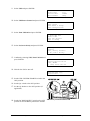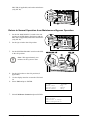
1
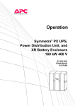
Operation
Symmetra™ PX
48, 96, and 160 kW 400 V
100 kW 208 V
Legal Disclaimer
The information presented in this manual is not warranted by the Schneider Electric IT
Corporation to be authoritative, error free, or complete. This publication is not meant to be a
substitute for a detailed operational and site specific development plan. Therefore, Schneider
Electric IT Corporation assumes no liability for damages, violations of codes, improper
installation, system failures, or any other problems that could arise based on the use of this
Publication.
The information contained in this Publication is provided as is and has been prepared solely
for the purpose of evaluating data center design and construction. This Publication has been
compiled in good faith by Schneider Electric IT Corporation. However, no presentation or
warranty, either express or implied, is made as to the completeness or accuracy of the information
this Publication contains.
IN NO EVENT SHALL SCHNEIDER ELECTRIC IT CORPORATION BE LIABLE
FOR ANY DIRECT, INDIRECT, CONSEQUENTIAL, PUNITIVE, SPECIAL, OR
INCIDENTAL DAMAGES (INCLUDING, WITHOUT LIMITATION, DAMAGES FOR
LOSS OF BUSINESS, CONTRACT, REVENUE, DATA, INFORMATION, OR BUSINESS
INTERRUPTION) RESULTING FROM, ARISING OUT OF, OR IN CONNECTION WITH
THE USE OF, OR INABILITY TO USE THIS PUBLICATION OR THE CONTENT, EVEN
IF SCHNEIDER ELECTRIC IT CORPORATION HAS BEEN EXPRESSLY ADVISED OF
THE POSSIBILITY OF SUCH DAMAGES. SCHNEIDER ELECTRIC IT CORPORATION
RESERVES THE RIGHT TO MAKE CHANGES OR UPDATES WITH RESPECT TO OR
IN THE CONTENT OF THE PUBLICATION OR THE FORMAT THEREOF AT ANY TIME
WITHOUT NOTICE.
Copyright, intellectual, and all other proprietary rights of the content (including but not limited to
software, audio, video, text, and photographs) rests with Schneider Electric IT Corporation or its
licensors. All rights in the content not expressly granted herein are reserved. No rights of any
kind are licensed or assigned or shall otherwise pass to persons accessing this information.
This Publication shall not be for resale in whole or in part.
Table of Contents
About this Manual .......................................................................................................... 1
Companion Manuals ................................................................................................... 1
Find Updates to this Manual ..................................................................................... 1
Overview .............................................................................................................................. 2
User Interface................................................................................................................ 2
Display Interface ........................................................................................................ 3
Operation ............................................................................................................................ 7
Modes..............................................................................................................................
Normal Operation ......................................................................................................
Battery Operation ......................................................................................................
Static Bypass Operation ............................................................................................
Maintenance Bypass Operation (Optional) ................................................................
7
7
7
7
7
Operation Procedures ................................................................................................ 7
Breakers/Switches in the System .............................................................................. 7
Perform a Total Power Off .......................................................................................... 8
Start the System after Total Power Off .......................................................................10
Turn the UPS Load Off ...............................................................................................12
Turn the UPS Load On ...............................................................................................13
Transfer the UPS into Maintenance Bypass Operation ..............................................14
Return to Normal Operation from Maintenance Bypass Operation ............................16
View the Status Screens ............................................................................................19
View the Log Screen ..................................................................................................19
Configuration ....................................................................................................................20
System Settings ...........................................................................................................20
Set Up the Network ....................................................................................................20
Change the Display Interface Settings .......................................................................21
Change the Date and Time .........................................................................................22
Configure Input Contacts ..........................................................................................22
Configure Output Relays ...........................................................................................23
Maintenance ......................................................................................................................24
Life Cycle Monitoring (LCM) .....................................................................................24
Parts Replacement ......................................................................................................24
Determine if you Need a Replacement Part ...............................................................24
Return Parts to Schneider Electric ............................................................................24
Replacement Parts ....................................................................................................26
Replace a Power Management Card ..........................................................................26
Replace a Power Module ...........................................................................................27
Replace a Battery.......................................................................................................28
Replace a Power Distribution Module ........................................................................31
990–3015E-001
Symmetra™ PX48, 96, and 160 kW 400 V 100 kW 208 V Operation
i
Troubleshooting ..............................................................................................................32
Status and Alarm Messages .....................................................................................32
Display Messages ......................................................................................................32
Modular Distribution Fault List ................................................................................36
PDU Fault List ...............................................................................................................37
ii
Symmetra™ PX48, 96, and 160 kW 400 V 100 kW 208 V Operation
990–3015E-001
About this Manual
This manual is for:
• Symmetra PX 48 kW 400 V UPS
• Symmetra PX 96 and 160 kW 400 V UPS and Power Distribution Unit (PDU-XR)
• Symmetra PX 100 kW 208 V UPS and Power Distribution Unit (PDU)
• XR Battery Enclosure
Companion Manuals
For additional information, see the following Symmetra PX manuals:
• Receiving and Unpacking (990-3013)
• Safety (990-2984)
• 96 and 160 kW 400 V Installation (990-3017)
• 48 kW 400 V Installation (990-3151)
• 100 kW 208 V Installation (990-3659)
• 48 kW 400 V XR Battery Enclosure (990-3190)
• Battery Replacement Sheet (990-2958)
Find Updates to this Manual
You can check for updates to this manual on www.apc.com. Look for the latest letter revision (A,
B etc.) of the manual.
990–3015E-001
Symmetra™ PX48, 96, and 160 kW 400 V 100 kW 208 V Operation
1
Overview
User Interface
A
LOAD POWERED LED
When this LED is green, power to the load is on. When the LED is
yellow, the load is supplied through the batteries. When the LED is
flashing yellow, the unit is in bypass.
B
CHECK LOG LED
When this LED is green, a new event has been added to the event
log.
C
WARNING LED
When this LED is yellow, there are one or more warning alarms
in the system.
D
CRITICAL LED
When this LED is red, there are one or more critical alarms in the
system.
E
LCD SCREEN
Displays alarms, status data, instructional help, and configuration
items.
F
UP AND DOWN NAVIGATION
KEYS
Used to scroll through and select menu items.
G
ENTER KEY
Opens menu items and confirms changes to the system parameters.
H
HELP KEY
Opens context-sensitive help.
I
ESC KEY
Returns to the previous screen displayed.
2
Symmetra™ PX48, 96, and 160 kW 400 V 100 kW 208 V Operation
990–3015E-001
Display Interface
Overview Screens
The Overview Screen is the main entrance to the user functions of the display interface. The UP/DOWN
navigation keys take you from one screen to another. When the system is running, the display will scroll
through screens showing information about the system and any active alarms.
Note: The data values shown are for example only.
No Active Alarms
System Date/Time:
28-Mar-2010 10:37:01
Volts In
L1: xxx
L2: xxx
L3: xxx
Out
L1:
L2:
L3:
Amps
xxx
xxx
xxx
Volts Out
L1: xxx
L2: xxx
L3: xxx
kW
xx.x
xx.x
xx.x
kVA
xx.x
xx.x
xx.x
Symmetra PX 160 kW
Runtime: xxhr xxmin
Capacity xxx.x%
UPS Load: xxx%
System Bypass State:
UPS Operation
UPS State:
On Line
Note: Press ENTER to go from any overview screen to the main menu screen.
990–3015E-001
Symmetra™ PX48, 96, and 160 kW 400 V 100 kW 208 V Operation
3
Main Menu Screen
From the main menu it is possible to configure and monitor the system through the sub menu screens:
UPS, Power Dist, Switchgear, Environment, Alarms, Log, Admin, and Help. Use the UP and DOWN
arrow keys to navigate through the menu screens.
Main Screen
4
System Bypass State:
UPS Operation
UPS State:
On Line
Symmetra™ PX48, 96, and 160 kW 400 V 100 kW 208 V Operation
990–3015E-001
Menu Tree
The menu tree provides a quick overview of the functions and views you may access.
UPS Power Control
UPS
UPS Status
UPS Tests & Diags
UPS Configuration
Total Loading
Power Dist
Modular Loading
Volt-Meter
Subfeeds
Switchgear
Status
Factory
Input Contacts
Environment
Output Relays
Alarm Relay Map
Env Monitoring Card
Main Menu Screen
Alarms
All Active Alarms
Active by Severity
Active by Type
Log
View New Log Items
View Entire Log
Clear Entire Log
Network Setup
Admin
Local Interface
Date/Time
Device ID
Manufacturer Data
Factory Defaults
Firmware Upgrade
Life cycle Monitor
Help
990–3015E-001
On any screen
& any line, press ‘?’ for context
sensitive help. Try it now...
Symmetra™ PX48, 96, and 160 kW 400 V 100 kW 208 V Operation
5
Caution: The display provides access to more functions than described in this manual.
Those functions should not be accessed without the assistance of Schneider Electric
Customer Support in order to avoid unwanted load impacts. For Schneider Electric
World-Wide Customer Support, refer to the back cover of this manual. If you by accident go
beyond the functions described, press ESC to return to previous screens.
6
Symmetra™ PX48, 96, and 160 kW 400 V 100 kW 208 V Operation
990–3015E-001
Operation
Modes
In an installation that does not include a maintenance bypass panel, the UPS has three operation modes:
normal operation, battery operation and static bypass operation. If the installation includes a PDU, a
PDU-XR, or an external maintenance bypass panel, the mode maintenance bypass operation also becomes
available.
Normal Operation
During normal operation, the UPS converts the utility/mains supply to conditioned power for the
connected load.
Battery Operation
During battery operation, the UPS provides conditioned power to the connected load from its batteries
for a finite period. The UPS transfers to battery operation if the utility/mains power supply fails or
is outside pre-defined limits.
Static Bypass Operation
Static bypass operation is a feature that keeps the load supplied directly from the utility/mains supply
during different scenarios on the UPS or downstream from the UPS. In static bypass operation, the
utility/mains is supplying power to the connected load directly, bypassing all internal UPS functions.
Maintenance Bypass Operation (Optional)
The UPS can be connected to a PDU, a PDU-XR, or an optional external maintenance bypass panel
that enables the user to bypass the UPS completely for maintenance purposes that might even include
replacement of the entire UPS. The connected load will then be fed directly from the utility/mains supply,
and there will in this case be no filtering of the supply or battery backup of the load.
Operation Procedures
Breakers/Switches in the System
Q1
UPS input
Q2
UPS output
Q3
Maintenance Bypass
Q5
Static Bypass input (only in dual utility/mains systems)
Note: If the system does not contain a PDU or PDU-XR, the Q1, Q2, and Q3 switches and
the Q5 breaker should be located in an optional external maintenance bypass panel. See the
documentation included with the maintenance bypass panel for additional information.
990–3015E-001
Symmetra™ PX48, 96, and 160 kW 400 V 100 kW 208 V Operation
7
Perform a Total Power Off
WARNING: This procedure will disconnect the load.
Note: If shutdown via the display is disabled, then you cannot perform this procedure and
the message: Command not allowed, UPS configured to never shutdown appears. If
you want to enable shutdown via the display, this is done by a Field Service Engineer via
the UPSTuner.
1. Select UPS and press ENTER.
→ UPS
Alarm
Power Dist Log
Switch Gear Admin
Environment Help
2. Select UPS Power Control and press ENTER.
→ UPS Power Control
UPS Status
UPS Tests & Diags
UPS Configuration
3. Select Turn UPS Off and press ENTER.
→ Turn UPS Off
Reboot UPS
UPS into Bypass
UPS to Sleep
4. Select No, Don’t Notify to shut down without
delay and press ENTER.
Note: This action will cut all power
to the load without shutting it down
first. If you want to shut down the
servers first, then choose Yes, Notify
Servers. Note that this function
is only available for servers with
PowerChute.
Notify PowerChute ?
Cancel
Yes, Notify Servers
→ No, Don't Notify
5. Confirm YES, Turn UPS Off and press
ENTER.
Turn UPS off
Without Server
Notification?
> NO, ABORT
→> YES, Turn UPS Off
6. Wait for the UPS to turn off.
Turning UPS off,
please wait...
8
Symmetra™ PX48, 96, and 160 kW 400 V 100 kW 208 V Operation
990–3015E-001
7. Set the UPS SYSTEM ENABLE switch to the
OFF position.
7
8. Set the Q2 switch to the OFF position.
9. Set the Q1 switch to the OFF position.
10. Set the Q5 breaker to the OFF position (if
applicable).
11. Verify that the maintenance bypass switch
(Q3) is in the OFF position.
12. Set the DC DISCONNECT switch on all of
XR Battery Enclosures/PDU-XR
the XR Battery Enclosures and the PDU-XR
(if applicable) and on the main frame (only for
PX48) to the OFF position.
13. Disconnect all battery units by removing them
or pulling them out to the red disconnect line.
Caution: To ensure that the
enclosure does not tip, do not pull
out the battery units beyond the red
disconnect line. If you intend to
completely remove the battery units,
remove them from the enclosure one
at a time. Failure to pull battery units
out to the red disconnect line could
cause deep discharge/damage to the
batteries.
14. Set the upstream mains power to the OFF or
LOCKED OUT position. If the UPS has a dual
mains supply, set both supplies to the OFF or
LOCKED OUT position.
15. Measure bypass/output DC and mains to
ensure that the system is completely powered
off.
990–3015E-001
Symmetra™ PX48, 96, and 160 kW 400 V 100 kW 208 V Operation
9
Start the System after Total Power Off
1. Set the upstream utility/mains power to the
XR Battery Enclosures/PDU-XR
ON or LOCKED IN position. If the UPS has a
dual mains supply, set both supplies to the ON
or LOCKED IN position.
2. Set the DC DISCONNECT switch to the ON
position on all XR Battery Enclosures and the
PDU-XR (if applicable) and on the main frame
(only PX 48).
3. Set the Q1 switch to the ON position.
4. Set the SYSTEM ENABLE switch on the UPS
to the ON position.
4
Note: Wait approximately two
minutes for the system to start.
5. Set the Q5 breaker to the ON position (if
applicable).
Note: The H2 LED next to the Q2
switch will turn on, indicating that it
is safe to operate the Q2 switch.
6. Set the Q2 switch on the PDU, PDU-XR or
the external maintenance bypass panel to the
ON position.
7. Select UPS and press ENTER.
→ UPS
Power Dist
Switch Gear
Environment
Alarms
Log
Admin
Help
8. Select UPS Power Control and press ENTER.
→ UPS Power Control
UPS Status
UPS Tests & Diags
UPS Configuration
9. Select Turn UPS On and press ENTER.
→ Turn UPS On
UPS On Into Bypass
10
Symmetra™ PX48, 96, and 160 kW 400 V 100 kW 208 V Operation
990–3015E-001
10. Confirm by selecting Yes, Turn UPS On and
press ENTER.
Confirm:
Turn UPS On ?
>NO, ABORT
→ >Yes, Turn UPS On
11. Wait for the UPS to turn on.
Turning UPS on,
Please wait...
990–3015E-001
Symmetra™ PX48, 96, and 160 kW 400 V 100 kW 208 V Operation
11
Turn the UPS Load Off
1. Select UPS and press ENTER.
→ UPS
Power Dist
Switch Gear
Environment
Alarms
Log
Admin
Help
2. Select UPS Power Control and press ENTER.
→ UPS Power Control
UPS Status
UPS Tests & Diags
UPS Configuration
3. Select Turn UPS Off and press ENTER.
→ Turn UPS Off
Reboot UPS
UPS Into Bypass
UPS To Sleep
4. Select No, Don’t Notify and press ENTER.
Note: This action will cut all power
to the load without shutting it off
first. If you want to shut down the
servers first, then choose Yes, Notify
Servers.Note that this function
is only available for servers with
PowerChute.
Notify PowerChute?
Cancel
Yes, Notify Servers
→ No, Don't Notify
5. Confirm YES, Turn UPS Off and press
ENTER.
Turn UPS Off Without
Server Notification?
>NO, ABORT
→ YES, Turn UPS Off
6. Wait for the UPS to turn off.
Turning UPS off,
please wait...
12
Symmetra™ PX48, 96, and 160 kW 400 V 100 kW 208 V Operation
990–3015E-001
Turn the UPS Load On
1. Select UPS and press ENTER.
→ UPS
Power Dist
Switch Gear
Environment
Alarms
Log
Admin
Help
Press
2. Select UPS Power Control and press ENTER.
→ UPS Power Control
UPS Status
UPS Tests & Diags
UPS Configuration
Press
3. Select Turn UPS On and press ENTER.
→ Turn UPS On
UPS On Into Bypass
Press
4. Confirm by selecting Yes, Turn UPS On and
press ENTER.
Confirm:
Turn UPS On?
>NO, ABORT
→ >YES, Turn UPS On
Press
5. Wait for the UPS to turn the load on.
Turning UPS on,
please wait...
990–3015E-001
Symmetra™ PX48, 96, and 160 kW 400 V 100 kW 208 V Operation
13
Transfer the UPS into Maintenance Bypass Operation
Note: If shutdown via the display is disabled, then you cannot perform this procedure and
the message: Command not allowed, UPS configured to never shutdown appears. If
you want to enable shutdown via the display, this is done by an Field Service Engineer
via the UPSTuner.
1. Select UPS and press ENTER.
→ UPS
Power Dist
Switch Gear
Environment
Alarms
Log
Admin
Help
2. Select UPS Power Control and press ENTER.
→ UPS Power Control
UPS Status
UPS Tests & Diags
UPS Configuration
3. Select UPS into Bypass and press ENTER.
Turn UPS Off
Reboot UPS
→ UPS into Bypass
UPS to Sleep
4. Select Yes, Into Bypass and press ENTER.
Confirm:
UPS into Bypass?
NO, ABORT
→ YES, Into Bypass
5. Wait for the transfer to complete.
Putting UPS into
Bypass, please
wait....
6. Confirm that the transfer to bypass is complete.
Note: The H3 LED next to the Q3
switch will turn on, indicating that it
is ok to operate the Q3 switch.
UPS is now in
Bypass.
Press any key....
7. Set the Q3 switch to the ON position.
Note: The H2 LED beside the Q2
switch will turn on, indicating that it
is ok to operate the Q2 switch.
8. Set the Q2 switch to the OFF position.
14
Symmetra™ PX48, 96, and 160 kW 400 V 100 kW 208 V Operation
990–3015E-001
9. Select UPS and press ENTER.
→ UPS
Power Dist
Switch Gear
Environment
Alarms
Log
Admin
Help
10. Select UPS Power Control and press ENTER.
→ UPS Power Control
UPS Status
UPS Tests & Diags
UPS Configuration
11. Select Turn UPS Off and press ENTER.
→ Turn UPS Off
Reboot UPS
UPS into Bypass
UPS to Sleep
12. Select No, Don’t Notify and press ENTER.
Notify PowerChute ?
Cancel
Yes, Notify Servers
→ No, Don't Notify
13. Confirm by selecting YES, Turn UPS Off and
press ENTER.
Turn UPS Off Without
Server Notification?
>NO, ABORT
→ >YES, Turn UPS Off
14. Wait for the UPS to turn off.
Turning UPS off,
please wait....
15. Set the UPS SYSTEM ENABLE switch to the
OFF position.
15
16. Set the Q1 switch to the OFF position.
17. Set the Q5 breaker to the OFF position (if
applicable).
18. Set the DC DISCONNECT switch to the OFF
XR Battery Enclosures/PDU-XR
position on all XR Battery Enclosures and the
990–3015E-001
Symmetra™ PX48, 96, and 160 kW 400 V 100 kW 208 V Operation
15
PDU XR (if applicable) and on the main frame
(only PX 48).
Return to Normal Operation from Maintenance Bypass Operation
1. Set the DC DISCONNECT switch to the ON
position on all XR Battery Enclosures and the
PDU-XR (if applicable) and on the main frame
(only PX 48).
2. Set the Q1 switch to the ON position.
3. Set the SYSTEM ENABLE switch on the UPS
to the ON position.
4
Note: Wait approximately two
minutes for the system to start.
4. Set the Q5 breaker to the ON position (if
applicable).
5. Use the display interface to turn the UPS load
on.
6. Select UPS and press ENTER.
→ UPS
Power Dist
Switch Gear
Environment
Alarms
Log
Admin
Help
7. Select UPS Power Control and press ENTER.
→ UPS Power Control
UPS Status
UPS Tests & Diags
UPS Configuration
16
Symmetra™ PX48, 96, and 160 kW 400 V 100 kW 208 V Operation
990–3015E-001
8. Select Turn UPS On into Bypass and press
ENTER.
Turn UPS On
→ UPS On into Bypass
9. Select Continue Turn On and press ENTER.
Battery back-up not
available in bypass!
>Cancel
→ >Continue Turn On
10. Confirm by selecting Yes, On Into Bypass
and press ENTER.
Confirm:
UPS on Into Bypass
>NO, ABORT
→ >Yes, On Into Bypass
11. Wait for the UPS to turn the load on.
Turning UPS on Into
Bypass.
Please wait...
12. The UPS is now ON.
Note: The H2 LED next to the Q2
switch will turn on, indicating that it
is safe to operate the Q2 switch.
UPS’s output is now
in bypass
Press any key...
13. Set the Q2 switch on the PDU, PDU-XR or
the external maintenance bypass panel to the
ON position.
Note: The H3 LED next to the Q3
switch will turn on, indicating that it
is safe to operate the Q3 switch.
14. Set the Q3 switch to the OFF position.
15. Use the display interface to transfer the UPS
out of bypass:
16. Select UPS and press ENTER.
→ UPS
Power Dist
Switch Gear
Environment
Alarms
Log
Admin
Help
17. Select UPS Power Control and press ENTER.
→ UPS Power Control
UPS Status
UPS Tests & Diags
UPS Configuration
990–3015E-001
Symmetra™ PX48, 96, and 160 kW 400 V 100 kW 208 V Operation
17
18. Select UPS out of Bypass and press ENTER.
Turn UPS Off
Reboot UPS
→ UPS out of Bypass
UPS to Sleep
19. Confirm by selecting Yes, Out of Bypass and
press ENTER.
Confirm:
UPS out of Bypass?
>NO, ABORT
→ >YES, Out of Bypass
20. Wait for the UPS to transfer out of bypass.
Putting UPS out of
Bypass, please
wait....
21. The UPS is now out of bypass and is in normal
operation.
18
UPS is now out of
bypass
Press any key....
Symmetra™ PX48, 96, and 160 kW 400 V 100 kW 208 V Operation
990–3015E-001
View the Status Screens
1. Select UPS and press ENTER.
→ UPS
Power Dist
Switch Gear
Environment
Alarms
Log
Admin
Help
2. Select UPS Status and press ENTER.
UPS Power Control
→ UPS Status
UPS Tests & Diags
UPS Configuration
3. Use the UP and DOWN arrow keys to navigate
through the Status screens.
Symmetra PX 160 kW
Status: On Line
No UPS Alarms
View the Log Screen
1. Select Log and press ENTER.
UPS
Power Dist
Switch Gear
Environment
Alarms
→Log
Admin
Help
2. Select View New Log Items to see new log
items when the Check Log LED is lit and press
ENTER. To see historical events select the
View Entire Log and press ENTER.
→ View New Log Items
View Entire Log
Clear Entire Log
3. Use the UP and DOWN arrow keys to navigate
through the Log screens.
990–3015E-001
Log Item ≥ 1 of 2
03/14/07 10:37:02
<Description>
Symmetra™ PX48, 96, and 160 kW 400 V 100 kW 208 V Operation
19
Configuration
System Settings
Set Up the Network
1. Select Admin and press ENTER.
UPS
Power Dist
Switch Gear
Environment
Alarms
Log
→ Admin
Help
2. Select Network Setup and press ENTER.
→ Network Setup
Local Interface
Date/Time
Device ID
3. Select Mode and press ENTER.
Stat:
→ Mode:
IP:
SM:
4. Select Fixed IP Addr to give a specific IP
address to the UPS system or select one of the
other three methods to obtain an IP address. In
this example Fixed IP Addr mode is selected.
→ Fixed IP Addr
DHCP Only
BOOTP Only
DHCP & BOOTP
5. Select IP (Internet Protocol), SM (Subnet
Mask), and GW (GateWay) and change the
settings using the UP and DOWN arrow keys.
Press ENTER to confirm the changes.
20
→
→
→
IP:
SM:
GW:
Symmetra™ PX48, 96, and 160 kW 400 V 100 kW 208 V Operation
990–3015E-001
Change the Display Interface Settings
1. Select Admin and press ENTER.
UPS
Power Dist
Switch Gear
Environment
Alarms
Log
→ Admin
Help
2. Select Local Interface and press ENTER.
Network Setup
→ Local Interface
Date/Time
Device ID
3. Select Display Behavior and press ENTER.
Local Password
→ Display Behaviour
Alarm Beeper
4. Select Contrast, Key Click, Beeper Volume,
or Check Log Light and change the settings
using the UP and DOWN arrow keys. Press
ENTER to save the changes.
990–3015E-001
→ Contrast ≥ 4
Key Click ≥ On
Beeper Volume > High
Check Log Light
Symmetra™ PX48, 96, and 160 kW 400 V 100 kW 208 V Operation
21
Change the Date and Time
1. Select Admin and press ENTER.
UPS
Power Dist
Switch Gear
Environment
Alarms
Log
→ Admin
Help
2. Select Date/Time and press ENTER.
Network Setup
Local Interface
→ Date/Time
Device ID
3. Select Date or Time and change the settings
by using the UP and DOWN arrow keys. Press
ENTER to save the changes.
Mode: Manual
Format: mm/dd/yyyy
Date: xx/xx/xxxx
Time: xx:xx:xx
Configure Input Contacts
1. Select Environment and press ENTER.
UPS
Power Dist
Switch Gear
→ Environment
Alarms
Log
Admin
Help
2. Select Input Contacts and press ENTER.
→ Input Contacts
Output Relays
Alarm Relay Map
3. Select desired output relay, 1 through 4, select
Configuration, and press ENTER.
Input Contact:xof4
<contact name>
Status: Normal
→ Configuration
4. Change the settings for name/location, alarms,
severity, and normal state.
22
Name/Location x
Alarms: Enabled
Severity: Critical
Normal: Open
Symmetra™ PX48, 96, and 160 kW 400 V 100 kW 208 V Operation
990–3015E-001
Configure Output Relays
1. Select Environment and press ENTER.
UPS
Power Dist
Switch Gear
→ Environment
Alarms
Log
Admin
Help
2. Select Output Relays and press ENTER.
Input Contacts
→ Output Relays
Alarm Relay Map
3. Select desired output relay, 1 through 4, select
Configuration, and press ENTER.
Input Contact:xof4
<relay name>
Status: Closed
→ Configuration
4. Change the settings for name and normal
position for the selected output relay.
990–3015E-001
Relay x Name
<output relay>
Normal: Closed
Symmetra™ PX48, 96, and 160 kW 400 V 100 kW 208 V Operation
23
Maintenance
Life Cycle Monitoring (LCM)
The Life Cycle Monitoring (LCM) function provides UPS maintenance advice to guarantee installation
availability for the user.
The display gives three messages enabling the following to be identified.
Display Message
Status
Contact APC for secure start-up
Start-up check is recommended – Please call the
APC by Schneider Electric support center
Warranty expiring soon
The end of the contractual legal warranty - Please
call the APC by Schneider Electric support center
Technical check recommended
Regular maintenance requirements and the end of
service life consumable components - Please call
the APC by Schneider Electric support center
In addition to these messages, the warning LED lights up and the buzzer sounds. These messages can be
disabled by choosing Admin > Life Cycle Monitor > Settings > Yes. This will cause the warning LED to
go out, the buzzer to stop and remove any Life Cycle Monitoring messages.
Parts Replacement
Determine if you Need a Replacement Part
To determine if you need a replacement part, contact Schneider Electric Customer Support and follow the
procedure below so that the Schneider Electric Customer Support representative can assist you promptly:
1. In the event of a module failure, the display interface may show additional “fault list” screens.
Press any key to scroll through these fault lists, record the information, and provide it to the
representative.
2. Write down the serial number of the unit so that you will have it easily accessible when you
contact Schneider Electric Customer Support.
3. If possible, call Schneider Electric Customer Support from a telephone that is within reach of the
UPS display interface so that you can gather and report additional information to the representative.
4. Be prepared to provide a detailed description of the problem. A representative will help you
solve the problem over the telephone, if possible, or will assign a Return Material Authorization
(RMA) number to you. If a module is returned to Schneider Electric, this RMA number must be
clearly printed on the outside of the package.
5. If the unit is within the warranty period, repairs or replacements will be performed free of charge.
If it is not within the warranty period, there will be a charge.
6. If the unit is covered by an Schneider Electric service contract, have the contract available to
provide information to the representative.
Return Parts to Schneider Electric
Call Schneider Electric Customer Support to obtain an RMA number.
24
Symmetra™ PX48, 96, and 160 kW 400 V 100 kW 208 V Operation
990–3015E-001
To return a failed module to Schneider Electric, pack the module in the original shipping materials, and
return it by insured, prepaid carrier. The Schneider Electric Customer Support representative will provide
the destination address. If you no longer have the original shipping materials, ask the representative about
obtaining a new set. Pack the module properly to avoid damage in transit. Never use styrofoam beads or
other loose packaging materials when shipping a module, as the module may settle in transit and
become damaged. Enclose a letter in the package with your name, RMA number, address, a copy of the
sales receipt, description of the problem, a phone number, and a check as payment (if necessary).
Note: Damages sustained in transit are not covered under warranty.
990–3015E-001
Symmetra™ PX48, 96, and 160 kW 400 V 100 kW 208 V Operation
25
Replacement Parts
WARNING: All safety instructions in the Safety sheet (990-2984) should be read,
understood, and followed prior to handling the system. Failure to do so could result in
equipment damage, serious injury, or death.
WARNING: Only trained persons familiar with the construction and operation of
the equipment, as well as the electrical and mechanical hazards involved, may install
and remove system components.
Note: A maximum of two SmartSlots can be used.
Part
Part number
16 kW power module for 48, 96 and 160 kW 400 V
SYPM10K16H
10 kW power module for 100 kW 208V, High Efficiency
SYPM10KF2
Battery module (four battery units)
SYBT9-B4
Battery unit
SYBTU2-PLP
SmartSlot relay I/O module (option)
AP9610
Modbus/Jbus interface Card (option)
AP9622
Network Management Card (option)
Go to www.apc.com for a list of Network Management
Cards
Power distribution module
Go to www.apc.com for a complete list of breaker
Replace a Power Management Card
A: Only the cards in these two locations can be replaced.
1. Loosen the two Phillips screws on the sides of the card and carefully pull it out of the enclosure.
2. Install the new card and secure it with the two screws.
Note: The Symmetra PX 100 kW has an embedded NMC. The SmartSlots do not support
an additional NMC.
26
Symmetra™ PX48, 96, and 160 kW 400 V 100 kW 208 V Operation
990–3015E-001
Replace a Power Module
WARNING: Before removing any power modules, make sure that the remaining power
modules can support the load.
WARNING: Two people are needed to lift components weighing between 18–32 kg
(40–70 lbs).
1. Turn the locking latch until the arrow points downwards.
2. Unscrew the spring-activated knobs on both sides of the module.
3. Pull the module up and out of the enclosure as far as the lock mechanism will allow.
4. Release the lock by pressing the black plastic tab on both sides of the module.
5. Pull the module out of the enclosure.
6. Push the replacement module securely into the enclosure.
Caution: Do not attempt to insert the power module using excessive force, but make sure
that it is in place before continuing.
7. Tighten the spring-activated knobs on both sides of the module to ensure proper contact.
8. Secure the locking latch to start the power module.
Caution: Tighten the spring-activated knobs before securing the locking latch to ensure
that the module makes proper contact within the unit. The power module will not operate
unless the locking latch is engaged. If it has not engaged, take out the power module and
insert it again.
990–3015E-001
Symmetra™ PX48, 96, and 160 kW 400 V 100 kW 208 V Operation
27
Replace a Battery
WARNING: Servicing of batteries should be performed or supervised by personnel
knowledgeable about batteries and the required precautions.
Caution: When replacing batteries, replace with same type and number of batteries or
battery packs.
Caution: Risk of explosion if battery is replaced by an incorrect type. Dispose of the
batteries according to the instructions.
Caution: Do not dispose of batteries in a fire. The batteries may explode.
Caution: Do not open or mutilate batteries. Released electrolyte is harmful to the skin
and eyes. It may be toxic.
Caution: A battery can present a risk of electrical shock and high short circuit current. The
following precautions should be observed when working on batteries:
A. Remove watches, rings, or other metal objects
B. Use tools with insulated handles
C. Wear rubber gloves and boots
D. Do not lay tools or metal parts on top of batteries
E. Disconnect charging source prior to connecting or disconnecting battery terminals
Note: The batteries must only be replaced with model “High performance battery unit”.
Caution: Wait until the UPS system is ready to be powered up before installing battery
modules in the UPS. Installing the batteries more than 72 hours or 3 days before the UPS is
powered up can result in a deep discharge of the batteries and cause permanent damage.
28
Symmetra™ PX48, 96, and 160 kW 400 V 100 kW 208 V Operation
990–3015E-001
Storage of the battery modules:
The battery modules must be stored indoors and with their protective packaging still in place.
Ambient temperature: -15 to 40 °C
(5 to 104 °F)
Relative humidity: 25–85%
Non-condensing
Store in a place free from: vibration,
dust, direct sunlight, and moisture
Stored batteries must be recharged at regular intervals depending on the storage temperature:
Storage temperature
Recharge interval
-15 to 20 °C (5 to 68°F)
9 months
20 to 30 °C (68 to 86°F)
6 months
30 to 40 °C (86 to 104 °F)
3 months
Caution: Do not store the batteries for more than 12 months.
Caution: Two persons are needed for lifting components weighing 18–32 kg (40–70 lb).
1. Holding the handle, gently lift the battery unit and pull it halfway out. A locking mechanism
prevents the battery unit from being pulled all the way out.
2. Release the locking mechanism by lifting the battery unit. Pull the battery unit completely out
while supporting it.
3. Take the replacement battery unit and push it into the system.
990–3015E-001
Symmetra™ PX48, 96, and 160 kW 400 V 100 kW 208 V Operation
29
Note: When replacing batteries, always replace both batteries A+B or C+D (see illustration
above) as they are interconnected in pairs.
For four batteries in a row it is recommended to replace all four at the same time to ensure
optimal run-time (Example 1). The batteries can also be replaced in twos, but always A+B
(Example 2) or C+D (Example 3).
For two batteries in a row, always replace both batteries at the same time (Example 4).
Four batteries in a row
Column A
Column B
Column C
Column D
Example 1 –
Recommended
New
New
New
New
Example 2
– Minimum
requirement
New
New
Old
Old
Example 3
– Minimum
requirement
Old
Old
New
New
Two batteries in a row
Example 4
— Minimum
requirement
Column A
Column B
New
New
Note: Allow batteries a 24-hour recharging period after system start-up/battery replacement
for battery monitoring data to become fully reliable.
30
Symmetra™ PX48, 96, and 160 kW 400 V 100 kW 208 V Operation
990–3015E-001
Replace a Power Distribution Module
Note: The load that is connected to the actual power distribution module will not be
supported when the locking latch on the module is opened.
1. Switch the breakers to the OFF position.
2. Disconnect the power cable from the power distribution module’s extension cable or Rack-Mount
PDU.
3. Open the locking latch on the module and gently pull the module out of the enclosure.
4. Take the replacement power distribution module and open the locking latch. Route the power
cable through the top of the enclosure and slide the power distribution module into place.
5. Secure the latch to lock the module.
6. Switch the breakers to the ON position.
990–3015E-001
Symmetra™ PX48, 96, and 160 kW 400 V 100 kW 208 V Operation
31
Troubleshooting
WARNING: Only trained persons familiar with the construction and operation of
the equipment, as well as the electrical and mechanical hazards involved, may install
and remove system components.
Status and Alarm Messages
This section lists the status and alarm messages that the UPS might display. The messages are listed
in alphabetical order, and a suggested corrective action is listed with each alarm message to help you
troubleshoot problems.
Note: Contact Schneider Electric Customer Support if you see alarm or status messages that
are not listed here.
Note: If a problem is reported, ensure that the system component in question is correctly
installed.
Display Messages
Display Message
Meaning
Corrective Action
Battery Charger Fault
The battery charger is not
functioning properly.
Contact Schneider Electric Customer
Support (see the back cover).
Battery Defective
The battery capacity is estimated to
be below 50% of the expected.
Replace battery. See “Replace a
Battery“.
Battery Fault
A battery module has failed and
requires replacement.
Replace battery. See “Replace a
Battery“.
Battery High Temperature Violation
The temperature of one or more
battery units has exceeded system
specifications.
Ensure that the ambient temperature
meets the specifications of the
system. If the ambient temperature
is below 40 °C (104 °F), then initiate
a self-test to detect any bad battery
units. Replace any bad battery units.
Battery High Voltage Violation
The battery voltage is too high and
the charger has been deactivated.
Contact Schneider Electric Customer
Support (see the back cover).
Battery Monitor Card Fault
The battery monitor card has failed.
Contact Schneider Electric Customer
Support (see the back cover).
Battery Monitor Card Removed
The battery monitor card has been
removed.
Contact Schneider Electric Customer
Support (see the back cover).
Battery Weak
The battery capacity is estimated to
be below 75% of the expected.
Replace battery. See “Replace a
Battery“.
Contact APC for secure start-up
The UPS has been running 5 days.
start-up check by an Schneider
Electric Field Service Engineer
(FSE) is recommended.
Contact Schneider Electric Customer
Support (see the back cover).
Discharged Battery
The UPS is online and the battery
charge is low.
No corrective action necessary.
Note: If the input voltage fails,
runtime will be limited.
32
Symmetra™ PX48, 96, and 160 kW 400 V 100 kW 208 V Operation
990–3015E-001
Display Message
Meaning
Corrective Action
Extended Run Frame Fault
One of the battery enclosures has
failed.
Contact Schneider Electric Customer
Support (see the back cover).
External DC Disconnect Switch
Open
The external DC DISCONNECT
switch tripped. Battery power is not
available or the runtime is lower
than expected.
Close the external DC
DISCONNECT switch. If the
problem continues, call Schneider
ElectricCustomer Support.
External Switch Gear
Communication Card Fault
The external switch gear
communication card has failed.
Contact Schneider Electric Customer
Support (see the back cover).
External Switch Gear
Communication Card Removed
The system no longer detects an
external switch gear communication
card.
Option 1: Ensure the external
switch gear communication card is
installed properly.
Option 2: Contact Schneider
Electric Customer Support (see the
back cover).
Graceful Shutdown Initiated
A graceful shutdown or reboot
has been initiated from the display
interface or other accessory.
No corrective action necessary.
Internal Communication Bus Fault
One of the buses used for
communication between the
UPS modules has failed.
Contact Schneider Electric Customer
Support (see the back cover).
In Bypass: Hardware Fault
The system has transferred into
bypass because a fault has occurred.
Contact Schneider Electric Customer
Support (see the back cover).
In Bypass: Overload
The system has transferred into
bypass because the load has
exceeded the power capacity of the
system.
Option 1: Decrease the load.
Option 2: Add a power module to
the system.
In Bypass: User-Initiated
The system has been transferred into
bypass due to user action.
Check for any problems with the
system.
Transfer the system to normal
operation.
Input Voltage or Frequency Cannot
Support Bypass
The frequency or voltage is out
of acceptable range for bypass.
This message occurs when the
UPS is online, and indicates that
bypass mode may not be available
if required.
Correct the input voltage to provide
acceptable voltage or frequency.
Intelligence Module Fault
The main intelligence module has
failed and requires replacement.
Contact Schneider Electric Customer
Support (see the back cover).
Load (kVA) Alarm Violation
The load has exceeded the user
specified load alarm threshold.
Option 1: Use the display interface
to raise the alarm threshold.
Option 2: Reduce the load.
Local Management-To-UPS
Communication Lost
Internal communications in the
system have failed.
Contact Schneider Electric Customer
Support (see the back cover).
Low Battery
The UPS is in battery operation and
the battery charge is low.
Runtime is limited. Shut down the
system and the load equipment or
restore the input voltage.
No Batteries Detected
No battery power is available.
Option 1: Ensure the batteries are
installed properly.
Option 2: Check to see whether the
DC Breaker has been tripped.
Option 3: Contact Schneider
Electric Customer Support (see the
back cover).
990–3015E-001
Symmetra™ PX48, 96, and 160 kW 400 V 100 kW 208 V Operation
33
Display Message
Meaning
Corrective Action
No Power Modules Detected
No power modules are available.
Option 1: Ensure that the power
modules are properly installed, the
two fastening screws are tight, and
the locking latch is engaged.
Option 2: Check for other
communication alarm messages in
the log.
Not Synchronized Fault
System cannot synchronize to AC
line and bypass mode may not be
available.
Option 1: Decrease the sensitivity
to input frequency.
Option 2: Correct the input
voltage to provide acceptable
voltage/frequency.
Output Voltage Not In Range
The output voltage is not within the
specified range.
Evaluate the threshold setting.
If necessary, adjust it for your
situation. Contact Schneider Electric
Customer Support (see the back
cover).
Overload
The load has exceeded the system
power capacity.
Option 1: Decrease the load.
Option 2: Add a power module to
the system.
Power Failure
The input voltage is not acceptable
for normal operation.
Contact Schneider Electric Customer
Support (see the back cover).
Power Module Fault
A power module has failed and
requires replacement.
Replace power module. See
“Replace a Power Module“.
Redundancy Alarm
Actual power module redundancy
has fallen below user-specified
redundancy alarm threshold. At
least one power module has failed,
or the load has increased.
Option 1: If possible, install
additional power modules. See
“Replace a Power Module“.
Option 2: Replace failed modules.
See “Replace a Power Module“.
Option 3: Reduce the load.
Option 4: Change alarm limit.
Redundancy Lost
The UPS no longer detects redundant
power modules. One or more power
modules have failed, or the load has
increased.
Option 1: If possible, install
additional power modules. See
“Replace a Power Module“.
Option 2: Replace failed modules.
See “Replace a Power Module“.
Option 3: Reduce the load.
Option 4: Change alarm limit.
Redundant Intelligence Module
Fault
The redundant intelligence module
has failed and requires replacement.
Contact Schneider Electric Customer
Support (see the back cover).
Redundant Intelligence Module in
Control
The main intelligence module has
failed, and the redundant intelligence
module is functioning as the primary
intelligence module.
Contact Schneider Electric Customer
Support (see the back cover).
Replacement Battery Needed
One or more battery units needs to
be replaced.
Replace battery unit(s). See
“Replace a Battery“.
Runtime Alarm
The predicted runtime is lower than
the user-specified minimum runtime
alarm threshold. At least one battery
module has failed or the load has
increased.
Option 1: Install additional battery
modules. See “Replace a Battery“
Option 2: Replace failed battery
modules. See “Replace a Battery“
Option 3: Reduce the load.
Option 4: Change alarm limit.
Site Wiring Fault
There is a problem with the phase
rotation or a phase is missing in the
input voltage to the UPS.
Contact the certified electrician that
installed the system.
Static Bypass Switch Module Fault
The static bypass switch module has
failed and requires replacement.
Contact Schneider Electric Customer
Support (see the back cover).
34
Symmetra™ PX48, 96, and 160 kW 400 V 100 kW 208 V Operation
990–3015E-001
Display Message
Meaning
Corrective Action
Static Bypass Switch Module
Removed
The system no longer detects a static
bypass switch module.
Option 1: Ensure that the static
bypass switch module is installed
properly.
Option 2: Call Schneider Electric
Customer Support for replacement
of the static bypass switch module.
System in Maintenance Bypass
The system is in maintenance
bypass: the Q2 breaker is open and
the Q3 breaker is closed.
No corrective action necessary.
System Power Supply Card Fault
The system power supply card has
failed and requires replacement.
Ensure that the power supply card is
installed properly. See “Replace a
Power Management Card“.
System Start-Up Configuration Fault
The system configuration download
has failed. Unable to determine the
system voltage or frame size.
Check for other alarms and contact
Schneider Electric Customer
Support (see the back cover).
Technical check recommended
Regular maintenance requirements
and the end of service life
consumable components.
Contact Schneider Electric Customer
Support (see the back cover).
Warranty expiring soon
The end of the contractual legal
warranty.
Contact Schneider Electric Customer
Support (see the back cover).
990–3015E-001
Symmetra™ PX48, 96, and 160 kW 400 V 100 kW 208 V Operation
35
Modular Distribution Fault List
The display interface will identify the number of the power distribution modules that has caused an
alarm or warning.
Display Message
Meaning
Corrective Action
High Module Current Alarm
The threshold of the high module
current has been exceeded.
Evaluate the threshold setting. If
necessary, adjust it for your situation.
High Subfeed Current Alarm
The threshold of the high subfeed
current has been exceeded.
Evaluate the threshold setting. If
necessary, adjust it for your situation.
Low Module Current Alarm
The threshold of the low module
current has been exceeded.
Evaluate the threshold setting. If
necessary, adjust it for your situation.
Low Subfeed Current Alarm
The threshold of the low subfeed
current has been exceeded.
Evaluate the threshold setting. If
necessary, adjust it for your situation.
Max Module Current Alarm
The threshold of the maximum
module current has been exceeded.
Evaluate the threshold setting. If
necessary, adjust it for your situation.
Max Subfeed Current Alarm
The threshold of the maximum
subfeed current has been exceeded.
Evaluate the threshold setting. If
necessary, adjust it for your situation.
Min Module Current Alarm
The threshold of the minimum
module current has been exceeded.
Evaluate the threshold setting. If
necessary, adjust it for your situation.
Min Subfeed Current Alarm
The threshold of the minimum
subfeed current has been exceeded.
Evaluate the threshold setting. If
necessary, adjust it for your situation.
Communication Lost With Metering
Board Alarm
Communication has been lost with
the power distribution module.
Check the communication cables
to ensure that they are properly
connected. Contact Schneider
Electric Customer Support (see the
back cover).
Module Breaker Open Alarm
A modular circuit breaker is open.
Check the modular circuit breakers
to see if one has been over-loaded.
Replace if necessary.
Subfeed Breaker Open Alarm
A subfeed circuit breaker is open.
Check the subfeed circuit breakers
to see if one has been over-loaded.
36
Symmetra™ PX48, 96, and 160 kW 400 V 100 kW 208 V Operation
990–3015E-001
PDU Fault List
Display Message
Meaning
Corrective Action
System In Maintenance Bypass
The system is in maintenance
bypass: the Q2 switch is open and
the Q3 switch is closed.
No corrective action necessary.
Min Output Voltage Alarm
Phase-to-neutral output voltage for
phase <L-N> has dropped below the
configured limit.
Evaluate the threshold setting. If
necessary, adjust it for your situation.
Max Output Voltage Alarm
Phase-to-neutral output voltage
for phase <L-N> exceeded the
configured limit.
Evaluate the threshold setting. If
necessary, adjust it for your situation.
Max Total Output Current Alarm
Current of output phase <n>
exceeded the configured limit.
Evaluate the threshold setting. If
necessary, adjust it for your situation.
Min Total Output Current Alarm
Current of output phase <n> dropped
below the configured limit.
Evaluate the threshold setting. If
necessary, adjust it for your situation.
Output Frequency Alarm
Frequency of the output current is
above or below the range that is
configured as acceptable.
Evaluate the threshold setting. If
necessary, adjust it for your situation.
Critical Input Contact Fault
A user-configured contact connected
to the system is reporting an alarm
condition.
Determine why the alarm has
occurred. This is a user-specific
alarm setting.
System Mode Alarm *
The Q1 switch is open, and the
UPS is disconnected from the input
voltage.
Close the Q1 switch to reconnect the
UPS to utility/mains power.
System Mode Alarm *
The Q2 & Q3 switches are open,
and the system is not supporting the
connected equipment.
For safety reasons, ensure that
the switches were not closed for
maintenance purposes. If the
switches are open, close Q2 for UPS
operation, and Q3 for maintenance
bypass.
System Mode Alarm *
The alarm will be active in the event
Q3 is on at the same time as Q1 and
Q5.
Option 1: Resume normal UPS
operation.
Option 2: Go to maintenance
bypass.
Option 3: Contact Schneider
Electric Customer Support (see the
back cover).
Transformer Overheating
The temperature of the transformer
has exceeded 18 °C.
Option 1: Resume normal UPS
operation.
Option 2: Go to maintenance
bypass.
Option 3: Contact Schneider
Electric Customer Support (see the
back cover).
Cooling Fan Failure Alarm
One fan is not working or not
spinning fast enough, or one pole
of the 3-pole circuit breaker has
tripped.
Option 1: Make sure all four fans
are running.
Option 2: Check breaker positions.
Option 3: Contact Schneider
Electric Customer Support (see the
back cover).
* See the Event log for further clarification.
990–3015E-001
Symmetra™ PX48, 96, and 160 kW 400 V 100 kW 208 V Operation
37
Worldwide Customer Support
Customer support is available at no charge via e-mail or telephone. Contact information is available at
www.apc.com/support/contact
© Schneider Electric. APC and the APC logo are owned by Schneider Electric Industries S.A.S. or
their affiliated companies. All other trademarks are property of their respective owners.
990–3015E-001
04/2013