1
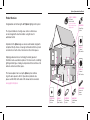
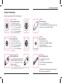
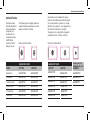
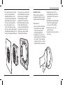
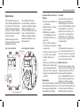
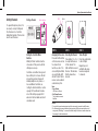
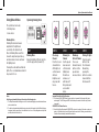
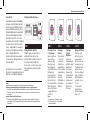
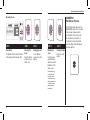
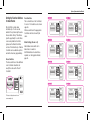
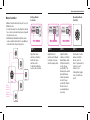
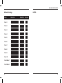
Sphere System
Instruction Manual
Sphere System Instruction Manual
Table of Contents
Product Overview................................................................................................. 4
The Sphere Produt Range.................................................................................... 6
Additional Finishes............................................................................................... 8
Important Information - Read before commencing installation......................... 10
Safety and Installation Warnings........................................................................ 12
Installation Information....................................................................................... 14
Wall and Handheld Controller............................................................................ 16
• Wall Controller.............................................................................................. 16
• Handheld Controller..................................................................................... 19
System Set-up.................................................................................................... 20
Setting Channels................................................................................................ 22
Using Sphere Modes.......................................................................................... 24
• Dimming Mode............................................................................................. 24
• Scene Mode................................................................................................. 26
• Operating Scenes......................................................................................... 28
Setting the Function Switches for more Rooms................................................ 30
Master Controller................................................................................................ 32
• Setting a Master Controller.......................................................................... 32
• Operating a Master Controller...................................................................... 32
Product Specifications and Load Compatibility................................................. 34
Changing Controller Batteries............................................................................ 36
Frequently Asked Questions.............................................................................. 38
3
Sphere System Instruction Manual
Product Overview
GSWHC5 / GSWHC8
5/8 Channel
Hand Controller
Can be set to Master
Mode for whole house
lighting control
Congratulations on Purchasing the GET Sphere lighting control system.
The style and ambience of a single area, room or a whole house
can be changed at the touch of a button, using the latest in
automated control.
All products in the Sphere range are wireless and modular, designed to
compliment lifestyle choices, increasing control and comfort in any room
environment such as the home, hotel rooms or other similar spaces.
GSWCRR5A
Ceiling Relay
Receiver
GSWWC5
5 Channel
Wall controller
Employing advanced wireless technology, the battery operated
Controllers can be used almost anywhere. The Receiver units, controlling
lighting and other types of load, give simple but effective control over the
ambience of rooms and other spaces.
GSWWC8
8 Channel
Wall Controller
This manual explains how to set up the Sphere system and how
to get the best experience from it. If questions or problems arise
please read the FAQ’s at the back of this manual and on our website
www.getplc.com/sphere
GSW10VFLDR
Fluorescent
Dimmer
Receiver
GSWWDR30
Wall Dimmer
Receiver
4
GSWHC5
5/8 Channel
Hand Controller
GSWFDR35
Floor Dimmer
Receiver
GSWCDR35
Ceiling Dimmer
Receiver
5
Sphere System Instruction Manual
The Sphere Product Range
The Sphere range currently offers the following products:
6
GSWHC5 / GSWHC8
Wireless Hand Held Controller
• For use with Sphere Receivers
• Can be used as a Master Controller
• GSWHC5 - For 5 channel dimming /
scene control and other devices
• GSWHC8 - For 8 channel dimming /
scene control and other devices
GSWFDR35
Wireless Floor Receiver
• For use in portable applications
• 1 metre cable from Receiver to BS 1363 plug fused at 5 amp
• Dimming version controls 20W/VA – 350W/VA
GSWWC5 / GSWWC8
Wireless Wall Controller
• For use with Sphere Receivers
• Can be used as a Master Controller
• GSWWC5 - For 5 channel dimming /
scene control and other devices
• GSWWC8 - For 8 channel dimming /
scene control
GSWWDR30
Wireless Wall Receiver
• With integral dimmer control
• Dimming control for 50W/60VA – 300W/VA
• Requires 35mm wall box
• Operates with 5 and 8 channel controllers
GSWCDR35 / GSWCRR5A
Wireless Ceiling Receivers
• For use with Fixed Ceiling and Wall Lights
• Available in Dimmable and Relay versions
• GSWCDR35 - Dimming version controls
20W/VA – 350W/VA
• GSWCRR5A - Relay version for
5 amp on/off switching (2 amp motor load)
GSW10VFLDR
Fluorescent Dimmer Receiver
• For use with Fluorescent Lighting
• 0 – 10V output
• Must be used with dimmable lighting ballast
• Fits into batten fitting
For full details of compliant lamp and other load types for
the above receivers see page 34–35.
7
Sphere System Instruction Manual
Additional Finishes
By using face plates
with alternative finishes,
wall mounted Sphere
components can
be matched to the
comprehensive range
of GET Ultimate
Screwless Flat Plate
wiring accessories.
The following optional 1 gang face plates are
available to purchase separately for use with
Sphere 5 or 8 button controllers:
2 gang plates are also available in the various
finishes for retro-fitting a single Controller module
into a 2 gang wall box, e.g. where a 3 or 4 gang
dimmer is to be replaced. To use 2 gang plates see
the ‘Flush mount’ instructions on page 16.
These plates come complete with a 2 gang grid
mounting frame for 5 or 8 button controllers:
Dimensions: 88mm x 88mm
Dimensions: 148mm x 88mm
FINISH
5 BUTTON
8 BUTTON
5 BUTTON
8 BUTTON
Alternate plates for
Wall Dimmer Receiver
GSWWDR30
Black Nickel
GSW1GFP5BN
GSW1GFP8BN
GSW2GFP5BN
GSW2GFP8BN
GSWWDRFPBN
Pearl Nickel
GSW1GFP5PN
GSW1GFP8PN
GSW2GFP5PN
GSW2GFP8PN
GSWWDRFPPN
Polished Chrome
GSW1GFP5PC
GSW1GFP8PC
GSW2GFP5PC
GSW2GFP8PC
GSWWDRFPPC
Stainless Steel
GSW1GFP5SS
GSW1GFP8SS
GSW2GFP5SS
GSW2GFP8SS
Polished Brass
GSW1GFP5PB
GSW1GFP8PB
GSW2GFP5PB
GSW2GFP8PB
White Metal
GSW1GFP5PW
GSW1GFP8PW
GSW2GFP5PW
GSW2GFP8PW
2 GANG FACE PLATES
1 GANG FACE PLATES
8
9
Sphere System Instruction Manual
Important Information Read before commencing
installation
Maximising Sphere Performance
and Reliability
Sphere is a radio frequency wireless
system, similar to Wi-Fi and Bluetooth
and can similarly be affected by
the surrounding environment. To
ensure maximum performance,
avoid installing Sphere receivers
where the wireless signals between
the controllers and receivers may
be shielded or disrupted by building
materials such as metal foil faced
dry lining or ceiling board, metal foil
faced insulation blocks, metal ceilings,
walls and floors, metal building
frameworks, metal cupboards and
shelving, high efficiency double glazing
and the like. The wireless signal will
travel effectively, without significant
signal loss, through a single ordinary
plasterboard partition, stud wall,
wooden floor etc. However all variants
of hard building materials such as
brick, block, stone and concrete will
reduce the useable range. Range
related issues show as erratic
10
response i.e. loads randomly failing
to change in response to controller
commands. As with other remote
control systems the usual method
of overcoming this is to move closer
to the affected Receivers and/or by
repeating the command.
Typical expected range for 90%
reliability: 30 metres line of sight in
open conditions.
Following the advice below will enable
the best performance to be achieved.
Always:
•Strip the input and output cable
insulation to stated lengths.
•Ensure input and output connections
are tight.
•Use the cable clamp provided.
•Re-fit the Receiver end caps after
wiring.
•Ensure the antenna is kept straight
when placing Receivers in their final
position.
•Try to keep at least 10cm between
Receivers if installing more than one
in an enclosure or distribution board.
•Ensure enclosures for Receivers
have adequate ventilation.
•Try to ensure that the Receivers are
not subjected to strong local radio
frequency fields from equipment
such as CB sets, HAM radio, walkietalkies, emergency services radio
networks etc.
•In ceilings position the Receiver at
least 20cm from recessed luminaires
and lighting transformers.
•Replace the batteries in Controllers
if, in normal use, either or both
Controller LED’s flash when any
button is pushed (see page 36).
Do Not:
•Shorten the Receiver or Controller
antennas or remove the antenna
insulation or make any connection
to the antennas.
•Attempt to operate Receivers from
the output of a preceding Receiver.
•Connect a load type other than that
specified for the particular Receiver*.
•Exceed the maximum rated
connected load of Receivers*.
•Loop in/out on Receiver terminals –
always use a separate junction box.
•Use cable exceeding 1.5mm².
•Place receivers inside metal
enclosures.
•Place Floor Receivers under soft
furnishings, adjacent to sources of
heat or where a trip hazard could
result.
•Locate Receivers adjacent to other
electronic equipment such as
Wireless routers, Modems, Wireless
alarm systems, cordless phones etc.
•Position Receivers where they may
come into contact with water, dust
build up, building debris, paint etc.
•Locate Receivers in conditions
where they could be affected by
condensation or frost.
Avoid:
•Inferior economy or unbranded
mains voltage incandescent or
halogen lamps.
•Low cost dimming electronic
transformers.
* For Receiver loading and load type
compatibility see pages 34–35.
11
Sphere System Instruction Manual
Safety and Installation
Warnings
Read these warnings fully before
starting work and keep them for future
reference.
Note that Sphere is not compatible
and cannot be used with the GET
Smart system.
12
Before commencing installation
please refer to the individual Sphere
Installation and User Guides supplied
with the Receivers for installation
guidance.
These products should be installed
in accordance with the applicable
parts of the Building Regulations, and
the current edition of the IEE Wiring
Regulations (BS 7671: Requirements
for electrical installations) and
appropriate statutory regulations.
In the Republic of Ireland the
installation must be in accordance with
the ETCI National Rules for Electrical
Installations – ET 101.
Before commencing work, switch
OFF the mains supply and remove
appropriate fuse or switch off the
circuit breaker.
When modifying an existing
installation to use the Sphere
system
Check that the existing electrical and
lighting installation is safe and working
correctly before modification.
If there is any doubt how to proceed,
consult a qualified electrician.
When creating a new installation
with Sphere
Sphere can be used to create a
lighting installation without the
necessity of conventional switch
points. However it is recommended
that provision is made available for
the installation of at least one switch
point in each room or space that uses
Ceiling Receivers to aid removal in
case future occupiers want to revert
to a conventional system.
Outdoor Lighting Applications
All outdoor garden installations must
be installed in accordance with IEE
Regulations for Special Installation
Requirements. A 30mA RCD (Residual
Current Device) should always be
placed between indoor and outdoor
electrical circuits, including the initial
connection to an outdoor transformer
used for Low Voltage lighting.
Note that the Floor and Ceiling
Receivers do not have enhanced IP
ratings. They should be either wired
such that they are located indoors
or, if required to be located outside,
housed in a suitable weatherproof
enclosure of at least IP56 rating.
Outdoor enclosures must be
constructed and located such that
the Sphere receivers cannot overheat for example, not in direct sunlight.
13
Sphere System Instruction Manual
Installation Information
Install and set-up (see page 20)
one room at a time. All lighting and
other loads to be controlled must
be connected to a Receiver. The
Controller(s) send signals to the
Receiver(s) and these in turn alter the
state of lighting and other devices
attached to them.
There is no limit to the number of
Receivers on each channel, but each
individual Receiver has a maximum
load that should not be exceeded
(see pages 34-35 and the appropriate
Installation and User guide).
14
Visual Represenation of Channels
The maximum line of sight range is
30 metres. It is always good practice
to mount wall controllers, wherever
possible, such that no Controller is
more than 30 metres from Receivers.
If Sphere is to be installed in more
than one room refer to section ‘Setting
the Function Switches for Different
Rooms’ on pages 30–31 before
starting installation.
15
Sphere System Instruction Manual
Wall and Handheld
Controller Installation
and Set-up
Wall and Handheld Controllers
are programmed and operated in
the same way.
Wall Controller
If positioning in an existing switch
location all cables must be made safe
before proceeding.
The Wall Controllers are supplied
with 2 different fixing options, flush
or surface. Please select the best
method for the situation.
Flush Mount
Flush mounting requires the use
of the Grid frame supplied with the
product to mount the Controller into a
wall box, as used to house standard
light switches. This method is ideal
when an existing light switch is to be
replaced as it will avoid any additional
decorating. The unit will fit into a
16mm deep box when terminated
conductors are not present.
16
Fitting Instructions:
1.Check the wall box and reposition
any terminated conductors and
terminal blocks to ensure that they
do not interfere with the mounting
of the Wall Controller.
2.For installations in metal 1 gang
4 lug boxes the top and bottom
lugs will need to be removed or
bent inwards and out of the way.
3.Remove the face plate prior to
installation by inserting a small flat
blade screwdriver into either of the
two slots on the side of the plastic
frame and gently prising off the
metal plate.
4.Install the grid frame in the wall
box using the screws provided.
The Wall Controller module comes
assembled to the grid frame.
This may be removed to make
installation easier. To remove the
Control module pinch the clips at
the top and bottom of the Control
module and pull it forward. When
the frame is installed the module
can be pressed back into place.
Align the orientation of the module
with the frame (marked TOP).
5.For best performance in both metal
and dry lining boxes, extend the
antenna outside the box through a
knock-out into the wall cavity.
6.Clip the metal front plate onto the
grid frame.
Surface Mount
Surface mounting the Wall Controller
using the pattress supplied avoids
the necessity of cutting a recess in
the wall. This enables location of the
Controller on virtually any surface,
particularly on difficult surfaces such
as glass, tiles, stone walls etc. The
Grid frame is not used.
Fitting instructions:
1.Initially remove the face plate
by inserting a small flat blade
screwdriver into either of the
two slots on the side of the plastic
frame and gently prising off the
metal plate.
2.Remove the Wall Control module
from the grid frame by pinching the
2 clips at the top and bottom of the
unit and pulling the module forward.
3.The Wall Controller pattress can
be fixed in place by two alternate
methods, double sided tape or
screw mounting.
17
Sphere System Instruction Manual
4.For a surface that cannot or should
the circular recesses using a 3.5mm
not be cut or where damage is
drill. Using suitable screws and wall
undesirable the pattress can be
plugs if necessary (not supplied),
secured by using the double sided
mount the pattress in position
tape included. Ensure surfaces are
making sure ‘TOP’ is uppermost.
flat, clean, and dry and dust free.
6.After fixing the pattress in position,
5.For screw mounting, choose a
insert the wall module into the
location for the pattress ensuring
pattress ensuring that the buttons
there are no cables or pipes beneath
are facing the correct way, both
the intended mounting position. From
pattress and module are marked
the inside of the pattress drill through
‘TOP’ and refit the front plate.
18
Handheld Controller
Whilst designed for portable use,
the Handheld Controller can be wall
mounted using the bracket supplied.
Fitting instructions:
1.Choose a location for the bracket.
Ensure that there are no hidden
cables or pipes beneath the
intended mounting position.
2.Pull apart the two sections of the
wall bracket which are held together
by a ‘snap fit’. They are designed
to pull apart. (This acts as a safety
feature when they are on the wall.)
3.Holding the rear section of the
bracket against the wall, mark the
desired position of the screw holes
on the wall.
4.Drill suitable holes and fit wall plugs
(6.5mm for the supplied plugs) as
necessary to suit the wall type.
5.Screw the rear section of the
bracket to the wall.
6.Click the front section back onto the
rear section.
19
Sphere System Instruction Manual
System Set-up
Before starting the set up process
remove the battery shipping tabs from
the Controllers. These are located in
the battery holders (see page 36) of
both types of Controllers. Should the
tabs be missing test the Controller as
described on page 36.
Install the Receivers in line with
the relevant installation instructions
supplied with the Receivers.
Once installed all the Receivers
must be assigned to a channel on a
Controller, by ‘Setting the Channels’,
whether it is intended to use the
Controller in Dimming mode or Scene
mode. A channel functions like a
traditional rotary dimmer, allowing
alteration of the brightness of any
lights attached to it.
BACK OF WALL CONTROLLER :
BACK OF HAND HELD CONTROLLER :
Function Switches
Remove Shipping Tab
20
Controller and Receiver Function
Summary:
•A Receiver can be assigned to any
one of 8 channels.
• All lights assigned to one channel
will operate together.
• Multiple lights can be attached
to each Dimming Receiver, up to
the load limit of the Receiver, see
pages 34–35.
• There is no limit to the number of
Receivers that can be assigned to
a single channel.
• More than one Controller can be used
in each room / area (see page 38).
• Not all the channels have to
be used.
• Relay Receivers and the Fluorescent
Dimmer Receiver switch the load on
at any setting above minimum by
using the ‘up’ button. Pressing and
holding the ‘down’ button will switch
the load off.
Scene Mode
Scene Mode is the preferred way to use
the Sphere system and enables up to
8 different lighting scenes to be created.
A scene is created by adjusting the channels
in a ‘lighting pattern’ or scene and then
setting this scene into the memory of the
receivers. Each scene is assigned to an
individual button on the Controller. Once
set any scene can be recalled at the touch
of its assigned button.
Set Up
The following instructions explain how to
set the channels and then dim them in one
room. Scenes can only be set and operated
once the channels have been set. Dimming
mode can be reverted to at any time.
Multiple Room Set Up
Once the first room is working correctly
read the section of the instructions called
‘Setting Function Switches for Different
Rooms’ (page 30) that explains the
process of setting additional rooms. At
least one Controller is required for each
Dimming Mode
additional room. Setting and using a
Once the channels have been set they Master Controller for use with multiple
can be dimmed up and down in much rooms follows. The function switches can
the same way as a traditional multibe found on the back of the Wall and
way wall dimmer, but wirelessly.
Handheld Controllers (see page 30).
21
Sphere System Instruction Manual
Setting Channels
Setting a Channel
LED
Mode Switches
Button
To operate the Sphere system, it is
necessary to ‘assign’ Ceiling and
Floor Receivers to a Controller,
linking them together. This has to be
done for each Receiver.
22
STEP 1
STEP 2
STEP 3
STEP 4
Setting the Controller Mode
Switches
Initially the ‘Mode’ switches must be
set as above. If they are not, alter the
settings as necessary.
Controllers come with a factory preset
house setting. In most cases this will
not need to be altered. However if
installing multiple room systems, or
to use additional Controllers see
‘Setting the Function Switches’ section
on page 30. You will need to make a
note of this setting on pages 40–41
and also in the User Guide and store it
somewhere safe.
Assigning the Receivers
Press and hold the button
on the Receivers selected
for a channel for at
least five seconds – The
connected lights will flash
once and the Blue LED
will start to flash. Further
receivers can be added to
a channel at any time.
Selecting the Channel
Press button 1– 5 or 1– 8
to assign the Receivers
to that channel. The
lights will flash once and
then rise. This indicates
that the channel has
been set.
Turn off Lights
Press the centre button
to trun off lights.
Repeat steps 2– 4
until all the Receivers
have been assigned
to channels.
Notes:
i. Relay Receiver
LED shows as ‘Orange’
ii. Wall Dimmer Receiver
The front button surrounds
flash Blue.
General:
I. Once set, the channels remain assigned even if the mains supply is removed from the Receivers.
II.If a Receiver button is pressed inadvertently during assigning, the Receiver cannot be taken out of
assign mode (LED flashing). To overcome this situation, assign the Receiver in another channel and
then reassign it to the desired channel.
23
Sphere System Instruction Manual
Using Sphere Modes
Operating Dimming Mode
The system has two modes;
•Dimming mode
•Scene mode
Dimming Mode
Dimming Mode allows manual
adjustment of the light levels
according to the desired mood.
Once in Dimming Mode select the
channel to adjust and press the up
and down arrows to raise and lower
the lighting levels.
STEP 1
STEP 2
STEP 3
STEP 4
STEP 5
Dimming Mode
Ensure the rightmost ‘Mode’ switch is
set to the up position (towards ‘D’).
Pressing the centre button will turn all
lights off or on at maximum and switch
relay loads off or on.
Choosing a
Channel
Press the chosen
channel button.
All the lights set
on that channel
will rise in
brightness and
relay loads will
turn on.
Dimming the
Channel
Use the up and
down arrows to
set the desired
lighting level,
this will now
remain as set
until turned off
Relay loads react
as described
below.
Dimming a
different Channel
Choose an
alternate channel
button. Use the
up and down
arrows as before.
Turning off Lights
Press the centre
button to turn
off all channels.
Alternatively,
pressing the
button of an active
channel will turn
that channel off.
Notes:
Switching non-dimmable lighting and other loads within dimming mode
I. The Relay Receiver allows switching on and off of non-dimmable lighting and small electrical devices
such as extractor fans.
II. To switch non-dimmable loads within dimming mode, select the channel to which the Relay Receiver
is assigned, and then press the up / down buttons to turn it on or off. Any setting above zero (with the
up button) will switch the load to ‘on’.
Important Safety Note for Relay Receivers
III. The Receiver LED is GREEN when the line output is not connected to the line input (the load is
not energised). The LED changes to RED when the output is connected to the line input (the load
is energised).
GSWWDR30 Wall Dimmer Receiver
IV. As with other Sphere Receivers the GSWWDR30 can be set to a channel. It also has up, down and
centre on / off buttons that only control the load directly connected to it. Dimming commands from a
Controller will override settings made with these buttons.
24
25
Sphere System Instruction Manual
Scene Mode
Scene Mode maximises the flexibility
and ease of use that Sphere provides.
‘Scenes’ are preset lighting schemes
and can include the operation of nondimmable lighting and other switched
loads (see Switching below). Scene
Mode allows recall of 5 or 8 scenes,
depending on the Controller. Changing
the whole room to match the activity
is easy - brighter lights for reading or
working, or lower lights for watching
a film or relaxing with friends.
Receivers must have been assigned
to channels (see ‘Setting Channels’) to
use Scene Mode.
For safety reasons we recommend
that Scene 1 is programmed so that all
lights are set to maximum brightness.
Setting and Adjusting Scenes
STEP 1
STEP 2
STEP 3
STEP 4
STEP 5
Setting the Mode Switches
All lights must be turned off before
altering the Mode switches. The
rightmost ‘Mode’ switch must be set to
the down position (towards ‘SC’).
If scene mode is to be the usual mode
this switch will not require any further
operation.
Choosing a Scene
to Programme
Ensure all lights are
turned off. Press
and keep holding
the desired scene
button (lamps will
raise). Whilst keeping
this depressed,
press and hold the
up and down arrow
buttons for at least
five seconds until the
Blue Controller and
Receiver LED’s pulse
– lamps will flash once
and stay on.
Selecting a
Channel
Choose button
1– 5 (or 1– 8)
to select the
channel to be
adjusted (these
are the channels
created during
‘Setting a
Channel’) –
all the lights on
that channel
will flash.
Changing
Channel
Brightness
Use the up
and down arrow
buttons to adjust
brightness of
the channel.
Repeat steps
3 and 4 until all
the channels
have been set
to the desired
light level for
this scene.
Saving and Exiting
Press the centre
button to save the
scene and exit.
The first scene has
now been set. See
‘Operating Scenes’,
page 28, to view
this scene. Repeat
steps 2– 5 until the
desired number of
scenes are set, up
to 5 or 8.
A scene can be
changed at any
time by repeating
steps 2– 5.
Notes:
Saved Scenes are stored even if the mains supply is removed from the Receivers.
Switching non-dimmable lighting and other loads within a scene - using relay receiver
- I.For switched loads, the channel with the Relay Receiver should be included when setting a scene.
II. To switch the load on or off when setting a scene, only use the up / down buttons, do not use the
centre button.
Important Safety Note for Relay Receivers
III. The Receiver LED is GREEN when the line output is not connected to the line input (the load is
not energised). The LED changes to RED when the output is connected to the line input (the load
is energised).
26
Notes:
i. Relay Receiver. LED shows as ‘Orange’.
ii. Wall Dimmer Receiver. The front button
surrounds flash Blue.
27
Sphere System Instruction Manual
GSWWDR30
Wall Dimmer Receiver
Operating Scenes
STEP 1
STEP 2
STEP 3
STEP 4
STEP 5
Scene Mode
The rightmost ‘Mode’ switch must be
in the down position (towards ‘SC’).
Choosing the
Scene
Press the button
of the scene you
wish to use.
Changing Scenes
To use different
scenes press other
buttons.
Dimming the
Scene
Use the up and
down buttons to
adjust the overall
brightness of the
active scene.
Turning off Lights
Press the centre
button.
As with other Sphere Receivers the
GSWWDR30 can be set to a channel.
It also has up, down and centre
on/off buttons. These only control
the load directly connected to it.
Commands from a Controller will
override settings made with the up
and down buttons.
Note: Holding the up
or down button will
eventually raise or
lower all channels to
maximum or minimum.
To restore the scene
press the relevant
scene button.
28
29
Sphere System Instruction Manual
Setting the Function Switches
for more Rooms
Once the first room has been
installed, up to 7 rooms can be
added to the system using the same
House switch setting. This will also
give the opportunity to control these
rooms using a Master Controller
(please see the Master Controller
section of the instructions). A Master
Controller can be added at any time
and will not need any programming.
House Switches
The house switches on the additional
room Controllers should be set
exactly the same as the ‘Room 1
Controller’.
Room Switches
The room switches on the Controller/s
for rooms 1– 8 should be set as shown
opposite.
All House switches in the appropriate
Controllers must be set exactly the
same.
Mode Settings (Rooms 2– 8)
Master/Slave mode switch set to
Slave mode – towards S.
Set Dimmer/Scene mode switch as
required, see ‘Using Sphere Modes’,
page 24.
The house settings above are shown
as an example only.
30
31
Sphere System Instruction Manual
Master Controller
A Master Controller will control Scene 1, in up to
8 different rooms.
•In order to be able to use the Master Controller
two or more rooms must have been set up with
the same house code.
•Both Wall and Handheld Controllers can be
used as a Master Controller. It is an additional
Controller to the others in the system.
Master
Controller
can be 5 or
8 channel
wall/remote
controller
32
Setting a Master
Controller
Operating a Master
Controller
STEP 1
STEP 2Adjust the
STEP 3
STEP 4
Adjust the House
switches so that they
match the House
switches on the
Controller/s within the
rooms to be controlled.
Adjust the Room
switches on the Master
Controller so they are
all in the down position.
Adjust the Mode
switches so that the
Master/Slave switch
(left function switch)
is set to the up
position (M). The
dimmer/scene switch
(the right function
switch) should also
be set to the up
position (D). Master
Mode is now set,
no programming is
necessary.
Press button 1 on the
master controller to
turn on scene 1 in
Room 1, press button 2
to turn on scene 1
in Room 2, etc.
Centre button toggles
scene 1 in all Rooms
on/off.
33
Sphere System Instruction Manual
Product Specifications and Load Compatibility
SPHERE COMPONENT
Ceiling/Floor
Dimmer Receiver
GSWCDR35
GSWFDR35
Lamp / Load Type
Low Voltage (12V) Halogen Lamps
Dimming electronic or Magnetic transformer (4)
Min 20W/VA
Max 350W/VA
Y
DIMMING
Wall Dimmer
Receiver
GSWWDR30
Fluorescent
Dimmer Receiver
GSW10VFLDR
Max 800W / 4 ballasts
Min 50VA/60W
Max 300W/VA
Y - (trailing edge
electronic transformers only)
N
SWITCHING
Ceiling Relay
Receiver
GSWCRR5A
Max 5A
(2A motor load) (1)
Y - on/off only
Y
N
Y - on/off only
Linear Fluorescent Lamps
T8 and High Output T5 lamps
N
N
Y - on/off only
Linear Fluorescent Lamps
T4 lamps and T5 4 – 13W lamps
N
N
Y (only with 1–10V control
electronic ballast)
Y - on/off only
N
N
Y (only with 1–10V control
electronic ballast)
Mains GLS / Reflector etc, Mains (230 / 240V)
Halogen Lamps (3)
Compact Fluorescent Lamps with separate
ballasts
CFLi lamps (including those marked ‘dimmable’)
Light-Emitting Diode (LED) (Solid State Lighting)
Light-Emitting Diode (LED) (Solid State Lighting)
High Intensity Discharge Lamps
Other Loads: Relay, contactor, ceiling fan,
wall fan, extractor fan etc
Luminaires that already incorporate a dimmer
Notes :
34
Y
4 pin lamps
‘Plug-in’ Compact Fluorescent Lamps
Mains voltage lamps
When used with separate driver
Motor Load
Father / child up lighter etc
1 For higher loads use a suitable contactor
2. Dimmable LED lamps may be suitable for use with Ceiling / Floor Dimmer Receivers, if
designed for use with triac (leading edge) type dimmers. Dimmable LED lamps may be
compatible with the Wall Dimmer Receiver if designed for use with trailing edge type dimmers.
3 Avoid using inferior economy or unbranded mains voltage incandescent or halogen lamps.
N
N
N (2)
N (2)
N
N
N
N
N
N
Y - on/off only
N
Y - on/off only
N
N
Y (with 1–10V control driver)
N
N
N
Y - on/off only
Y - on/off only
N
Y-on/off only Max 400W(1)
N
N
Y - on/off only
Notes : 4 Using dimming electronic transformers and low voltage halogen lamps eliminates potential
end of life issues with mains halogen and incandescent lamps. When dimming with electronic
transformers check minimum loading with manufacturer. Do not use toroidal (round shape)
magnetic transformers unless specifically stated by the manufacturer to be dimmable. Do not
mix electronic and magnetic transformers on the same Receiver.
35
Sphere System Instruction Manual
Changing Controller
Batteries
Wall Controller
To access the battery holder remove
the control module from either the
The expected life of the Controller
surface mounting pattress box or the
batteries is approximately 2 years
flush mounted grid plate.
with typical usage. Batteries require
First, unclip the face plate from the
replacement when one or both of
back box or grid frame.
the Blue LED’s on the front of the
Remove the control module by
controller flash when any Controller
pressing the top two clips inwards
button is held down. Sphere
and ease out the module.
Controllers require 2 x CR2032 type
The battery compartment is on the
batteries. Always replace batteries in
pairs and from the same manufacturer. side of the module. Slide out the
battery holder from the module casing
Since scene information is held in
and invert to release the discharged
the receivers, scenes will not be lost
batteries.
during battery changing.
Wall Controller
Control Module
Replace the 2 x CR2032 button cell
batteries fitting them both with the
positive (+) symbol facing up. Do
not use pliers or tweezers to hold
the batteries as this could cause a
malfunction. Slide the battery holder
back into the module casing. Ensuring
the control module has the ‘TOP’
mark uppermost, reassemble the
Wall Controller.
Pattress Box
Handheld Controller
To change the batteries in the
Handheld Controller press in the
button located at the base of the back
cover and remove it, exposing the
battery holder.
Slide out the holder and remove the
discharged batteries by inverting
the holder. Replace the 2 x CR2032
button cell batteries fitting them both
with the positive (+) symbol facing
up. Do not use pliers or tweezers
to hold the batteries as this could
cause a malfunction. Slide the
battery holder into the Controller
casing. Reassemble the Handheld
Controller.
Handheld Controller
Face Plate
Slide out battery holder
2 x CR2032 batteries
36
Wireless Remote Controller
Release button
Slide out battery holder
37
Sphere System Instruction Manual
Frequently Asked Questions
Can I have more than one Controller in a
room?
Multiple Controllers can be used to control
the same lights in a room (e.g. 1 Wall
Controller and 1 Handheld Controller).
Controllers are added by simply duplicating
the Haze, Room and Mode switch settings
on each of the additonal Controllers. Note
if a Controller sends the same command as
the previous command sent from another
Controller, there will be no response. A
second button push will be required. (This
is a result of the last Controller command
information being held only in the Receivers).
One Controller can dim the channels and an
alternate Controller can operate scenes. To
do this set the dimming/scene switch to ‘D’
or ‘SC’ as required.
How do I replace a lost or damaged
Controller?
If a Controller is damaged or lost, obtain a
replacement and find the record made of the
switch settings on the old Controller then
duplicate these exactly on the new Controller.
Since all the channel and scene settings are
stored in the Receivers, no reprogramming
is necessary.
38
Where should I install the Controllers?
Once programming the Receivers has
finished, position the Controller(s). As the
system is wireless these can be positioned
anywhere in the home, taking into account
range limitations (page10). A fixed Controller
by the door of every room equipped with
Sphere will be easy to find when entering
or exiting.
What is happening if the lighting seems to
change by itself?
Sphere control commands are heavily
encrypted. As such unexpected changes to
the lighting in one or more rooms can only
be caused by Sphere Controllers that have
the same switch settings being operated
nearby, for instance in adjacent rooms or
neighbouring apartments that have the
Sphere system. The best way to avoid
conflicting operation is to plan the switch
settings in advance for all adjacent and
nearby systems. However it is still possible
that interference could occur if a new Sphere
system is installed locally. In this case, the
House switch settings on the Controller of the
affected room(s) will need altering as follows.
(Note that access to the Receivers will be
required to press the Receiver buttons during
this process).
1. Change the coding of the House switches
on the Controller of an affected room by
moving one (or more) switch to its alternate
position. The associated Receivers will
no longer respond. Note that at least one
switch needs to be in the up position.
2. Check that the new switch setting does not
interfere with other rooms or neighbouring
systems.
3. Once a House switch setting has been
found that does not interfere with other
Sphere systems the channels of the
associated Receivers will need to be
reassigned as described in the ‘System set
up’ section, page 20, in effect starting a new
installation. As long as the Receivers are
assigned to the same channels as before,
stored scenes will be not be affected.
4. If there are more Controllers for the same
room, their switch settings should also be
updated. Ensure a note is made of the new
switch settings.
Following a period of successful installation
and use:
1. If there is no response to Controller
commands.
a) Check that the mains supply to the
installation is still in place, i.e. no MCB’s
have tripped.
b) Check that the controller LED’s light when
a button is pushed and that the batteries
are OK as described on page 36.
c) Ensure no room or house switch has been
changed inadvertently.
d) Ensure there are working lamps running
from affected Receivers / in affected
channel(s).
e) Check the points above, and then gain
access to and observe at least one of the
Receivers (if installed a Floor Receiver is
most convenient) to see if the Receiver
LED flashes when the centre button of a
Controller is pushed.
f) If all checks are OK and the fault still
occurs, contact the Helpline, page 43.
2. If any of the lighting loads develop
unusual behaviour e.g. flicker or cannot
be turned off.
a) Check that the relevant connected load
is the correct type (pages 34–35).
b) Disconnect the supply to the system by
tripping the appropriate circuit breaker /
removing the circuit fuse, then reconnect
the supply by resetting the circuit breaker
/ replacing the fuse (if in doubt contact
a qualified electrician) then operate the
system.
c) If after carrying out the above the behaviour
continues to occur, contact the Helpline,
page 41.
If there are any more questions about the
Sphere system or how to use it and to find out
about updates and more FAQ’s, please visit
the website www.getplc.com/sphere
39
Sphere System Instruction Manual
NOTES :
Dill Switch Settings
Room
House Code
Room Code
Function
Room 1
Room 2
Room 3
Room 4
Room 5
Room 6
Room 7
Room 8
Room 9
Room 10
Room Master 1
Room Master 2
40
41
Sphere System Instruction Manual
NOTES :
Important Information
The Sphere Wall and Handheld
Controllers, GSW35FDR Floor Dimmer
Receiver and the batteries in the
Controllers fall within the scope of
the Waste Electrical & Electronic
Equipment Directive 2002/96 EC.
(WEEE)
They should not be disposed of with
household waste.
Please recycle where facilities exist.
Check with your local authority for
recycling advice.
Should any difficulty be experienced
with installation or operation of the
Sphere system please telephone our
Customer Helpline on 0121 565 7770
Helpline Hours:
Monday – Thursday 8.30am – 5.30pm
Friday 8.30am – 4.15pm
Or visit for advice:
www.getplc.com/sphere
GET reserves the right to make
changes to the appearance,
specification of any product without
prior notice to customers.
All intellectual property rights in this
product are proprietary and may
not be used without consent. Any
enquires should be made to GET.
42
43
AR1596 Ed A
GET Key Point 3-17 High Street Potters Bar EN6 5AJ England
[email protected]
www.getplc.com/sphere