1
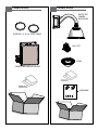
© 2009-2010, Moog Videolarm, Inc. All Rights Reserved PDW7CS-9 Explosion-Proof: Purge/Pressurization Unit www.videolarm.com Installation and Operation Instructions for the following models: PDW7CN-9 PDW7CS-9 IP Network Ready 7” Explosion-Proof PurgeDome™ Outdoor PTZ Camera Systems for Hazardous environments UL approved for Class 1, Division II applications. Includes Purging System and Lines. With 23x zoom Day/Night camera, MPEG-4 & MJPEG video compression, Full D1. Clear dome, with 24VAC input, heater/ blower Analog 7” Explosion Proof PurgeDome™ Outdoor PTZ Camera Systems for Hazardous environments UL approved for Class 1, Division II applications. Includes Purging System and Lines. With 23x zoom Day/Night camera, MPEG-4 & MJPEG video compression, Full D1. Clear dome, with 24VAC input, heater/ blower Before attempting to connect or operate this product, please read these instructions completely. To be used with the 81-IN5409 Instruction Manual. CERTIFIED 81-IN5410 10-19-2010 IMPORTANT SAFEGUARDS 1 Read these instructions. 2 Keep these instructions. 3 Heed all warnings 4 Follow all instructions. 5 Do not use this apparatus near water. 6 Clean only with damp cloth. 7 Do not block any of the ventilation openings. Install in accordance with the SAFETY PRECAUTIONS CAUTION RISK OF ELECTRIC SHOCK DO NOT OPEN manufacturers instructions. 8 Cable Runs- All cable runs must be within permissible distance. 9 Mounting - This unit must be properly and securely mounted to a supporting structure capable of sustaining the weight of the unit. Accordingly: a. The installation should be made by a qualified installer. b. The installation should be in compliance with local codes. c. Care should be exercised to select suitable hardware to install the unit, taking into account both the composition of the mounting surface and the weight of the unit. 10 Do not install near any heat sources such as radiators, heat registers, stoves, or other apparatus ( including amplifiers) that produce heat. 11 Do not defeat the safety purpose of the polarized or grounding-type plug. A polarized plug has two blades with one wider than the other. A grounding type plug has two blades and a third grounding prong. The wide blade or the third prong are provided for your safety. When the provided plug does not fit into your outlet, consult an electrician for replacement of the obsolete outlet. 12 Protect the power cord from being walked on or pinched particularly at plugs, convenience receptacles, and the point where they exit from the apparatus. 13 Only use attachment/ accessories specified by the manufacturer. 14 Use only with a cart, stand, tripod, bracket, or table specified by the manufacturer, or sold with the apparatus. When a cart is used, use caution when moving the cart/ apparatus combination to avoid injury from tip-over. 15 Unplug this apparatus during lighting storms or when unused for long periods of time. 16 Refer all servicing to qualified service personnel. Servicing is required when the apparatus has been damaged in any way, such as power-supply cord or plug is damaged, liquid has been spilled of objects have fallen into the apparatus, the apparatus has been exposed to rain or moisture, does not operate normally, or has been dropped. Be sure to periodically examine the unit and the supporting structure to make sure that the integrity of the installation is intact. Failure to comply with the foregoing could result in the unit separating from the support structure and falling, with resultant damages or injury to anyone or anything struck by the falling unit. UNPACKING Unpack carefully. Electronic components can be damaged if improperly handled or dropped. If an item appears to have been damaged in shipment, replace it properly in its carton and notify the shipper. Be sure to save: 1 The shipping carton and packaging material. They are the safest material in which to make future shipments of the equipment. 2 These Installation and Operating Instructions. SERVICE If technical support or service is needed, contact us at the following number: TECHNICAL SUPPORT AVAILABLE 24 HOURS 1 - 800 - 554 -1124 CAUTION: TO REDUCE THE RISK OF ELECTRIC SHOCK, DO NOT REMOVE COVER ( OR BACK). NO USER- SERVICEABLE PARTS INSIDE. REFER SEVICING TO QUALIFIED SERVICE PERSONNEL. The lightning flash with an arrowhead symbol, within an equilateral triangle, is intended to alert the user to the presence of non-insulated “dangerous voltage” within the product’s enclosure that may be of sufficient magnitude to constitute a risk to persons. Este símbolo se piensa para alertar al usuario a la presencia del “voltaje peligroso no-aisIado” dentro del recinto de los productos que puede ser un riesgo de choque eléctrico. Ce symbole est prévu pour alerter I’utilisateur à la presence “de la tension dangereuse” non-isolée dans la clôture de produits qui peut être un risque de choc électrique. Dieses Symbol soll den Benutzer zum Vorhandensein der nicht-lsolier “Gefährdungsspannung” innerhalb der Produkteinschließung alarmieren die eine Gefahr des elektrischen Schlages sein kann. Este símbolo é pretendido alertar o usuário à presença “di tensão perigosa non-isolada” dentro do cerco dos produtos que pode ser um risco de choque elétrico. Questo simbolo è inteso per avvertire I’utente alla presenza “di tensione pericolosa” non-isolata all’interno della recinzione dei prodotti che può essere un rischio di scossa elettrica. The exclamation point within an equilateral triangle is intended to alert the user to presence of important operating and maintenance (servicing) instructions in the literature accompanying the appliance. Este símbolo del punto del exclamation se piensa para alertar al usuario a la presencia de instrucciones importantes en la literatura que acompaña la aplicación. Ce symbole de point d’exclamation est prévu pour alerter l’utilisateur à la presence des instructions importantes dans la littérature accompagnant l’appareil. Dieses Ausruf Punktsymbol soll den Benutzer zum Vorhandensein de wichtigen Anweisungen in der Literatur alarmieren, die das Gerät begleitet. Este símbolo do ponto do exclamation é pretendido alertar o usuário à presença de instruções importantes na literatura que acompanha o dispositivo. Questo simbolo del punto del exclamaton è inteso per avvertire l’utente alla presenza delle istruzioni importanti nella letteratura che accompagna l'apparecchio. LIMITED WARRANTY FOR VIDEOLARM INC. PRODUCTS VIDEOLARM INC. warrants this Product to be free from defects in material or workmanship,as follows: PRODUCTCATEGORY PARTS LABOR All Enclosuresand Electronics Five (5) Years Five (5) Years Pan/Tilts Three (3) Years **6 months if used in autoscan Three (3) Years **6 months if used in autoscan /tour operation Poles/PoleEvators Three (3) Years /tour operation Three (3) Years Warrior/Q-View/I.R.Illuminators Five (5) Years Five (5) Years Five (5) Years **6 months if used in autoscan SView Series Five (5) Years **6 months if used in autoscan /tour operation Controllers Five (5) Years /tour operation Five (5) Years PowerSupplies Five (5) Years Five (5) Years AccessoryBrackets Five (5) Years Five (5) Years During the labor warranty period, to repair the Product,Purchaserwill either return the defective product, freight prepaid, or deliver it to Videolarm Inc. an equal degree of protection with a Decatur GA.The Productto be repaired is to be returned in either its original carton or a similar package RMA# (Return Materials Authorization number) displayed on the outer box or packing slip. To obtain a RMA#you must contact our TechnicalSupport Team at 800.554.1124,extension 101.Videolarm will return the repaired Productfreight prepaid to Purchaser.Videolarm is not obligated to provide Purchaserwith a substitute unit during the warranty period or at any time. After the applicable warranty period, Purchasermust pay all labor and/or parts charges. The limited warranty stated in these product instructions is subject to all of the following terms and conditions: TERMS AND CONDITIONS 1. NOTIFICATIONOF CLAIMS: WARRANTYSERVICE: If Purchaser believes that the Product is defective in material or workmanship, then written notice with an explanation of the claim shall be given promptly by Purchaser to Videolarm but all claims for warranty service must be made within the warranty period. If after investigation Videolarm determines that the reported problem was not covered by the warranty, Purchaser shall pay Videolarm for the cost of investigating the problem at its then prevailing per incident billable rate. No repair or replacement of any Product or part thereof shall extend the warranty period as to the entire Product. The warranty on the repaired part only shall be in for a period of ninety (90) days following the repair or replacement of that part or the remaining period of the Product parts warranty, whichever is greater. 2. EXCLUSIVE REMEDY: ACCEPTANCE:Purchaser’s exclusive remedy and Videolarm’s sole obligation is to supply (or pay for) all labor necessary to repair any Product found to be defective within the warranty period and to supply, at no extra charge, new or rebuilt replacements for defective parts. 3. EXCEPTIONS TO LIMITED WARRANTY: Videolarm shall have no liability or obligation to Purchaser with respect to any Product requiring service during the warranty period which is subjected to any of the following: abuse, improper use: negligence, accident, lightning damage or other acts of God (i.e., hurricanes, earthquakes), failure of the end-user to follow the directions outlined in the product instructions, failure of the end-user to follow the maintenance procedures recommended by the International Security Industry Organization, written in product instructions, for regular or recommended in the service manual for the Product. Furthermore, Videolarm shall have no liability where a schedule is replacement or maintenance or cleaning of certain parts (based on usage) and the end-user has failed to follow such schedule; attempted repair by personnel; operation of the Product outside of the published environmental and electrical parameters, or if such Product’s original (trademark, serial number) markings have been defaced, altered, or removed. Videolarm excludes from warranty coverage Products sold AS IS and/or WITH ALL FAULTS and excludes used Products which have not been sold by Videolarm to the Purchaser. All software and accompanying documentation furnished with, or as part of the Product is furnished “AS IS” (i.e., without any warranty of any kind), except where expressly provided otherwise in any documentation or license agreement furnished with the Product. 4. PROOF OF PURCHASE: The Purchaser’s dated bill of sale must be retained as evidence of the date of purchase and to establish warranty eligibility. DISCLAIMEROF WARRANTY EXCEPT FOR THE FOREGOING WARRANTIES, VIDEOLARM HEREBY DISCLAIMS AND EXCLUDES ALL OTHER WARRANTIES, EXPRESS OR IMPLIED, INCLUDING, BUT NOT LIMITED TO ANY AND/OR ALL IMPLIED WARRANTIES OF MERCHANTABILITY, FITNESS FOR A PARTICULAR PURPOSE AND/OR ANY WARRANTY WITH REGARD TO ANY CLAIM OF INFRINGEMENT THAT MAY BE PROVIDED IN SECTION 2-312(3) OF THE UNIFORM COMMERCIAL CODE AND/OR IN ANY OTHER COMPARABLE STATE STATUTE. VIDEOLARM HEREBY DISCLAIMS ANY REPRESENTATIONS OR WARRANTY THAT THE PRODUCT IS COMPATIBLE WITH ANY COMBINATION OF NON-VIDEOLARM PRODUCTS OR NON-VIDEOLARM RECOMMENDED PRODUCTS PURCHASER CHOOSES TO CONNECT TO PRODUCT. LIMITATION OF LIABILITY THE LIABILITY OF VIDEOLARM, IF ANY, AND PURCHASER’S SOLE AND EXCLUSIVE REMEDY FOR DAMAGES FOR ANY CLAIM OF ANY KIND WHATSOEVER, REGARDLESS OF THE LEGAL THEORY AND WHETHER ARISING IN TORT OR CONTRACT, SHALL NOT BE GREATER THAN THE ACTUAL PURCHASE PRICE OF THE PRODUCT WITH RESPECT TO WHICH SUCH CLAIM IS MADE. IN NO EVENT SHALL VIDEOLARM BE LIABLE TO PURCHASER FOR ANY SPECIAL, INDIRECT, INCIDENTAL, OR CONSEQUENTIAL DAMAGES OF ANY KIND INCLUDING, BUT NOT LIMITED TO, COMPENSATION, REIMBURSEMENT OR DAMAGES ON ACCOUNT OF THE LOSS OF PRESENT OR PROSPECTIVE PROFITS OR FOR ANY OTHER REASON WHATSOEVER. Content of Box Content of Box PROTECTED CAMERA ENCLOSURE SUPPLIED 1/4 “ & 3/8 ” POLY TUBING PAN / TILT DOME PURGE / PRESSURIZATION UNIT HARDWARE 1 Unit is shipped with 100’ (max) flex tubing (3/8” & 1/4”) to connect enclosure to purge pressurized unit. 2 fitting are provided as shown in the diagrams. 2 ENCLOSURE SUPPLY OUTLET (3/8 “ Push-in Fitting) ENCLOSURE REFERENCE INLET (1/4 “ Push-in Fitting) PURGED / PRESSURIZATION UNIT ELECTRICAL ALARM WIRING CONDUIT AND SEAL (Customer Supplied) SYSTEM SUPPLY INLET (3/8 “ SS Compression Fitting) 3 English NOTES • To ensure adequate protective gas flow to the protected enclosure, all piping and tubing must be fully reamed. • Precaution must be taken to prevent crimping and other damage to protective gas piping and tubing. Caution must be used when opening/closing swing panel to prevent tubing kinks. • Supplied 1/4” & 3/8” Poly Tubing have ferrule, nut & insert preset. Use that end for connecting to power box. Cut other end to attain desired length and connect to push-in fittings on Purge/Pressurization Unit. • The Tamper-Proof (Primary) Regulator is intended to prevent tampering, while allowing a more stable setpoint to be achieved in the small, tightly sealed enclosure where the protective gas flow is critically low and difficult to stabilize. A 5/64” Hex Key or Allen Wrench is required to operate. • When performing Initial Purge/Pressurization, adjust Primary Regulator to 5 psi. Normal operating pressure is 2.5 inches of water at Dome Pressure Gauge. Balance Primary and Secondary Regulators for continuous purge by alternately adjusting Primary (5 psi) and Secondary (2.5 inches of water). 4 SYSTEM MOUNTING O 0.32 4 places 10.0 PEPPERL+ FUCHS 14.7 5 TUBING CONNECTION DIAGRAMS ENCLOSURE SUPPLY OUTLET ENCLOSURE REFERENCE INLET PEPPERL+ FUCHS PURGE/PRESSURIZATION UNIT SYSTEM SUPPLY INLET 6 TUBING CONNECTION DIAGRAMS DOME PRESURE GAUGE [ENCLOSURE] EXP PRESURE SWITCH ATMOSPHERIC REFERENCE SDOEN OF WOSTOE .3 .2 .1 .4 SAFE 0 HIGH LOW .5 ENCLOSURE PRESSURE REFERENCE OFF PRIMARY REGULATOR SYSTEM SUPPLY INLET SECONDARY REGULATOR ON 5 500 4 400 3 300 2 20 1 10 SUPPLY METER FLOWMETER PROTECTED CAMERA ENCLOSURE 7 CONNECTION SIZES, LENGTHS & BENDS CAMERA PEPPERL+ FUCHS REFERENCE GAS SUPPLY (System Supply) PROTECTED CAMERA ENCLOSURE CAMERA PURGE/PRESSURIZATION UNIT SUPPLY System Supply 3/8” OD SS Tubing Fully Reamed MAXIMUM: 20 ft / 10 bends Camera Supply Camera Reference SUPPLIED 3/8” Poly Tubing SUPPLIED 1/4” Poly Tubing 100 ft MAX 100 ft MAX SET-UP PROCEDURE • See supplied Model 1001A Installation and Operation Manual for Class I Purging Set-up. The use of a temporary SCFH flowmeter is unnecessary. Use the permanently installed flowmeter on the swing panel in the Purge/Pressurization Unit. • See supplied Model 1001A Installation and Operation Manual for additional installation and operation information. 8 POLE MOUNT CLIPS 9 REMOVE INSERT CAMERA ENCLOSURE POWER SUPPLY BOX DOME TRIM RING PAN TILT UNIT Carefully unpack both boxes and compare with parts list. Open the metal power supply box on the camera enclosure and remove cardboard packing materials. 10 11 WALL MOUNT: Attach unit securely to the wall mount using (4) 3/8” or 8mm hardware (not supplied). 12 INPUT: (120VAC 1A 240VAC .5A) 220-240VAC INPUT The power box may be pole mounted with the pole support clips. (Stainless steel straps not provided). 13 110-120VAC INPUT 240Vac 120Vac Input Input The box is designed for either 120 or 240 VAC input single phase. Line (L) and Neutral (N) wires should be connected as marked on the board and plugged into the corresponding voltage for the input single phase. Main Switch Connect incoming ground to ground post as shown. OUTPUT: (24VAC 84VA) 14 HEATERS CAMERA 52 WATTS MAX 32 WATTS MAX Connect Housing Power 24Vac Power To Housing Optional 24Vac Output Main Switch Internal resettable fuses are supplied for the main 24VAC output lines. Do not connect heaters to camera output. The PB24 is not designed for 3 phase or 208V systems. 15 16 CAPTIVE SCREW Remove Pan/ Tilt from shipping carton. Install in base bracket in housing. To secure in place, tighten captive screw. See S-View Pan/Tilt instructions for additional details. • If required the Pan/ Tilt and dome may be installed before mounting the entire assembly. 17 18 To install the dome align the tabs and twist counter clockwise to secure. Hand tighten the screws on the dome. Recommended torque 12 inches/lb (1.35Nm). Part Number Replacement Parts List 1 2 Description 1 RP65PT851200 PAN TILT 2 PR25DCP71000 TRIM RING ASSEMBLY WITH CLEAR DOME Product Registration/Warranty Thank you for choosing Videolarm. We value your patronage and are solely committed to providing you with only the highest quality products available with unmatched customer service levels that are secondto-none in the security industry. Should a problem arise, rest assure that Videolarm stands behind its products by offering some of the most impressive warranty plans available: 3 Years on all Housings, Poles, Power Supplies, and Accessories and 5 Years on all camera systems (SView, QView, Warriors), and InfraRed Illuminators. Register Your Products Option 1: Online Option 2: Mail-In Take a few moments and validate your purchase with our Online Product Registration Form www.videolarm.com/productregistration.jsp at or complete and mail-in the bottom portion of this flyer. Register your recent Videolarm purchases and benefit from the following: • Simple and Trouble-Free RMA process • Added into customer database to receive product updates / news • Eliminate the need to archive original purchase documents: Receipts, Purchase Orders, etc… Cut at the dotted Line Place in envelope, affix stamp and mail to: Main Contact Info First Name: Professional Title: Company: Address 1: Address 2: City: State / Province/Country: Zip / Postal Code: Phone Number: Product Information Last Name: Please Circle One: Product Description Serial # (Available only for Camera Systems, IR Illuminators, Wireless Devices) PO# E-mail Address: Name & Location of Company / Store where Purchased: (City, State, Country) Videolarm Product ID Videolarm ATTN: Warranty 2525 Park Central Ave. Decatur, GA 30035 Business Personal