1
ALESIS
QS7.1 and QS8.1
Reference Manual
INTRODUCTION
Thank you for purchasing an Alesis QS7.1/QS8.1 64-Voice Expandable Synthesizer.
It’s a powerful instrument and we’re sure you will find it exciting to use. The more
you know about it the more you’ll be able to do, so we recommend that you make
good use of this manual.
But most importantly, don’t forget to have fun! (There’s a good reason they call
what musicians do playing.)
HOW T O U SE T HIS MANUAL
No manual can cover the needs of all musicians. There are simply too many of you,
and your needs are too different. But we’ve tried to make this a document that will
teach you what you need to know while encouraging you to explore new and
interesting territory.
It is divided into eleven parts. How many of these sections you need to read will
depend on what you want to do with your QS.
Part 1: SETUP & CONNECTIONS covers how to hook up your QS so it can be turned
on and played. This section also contains useful audio basics, some tips on wiring
and power, and directions for connecting your QS to other MIDI gear.
Part 2: OVERVIEW introduces the front panel controls and LCD, along with the
terms and internal structures that every QS owner ought to know. Here is where
you’ll learn what all the buttons do, and how the sounds are organized. This
chapter also covers the Card expansion options you have available.
Part 3: FIRST SESSION starts you playing.
Part 4: BASIC OPERATION takes everything in the First Session one step further.
After covering this material you’ll be a QS performance wizard, fully versed in
how to use the instrument’s Programs and Mixes and how to change Global settings.
It’ll also take you through the basics of using the [STORE] button to save your
edits, how to go about naming them, and the procedures for playing back sequences
from a card.
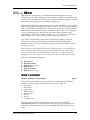
Part 5: MIDI is for players who want to use their QS for MIDI performance and
sequencing. Because it’s relevant, you’ll also find a little here about the very top
level of Mix editing. Sys-ex transfer operations are also covered in this section.
Part 6: EDITING EFFECTS will show you how to modify the the matrix of effects
processors that are built into your QS. This is useful to know even if all you want to
do is “play the presets,” because even if you love a particular sound you might find
that its current processing doesn’t quite fit in with your music. Need to lengthen or
shorten a Program’s reverb time? Extend a delay? Make an echo louder? Or maybe
even shut the effects completely off, so you can run a raw signal into your mixing
deck or external effects processor? This is where you’ll find the answers.
QS7.1/QS8.1 Reference Manual
1
Contents
Part 7: EDITING MIXES takes you to the next level of editing power, showing you
how to change the preset Mixes and put together new ones of your own. It also
explains the parameters which give the QS its strength as a master MIDI
keyboard.
Part 8: EDITING PROGRAMS gets deep into the instrument. If you are interested in
pushing the QS synthesis engine to the max — and it’s a powerful engine, it really
is — then you’ll want to study this section very closely.
Part 9: EXTRAS includes all sorts of fun and useful information that doesn’t fit
neatly into the other sections. This is where to look for discussion of RAMcards,
Sound Bridge, the QS CD-ROM, and other things of general interest.
Part 10: APPENDICES contains reference material on service and maintenance,
troubleshooting, and the QS’s MIDI Implementation.
Part 11: Index lists some key parameters and concepts alphabetically, along with
the page numbers on which you will find the most information about the item you
are researching.
MANUAL CONVENTIONS
All buttons, knobs, and switches on the QS are referred to in bracketed capital
letters that match the instrument’s actual markings. Here are some examples:
[PROGRAM] means the button to the right of the LCD that says “PROGRAM” on it.
[ PAGE] and [PAGE ] refer to the two buttons on the left of the LCD that have
left-and-right cursors on them.
[CONTROLLER D] is the slider on the right side of the slider grouping, with “D”
printed underneath.
[00 PIANO] refers to the leftmost button in the top row of numbered buttons.
Sometimes this will be shorthanded as [00], depending on what’s being discussed.
[PITCH] is the control wheel at the left side of the instrument.
And [SUS PEDAL] is the rear panel jack you’d plug your sustain pedal into.
2
QS7.1/QS8.1 Reference Manual
Unpacking and Inspection
The shipping carton for your QS should contain the following items:
•
•
•
•
•
•
✪
QS (with the same serial number as shown on the shipping carton)
Sustain pedal
AC Power Cable
Computer CD-ROM containing software
This instruction manual, plus Mix and Program lists and a Quick Start guide
Alesis warranty card
If you haven’t filled out your warranty card and mailed it back to us, please take
the time to do so. This will help us give you the best support we possibly can.
QS7.1/QS8.1 Reference Manual
3
Table of Contents
CONTENTS
Part 1: SETUP & CONNECTIONS .........................................................9
AC Power...............................................................................................................9
Audio....................................................................................................................10
MIDI.....................................................................................................................12
Direct Computer Link.............................................................................................14
Pedal and Footswitch Hookup................................................................................16
Digital Audio/Optical Hookup..............................................................................16
48 kHz Input..........................................................................................................17
Part 2: OVERVIEW ............................................................................19
A Quick Tour Of The Front Panel.............................................................................19
Programs, Mixes, And Banks...................................................................................24
The Performance Controls.......................................................................................26
PCMCIA Expansion Cards......................................................................................28
Part 3: FIRST SESSION ......................................................................29
Powering Up..........................................................................................................29
Playing the Demo Sequences...................................................................................29
Playing Programs...................................................................................................30
Playing Mixes........................................................................................................31
The Performance Controls, Pt. II..............................................................................33
Transposing The Keyboard.........................................................................33
Performance Transposition Chart................................................................34
Part 4: BASIC OPERATION.................................................................35
Recap....................................................................................................................35
The Double-Button Press Trick................................................................................35
Copying Existing Programs And Mixes To A New Location In The User Bank.............36
…Or To A New Location On A Card Bank................................................................36
Changing The Programs In A Mix............................................................................37
Storing Altered Mixes To The User Bank (Or To A Card)..........................................37
Storing Altered Programs To The User Bank (Or To A Card).....................................37
Changing The Name Of A Program Or Mix..............................................................38
Compare Mode.......................................................................................................38
Playing Sequences From A Card..............................................................................39
The Global Settings (And How To Change Them)....................................................40
Part 5: MIDI .....................................................................................49
The Power of Mix Mode..........................................................................................49
Using an External Sequencer....................................................................................50
Program Assign for each MIDI Channel...................................................................52
Sending and Receiving Bank Select Messages..........................................................52
Using the QS6.1 as a Master Keyboard....................................................................54
Saving Programs via MIDI Sys Ex...........................................................................58
Editing Programs via MIDI Sys Ex..........................................................................59
Part 6: EDITING EFFECTS ..................................................................61
Basic Info...............................................................................................................61
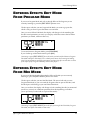
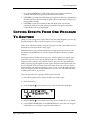
Entering Effects Edit Mode From Program Mode.......................................................62
Entering Effects Edit Mode From Mix Mode..............................................................62
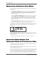
Navigating In Effects Edit Mode.............................................................................63
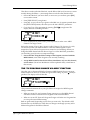
Selecting From Among The Available Effects Patches In A Mix....................63
The “FX Program Change via MIDI” function..............................................64
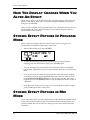
How The Display Changes When You Alter An Effect.............................................65
QS7.1/QS8.1 Reference Manual
5
Table of Contents
Storing Effect Patches In Program Mode..................................................................65
Storing Effect Patches in Mix Mode.........................................................................65
Copying Effects From One Program To Another........................................................66
Keeping Track: The Interaction Of Effects, Programs, And Mixes..............................67
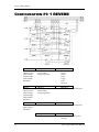
Picking An Effect Configuration..............................................................................67
Configuration #1: 1 REVERB...................................................................................68
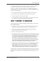
Configuration #2: 2 REVERBS.................................................................................70
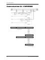
Configuration #3: LEZLIE+REVERB.......................................................................72
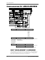
Configuration #4: 1 REVERB+EQ............................................................................73
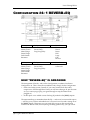
Configuration #5: OVERDRIVE+LEZLIE................................................................74
Routing Sounds or Programs Through The Effects Only.............................................75
Setting Effect Send Levels......................................................................................76
If The Send Inputs Clip...........................................................................................76
[00] to [30] —Effect Sends 1 - 4................................................................................76
EQ.........................................................................................................................77
Mod.......................................................................................................................78
Lezlie....................................................................................................................81
Pitch.....................................................................................................................83
Delay....................................................................................................................89
Reverb ..................................................................................................................90
Overdrive..............................................................................................................96
Effect Mix..............................................................................................................97
Part 7: Editing Mixes........................................................................99
What is a Mix?......................................................................................................99
Polyphony in Mix Play Mode..................................................................................99
Program Assign for each MIDI Channel...................................................................99
Mix Edit Mode.......................................................................................................100
Understanding the Edit Buffers..............................................................................101
Level Setting for Each Program...............................................................................102
Pitch.....................................................................................................................103
Effect.....................................................................................................................103
Keyboard/MIDI.....................................................................................................104
Controllers.............................................................................................................105
Setting the Range...................................................................................................106
Naming a Mix........................................................................................................106
Part 8: Editing Programs……………………………………………………………………………..107
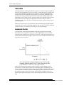
Overview..............................................................................................................107
The “Normalized” Synth Voice..............................................................................107
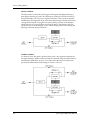
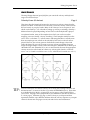
How the QS6.1 Generates Sound.............................................................................108
Program Sound Layers............................................................................................108
QS6.1 Signal Flow..................................................................................................109
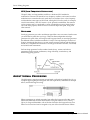
About Modulation..................................................................................................111
About Signal Processing..........................................................................................112
Drum Mode............................................................................................................113
Storing Your Edited Programs.................................................................................114
Program Edit Functions...........................................................................................115
Voice.........................................................................................................116
Muting and Unmuting Sounds..........................................................116
Level.........................................................................................................119
Pitch.........................................................................................................120
Filter.........................................................................................................123
Amp/Range...............................................................................................126
Pitch Envelope...........................................................................................130
Filter Envelope..........................................................................................133
Amp Envelope............................................................................................136
6
QS7.1/QS8.1 Reference Manual
Table of Contents
Name........................................................................................................138
Mod 1 – Mod 6.............................................................................................139
Pitch LFO..................................................................................................144
Filter LFO.................................................................................................146
Amp LFO...................................................................................................147
Tracking Generator.....................................................................................149
Programming Drum Sounds in Drum Mode................................................................151
Voice.........................................................................................................151
Level.........................................................................................................153
Pitch.........................................................................................................153
Filter.........................................................................................................154
Amp/Range...............................................................................................154
Amp Envelope............................................................................................155
Mute Group....................................................................................155
Special Programming Functions...............................................................................156
Copying Sounds..........................................................................................156
To Audition Programs Before Storing...........................................................157
Part 9: Extras…………………………………………………………………………………………………159
A Word About the QS CD-ROM..............................................................................159
Sound Bridge™..........................................................................................159
Using PCMCIA Expansion Cards.............................................................................160
Saving the User Bank to a PCMCIA Card....................................................160
Loading a Bank from an External Card........................................................161
Storing an Individual Program or Mix .........................................................162
Loading an Individual Program or Mix........................................................162
Card Storage Ramifications...................................................................................163
More about SRAM Cards.............................................................................164
SRAM Cards and Mix Mode........................................................................164
Part 10: Appendices…………………………………………………………………………………….165
Appendix A...........................................................................................................165
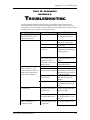
Troubleshooting.........................................................................................165
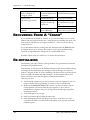
Recovering From A “Crash”............................................................166
Re-initializing..............................................................................166
Checking The Software Version......................................................167
Maintenance/Service.................................................................................167
Cleaning your QS6.1.......................................................................167
Preventative Maintenance..............................................................167
Refer All Servicing to Alesis..........................................................167
Obtaining Repair Service...............................................................168
Appendix B: MIDI Supplement...............................................................................169
MIDI Basics...............................................................................................169
MIDI Hardware.........................................................................................169
MIDI Message Basics..................................................................................170
Channel Messages: Mode Messages.................................................170
Channel Messages: Voice Messages.................................................170
Continuous Controllers List.............................................................171
System Common Messages...............................................................172
General MIDI.............................................................................................172
MIDI Implementation Chart......................................................................174
Appendix C: Parameters Index................................................................................175
Program Edit Parameters............................................................................175
Mix Edit Parameters..................................................................................177
Part 11: Index………………………………………………………………………………………………179
QS7.1/QS8.1 Reference Manual
7
Table of Contents
8
QS7.1/QS8.1 Reference Manual
Setup & Connections: Part 1
PART 1
SETUP & CONNECTIONS
AC POWER
HOOKUP
Your QS7.1/QS8.1 is set to work with the voltage of the country to which it was
shipped (either 110 or 220V, 50 or 60 Hz) and comes equipped with the appropriate
power cable.
Hooking that cable up is simple.
•
Make sure your QS is turned off.
•
Plug the female (jack) end of the power cable into the QS’s power socket.
•
Plug the male (plug) end into a source of AC power. It’s good practice not to turn
the QS on until all other cables are hooked up.
The IEC-spec power cable included with your QS is designed to connect to an outlet with
three holes, the third of which — the round one — is the ground connection. This
connection is an important safety feature: it keeps the QS’s chassis at ground potential,
preventing accidental shocks.
Unfortunately, not all three-hole sockets are properly grounded. We recommend that
you use an AC line tester to check the ground connection on any socket you may use, just to
be on the safe side. If you find an ungrounded outlet, consult with a licensed electrician
about getting the problem fixed.
✪
Avoid using ungrounded outlets. Plugging the QS into an ungrounded outlet can be
hazardous. The same goes for “lifting” the unit off ground by using a three-to-two
plug adapter. Don’t do it!
✪
Alesis cannot be responsible for any problems that might be caused by using the
QS with improper AC wiring.
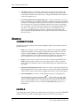
LINE CONDITIONERS AND PROTECTORS
The power coming through some AC lines contains voltage surges, spikes, or transients
that can stress your gear, causing failure or malfunctions. Although the QS is designed
to tolerate typical voltage variations, it isn’t invulnerable. So if the power in your area
is particularly bad (or if you are out playing live gigs) you will probably want to take
precautions. You have three basic options:
•
Line spike/surge protectors. These relatively inexpensive devices are designed
to protect against strong surges and spikes. They act somewhat like fuses and
will have to be either replaced or reset (depending on the unit) if they’ve been
hit by an extremely strong spike.
QS7.1/QS8.1 Reference Manual
9
Part 1: Setup & Connections
•
Line filters. These cost more than simple spike/surge protectors, but may be
worth it depending on your situation. Along with surge protection they offer
circuits that can remove some line noise — things like dimmer hash, transients
from other appliances, etc.
•
An Uninterruptible Power Supply (UPS). This is the most expensive way to go,
but it is also the best. Your typical UPS offers complete line protection/filtering
and throws in emergency battery power that will come on instantly if there is a
power outage. This will prevent anything in RAM-only memory from getting
lost, and enable you to take the time to shut down everything properly. That
last step is very important. You should always turn everything in your rig
p h y s i c a l l y off when the power goes out — otherwise you risk serious gear
and/or speaker damage from the current surge that takes place when power is
finally restored.
A UDIO
CONNECTIONS
The QS has two Main outputs and a stereo headphone output. These make for several
possible hookups:
•
Mono. To run in mono, connect a single mono cable from one of the QS’s [MAIN]
output jacks to either a mono amp or an individual mixer input. (You can use
either the [LEFT MAIN] or the [RIGHT MAIN] output jack.) Please note that
with this connection you will only be hearing one channel, so any Programs or
Mixes designed for stereo output will sound incomplete or diminished.
•
Stereo. To run in stereo, connect two mono cords (one each from the [LEFT] and
[RIGHT] output jacks) to either (A) a stereo amp system or (B) two separate
mixer inputs. For full effect, make sure that these inputs are panned hard left
and right.
•
Dual Stereo/Four Individual Outs. Connect two mono cords from the [LEFT] and
[RIGHT] MAIN OUTPUT jacks and two mono cords from the [LEFT] and [RIGHT]
AUX OUTPUT jacks to a dual stereo amplification system, or four mixer inputs.
•
Stereo Headphones. To listen over headphones, plug a set of high-quality
stereo headphones into the headphones [
] jack on the rear panel. The
volume for the headphone output is controlled by the front panel [VOLUME]
slider. Some headphones have a higher electrical resistance than others; if
the sound level seems too low even with the [VOLUME] slide up full, try a
different set.
LEVELS
To get the highest audio quality when performing or recording, set your QS’s [VOLUME]
slider all the way up. If the resulting signal is too loud (“hot”) for your mixer or
10
QS7.1/QS8.1 Reference Manual
Setup & Connections: Part 1
recording deck, lower the input level controls on those units until they are no longer
clipping.
AUDIO CABLES — SELECTION, ROUTING,
AND CARE
The audio connections between your QS and the rest of your studio are your music’s
lifeline, so make sure you use high-quality cables. These should be low-capacitance
shielded cables, with a stranded internal conductor and a low-resistance shield. Avoid
cables with solid internal conductors.
Quality cables cost more, but they are worth it. If you want to the lowest possible noise
and the best possible sound, there is no other way to go. As for what to do with them
when setting up, here are some basic mistakes to avoid:
•
Do not bundle audio cables with AC power cords. If you do, the audio cables
will pick up hum from the AC line.
QS7.1/QS8.1 Reference Manual
11
Part 1: Setup & Connections
•
Avoid running audio cables near such sources of electromagnetic interference as
transformers, monitors, computers, etc.
•
Don’t run cables where they can be stepped on. Stepping on a cable will
compress the insulation between the center conductor and shield, and over time
this will degrade performance and reliability.
•
Avoid twisting the cable or laying it out with sharp, right-angle turns.
•
Never unplug a cable by tugging on the cable itself. Even if it has a “strainrelief” plug, you are likely to damage the inside wiring and connections. The
best way to unplug a cable is to firmly grasp the body of the plug and then pull
it straight outward.
When connecting audio cables, or turning power on and off, make sure that ALL
devices in your system are turned off and ALL volume controls are turned down.
This is important. If you don’t do this, you can create loud bursts of sound that
might damage your speakers (or worse, your ears).
✪
MIDI
BASIC MIDI HOOKUP
MIDI is the standard data communication protocol for electronic musical instruments. If
you aren’t familiar with MIDI, see Part 5: MIDI and Part 10: Appendices to learn more
about how it works. Meanwhile, here’s all you need to know to get wired up.
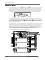
The QS has three MIDI connectors:
•
MIDI IN. This port is for receiving MIDI information (notes, program changes,
etc.) from another source, such as another MIDI keyboard, an alternate
controller, or a computer.
•
MIDI OUT. This port is for sending MIDI information to another MIDI
keyboard, sound module, or computer.
•
MIDI THRU. This port is for passing on MIDI information received by the MIDI
IN port. In simple MIDI setups, the THRU port is used to connect additional
devices that will all be “listening” to the same source.
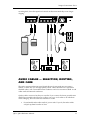
Here are four typical MIDI setups for your QS, and the appropriate cable connections
for each of them:
•
12
As Slave. To play your QS from any other MIDI device (keyboard, drum pad,
guitar or bass controller, sequencer, etc.), just run a standard 5-pin MIDI cable
from the control device’s MIDI OUT to the QS’s [MIDI IN] jack.
QS7.1/QS8.1 Reference Manual
Setup & Connections: Part 1
QS7.1/QS8.1 Reference Manual
13
Part 1: Setup & Connections
14
•
As Controller. To play other MIDI devices from your QS, run a MIDI cable from
the QS’s [MIDI OUT] jack to the MIDI IN of the device you want to control.
•
As a Link in a “daisy chain.” If you are using the QS in the middle of the MIDI
chain (example: as the second unit of a three device chain), you’ll need two
MIDI cables. Attach one from the MIDI OUT of the chain’s first device to the
[MIDI IN] jack of the QS; and then attach the other from the QS’s [MIDI THRU]
jack to the MIDI IN of the chain’s third device.
•
As part of a computer-based MIDI Network. If you are using a computer for
sequencing and/or programming, you’ll want to be able to play data into your
computer from your QS, and receive data back as well. This will take two MIDI
cables. Attach one from the MIDI OUT of the computer’s MIDI interface to the
[MIDI IN] jack of the QS; and then attach the other from the QS’s [MIDI OUT]
jack to the interface’s MIDI IN.
QS7.1/QS8.1 Reference Manual
Setup & Connections: Part 1
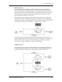
DIRECT C OMPUTER L INK
The QS can communicate directly with Mac or PC computers via its [SERIAL PORT]
connector. Using this connection eliminates the need for a MIDI cables and a separate
MIDI interface.
Here’s how it works:
1) Run a single serial cable from your computer’s serial port to the [SERIAL PORT]
connector on your QS.
2) Set the rear panel [ PC / MAC ] switch to either PC or MAC, depending on
what kind of computer you are using.
3) Set your QS to listen to data over this direct serial connection, instead of MIDI.
To do this, press [EDIT SELECT] to begin editing; then press [BANK ] to access
Global Edit Mode; then press [ PAGE] until the lower line of the LCD reads
I/O. (If you overshoot, just press the [PAGE ] button to get back.) Once there,
use the [VALUE] buttons to change the setting from MIDI to whatever best
matches your computer. There are three options:
•
PC 38.4Kbd. Use this setting if your computer is a PC and its serial port runs
at 38.4 kilobaud.
•
PC 31.25Kbd. Use this setting if your computer is a PC and its serial port
runs at 31.25 kilobaud.
•
MAC 1MHz. Use this setting if your computer is a Macintosh.
Please note that if the rear-panel selection switch is set to [MAC], your QS will not
show you the two PC choices. Likewise, if the switch is set to [PC], then the Mac setting
will not show up in the display.
QS7.1/QS8.1 Reference Manual
15
Part 1: Setup & Connections
IBM® PCS AND COMPATIBLES RUNNING
WINDOWS ®
If you want to link your QS directly with a PC or PC-Compatible, you’ll need special
serial driver software and cabling.
You’ve already got the driver software — it’s in the \ALESIS\ASDWIN directory on
the CD-ROM that came with your QS. (If you don’t have a CD-ROM drive in your
computer, call Alesis Product Support and ask them to send you the software on a 3-1/2
inch floppy disk. ) Complete installation instructions come with the driver software.
The procedure will vary depending on your version of Windows.
The special cable can be purchased through Alesis Product Support. It has a DIN8
connector on one end and either a DB9 or DB25 connector on the other end (depending on
the type of connector that is on your PC.) The DIN8-to-DB9 cable is part # 9-96-1290.
The DIN8-to-DB25 cable is part # 9-96-1291.
Be aware that many PCs have more than one serial port, and some have both types of
connector. Before you order a cable from us you will need to (A) identify the port you
wish to hook up to, and (B) make certain it is not already in use by the computer.
MACINTOSH™
You don’t need a special cable to make a direct connection between your QS and a Mac.
Any standard Mac DIN-8 cable will do.
You will, however, have to choose between using the MODEM or PRINTER serial port
on the Mac. Plug into whichever one you aren’t already using, and then make sure your
MIDI software’s port selection is set to match.
If both ports are already in use, you can either (A) temporarily disconnect your modem
or printer, or (B) buy a multiple serial port box that will let you hook everything up to
your Mac and switch among these serial devices as needed.
NOTE: If you want to use the printer port for your direct serial link, first make certain
that AppleTalk is disabled.
16
QS7.1/QS8.1 Reference Manual
Setup & Connections: Part 1
PEDAL AND FOOTSWITCH HOOKUP
The QS keyboard has three back-panel pedal jacks, marked [SUS PEDAL], [PEDAL 1]
and [PEDAL 2].
[SUS PEDAL] is designed to work with any standard momentary footswitch. It doesn’t
matter whether the footswitch is normally open or closed, so long as you plug it into the
jack before powering up your QS; the instrument will automatically sense the
footswitch’s polarity and calibrate itself accordingly.
[PEDAL 1] and [PEDAL 2]. are designed to work with a Roland EV-5 volume pedal (or
its equivalent).
The QS’s factory defaults assign sustain to the [SUS PEDAL] jack and overall
instrument volume to the [PEDAL 1] jack, but you can change these settings at any time
if you want to. There are lots of interesting possibilities to explore. A starter example:
using a footswitch to turn vibrato on in a program, and using a volume-type pedal to
control vibrato speed.
If your sustain footswitch responds backwards (i.e., notes sustain unless the footswitch
is pressed), then turn off your QS and make sure the footswitch plug is fully inserted
into the [SUS PEDAL] jack. When it is, turn the instrument’s power back on while
keeping your foot off the footswitch.
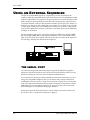
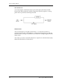
DIGITAL A UDIO /O PTICAL HOOKUP
The QS can output digital audio directly into an Alesis ADAT, ADAT-XT, or
ADAT-compatible multitrack digital recorder via fiber optic cable.
The QS’s [DIGITAL OUT] carries all four audio outputs of the QS (Main and Aux,
Left and Right) on a single fiber optic cable. Fiber optic cables of various lengths
are available from your Alesis dealer. The model OC cable is 5 meters long and is
the maximum length recommended.
Note: This will not plug directly into a tape deck which uses S/PDIF or AES/EBU
for its digital input! A digital audio format converter of some sort must be used.
To hook up the optical cable between the QS and an ADAT-XT:
❿ Remove the two pieces of clear plastic, tubular sleeving (if present) that
protect the tips of the optical cable plug.
❡ Insert one cable end into the QS [DIGITAL OUT] and the other end into the
ADAT-XT’s DIGITAL IN.
To test the cable and QS digital output, plug one cable end into the QS. The other
end should emit a soft red light (it is not dangerous to look directly at this light).
R ECORDING D IGITAL A UDIO
Once the fiber optic connection is made between the QS and ADAT-XT, the QS will
output audio on the first four channels of the digital bus (the bus is capable of
handling eight channels of digital audio). The MAIN [LEFT] and [RIGHT] outputs
QS7.1/QS8.1 Reference Manual
17
Part 1: Setup & Connections
are routed to channels 1 and 2, while the AUX [LEFT] and [RIGHT] outputs are routed
to channels 3 and 4. Note that the [VOLUME] slider does not control the level going
to the ADAT-XT. Volume control must happen via MIDI or a Pedal plugged into the
Pedal 1 jack.
When recording to ADAT-XT (or some other digital audio recorder), it must be set to
“slave” to the 48kHz clock embedded in the digital audio which the QS is sending.
This clock can be set to either 48kHz or 44.1kHz, as determined by the Clock
function (found in Global Edit Mode, Page 19). The Clock function has four settings:
Int 48kHz, Int 44.1k, Ext 48kHz and Ext 44.1k. The default setting
is Int 48kHz, which is suitable when the digital recorder is using the 48kHz
sample rate. However, if the recorder is using the 44.1kHz sample rate, the Clock
function should be set to Int 44.1k. This ensures that the QS will be in tune
with previously recorded material. See page 47 in Chapter 4: Basic Operations for
more information on the Clock parameter.
48 KHZ IN
If your ADAT system has an Alesis BRC Remote Controller, the QS’s digital clock
must be synchronized to the clock coming from the BRC. This requires that a
connection be made providing the clock signal to the QS and that the QS’s Clock
function be set to either one of its two external settings (Ext 48kHz or Ext
44.1k).
Connect a BNC-to-BNC cable (such as the Alesis BN cable) between the BRC’s 48
kHz CLOCK OUT and the QS’s [48 KHZ IN]. Set the Clock function to either Ext
48kHz if the BRC is set to 48kHz, or Ext 44.1k if the BRC is set to 44.1kHz
(“Pitched Down” to -147).
Tip: With this type of connection, the ADAT-XT tracks will remain in tune with
the QS even when the BRC’s pitch value is adjusted.
18
QS7.1/QS8.1 Reference Manual
Setup & Connections: Part 1
Note: When using ADAT-XTs without the BRC, it is not necessary to connect the 48
kHz Clock. If set up properly, the XTs will “slave” to the QS’s Digital Output.
QS7.1/QS8.1 Reference Manual
19
Overview: Part 2
PART 2
OVERVIEW
A Q UICK T OUR OF T HE FRONT PANEL
THE WHEELS
At the far left of the front panel you will find two powerful controllers:
•
The [PITCH] wheel. Move this control up or down to expressively bend the pitch
of the synth.
•
The [MODULATION] wheel. Move this control to cause interesting sonic changes
in the current Program or Mix.
Sometimes you won’t hear anything happen when you use the [MODULATION]
wheel. In these cases, either (A) the current Program or Mix isn’t programmed
to respond to modulation, or (B) modulation is tied to a function that is currently
off. Here’s an example of the latter: if the [MODULATION] wheel is
programmed to control chorus speed, but chorus d e p t h is currently set at zero,
then moving the [MODULATION] wheel won’t do anything audible.
THE SLIDERS
Moving to the right, you will see 5 different sliders:
•
The [VOLUME] slider. This fader raises and lowers the QS7.1/QS8.1’s audio
output level.
•
[CONTROLLERS A, B, C, and D]. These faders are programmable and can be
used to give you hands-on control of many different parameters. What they do
will vary depending on how the Program or Mix has been designed. As you move
them, the LCD gives you visual feedback in the form of small vertical bargraphs. Please note: this only happens if a control function is assigned to the
slider being moved. That means the quickest way to find out which sliders are
working in a given Program is to push all four sliders up while watching the
display.
During editing, the [CONTROLLER D] slider serves as a data entry control.
QS7.1/QS8.1 Reference Manual
19
Part 2: Overview
THE EDIT MODE BUTTONS
There are 6 buttons grouped together at the immediate left of the display:
20
•
[▲ VALUE]. When you are editing, this button increments the selected value. At
all other times it steps you forward through the available Programs or Mixes,
depending on which mode you’ve selected.
•
[VALUE ▼]. Same as [▲ VALUE], except that it decrements values and steps
backward through Programs and Mixes.
•
[EDIT SELECT]. This button takes you into Edit Mode. To get back out, press
either [MIX] or [PROGRAM].
•
[STORE]. A true multi-purpose control. It is involved in making MIDI sys-ex
transfers, in saving and loading both User and Card Banks, in copying Effects
patches, and when initializing individual Sounds within a Program. When
editing, this is the button you’d press to store an altered Program or Mix to a
selected location in the QS’s memory. In normal performance it gives you a quick
way to copy the current Program or Mix to a new location.
•
[ PAGE]. When editing, this button cycles you backward through the
available “pages” for the current parameter (there’s an indicator in the upper
right of the LCD that tells you what page you are on). In Program Mode, this
button changes your QS’s basic MIDI channel. In Mix Mode, it is used to display
the Programs assigned to different MIDI channels, so that you can change these
assignments on the fly.
•
[PAGE ]. Same as just above, except that it cycles you forward instead of
backward.
QS7.1/QS8.1 Reference Manual
Overview: Part 2
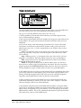
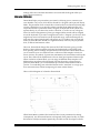
THE DISPLAY
The large backlit LCD in the center of the front panel gives you visual feedback as
you work. What it shows will vary depending on the mode you are in.
Let’s go over what the different areas of the LCD “tell” you.
1) The big numbers on the left side of the LCD show you which Program or Mix
you’re currently editing or playing.
2) The top line of the display shows the NAME of the Program or Mix while you’re
in Play Mode. It also gives you the name of the selected Function when you’re in
Edit Mode.
3) If you look closely at the silkscreening around the LCD's "bezel" (the raised,
clear plastic cover between it and the dusty outside world), you'll notice some
abbreviations like "CLP" or "TRN" alongside the word "NAME". Here is what
they stand for:
CLP: An exclamation point (!) will appear in this area of the LCD if the QS's
signal clips internally. You'll only see this in Program or Mix Modes (not while
you're editing).
SEQ: A blinking arrow (->) will appear in this area of the LCD if you have
triggered a card sequence. When the sequence stops, the arrow will disappear.
TRN: An up or down arrow will appear in this area of the LCD if you have
transposed the keyboard up or down.
ABCD: If a Program or Mix has any of the four faders active, you can move
them and see a reaction in the LCD under these four letters. The four vertical bar
graphs represent the [CONTROLLER A-D] slider positions. This area of the LCD
will also display the “page” numbers when you are in any of the Edit Modes.
4) The middle line does triple duty. In Play Mode it tells you which Bank the sound
you’re using came from. In Edit Mode it gives you the name of the parameter you’re
editing. And in Mix Program Select mode, it lets you know which QS Program is
assigned to which MIDI channel. More on that later in the manual.
5) These words let you know which Mode you are in. You’ll see them alone or in
combination depending on where you are. The word “EDIT” changes to “EDITED”
when you change a value in one of the Edit Modes.
6) The numbers along the bottom are the MIDI channel numbers. In Program Mode
you’ll only see one channel number lit at a time. In Mix Mode you’ll see two or more.
When activity is happening on a given channel, a circle will light up around that
MIDI channel's number. This is true whether the information is generated from the
QS's keyboard or comes in via the MIDI In jack.
QS7.1/QS8.1 Reference Manual
21
Part 2: Overview
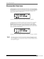
THE PLAY MODE BUTTONS
There are 4 buttons grouped together at the immediate right of the display:
•
[MIX]. This button takes you to Mix Mode.
•
[PROGRAM]. This button takes you to Program Mode.
•
[ BANK]. In Program and Mix Modes, this button cycles you backward through
all available Banks. In Edit Mode this becomes the [COMPARE] button, which
shifts between the original and edited versions of a Program or Mix, so you can
hear both while you make your changes.
•
[BANK ]. In Program and Mix Modes, this button cycles you forward through
all available Banks. In Edit Mode it becomes the [GLOBAL] button, taking you
to 18 pages of controls that affect the overall operation of your QS (including
Master Tune, Controller Assignments, Keyboard Response Curves, and more).
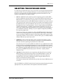
THE SELECTION BUTTONS
There are 23 buttons grouped together at the right side of the front panel, arranged
in two rows (an upper row of 13, and a lower row of 10). These [SELECTION] buttons
are used to quickly choose among Programs, Mixes, Sound parameters, MIDI channel
assignments, etc. — whatever is available in the QS’s current mode.
•
[00] through [120]. When you are playing Programs or Mixes, these buttons jump
your selection by tens — for example, if Program 79 is selected and you press [20],
your QS will shift to Program 29. When you are editing, they select one of the
three parameters printed just above them, depending on which Edit Mode you
are in.
•
[0] through [9]. When you are playing Programs or Mixes, these buttons jump
your selection within the currently selected Sound Group — for example, if
Program 24 is selected and you press [7], your QS will shift to Program 27. When
you are editing, they select one of the three parameters printed just below
them, depending on what Edit Mode you are in.
Most of these buttons are also used in Sequence selection and playback, as discussed
on the next page.
22
QS7.1/QS8.1 Reference Manual
Overview: Part 2
A WORD ABOUT THE SILKSCREENING
As we mentioned in the last section, if you look above and below the 23
[SELECTION] buttons you’ll see a lot of words silkscreened on the front panel. We’ll
get into what they mean later. All you need to know now is:
• When you’re in Mix Edit mode, find the word “MIX” at the outer edge of the
buttons, and then follow along that level to find the various Mix functions.
• Do the same for Program and Effects Edit modes. The exception here is that
there’s no bottom row of functions for Effects Edit mode. In its place you have “Drum
Sound” , which means you use these buttons to select Drums in Drum Mode. The
“Keyboard Sound” row calls up more Program Edit mode functions.
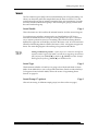
THE SEQUENCE & TRANSPOSE BUTTONS
At the far right on the front panel are two buttons:
[SEQUENCE]. Pressing this button once puts your QS in Sequence Playback Mode. In
this mode the [00] through [90] buttons select possible PCMCIA card Sequence
Banks, and the [0] through [9] buttons trigger specific Sequences for playback. To
exit without making a selection, just press [SEQUENCE] again.
[TRANSPOSE]. You can transpose the output of your QS by holding this button
down and then pressing any key on the keyboard. The transposition limit is one
octave in either direction. To return to normal operation, just stop pressing on the
[TRANSPOSE] button. Please note that any changes you make here will stay in
place until you deliberately reset them to normal. This is done by holding the
[TRANSPOSE] button and pressing the third C key from the left (also known as
C3). To make it easy to locate, we’ve silkscreened that on the front panel just above
the key.
QS7.1/QS8.1 Reference Manual
23
Part 2: Overview
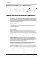
PROGRAMS, MIXES, AND B ANKS
Your QS comes with 1,140 built-in Programs and Mixes. At any time you can also
add hundreds more just by putting QCards or RAMcards into the [PCMCIA
EXPANSION CARD] slots.
That’s a lot of different sounds!
In order to easily find the ones you need, you will need to know how they are
arranged. Starting with…
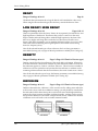
WHAT’S A PROGRAM?
A QS Program is a set of parameters which (A) create a specific sound and (B) can
be recalled instantly at the touch of a button. There are lots of parameters, which is
why many thousands of cool Programs are currently available from Alesis and
third-party sources. And, of course, you can always edit these parameters yourself
to create Programs that are uniquely your own.
There are 640 internal Programs, divided into 5 Banks of 128 Programs each (more
about Banks in a moment). To get instant access to more Banks, simply insert an
Alesis QCard into one or both of the [PCMCIA EXPANSION CARD] slots. You can
also add Banks using RAMcards, assuming Program data is stored on them.
Each Program consists of from 1 to 4 different Sounds which can be combined and
processed in many different ways: layered on top of one another, for example, or
split up to cover different sections of the keyboard, or set to play (or not play)
depending on how hard you strike a key.
The number of Sounds being used by a Program has a direct effect on your QS’s
polyphony, because each Sound takes one Voice to play. If your current Program uses
only one Sound, you’ll be able to play 64 simultaneous notes. By contrast, a Program
using two Sounds will run out of Voices twice as fast, limiting you to 32 simultaneous
notes. And a Program that uses four Sounds will limit you to 16 notes of polyphony.
WHAT’S A MIX?
A Mix is a combination of Programs selected from the available Banks. Most Mixes
have only two or three Programs in them, but you can put together as many as 16 if
you want. You can also arrange them in a number of useful ways, creating layered
combinations, split combinations, and more.
There are 500 internal Mixes, arranged 100 per Bank. More can be accessed at any
time using expansion cards, as mentioned above for Programs.
For those of you who do MIDI sequencing, one of the most useful Mixes will be #00 in
the User Bank. This is the multi-timbral Mix. It lets you assign different Programs
24
QS7.1/QS8.1 Reference Manual
Overview: Part 2
to each of 16 different MIDI channels, making it easy to build anything from a
small pop/rock ensemble to a complete orchestra.
QS7.1/QS8.1 Reference Manual
25
Part 2: Overview
WHAT'S A BANK?
A Bank is a collection of 128 Programs and 100 Mixes. There are five internal Banks
available in the QS, and even more can be accessed if you have put QCards or
RAMcards into one or both of the [PCMCIA EXPANSION CARD] slots.
The different banks are:
USER
PRESET1
PRESET2
PRESET3
GenMIDI
Card A [if in use; invisible if not]
Card B [if in use; invisible if not]
If a card has more than one Bank, the numbers will go up like so: CardA-1, CardA2, CardA-3, etc.
While playing Programs or Mixes, the current Bank is named in the second line of
the LCD display. To cycle through all the Banks that are available, press the
[BANK] buttons on the front panel. You can also change Banks by using standard
MIDI Bank Select commands (various values of Controller 0).
Two things to remember about Banks:
1) Each Bank contains its own unique collection of Programs and Mixes. This means
that Program 10 in PRESET1 is different from Program 10 in PRESET3…
although they may be similar if they belong to related Sound Groups (see the
next page for a quick explanation of Sound Groups).
2) A Mix can contain Programs from any Bank. This includes Banks which might
be on a QCard or an SRAM card. (If the Mix you’ve called up uses a card-based
Program, make sure the Program’s card is in the right expansion slot. If you
have the wrong card in the slot, the Mix will call up the wrong Program. And if
you have no card in the slot at all, that part of the Mix won’t sound.)
26
QS7.1/QS8.1 Reference Manual
Overview: Part 2
ABOUT SOUND GROUPS
To make things easier for you, we’ve broken down three of the five Banks into Sound
Groups . There are 12 different Sound Groups with 10 Programs each, plus a 13th
Sound Group with only 8 Programs. (This gives each Bank 128 Programs, as
specified by the MIDI standard.) Each of these Groups is clearly marked on the
[SELECTION] button that calls it up.
Why do we call them Sound Groups? Because they bring together Programs which
are musically or sonically related, such as pianos [00], guitars [30], bass [40] and
drums [120].
There are two Banks which differ from this default scheme:
•
The User Bank. Straight from the factory, your QS’s User Bank is organized in
the same Sound Groups as the Preset Banks. But it needn’t stay that way. Any
User Bank you create for yourself (or collect from non-Alesis sources) might be
organized very differently.
•
The General MIDI Bank. This is organized to match the General MIDI
standard, which puts Programs in a totally different order than that of our
Sound Groups.
T HE PERFORMANCE C ONTROLS
There are a number of expressive ways to control the sound of your QS while you are
playing. They are:
•
Velocity. This refers to how slow or fast you strike the keys. In most Programs,
faster means louder. Velocity can also cause tonal changes in the sound, trigger
new Sound layers in a Program, or do other things entirely. It all depends on
what parameters are set to respond to it, and how.
•
Aftertouch. Strike a key, hold it down…and then push it down a little harder.
That’s “aftertouch.” (You’ll also see it referred to as “Pressure” in some
instruments and software.) Common uses include triggering changes in the pitch,
tone, or volume of notes.
•
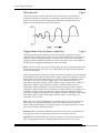
Pitch Bend Wheel. Push the [PITCH BEND] wheel up and the pitch of your QS
goes up. Push the wheel down, and it goes down. Let the wheel go and it springs
back to center. A no-brainer, right? There have been pitch bend wheels on
synths since the early days, so this function is properly familiar to you.
Familiar or not, however, the simple fact is that bending pitch is a blast. Do it
well and you can achieve incredible levels of emotional expression. One thing
to remember: the amount of available pitch bend may vary from Program to
Program.
QS7.1/QS8.1 Reference Manual
27
Part 2: Overview
28
•
Modulation Wheel. The [MODULATION] wheel has also been around pretty
much forever in synth design. It got its name because it is typically used to add
varying levels of modulation (such as vibrato or tremolo) while you play. But it
isn’t limited to that. It can also be used to create “filter-opening” effects, to
raise and lower volume, to pan signals from left to right (by crossfading between
two separately hard-panned Sounds), to select between layers, to lengthen a
reverb time, and lots more. It all depends on the individual Program settings.
•
Controller Sliders A-D. These sliders can control any parameter that has been
assigned to them (which may change from Program to Program). They are
particularly useful when you want to have several related controls close at
hand, for quick adjustment.
•
Sustain Footswitch. If you connect a footswitch to the [SUS PEDAL] jack on your
QS’s back panel, you can use it to hold down notes after your lift your finger
from the keyboard. In some Programs — piano and acoustic guitar sounds, for
example — such held notes will naturally decay within a time set by the
Program’s parameters. In other Programs — like organs, woodwinds, and many
synth sounds — they’ll sound for as long as you keep the footswitch depressed.
•
Expression Pedal. Think of this as a Modulation Wheel for your feet. All you
have to do is connect a volume-type pedal to the [PEDAL 1] or [PEDAL 2] jacks
on the QS’s back panel, and you can use foot action to control pretty much any
Program or Effect parameter that you want. Some obvious uses include changing
volume, raising and lowering vibrato rates, increasing reverb depth or delay
repeats, etc. But that’s hardly the limit, so we invite you to see what you can
come up with by experimenting for yourself.
QS7.1/QS8.1 Reference Manual
Overview: Part 2
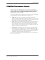
PCMCIA EXPANSION CARDS
Your QS7.1/QS8.1 is an expandable system. If you want access to more Sounds,
Programs, Mixes, Effects, and Sequences, all you have to do is pop the appropriate
memory card into one of the two [PCMCIA EXPANSION CARD] slots on the back
panel. Using both slots you can add up to 16 megabytes of memory, effectively
doubling the power of your instrument.
There are three different kinds of memory card that will work. All of them should
be available through your Alesis dealer (if not, call us). They are:
•
SRAM cards. Alesis offers a 512K SRAM card through our dealers that
provides an additional eight banks of Programs and Mixes. You can use and edit
these as you wish, or use the card as storage for your own creations. You can also
order a blank version of this card from us (part # 7-10-1203).
•
QCards. This is a series of ROM cards developed by us here at Alesis. Each is a
self-contained universe of new samples, plus Programs and Mixes designed to
take full advantage of them. Some of the cards available right now include
Classical, Sanctuary, Vintage Keyboards, Vintage Synthesizers, HipHop, and
EuroDance, with more coming out all the time.
•
FlashRAM cards. These are the cards you’ll need if you want to burn your own
custom sample cards. FlashRAM cards are available in 2MB, 4MB, and 8MB
sizes. Using Alesis’s Sound Bridge software (see Part 9: Extras) you can organize
all the necessary data on your PC or Mac and temporarily turn your QS into a
“RAMburner” when you are ready to make your own card.
Note: See the section entitled “Using PCMCIA Expansion Cards” in Part 9: Extras
for exact card specifications.
QS7.1/QS8.1 Reference Manual
29
First Session: Part 3
P ART 3
FIRST SESSION
P OWERING U P
Once your QS7.1/QS8.1 is connected to an audio system of some kind, you are ready
to play. Here’s how to begin.
1) Make sure that all connections have been made correctly, and that the volume
controls in your amplification system and QS are set to zero.
2) Throw the QS’s rear-panel [ON/OFF] switch to ON (the up position). The
display should light up and look something like this:
If this isn’t the first time your QS has been used, it may not say PROG in the
bottom left of the display. Press the [PROGRAM] button once to change that.
3) Push the [VOLUME] slider all the way up.
4) Turn on your amplifier or mixer, and gradually raise its volume while playing
your QS. When the sound is as loud as you want, stop.
P LAYING THE D EMO S EQUENCES
The QS has five built-in sequences designed to demonstrate its rich variety of
sounds and signal-processing effects. To hear these at their best, make sure to run
your QS in stereo (or else listen on headphones).
Please note: Your QS doesn’t send out MIDI messages during demo playback. In
addition, the keyboard is disabled. You can listen to the demos, but you can’t play
along with them.
•
To play all five sequences in order, hold down the [MIX] button and press [0].
When all five have played, your QS will exit DEMO mode on its own.
•
To stop the demos at any point during playback, press [MIX] again.
•
To play a specific demo, hold down [MIX] and press any of the five number
buttons from [0] through [4]. After a brief pause playback will start with the
demo you’ve selected, then continue through the remaining demos until done.
Note: After any of the demos stop playing, the QS will automatically return itself
to Program Mode. The next time you enter Mix Mode you will probably see the name
of the demo which was last played. This is because the Mix which was used for the
QS7.1/QS8.1 Reference Manual
29
Part 3: First Session
demo sequence remained in the Mix Mode edit buffers, which is normal. To clear
this, call up another Mix.
30
QS7.1/QS8.1 Reference Manual
First Session: Part 3
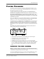
P LAYING P ROGRAMS
The mode in which your QS plays Programs is called, logically enough, Program
Mode. To enter it at any time, just press the [PROGRAM] button on the front panel.
Once there, all you have to do is play.
To explore different Programs in the current Bank, use the [SELECTION] and
[VALUE] buttons. Experiment with them until you have a feel for how they work.
Remember that the [VALUE] buttons move through the available Programs one at a
time, while the [SELECTION] buttons enable you to jump around at will — to get
Program 27 you would push [20] and then [7], to get Program 99 you would press [90]
and then [9], and so forth.
Please note: In MIDI there are no Program numbers above 127, so pressing [8] or [9]
after pressing [120] won’t do anything; and pressing [120] from any Program number
ending in 8 or 9 will “wall out” your Program choice at Program #127.
To explore Programs in a different Bank, use the [BANK] buttons. You can also get to
a new Bank by using the [VALUE] buttons to scroll from the end of one Bank to the
beginning of another, or vice-versa. (This means that if you are at Program 127 in
the Preset1 Bank, and press [▲ VALUE], you will jump to Program 00 in the Preset 2
Bank.)
The number, name, and Bank of the current Program will be visible in the LCD
display, which should look something like this:
•
The big numerals on the left show you the number of the current Program.
•
The upper line spells out the current Program’s name.
•
The middle line identifies the current Bank.
•
The PROG beneath the Program Number shows you are in Program Mode.
•
The small number underneath the Bank listing shows the current MIDI channel.
It is also a MIDI activity indicator, flashing a small circle whenever MIDI
data is sent or received over this channel. (To see this for yourself, hit any
key.)
CHANGING THE MIDI CHANNEL
MIDI has 16 channels. While in Program Mode, your QS can transmit and receive
information on only one of them. As noted just above, the current channel is shown by
a small indicator along the bottom of the LCD display.
To change this MIDI channel setting, press either of the the [PAGE] buttons on the
front panel until the MIDI channel number you want is visible in the display.
QS7.1/QS8.1 Reference Manual
31
Part 3: First Session
P LAYING M IXES
In Program Mode you play Programs, so to play Mixes you can probably guess that
you’d have to be in Mix Mode. To enter this mode at any time, just press the [MIX]
button on the front panel.
The display should look something like this:
As you can see, there are only two visible differences between this and the Program
Mode display:
•
The mode indicator in the lower left of the display reads MIX.
•
More than one MIDI channel is indicated. The numbers you see here tell you
what MIDI channels are being used to send and/or receive in this Mix. (This
also gives you a quick way of seeing how many Programs are in a particular
Mix, since the nature of Mixes is to have one Program per enabled MIDI
channel.)
PICKING A MIX BANK
Mixes come in Banks, just like Programs. In fact, they come in exactly the same
Banks — the only difference is that there are 100 Mixes in each Bank, as opposed to
128 Programs.
To cycle through the available Banks, get into Mix Mode and press the [BANK]
buttons as described earlier.
SELECTING MIXES
This works as described earlier for Programs; you’re just in a different Mode when
you do it. Start by making sure you are in Mix Mode, then use the [VALUE] keys and
[SELECTION] buttons to call up the Mix of your choice.
Please note that there are only 100 Mixes (numbered 00 through 99) in each Bank.
This is why pressing the [100], [110], and [120] selection buttons while you are in
Mix Mode won’t have any effect.
32
QS7.1/QS8.1 Reference Manual
First Session: Part 3
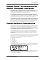
FINDING OUT WHAT PROGRAMS ARE
IN THE MIX YOU ARE PLAYING
It’s easy to see what Programs are currently assigned to the active MIDI channels in
a Mix. Just enter Mix Mode, call up the Mix you want to examine, and then move
through its MIDI channels using the [PAGE] buttons. Do that and the display will
change to look something like this:
There are five differences between this and the normal Mix Mode display:
•
The upper line shows the Program assigned to the current MIDI channel. This
name always appears inside quotation marks, so you can tell at a glance that
you are not in standard Mix Mode.
•
The upper line shows this Program’s number.
•
The middle line shows the Bank that the identified Program belongs to,
instead of the Bank that the Mix is in. As you will see when you examine
enough different Mixes, Programs can come from any Bank at all. You aren’t
limited to working just from those within the same Bank as your Mix. This is
wonderfully useful, but has some wrinkles you’ll need to be aware of if you ever
create Mixes using Programs stored on Expansion cards. (We’ll cover those issues
in more detail in Part 4: Basic Operation., Part 7: Editing Mixes, and Part 9:
Extras.)
•
The mode indicator beneath the Program Number now reads MIXPROG.
•
The current MIDI Channel Number will be flashing.
You can also change Program assignments from this display, but don’t try that just
yet. We’ll cover that fully in the next section, Part 4: Basic Operation.
Don’t be confused by the fact that you can use the [PAGE] buttons to look at all 16
MIDI channels in a Mix, even if those channels aren’t actually enabled. The only
channels that matter are the ones whose numbers are visible across the bottom of
the display when you first call up the Mix.
And now, just for fun…
QS7.1/QS8.1 Reference Manual
33
Part 3: First Session
T HE P ERFORMANCE C ONTROLS, P T. II
We described these real-time controllers in Part 2: Overview. Now that you know
how to find your way to all the different Programs and Mixes, it’s time to explore
just what the controllers can do.
Your assignment: Call up a Program or a Mix and try out the items listed just below.
When you think you’ve got a sense of how they work (or don’t) with your current
choice, call up a different Program or Mix and try them again. As you move around
you’ll see some interesting variations!
Here ‘s the list, as a reminder.
•
Velocity.
•
Aftertouch.
•
Pitch Bend Wheel.
•
Modulation Wheel.
•
Controller A–D Sliders.
•
Sustain Pedal.
•
Expression Pedals.
T RANSPOSING T HE K EYBOARD
One of the great conveniences of electronic keyboards is how easily they can be
transposed, allowing you to play all possible keys (even the more difficult ones)
without having to learn as many different fingerings and hand positions.
Just to round things out before we move on, why not experiment with your QS’s
Performance Transpose feature?
All you have to do is:
1) Hold down the [TRANSPOSE] button.
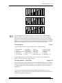
2) Tap the key that represents the interval you’d like to shift by. If you want to
shift up a semitone, for example, you would tap any C-sharp on the keyboard
that lies above Middle C. And if you want to shift a major third down, you’d
press any G-sharp below Middle C. See the chart on the next page for further
guidance.
3) Now let go of the [TRANSPOSE] button.
It’s that simple. Try it and see for yourself. When you finally want to return things
to normal, just hold down [TRANSPOSE] again and tap on the MIDDLE C key
before letting go.
You can go up or down as much as an octave, giving you a total of two octaves of
transposition range.
This technique gives you a quick way to make transpositions “on the fly.” You can
also transpose your QS using one of the Global commands. That works just a little
differently, and will be covered in the next part of this manual.
34
QS7.1/QS8.1 Reference Manual
First Session: Part 3
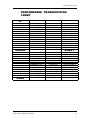
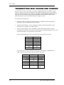
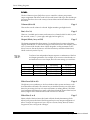
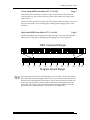
PERFORMANCE TRANSPOSITION
CHART
UP
OCTAVE
MAJOR SEVENTH
MINOR SEVENTH
MAJOR SIXTH
MINOR SIXTH
PERFECT FIFTH
DIMINISHED FIFTH
PERFECT FOURTH
MAJOR THIRD
MINOR THIRD
MAJOR SECOND
MINOR SECOND
+ 12 semitones
+ 11 semitones
+ 10 semitones
+ 09 semitones
+ 08 semitones
+ 07 semitones
+ 06 semitones
+ 05 semitones
+ 04 semitones
+ 03 semitones
+ 02 semitones
+ 01 semitone
NORMAL
C above Middle C
B above Middle C
B-flat above Middle C
A above Middle C
G# above Middle C
G above Middle C
F# above Middle C
F above Middle C
E above Middle C
D# above Middle C
D above Middle C
C# above Middle C
Middle C
MINOR SECOND
MAJOR SECOND
MINOR THIRD
MAJOR THIRD
PERFECT FOURTH
DIMINISHED FIFTH
PERFECT FIFTH
MINOR SIXTH
MAJOR SIXTH
MINOR SEVENTH
MAJOR SEVENTH
OCTAVE
- 01 semitone
- 02 semitones
- 03 semitones
- 04 semitones
- 05 semitones
- 06 semitones
- 07 semitones
- 08 semitones
- 09 semitones
- 10 semitones
- 11 semitones
- 12 semitones
B below Middle C
B-flat below Middle C
A below Middle C
G# below Middle C
G below Middle C
F# below Middle C
F below Middle C
E below Middle C
D# below Middle C
D below Middle C
C# below Middle C
C below Middle C
DOWN
QS7.1/QS8.1 Reference Manual
35
Basic Operation: Part 4
PART 4
BASIC OPERATION
R ECAP
At this point you’ve pretty much learned everything there is to know about how to
play your QS7.1/QS8.1:
•
You’ve got it hooked up and amplified.
•
You know about Banks, and how to switch among them.
•
You know about Programs and Mixes, and how to call them up.
•
You know how to use the real-time performance controllers.
•
You know about the various types of PCMCIA expansion cards, and how to plug
them in as sources for additional Banks of Programs and Mixes.
That’s quite a lot, actually. Add in a few more basics and some MIDI info (see Part
5: MIDI) and those of you who aren’t interested in editing anything in your
instrument will be set.
Ready? In this section of the manual we’ll give you those remaining non-MIDI
basics. They include copying Programs and Mixes to new locations in the User Bank
(or a Card Bank), renaming copied Programs and Mixes, changing the Programs
assigned to a Mix, playing Sequences from memory cards, and everything you need
to know about your QS’s Global settings.
But before we get started, there’s something we think you ought to know:
THE DOUBLE-BUTTON PRESS TRICK
There’s a pretty nifty hidden trick in the QS’s operating system. It’s called the
“Double-button press”, and what it does is reset certain parameters or functions back
to a certain value without you having to actually push those same buttons a bunch
of times to get there. It works with the [VALUE] buttons, the [PAGE] buttons, and
the [BANK] buttons.
Here are the areas where this trick is useful:
• If you press both [VALUE] buttons at the same time while you’re in one of the Edit
Modes (Program, Mix, Effects or Global), the value which is currently displayed
will change to the factory default for that parameter. This works in Store Mode,
too!
• If you press both [PAGE] buttons at the same time while you’re in one of the Edit
Modes, the Page which is currently displayed will change to the first page in
whatever Function you’re working with. This one also works in Store Mode.
• If you press both [PAGE] buttons at the same time while you’re in Mix Program
Select mode or Program Play mode, the QS will jump to MIDI channel 1.
QS7.1/QS8.1 Reference Manual
35
Part 4: Basic Operation
• If you press both [BANK] buttons while you’re in Mix Play or Program Play modes,
the QS will jump to the same location in the User bank.
36
QS7.1/QS8.1 Reference Manual
Basic Operation: Part 4
COPYING EXISTING PROGRAMS A ND
MIXES T O A N EW LOCATION IN T HE
U SER B ANK
You can readily move copies of existing Programs and Mixes into the User Bank.
This is useful if you want to put them in a certain order for recording or performance,
or to arrange interesting starter materials in preparation for editing.
The procedure is an easy one.
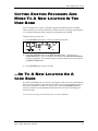
1) Press [STORE]. The display will look something like this:
2) Using the [VALUE] buttons or the [EDIT VALUE] slider — also known as
[CONTROLLER D] — pick a User Bank location between 000 and 127 (00 and 99
in the case of Mixes). You can also directly enter the number you want using the
23 [SELECTION] buttons.
3) Press [STORE] again, and you’re done.
…OR T O A N EW LOCATION ON A
CARD B ANK
If you have an SRAM card, you can move a Program or Mix to any one of the banks on
the card. The procedure is the same as listed above for copying a single Program or
Mix to the User Bank, except that in step 2) you would use the [BANK] buttons to
select a Card bank as your destination instead of the User bank. Everything else
works the same.
For more about working with SRAM cards, see Part 9: EXTRAS.
QS7.1/QS8.1 Reference Manual
37
Part 4: Basic Operation
CHANGING T HE PROGRAMS IN A M IX
This is actually the first level of editing for Mixes, but that’s okay — it’s an easy
and useful thing that you can do whenever you are in Mix Mode…and best of all you
don’t need to know anything special to do it!
1) Get into Mix Mode by pressing the [MIX] button.
2) Press either of the [PAGE] buttons and look at the display. One of the MIDI
channel indicators on the bottom line should be flashing, and the upper line
should now show a Program Name and Number. This Program is the one
currently associated with the flashing MIDI channel.
3) Use either the [VALUE] buttons or any of the 23 [SELECTION] buttons to call up
a different Program. You can also call up Programs from other Banks by using
the [BANK] buttons. The upper line of the display will change to show you
which Program you’ve selected for that MIDI channel.
4) Do this until you like what you’ve got.
5) If you want to change Program assignments for another MIDI channel, use the
two [PAGE] buttons to move around among the 16 channels that are available.
To stop editing and return to normal operation, press either [MIX] to go to Mix Mode,
or [PROGRAM] to return to Program Mode.
Note: Your QS will let you change Program assignments on all 16 MIDI channels,
even ones that aren’t yet enabled in this Mix. You won’t hear the changes you make
to a channel that isn’t yet enabled. That’s all right. If you want you can always go
ahead and make the assignments you want now, and enable their MIDI channels
later.
STORING A LTERED M IXES T O T HE
U SER B ANK (OR T O A C ARD )
This works just like copying, which was described a little earlier. A recap: Once
you’ve come up with a new combination of Programs that you like, press [STORE]
while still in Mix Edit Mode. Select your target bank and any number between 00
and 99 (using the usual methods), then press [STORE] again and you’re done.
STORING A LTERED PROGRAMS T O T HE
U SER B ANK (OR T O A C ARD )
This works just like copying, which was described a little earlier. A recap: Once
you’ve come up with a new combination of Sounds that you like, press [STORE]
while still in Program Edit Mode. Select your target bank and any number between
000 and 127 (using the usual methods), then press [STORE] again and you’re done.
38
QS7.1/QS8.1 Reference Manual
Basic Operation: Part 4
CHANGING T HE NAME OF A P ROGRAM
OR MIX
Call up the Program or Mix whose name you wish to change. Make sure it is visible
in the display, and then:
1) Press [EDIT SELECT].
2) Press [120], which calls up the NAME function while editing. The name you
wish to edit will appear, inside quotation marks, in the middle line of the
display. One of the characters in the name will be underlined (probably the
first one, if this is your first time naming something). Pressing both [PAGE]
buttons at the same time will take the cursor back to the first character, if
that’s the one you want to change.
3) Change the underlined letter by moving the [EDIT VALUE] slider or pressing
the [VALUE] buttons.
4) Move the cursor back and forth among the available spaces by pressing the
[PAGE] buttons. Change any or all of the characters as you wish.
5) When you are done — there is a 10-character limit — go through the steps
described above to store the newly named Program or Mix somewhere. Then
press either [PROGRAM] or [MIX] to leave this mode.
COMPARE M ODE
The [ BANK] button doubles as the [COMPARE] button (note the silkscreening on
the panel under the button). It allows you to go back and forth between the edited
version and the original version of a Program or Mix before committing yourself to
storing it.
Once a Program or a Mix have been edited, the word “EDIT” will change to
“EDITED” in the lower-left corner of the display. If [COMPARE] is pressed while
in an Edit Mode, you’ll see the word “EDIT” start flashing. If you play the QS
while it is doing this, you will temporarily be hearing (and seeing) the original
version of the Mix/Program. If you are editing a Mix and press [COMPARE], the
original unedited Mix is temporarily recalled. Likewise, if you are editing a
Program or its Effects Patch and press [COMPARE], the original Program will be
temporarily recalled. Pressing [COMPARE] again switches back to the edited
version, and the word “EDIT” will revert back to “EDITED” in the display.
QS7.1/QS8.1 Reference Manual
39
Part 4: Basic Operation
PLAYING SEQUENCES F ROM A C ARD
[This section assumes that you have some PCMCIA Expansion Cards with sequences
on them. If you don’t, you can move on and come back to this section later.]
Several of the Alesis QCards come with their own demonstration sequences. More
importantly, you can store your own MIDI sequences to RAMcards (in Standard
MIDI File format) using a computer and Alesis’s free Sound Bridge software, and
then play them back easily from your QS.
Here’s all you have to do.
1) Insert the RAMcard containing sequence data into either of the two [PCMCIA
EXPANSION] slots on the back panel of your QS.
2) Press the [SEQUENCE] button. The display will look like this:
3) Use the [SELECTION] buttons to pick the Card and Sequence Bank that holds
the sequence you’d like to play: the [00] through [40] buttons select Sequence
Banks 0-4 on Card A, while [50] through [90] select the equivalent Sequence
Banks on Card B.
4) Finally, use the [0] through [9] buttons to activate a specific sequence from the
selected Sequence Bank (each Bank can hold 10 sequences).
If there is a sequence there, just wait a moment and it will play. (A blinking right
arrow will show up in the display during playback.) If there isn’t a sequence there,
then the display will tell you so.
To stop a sequence while it’s playing, you can press your choice of the [SEQUENCE],
[PROGRAM] or [MIX] buttons. To leave this Mode and return to where you started
without triggering a sequence, press [SEQUENCE] again.
40
QS7.1/QS8.1 Reference Manual
Basic Operation: Part 4
T HE G LOBAL SETTINGS
(A ND HOW T O CHANGE T HEM )
Certain basic parameters affect your entire QS. Because they affect everything,
they are called the Global Settings. There are 19 of them:
GLOBAL EDIT PAGE
01
02
03
04
05
06
07
08
09
10
11
12
13
14
15
16
17
18
19
QS7.1/QS8.1 Reference Manual
GLOBAL SETTING
Master Pitch
Master Tune
Keyboard Velocity Curve
Keyboard Velocity Scaling
Transpose
Keyboard Mode
General MIDI
Controller A #
Controller B #
Controller C #
Controller D #
Pedal1 Control #
Pedal2 Control #
MIDI Program Change Mode
Input/Output Mode
MIDI Out Mode
Reset Controllers A-D
Controller A-D Mode
Clock Source/Rate
41
Part 4: Basic Operation
EDITING GLOBAL PARAMETERS
To enter Global Edit Mode:
1) Press [EDIT SELECT].
2) Press the [BANK ] button (that’s the one that has GLOBAL written beneath
it). The display will look like this:
Now look in the upper right corner of the display. There you will see an indicator
that says P1. This stands for Page One, and it tells you where you are among the 19
possible Global parameters. (Naturally enough, since there are 19 parameters
there are also 19 separate pages.)
•
To move around inside Global Edit Mode, you’ll use the [ PAGE] and [PAGE ]
buttons. These cycle you through all the available pages and their associated
parameters. (Try it and you’ll see that the page indicator changes as you go.)
•
To change the settings you see in the Global Edit pages, use either the [D] slider
(the one with EDIT VALUE written under it) or the two [VALUE] buttons.
•
To leave Global Edit Mode, press either [MIX] (to return to Mix Mode) or
[PROGRAM] (to return to Program Mode).
You can also shift directly from setting Global parameters to editing either
Programs or Mixes by pressing one of the 23 [SELECTION] buttons. But that’s for
later in this manual. Right now, we want to stick to Global changes only.
PAGE 1 — MASTER PITCH
As you can probably guess from its name, this setting controls the Master Pitch of
your QS. Adjust this parameter when you wish to globally transpose all sounds
played by the QS, whether from the keyboard or by incoming MIDI information.
This parameter does not change the pitch of drum sounds (but see note below). It
also has no effect on the Range settings in Mixes and Programs, or on what note data
gets sent from the QS’s MIDI Out when you play the keyboard.
The range for this setting is –12 to 12, which is equivalent to down or up by one
octave (in semitones).
Note: Changing MASTER PITCH can alter QS drumkits in unpredictable ways,
because it shifts the key assignments of multi-sampled drumkits in Keyboard Mode
but doesn’t shift Drum Mode sounds. Most Preset drumkits are constructed using a
combination of the two. (For an explanation of Drum Mode, see Part 8: EDITING
PROGRAMS.) This goes for incoming MIDI notes as well as notes played on the
keyboard, so your drum parts will play back differently than you laid them down
if you alter Master Pitch after recording. If you want to explore these changes, go
ahead — you can always return things to normal by setting MASTER PITCH back to
00.
42
QS7.1/QS8.1 Reference Manual
Basic Operation: Part 4
PAGE 2 — MASTER TUNE
This setting is like Master Pitch, but on a much finer scale. Its main use will be to
tune your QS to match other instruments. (If you are playing along with an acoustic
piano that is consistently a little sharp or flat, for example, it’s a lot easier to
tweak this setting than to call in a piano tuner!)
Like Master Pitch, Master Tune has no effect on Drum Mode sounds, Range settings,
or the note data sent from the instrument’s MIDI Out. But it does affect multisampled drumkits from Keyboard Mode (see note).
The range for this setting is –99 to 99. This is equivalent to down or up one half-step
(in hundredths of a semitone).
Note: Drumkit time again. This parameter does not have any effect on Drum Mode
sounds. However, it will work to tune drums that are part of multisampled
Keyboard Mode drumkits. What happens is that they tune down or up as far as
they can go and then switch to the next keygroup, which will probably be a
different sample.
PAGE 3 — KEYBOARD VELOCITY CURVE
This parameter alters the “feel” of your QS’s keyboard playing response. There are
three options:
WEIGHTED gives the keyboard the widest possible dynamic range.
PLASTIC has the narrower dynamic range associated with typical synth
keyboards. You can still hit maximum volume with this setting, but notes played
gently will be louder than they would be if you had selected WEIGHTED. Use this
mode when you want a smoother, flatter keyboard response.
MAXIMUM means that every note played on the keyboard is given the maximum
MIDI velocity, which is 127. In this mode, your QS’s keyboard is no longer velocitysensitive. (Please note that while this affects the keyboard and any note data
being sent from your QS, it has no impact on how incoming MIDI note data is
processed. Altering that is done on a Program by Program basis, using the Velocity
Curve parameter available in Program Edit Mode.)
PAGE 4 — KEYBOARD VELOCITY
SCALING
This parameter also alters the “feel” of your QS’s keyboard, but in a different way
than the Keyboard Velocity Curve setting mentioned just above. Unlike that
setting, it doesn’t alter the dynamic range. Instead it takes the existing velocity
curve and gives it a slight bias toward either soft or hard styles of playing.
Here’s how it works. The range for this setting is 00 to 99. When set to 00, it scales
the keyboard velocity data so that loudness increases more slowly than usual as
you play harder. At 00 it is a little easier to play quietly and a little harder to
play loud. Push this setting all the way up to 99 and you get the opposite: keyboard
velocity is scaled to make it easier to play loud, while playing soft will require
great finesse.
QS7.1/QS8.1 Reference Manual
43
Part 4: Basic Operation
The factory default setting is 65, which gives an even scaling that favors neither
loud nor soft playing. You will need to experiment with this parameter to find
exactly the right adjustment for your own “touch.”
PAGE 5 — TRANSPOSE
This is the same Transpose setting you were introduced to in Part 3: First Session.
The only difference is that in Global Edit Mode you make changes using the
standard [EDIT VALUE] slider and [VALUE] buttons, not by pressing keys on the
keyboard.
The transposition range is from –12 to 12, which is the same as moving down or up by
semitones over a two-octave range. It works by changing the MIDI Note Numbers
assigned to the keyboard, thus changing the note data sent out from your QS when
you play.
So, if you want to play notes that are outside the QS’s normal 61-note range (MIDI
Note Numbers 36-96), then by all means transpose! Taken down an octave, the
keyboard’s range becomes MIDI Note Numbers 24-84; taken up an octave, it covers
MIDI Note Numbers 48-108.
This is very useful knowledge if you are using your QS to play music into a
sequencer, since this parameter gives you two extra octaves of keyboard recording
range.
PAGE 6 — KEYBOARD MODE
There are three possible keyboard modes. Which one you want to use will depend on
how you are using your QS:
NORMAL is the default setting. When NORMAL is selected, Program Mode
receives and transmits over the MIDI channel indicated in the display. In Mix
Mode, MIDI information is received over all active MIDI channels, but sent only
from those displayed channels that have had MIDI OUT enabled. The MIDI
Channel indicators in the lower line of the display will show which channels are
active at any given time.
CH SOLO changes the way the keyboard handles MIDI in Mix Mode (it has no
effect on Program Mode). The simplest way to describe what it does is to say that it
isolates individual channels in a Mix, allowing you to play only the selected
channel (indicated by a flashing number in the display) from the keyboard, while
ignoring all the Programs assigned to other channels. This is a great way, for
example, to individually check out the different Programs that are in a layered
Mix. And since CH SOLO has no effect on incoming MIDI data, it’s a great mode for
sequencing. You can just move through your multi-timbral Mix one channel at a time,
recording on single channels as you go while always hearing playback on
everything that you’ve already laid down. (If you’ve selected CH SOLO, the
[ PAGE] and [PAGE ] buttons are what you’d use in Mix Mode to hear each
channel in turn.) When using CH SOLO, make sure you turn off your sequencer’s
ECHO function (sometimes called SOFT THRU or THRU). More about this sort of
thing in Part 5: MIDI.
Note: This mode is automatically selected by the QS when the General MIDI
function is set to ON.
44
QS7.1/QS8.1 Reference Manual
Basic Operation: Part 4
OUT 01 through OUT 16 select a single MIDI channel to transmit on, while
simultaneously shutting off local keyboard control. You’ll want to choose this
setting if you are using a sequencer that automatically echoes back the MIDI data
that is being recorded. (If your sequencer works that way and you don’t choose one of
the OUT settings, you will run out of available Voices faster as the echoed notes
double what you are playing.)
✪
Setting the Keyboard Mode to one of the OUT values is the QS’s equivalent to
LOCAL OFF.
PAGE 7 — GENERAL MIDI
This parameter turns General MIDI Mode on and off. You’ll want to set it to ON if
you are going to use your QS to play back sequences created specifically for use with
a General MIDI module. Otherwise you’ll want to leave it alone.
For more information about General MIDI, see the MIDI supplement in Part 10:
Appendices.
WARNING: Do not change this setting to ON unless you really mean to. Why?
Because doing so will immediately take you out of Global Edit Mode, switch to Mix
Mode, and call up the GM Multi Mix (Mix 00 in Preset Bank 4, which is the General
MIDI Bank). This can be pretty darned confusing if you aren’t expecting it, but don’t
worry — it’s easy to return to Global Edit Mode and set this parameter back to OFF.
Some (but not all) General MIDI sequences will have a SysEx message at the
beginning which tells the receiving device to go into General MIDI mode. The QS
will respond to such a message. If one comes in, then your instrument will
immediately jump from wherever it is to the GM Multi Mix.
The General MIDI spec reserves MIDI Channel 10 for drumkits. Because of this,
when the global General MIDI setting is ON, your QS won’t be able to call up
anything but drumkits on Channel 10 (from the front panel or via MIDI).
Note: Turning General MIDI mode ON also automatically sets your Keyboard Mode
to CH SOLO. Turning General MIDI off will put the Keyboard Mode back the way
it was. Also, see the Note under Global Page 14.
PAGE 8 — CONTROLLER A #
This parameter lets you select the MIDI Controller Number that will be assigned to
the front panel’s [CONTROLLER A] slider. This is useful both for controlling
external MIDI devices and for giving you sequencer-recordable control over a
variety of Program and Effect parameters. The factory default is Controller 012.
For a listing of all MIDI controllers and their designations, see the MIDI
Supplement section of Part 10: Appendices.
PAGE 9 — CONTROLLER B #
QS7.1/QS8.1 Reference Manual
45
Part 4: Basic Operation
The same as Global Edit Page 8, above, but for Controller B. The factory default is
Controller 013.
46
QS7.1/QS8.1 Reference Manual
Basic Operation: Part 4
PAGE 10 — CONTROLLER C #
The same as Global Edit Page 8, above, but for Controller C. The factory default is
Controller 091.
PAGE 11 — CONTROLLER D #
The same as Global Edit Page 8, above, but for Controller D. The factory default is
Controller 093.
PAGE 12 — PEDAL 1 CONTROL #
Just like MIDI Controllers A–D, your QS’s [PEDAL 1] jack can be assigned to a MIDI
controller. In fact, it already is. The factory default is Controller 007 (Main
Volume), which explains why a pedal plugged into the back panel’s Pedal 1 jack
will automatically control volume.
It doesn’t have to be limited to that, however. You can use this parameter to change
it to any Controller from 0 to 120. (Please note that if you do, a footpedal plugged
into your [PEDAL 1] jack won’t work as a volume control anymore!)
In short, then, this setting determines what MIDI data is sent out when you step on
a properly-connected footpedal. And since PEDAL 1 is also an available setting for
modulating Programs or Effects, your choice here will determine exactly what
incoming MIDI Controller data will modulate those Programs, Effects and (by
extension) Mixes that have been set up to respond to PEDAL 1.
Something to be aware of: Unless you deliberately mean to, don’t assign the same
Controller Number to two different physical controllers. Their interaction could get
very confusing! It’s even possible that they could fool you into thinking that
something in your QS is either broken or not working properly, since you’d be moving
a controller and not getting the exact response you expect.
PAGE 13 — PEDAL 2 CONTROL #
This setting works exactly like Pedal 1, just above.
If you don’t have a second pedal, you can still use this function in a very powerful
way. This Global page gives you one more assignable continuous controller to which
the QS can respond. Also, when you get to Part 8: Editing Programs, you will see
that PEDAL 2 is one of the available Program modulation sources. So you can plug
in a second pedal and control any number of Program or Effects modulation
destinations, or you can simply allow the MIDI controller of your choice to do it for
you.
The factory default for this setting is 004 (Foot Controller).
QS7.1/QS8.1 Reference Manual
47
Part 4: Basic Operation
PAGE 14 — MIDI PROGRAM SELECT
MODE
This parameter determines how your QS deals with MIDI Program Change
Commands. There are three possible settings:
OFF turns all Program Changes off. With this choice selected, your QS will
neither send Program Changes nor respond to them.
ON makes the QS respond to incoming MIDI Program Changes, and send them out
whenever you change Programs from its front panel. In Program Mode it will send
and receive Program Changes over the currently selected MIDI channel. In Mix
Mode, Program Changes are received over all active MIDI channels, but sent only
from those displayed channels that have had MIDI OUT enabled. Please Note:
With this setting, incoming Program Changes will only affect the Programs
associated with each specific channel, not the entire Mix.
MIDI MIX SELECTION: CHANNEL 1 through CHANNEL 16 are identical to ON
as far as Program Mode is concerned. In Mix mode they work quite differently,
however, allowing you to change entire Mixes in response to Program Change
commands. Select CHANNEL 4, for example, and a Program Change 22 command
coming in over MIDI Channel 4 would automatically select Mix 22 in the current
Bank. The same is true of Bank Select messages which come in on Channel 4 in this
scenario; they’ll call up a Mix in another Bank. (Program Changes coming in over
other MIDI channels would continue to work as before, changing any Programs
associated with those channels within the current Mix.)
Any time you turn General MIDI Mode (Global Page #7) to ON, the MIDI Program
Change setting will automatically default to ON as well. There’s a good reason for
this: if MIDI MIX SELECTION were left in place here, then an incoming Program
Change could call up some other Mix than the standard GM Multi Mix…and there’d
be no telling what the GM sequence you were playing might wind up sounding like!
For an in-depth discussion of how these settings impact Bank Select transmission
and response, see Part 5: MIDI.
PAGE 15 — INPUT/OUTPUT MODE
This parameter determines whether your QS will communicate to the outside world
through (A) its MIDI jacks, or (B) its serial port. The possible selections depend on
how the rear panel [SERIAL PORT SWITCH] is set.
1) If the switch is set to MAC, your choices will be MIDI and MAC 1MHz.
2) If it is set to PC, your choices will be MIDI, PC 38.4kBaud, and PC 31.25kBaud.
(Your typical PC will work properly at the 38.4kBaud setting. PCs that require
the 31.25kBaud setting are quite rare.)
If you select MIDI, then the MIDI jacks will work and the serial port won’t. This is
the factory default.
Select any of the others and you’ll get the opposite result: the serial port will be on
and the [MIDI IN] and [MIDI OUT] jacks will be shut off (although the MIDI OUT
jack can still be used as a MIDI THRU depending on the MIDI Out Mode setting
described just below).
48
QS7.1/QS8.1 Reference Manual
Basic Operation: Part 4
PAGE 16 — MIDI OUT MODE
In normal MIDI operation, this parameter lets you switch the function of the back
panel [MIDI OUT] jack between being a MIDI OUT and being a MIDI THRU. Given
that, the two possible settings — OUT and THRU — should be self-explanatory.
The factory default is OUT.
If, however, you have selected one of the SERIAL PORT settings instead of MIDI
(as discussed just above) then your choices become OFF and THRU, with OFF as the
default.
When this setting is OFF, the [MIDI OUT] jack doesn’t send any data to external
devices. Change it to THRU and the jack will automatically echo any MIDI data
coming into your QS over the serial connection.
In some situations you may need a direct serial link to a computer and a normal
MIDI OUT running from your QS to other instruments. Here’s the solution: Set the
MIDI Out Mode to THRU and then turn on your computer’s MIDI THRU function.
This will echo any incoming QS data back to your keyboard, which will echo it in
turn to the [MIDI OUT] jack that is operating as a MIDI THRU. The net result will
be the same as if a normal MIDI OUT was in place.
PAGE 17 — RESET CONTROLLERS A-D
This parameter determines whether the values for Controllers A–D will (A) reset
to zero or (B) stay the same whenever a new Program or Mix is chosen. The factory
default is ON, which is the setting that forces a reset whenever you change from
one Program or Mix to another. The other possible setting is OFF.
Which one makes the most sense will depend on what you are trying to do.
For example:
If you were using [CONTROLLER] sliders to affect the volumes of external MIDI
sound modules, you’d probably want to set this parameter to OFF. That way you
wouldn’t reset all the different modules to zero volume every time you changed
Programs.
On the other hand, if you were using the [CONTROLLER] sliders to modulate
various Program parameters, then you might very well want to set this parameter
at ON in order to maintain a smooth continuity of control as you move among
different Programs and Mixes.
PAGE 18 — CONTROLLER A-D MODE
This parameter determines how the data generated by moving Controllers A-D
will be used. There are three possible settings:
LOCAL sets things so that your [CONTROLLER] sliders work with your own QS, but
do not generate any MIDI data.
MIDI does the exact opposite. Select this, and your [CONTROLLER] sliders will
send out MIDI data but have no effect on your own QS Programs and Mixes.
QS7.1/QS8.1 Reference Manual
49
Part 4: Basic Operation
BOTH sets the sliders up so they control your QS and send MIDI data. This is the
factory default setting.
PAGE 19 — CLOCK SOURCE/CLOCK RATE
This parameter determines the “sample playback rate” which the QS will use. If
you’re not using the QS’s digital audio output to send the signal from your QS to
some other piece of gear, you should leave this parameter alone.
But if you are using the digital audio output capability of the QS, then you will
find this page of the Global Edit Mode to be very useful. There are four different
settings here: Int 48kHz (the default), Int 44.1k, Ext 48kHz and Ext
44.1k.
The concept of a “clock rate” is based upon the fact that every sound inside the QS
is a digital recording of something. What a digital recording does is take a bunch of
“snapshots” of an audio signal. These “snapshots” are then played back in order to
reconstruct the original sound. The process is something like the relationship
between one frame from a videotape and the “playing back in order” of a bunch of
video frames in order to “recreate” the original scene.
And in the same way that the video frames blend together to create the perception
of motion, so the audio samples in the QS are played back so quickly and so
seamlessly that they appear to the human ear to be one sound. The rate at which
samples are played back is determined by the Clock function.
When set to either Internal setting, the QS uses its own internal sample clock as a
reference for playing back the sampled sounds in your Program or Mix. But in a
digital recording environment, it is often necessary for a piece or several pieces of
gear to be able to “turn over control” to one “master” clock signal, so that all of the
gear can play back their “snapshots” at the same rate.
Hence the “External” clock settings of the QS. Note that if you set the QS to one of
the two External clock settings without hooking it up to an external clock, it will
make a sort of “hissing” or “sprinkler” noise. This is because it is looking for
something to provide it with a clock signal and it isn’t finding it.
So here’s a brief rundown on when to use which setting:
Int48kHz. This is the default setting for the internal clock. It will have an almost
imperceptibly wider frequency response than 44.1 kHz. Use it if recording via the
QS’s digital output to an ADAT-XT which is using a sample rate of 48 kHz and
there is no Alesis BRC in the system.
Int44.1k. The one to choose if you are recording digitally to an ADAT-XT which is
using a sample rate of 44.1 kHz and there is no Alesis BRC in the system.
Ext48kHz. If you are recording to an ADAT-XT in the digital domain and are using
an Alesis BRC, connect a BNC-to-BNC cable between the BRC’s 48 kHz Clock Out
and the QS’s [48 kHz IN]. Then select the Ext48kHz setting for the QS’s clock
setting.
Ext44.1k. Same as above, but if the BRC has been set to 44.1 kHz (by having been
“Pitched Down” to -147), select the Ext44.1k clock setting for the QS.
50
QS7.1/QS8.1 Reference Manual
Basic Operation: Part 4
If you would like a visual aid for this, check out the Connection diagrams in
Chapter 1: Setups and Connections.
QS7.1/QS8.1 Reference Manual
51
MIDI: Part 5
PART 5
MIDI
WHAT WE’LL COVER HERE...
• Sequencing with the QS7.1/QS8.1 via MIDI or the serial port.
• Using the QS as a master MIDI keyboard for a live rig, along with a little more
info about controlling external MIDI devices from a Card sequence.
• Sys-ex transfers. How to go about transferring single Programs, Mixes or an entire
User bank via Sys-ex to a computer or another QS series synth.
…AND WHAT WE WON’T
(BUT WHERE YOU CAN FIND IT).
• How to create a Mix. We will go over selecting Programs within a Mix (the very
top level of Mix editing), but for information on things like setting levels or selecting
the Effects Patch within the Mix, see Part 7: Editing Mixes. Our main focus here will
be on interfacing the QS with the outside world.
• General MIDI (GM) will only receive a brief amount of coverage here, because it’s
covered pretty well in the discussion about Global Edit Mode’s page 7 (Part 4: Basic
Operation). There’s even more in-depth coverage of it in Part 10: Appendices
(Appendix B: MIDI Supplement).
• Basic MIDI concepts. If you’re a novice to the world of MIDI, you should make it a
point to read the MIDI Supplement in Appendix B soon. It’ll help things make a lot
more sense a lot sooner if you want to get a good handle on MIDI sequencing.
THE POWER OF MIX MODE
In Program Mode, the QS sends and receives MIDI information on only one MIDI
channel at a time. In Mix Mode, however, the QS can send and receive on as many as
16 MIDI channels at once, each with its own keyboard range and a whole lot of other
parameters you can customize. Mix Mode allows a single QS to play back full song
arrangements at one time, with full control over the levels and stereo placement of
the various Programs, complete with the Effects necessary to make the music shine.
But we also said it cansend (and how!). A QS in Mix Mode gives you the potential to
control a whole lot of other MIDI devices at one time. When the next song calls for
you to layer strings from that box with the brass from this box along with a couple of
internal Programs, mixed just so, while calling up the DMPro kit for the drummer,
setting the Q20 Reverb patch for the singer, and changing the setup on your lighting
controller, selecting a single Mix on the QS can do all of that. It’ll set up your whole
rig instantly, right before the next song is to begin (even if your band changes its
collective mind at the last second and starts a tune that wasn’t on the song list!).
We’ll dig into the MIDI controller aspects of the QS later in this chapter. For now,
let’s start talking about…
QS7.1/QS8.1 Reference Manual
49
Part 5: MIDI
USING AN EXTERNAL SEQUENCER
The QS can generate MIDI signals for a sequencer to record. On playback, the
sequencer sends this data back into the QS, which then serves as a multitimbral sound
module (in Mix Mode). The sequencer can generate data over several channels; in Mix
Mode, the QS can be programmed so that individual Programs play sequenced data
on specific channels. Example: If the sequencer transmits a piano part over channel 1, a
bass part over channel 2, and a drum part over channel 10, you could set up a QS Mix
so that a piano sound plays only the MIDI data coming in on channel 1, a bass sound
plays only the MIDI data coming in on channel 2, and drums play only the MIDI data
coming in on channel 10.
For this to happen, you have to connect the sequencer’s MIDI Out to the QS’s [MIDI
IN], and the QS’s [MIDI OUT] to the sequencer’s MIDI In. Also, in Global Edit mode,
page 15 (I/O) must be set to "MIDI". This allows the QS to send data to the sequencer
for recording, and play back data from the sequencer.
THE SERIAL PORT
All of the following information about sequencing with the MIDI ports applies to
operations with the serial port as well. The most obvious difference is that if you use
the built-in serial port you won’t need an additional MIDI interface.
If you already have the proper cables installed (and the Alesis serial driver, if you’re
using a PC-compatible computer), then you’re almost ready to begin. Read about
enabling the serial port in Part 1: Setup and Connections on page 14. You’ll also find
some very important information about using the serial port in conjunction with the
MIDI Output jack in Part 4: Basic Operation on page 47. Look for the section at the
bottom that goes over Global Edit mode pages 15 and 16.
Information about the Alesis Serial Driver and the cables you’ll need in order to do
this is also in Part 1: Setup and Connections on page 15.
50
QS7.1/QS8.1 Reference Manual
MIDI: Part 5
SELECTING THE KEYBOARD MODE
In a Mix, the QS’s keyboard may be set up in several ways using the Keyboard Mode
parameter found on Page 6 of Global Edit Mode. You need to determine which way
is best for your application. The Keyboard Mode parameter determines how the
keyboard will function with regard to MIDI:
•
OUT 01 – OUT 16. Use this mode if you’ll be sequencing parts for other MIDI
devices in addition to the QS. Select OUT 01, and the keyboard will send on only
MIDI channel 1 (or channel 2 if you select OUT 02, and so on). In this case the
sequencer must be used to set the MIDI channel of each track you want to record.
Note: With this mode selected you will not hear the QS unless your sequencer echoes
the MIDI data back to the QS’s MIDI IN. (This is also one way of verifying that
the sequencer is set to receive properly.) “Local” control of the QS is turned OFF
with this mode selected, so if things get disconnected somehow you won’t be
able to play anything from the QS’s keyboard. For example, this could happen if
you accidentally select the “desktop” on your computer, temporarily disabling
the sequencing application.
So be sure to set up your sequencer to “echo” the MIDI data back to the QS. You
can then set up the QS to pass the “auto-channelized” data along to other MIDI
devices by setting its MIDI Out Mode to Thru (Global Edit mode, page 16). If the
sequencing software is set up correctly, you’ll be able to play on a different MIDI
channel with each new track you record.
•
NORMAL. Use this mode if the Mix is split or layered and sending on many
MIDI channels at once, and the sequencer will be able to record all channels at
one time. Good for capturing live performances in Mix mode.
This will only work if you have MIDI Out enabled for every MIDI channel within
the Mix which you would like the sequencer to record. The MIDI Out parameter
is on page 2 of the KEYBOARD/MIDI function in Mix Edit Mode. Once you’re in
Mix Edit Mode, select the MIDI channel for which you would like to set this up
by pressing its [SELECT] button ([0] - [9] for channels 1-10, [00] - [50] for
channels 11-16).
•
CH SOLO. Use this mode if you’re sequencing with the QS alone (no external
MIDI modules). The keyboard only sends on one MIDI channel at a time, and
you change the channel on the QS for each separate track on the sequencer.
Naturally, this only works in Mix Mode, because Program Mode is kind of
already in Channel Solo mode by default.
This mode is automatically selected by the QS when the General MIDI function is
set to ON.
Note: In NORMAL or CH SOLO mode, the QS sounds are internally played from the
QS keyboard, so any echo features of the sequencer should be turned off.
QS7.1/QS8.1 Reference Manual
51
Part 5: MIDI
PROGRAM ASSIGN FOR EACH MIDI CHANNEL
Assign Programs to the 16 channels of the Mix by using the [ PAGE] and [PAGE
]
buttons to select a channel (the silkscreening also identifies those as the [MIX CHANNEL
PROGRAM SELECT] buttons). Then use the [0] – [9] and [00] – [120] buttons to select a
Program for that channel. If desired, you can use the [ BANK] and [BANK ] buttons to
select a Program from any of the internal or card banks.
SENDING AND RECEIVING BANK SELECT MESSAGES
The QS will send and respond to MIDI Bank Select messages in the form of MIDI
Controller 0. The value of Controller 0 determines which bank is to be recalled (User,
Preset 1–3, GenMIDI, CardA, Card B). A total of 11 banks are accessible between the
cards. The way the QS handles Bank Select messages depends on the MIDI Program
Select mode (Global Edit Mode, page 14):
MIDI PrgSl: OFF
The QS will neither transmit nor receive Bank Select messages or Program change
commands with this setting.
MIDI PrgSl: ON
Reception: Program Mode. If a Bank Select (controller 0) message with a value of 0 is
received, it will cause the User Bank to be recalled. If a Bank Select message of 1 is
received, Preset Bank 1 will be recalled. Additionally, if a Sound Card is inserted, the
Card Banks can be selected using Controller 0 values between 5 and 15. Values higher
than 15 are “wrapped around” and will start through the Banks order again. This
means that a Controller 0 message with a value of 16 or 32 will recall the User Bank,
while a value of 17 or 33 will call up Preset Bank 1.
Reception: Mix Mode. Same as above, except the Mix itself will not change Banks.
The word “EDITED” will appear in Mix Play mode screen, because the Mix has been
altered to point to another bank on one of its MIDI channels. But you have to look
inside the Mix to see that the Bank change occurred.
Transmission: Program Mode. If a new Bank is selected using the [BANK] buttons, a
Bank Change message will be transmitted. See Reception: Program Mode for a
description of which values will be sent for each Bank as it is selected.
Transmission: Mix Mode. If a new Bank is selected and any of the channels within
the Mix have their MIDI Out parameters set to ON (Mix Edit Mode, Keyboard/MIDI
function, Page 2), a Bank Select message (followed by a Program change) will be
transmitted for each of those MIDI channels.
In Mix Program Select Mode (where you choose the Programs within the Mix), any
channel which has its MIDI Out set to ON will transmit Bank and Program changes
from within the Mix, just like in Program Mode.
52
QS7.1/QS8.1 Reference Manual
MIDI: Part 5
MIDI MixSl: CH 1-16
Reception: Program Mode. Same as with MIDI PrgSl: ON (see above).
Reception: Mix Mode. In this mode, when a Bank select message is received on the
channel specified by this parameter, the Mix itself will change Banks. Any Program
change command on this same channel will call up an entire Mix as if it were a
Program. All other channels within the Mix will behave the same way they do when
MIDI PrgSl: ON is selected (i.e., they receive Bank and Program changes normally).
Transmission: Program Mode. Same as with MIDI PrgSl: ON (see above).
Transmission: Mix Mode. If a new Bank is selected, the Bank number of the Mix
itself will be transmitted on the channel specified by this parameter. Selection of
another Mix in the same bank will send a Program change command which matches
the Mix number.
In Mix Program Select Mode (where you choose the Programs within the Mix),
changing the Bank of any Program within the Mix will not send a Bank Select
command. Selecting a new Program within the Mix will not send a Program change
command.
Note: Bank change messages will be ignored if General MIDI Mode is enabled, so that
only Programs within the General MIDI Bank (GenMIDI) can be recalled via MIDI
Program changes. The MIDI Program Select parameter will automatically be set to
MIDI Prg: ON.
QS7.1/QS8.1 Reference Manual
53
Part 5: MIDI
USING THE QS AS A MASTER KEYBOARD
Mix Play Mode also allows the QS to function as a very powerful MIDI master keyboard.
You can layer the QS’s internal sounds with those of several external synthesizers by
adjusting the proper parameters in Mix Edit mode.
For instance: You probably already know that you can layer and/or split several QS
Programs in Mix Mode while simultaneously playing external synthesizers on those same
MIDI channels. But the real power comes from using QS MIDI channels which have their
Keyboard and MIDI Input parameters turned OFF. When this is the case, you can send a
combination of MIDI Program changes and MIDI volume and panning commands to the
external devices to select and blend them precisely the way you want with internal Programs
on other channels. What's more, the QS can transpose the outgoing MIDI note numbers so
you can play high octave brass sounds from an external device in the lower region of the
keyboard, and/or layer external mid-range pads with high QS strings in the upper region.
The QS is so versatile as a master keyboard that if you play live, it could prove indispensible.
Or if you just like having that huge, perfect, multi-MIDI-module stack for inspiration in your
studio, the QS will call it up for you just the way you want it every time.
There’s a detailed description of the parameters you would use to make all of this happen in
Part 7: Editing Mixes. If you haven’t read that chapter yet, go check out the section that
describes the KEYBOARD/MIDI function (button [90]). If you’re already familiar with those
parameters, you're not far from being able to do the things listed in the previous paragraph.
Note: Be sure to check out the following pages for some useful information regarding:
• Bank Select and Program changes (Part 5: MIDI, pages 52 and 53)
• Making sure the Effects Patch doesn’t change in a Mix when Program changes are received
(Part 6: Editing Effects, page 64)
• Enabling and disabling the Wheels, Aftertouch, Sustain Pedal, and Controllers
independently per channel (Part 7: Editing Mixes, page 105)
• Assigning different MIDI controller numbers to the four sliders and two variable pedal
inputs (Part 4: Basic Operation, pages 44 and 45). Remember that even if you’re not using pedals,
the controller numbers you assign to them are still available as Mod sources via MIDI.
• Setting up the A-D controllers so they either control internal parameters, send data
to MIDI, or both (Part 4: Basic Operation, page 47).
54
QS7.1/QS8.1 Reference Manual
MIDI: Part 5
MAKING IT HAPPEN
The three parameters found under the KEYBOARD/MIDI button determine how the QS will
function as a MIDI controller. For example:
• To play both an internal Program and an external MIDI sound source on a given channel,
set both the Keyboard parameter and the MIDI Output parameter to ON.
• To play an internal program from the QS's keyboard and not trigger an external MIDI
module on a given channel, set Keyboard to ON and MIDI Output to OFF.
• To play an external MIDI sound source but leave the QS silent on a given channel, set its
MIDI Output parameter to ON and its Keyboard parameter to OFF. But while you’re at it,
you may as well turn MIDI Input to OFF, because…
• To send volume, panning, and transposition information to an external MIDI sound source
on a given channel, set MIDI Out to ON and set both MIDI Input and Keyboard to OFF. This
is covered in greater detail on the next page.
Remember: This only works if that channel isn’t playing a QS Program.
Note: When using the QS for this sort of thing, be sure the Keyboard Mode is set to
NORMAL and the MIDI Program Select parameter is set to ON (Global Edit Mode,
Pages 6 and 14). For more information, see Part 04: Basic Operation. There’s also some
good stuff about setting the Keyboard mode in this chapter. Look for the section
called “Selecting the Keyboard Mode” under “Using an External Sequencer.”
QS7.1/QS8.1 Reference Manual
55
Part 5: MIDI
TRANSMITTING MIDI VOLUME AND PANNING
Each Channel in a Mix can transmit its volume and panning settings via MIDI. For each
channel on which you wish to transmit this data, MIDI Out must be set to ON and MIDI
Input and Keyboard must be set to OFF (as explained in the KEYBOARD/MIDI section on
page 102). Also, the Keyboard mode must be NORMAL and the MIDI Program Select
parameter must be set to ON (Global Edit Mode, Pages 6 and 14).
If a channel is set up this way:
•
whenever a Mix is recalled (via the front panel or via MIDI), volume and panning
information will be transmitted for that Channel;
•
whenever that Channel’s “Level” parameter is edited, volume information will be
transmitted as Controller #7 on that Channel;
•
whenever that Channel’s “Pan” parameter is edited, panning information will be
transmitted as controller #10 on that Channel. However, panning information will not be
sent if the Channel's "Pan" parameter is set to PROG.
The seven pan positions in a Mix send the following controller #10 values:
Mix Pan value CC#10 value
3>
127
2>
107
1>
85
<>
64
<1
43
<2
21
<3
0
Conversely, if you want to change the panning of a QS Program via MIDI, here is
what you'll get if you transmit a given controller #10 value:
CC#10 value Mix Pan value
0-20
<3
21-42
<2
43-63
<1
64-84
<>
85-106
1>
107-126
2>
127
3>
56
Placement
(hard left)
(mid left)
(soft left)
(center)
(soft right)
(mid right)
(hard
right)
QS7.1/QS8.1 Reference Manual
MIDI: Part 5
TRANSPOSING MIDI NOTE NUMBERS PER ZONE
You can transpose different zones on the QS’s keyboard so they send higher or lower
MIDI note numbers to external MIDI devices than you are actually playing.
Here’s how: Once the initial conditions are met (MIDI Out set to ON, Keyboard and
MIDI In set to OFF), all you have to do from within Mix Edit mode is press the Pitch
function button [70] and “tune” the external MIDI devices as if they were internal
Programs using pages 1 and 2. That’s it!
Between the Octave and Semitone parameters (pages 1 and 2, respectively), this gives
you a +/- 3 octave control over your other gear in any zone! And even if your
external MIDI devices are being transposed in this manner by the QS, they will
follow the [TRANSPOSE] button even further up or down.
Combine this with the multi-octave range of your QS and that means there isn’t any
note you can’t reach in the entire MIDI specification of 128 possible notes! Now you
see why we think the QS is such a powerful controller.
SENDING CARD SEQUENCE DATA TO EXTERNAL
DEVICES
There is an option box in Sound Bridge which allows you to set up the sequences on
a given card so they will be transmitted from the QS’s MIDI Output jack. Basically
what it does is toggle the QS’s MIDI Out parameter between Out and Thru (Global
Edit Mode, page 16).
A setting of OUT causes Card sequence data to play QS Programs only, while
allowing the MIDI Out jack to function relatively normally (so you can play your
MIDI gear from the keyboard while the sequence is playing).
A setting of THRU passes sequence data on to external MIDI devices from the MIDI
Output jack of your QS, allowing both QS Programs and sounds from other MIDI
devices to be played from a Card sequence. You will be able to play QS Programs
from its keyboard, but you will not be able to play external MIDI devices while the
sequence is running.
Note: It is highly inadvisable to enter Global Edit mode and toggle between these two settings
while a sequence is running. If this happens, the QS could inadvertently send large bursts of
data to your external MIDI devices.
QS7.1/QS8.1 Reference Manual
57
Part 5: MIDI
SAVING PROGRAMS VIA MIDI SYS EX
As an alternative to storing data to a card, the QS lets you transmit internal data via the
MIDI Output connector in the form of System Exclusive messages. This data can be
sent to a storage device, or recorded into a MIDI sequencer, or sent to another QS or a
QSR. You have a choice of sending any single Program in the User bank (00 to 127), or
what is in the current Program Edit buffer, or what is in any of the 16 Mix Edit
Program buffers, or the entire User bank (100 Mixes and 128 Programs, including their
Effects Patches) plus Global data. In the case of sending data to another QS, you can
send any individual Program to the same location or any other location in the receiving
QS, including any of its 17 Program Edit buffers.
To send the entire User bank via MIDI:
❿ Connect a MIDI cable from the QS’s MIDI Out to the MIDI In of a device capable
of receiving the data (a MIDI sequencer, another QS, etc.).
❡ Press [STORE].
① Press [PAGE
] six times to select the proper page of the Store function.
The display will look like this:
➃ Press [STORE] to transmit the data out the MIDI Out connector.
While transmitting the data, the display will temporarily read “SENDING OUT
MIDI DATA.....”.
To send a single Program via MIDI:
❿ Follow steps ❿ and ❡ in the instructions above.
❡ Press [PAGE ]seven times to select the proper page of the Store function.
The display will look like this:
① Use the [CONTROLLER D] slider and the [VALUE] buttons to select a Program to
transmit. You may select any Program in the User bank (000 to 127) or the
Program Edit buffer (EDIT) or any of the 16 Mix Edit buffers (Em01 to Em16).
As this value is changed, the second parameter (destination) will be linked. This is
because most often you will want to transmit a Program to the same Program location.
The only time to do otherwise is when sending to another QS (see next page).
➃ Press [STORE] to transmit the data out the MIDI Out connector.
58
QS7.1/QS8.1 Reference Manual
MIDI: Part 5
To send a single Program via MIDI to a different Program number:
❿ Follow steps ❿ through ① in the instructions above.
❡ Press [PAGE
] one more time to advance the cursor to the lower section of the
display.
① Use the [CONTROLLER D] slider and the [VALUE] buttons to select the Program
number to which you would like to send the Program.
➃ Press [STORE] to transmit the data out the MIDI Out connector.
The procedure is similar for sending Mixes. The next two pages of the Store function
allow you to send any one of the Mixes to the same Mix location or the Mix Edit
buffer in all the same ways to all the same types of devices.
But keep in mind that just because you’re storing a Mix to MIDI doesn’t mean that all
of the Programs are being taken with it. It’s similar to having edited every single
Program in the Mix as well as having edited the Mix. You’d have to individually
store each of these to a location in the User bank or to a card, right? It’s the same with
sys-ex transfers. If you want that Mix to sound the same in someone else’s QS, you’re
going to need to send along the Programs out of which it was constructed.
So depending on how customized the Programs are, it might make more sense to go
ahead and use the “SEND ALL TO MIDI” command and give them the entire bank.
But make sure s/he knows to back up his or her User bank before loading it in!
EDITING PROGRAMS VIA MIDI SYS EX
This is the single scariest thing a person can try to do with a QS (or any other synth,
for that matter). It’s the MIDI equivalent of genetic engineering. But if you’re into
doing hexadecimal conversion and know the QS extremely well, we wanted to let
you know that we have some documents which you can request from Product
Support here at Alesis which will assist you. Call or e-mail us (number and addresses
listed in Appendix A: Troubleshooting).
There are two documents available:
1) The Sys-Ex document. Aptly named, it’s the one which lists every parameter in
the QS and covers briefly how to represent them in System-exclusive form.
2) The Do-It-Yourself document. The DIY document (as it is commonly called) gives
you an example of how to address one parameter in Sys-ex form, and then turns you
loose.
QS7.1/QS8.1 Reference Manual
59
Part 5: MIDI
60
QS7.1/QS8.1 Reference Manual
Part 6: Editing Effects
PART 6
EDITING EFFECTS
The QS7.1/QS8.1 has an extensive and versatile built-in effects processor. Your own
ears will have told you this by now, of course, since lots of the presets in a QS use the
effects to some degree.
What we’d like to discuss here is a first step in how you can go further than just
appreciating and playing the Programs and Mixes that came already loaded into
your instrument. Why not tweak their effects to suit your individual need and tastes,
or come up with cool new sonic treatments all your own?
Why not, indeed? This section shows you how.
Assigning different Sounds, Programs, or Mixes to a specific Effect Configuration is done in
either Program Edit Mode or Mix Edit Mode. Accordingly, that procedure is described in
Part 7: Editing Mixes and Part 8: Editing Programs. Here our main focus will be on
giving you what you need to make changes in the Effects settings themselves.
BASIC INFO
Things you should know:
•
There is an Effect Configuration stored with every Program. Even when it isn’t
set to be doing anything, it’s still there.
•
The Effects are only available to the Main Outputs, not the Auxiliary Outputs.
But you can run a signal to the Aux Outs and send its effected signal to the Mains
by leaving that Sound’s FX Level parameter set to a value above 00.
•
The QS can only run one Effect Configuration at a time. This goes for when
you play Mixes, too. (An example: Three different Programs can have three
entirely separate Effects. But if you combine those same three Programs in a Mix,
you will have to choose one Effect Configuration to process everything, and lose
the other two.)
•
There are five basic Effects Configurations to choose from. This may not seem
like a lot, but because of all the parameters that are available there is actually
quite a lot of flexibility.
•
The different Effects Configurations have different sets of parameters
(including the number of inputs, which are referred to as Effects Sends).
•
Effect Configuration settings are easy to copy from one Program or Mix to
another. This is a great feature. If some existing Program or Mix has an Effect
that you like, you don’t have to laboriously write down and re-enter parameter
settings in order to apply it elsewhere. Just grab and copy!
•
Each Sound within a Program can be assigned to its own separate Effects Send
(within the limits of the chosen Effect Configuration).
•
You can enter Effects Edit Mode from either Program Mode or Mix Mode.
QS7.1/QS8.1 Reference Manual
61
Part 6: Editing Effects
62
QS7.1/QS8.1 Reference Manual
Part 6: Editing Effects
ENTERING EFFECTS EDIT MODE
FROM PROGRAM MODE
If you are in Program Mode and wish to edit the Effect of the Program you are
currently listening to, press the [EDIT SELECT] button twice.
The first press will take you into Program Edit Mode; you want to go past that,
which is why you have to press the button a second time.
Once you are in Effects Edit Mode, the display will change to look something like
this (the actual parameter you see in your display will be the same as the last Effect
parameter you edited, whatever that was):
To exit and return to Program Mode, press [PROGRAM].
If you’d rather go to Mix Mode instead, press [MIX].
Continuing to press [EDIT SELECT] here will switch you back and forth between Program
Edit Mode and Effects Edit Mode. This is a handy convenience when creating and editing,
since Program parameters and Effects parameters can have a big effect on each other in terms
of the way a specific Program ultimately sounds when played.
ENTERING EFFECTS EDIT MODE
FROM MIX MODE
If you are in Mix Mode and wish to edit the Effect of the Mix you are currently
listening to, press the [EDIT SELECT] button three times.
The first press will take you into Mix Edit Mode. The second will take you into
Program Edit Mode (so you can tweak the Programs that are part of this Mix). And
the third press will finally get you into Effects Edit Mode.
Once you are there, the display will change to look something like this (as mentioned
just above, you may see a different parameter than this depending on whether
you’ve previously worked with or explored this mode):
Continuing to press [EDIT SELECT] here will cycle you through Mix Edit Mode, Program
Edit Mode, and Effects Edit Mode (in that order).
QS7.1/QS8.1 Reference Manual
63
Part 6: Editing Effects
NAVIGATING IN EFFECTS EDIT M ODE
There are certain basic methods that apply to moving around the various displays in
Effect Edit mode.
•
Using the [40] – [120] buttons. These are used to select among possible Effects
parameters. If you look at the middle row of titles printed above these buttons,
you’ll see the list: Configuration, EQ, Mod, Lezlie, Pitch, Delay, Reverb,
Overdrive, and Mix .
•
Using the [ PAGE] and [PAGE ] buttons. Some parameters have more than
one “page” of settings. If more pages are available, then pressing the [PAGE]
keys will cycle you through them. You can always tell what page you are on by
looking at the indicator in the upper right corner of the display: P1 for Page One, P2 for
Page Two, and so forth.
•
Using the [00] – [30] buttons. These buttons select among the four possible
Effect Sends, as indicated by the middle row labels just above them.
Not all effects are available in each Configuration. For example, if you were to select
the PITCH function on Effect Send 4 in Configuration #1, then the display would
look like this:
NOT IN CONFIG means just what it says: you can’t use the function you are trying
to invoke here, because the current configuration isn’t designed to include it — not at
this location, anyway.
Complete diagrams of all five Effects Configurations are included later in this section.
SELECTING FROM AMONG THE
AVAILABLE EFFECTS PATCHES IN A MIX
When you want to edit a Program’s Effect settings, it’s easy: call up that Program, go
into Effects Edit Mode, and start tweaking.
Same for Mixes, too. But there’s a powerful twist available to you any time you want
to explore changing Effects. Here it is.
Only one Program’s Effect is active in a Mix. That’s a given. But all the other Programs
in a Mix have their associated Effects, too — it’s just that these Effects are turned off
for now. A quick and useful way to make Effect changes in a Mix, therefore, is to
simply choose whole new Effects from among those that are immediately available.
64
QS7.1/QS8.1 Reference Manual
Part 6: Editing Effects
This choice is made at the Mix Edit level, not the Effects Edit level, because you aren’t
actually editing the Effects — just turning them on and off within the Mix itself.
•
Start in Mix Mode. If you aren’t there, or aren’t sure you are there, press [MIX]
once to make certain.
•
Press [EDIT SELECT] a single time.
•
Press [80]. As you can see if you glance at the MIX row of captions printed above
the [SELECTION] buttons, this takes you to the Mix’s EFFECT parameters.
•
Go to Page Two of this parameter by pressing [PAGE ] a single time. The
display will look something like this:
•
Now use the [DATA] slider or the [VALUE] buttons to select a new MIDI
channel. The range is 01-16.
Back in the section of Part 4: Basic Operation called Changing The Programs In A Mix,
we showed you that each MIDI channel in a Mix has some Program or other
assigned to it (even if those Programs aren’t turned on and sounding). When you
change the MIDI channel selection here in Page Two of the Mix Effect parameters,
you are telling your QS to do two important things:
•
Process the Mix using the Effect settings of the Program associated with this
MIDI channel, even if that Program is not currently sounding.
•
Accept MIDI controller data for the Effect’s Modulators only over this channel,
and no others. (Never fear: Modulators will be explained clearly a little later in
this section.)
THE “FX PROGRAM CHANGE VIA MIDI” FUNCTION
Now that you’ve chosen an Effect (by choosing a MIDI channel), there’s one more
useful tweak to be aware of. It’s back on Page 1 of this setting, so press [ PAGE] to
get there. The display will look like this:
This parameter determines how your QS’s Effect will respond to MIDI Program
Change commands.
•
When it is set to ON, any Program Change coming in over the MIDI channel
selected for Effects will select a new Program and its associated Effect.
•
When it is set to OFF, then such Program Changes will select new Programs but
not change the current Effect setting.
Both are quite useful, depending on just what you want to do. The default is OFF,
because that way the Effect for a Mix does not change even though you may select
different Programs for the Effects Channel.
QS7.1/QS8.1 Reference Manual
65
Part 6: Editing Effects
HOW THE DISPLAY CHANGES WHEN YOU
ALTER AN EFFECT
Whenever you enter on of the Edit modes, the word EDIT appears in the lower left
portion of the display. Once you have actually changed something, that indicator
changes to read EDITED.
This is a handy reminder, telling you that there is now a difference between what’s in
the edit buffer and what is stored in memory for the selected Program (which is
where the Effect Patch resides).
STORING EFFECT PATCHES IN PROGRAM
MODE
Effects are part of Programs. Because of this, when you store a Program you
automatically store its Effect along with it. Here’s how.
•
While in Effects Edit mode, press [STORE].
•
To store the edited Program (along with Effect) into its original location,
replacing what was there before, simply press [STORE] again.
•
To store the edited Program and Effect into a different location, use the [00] –
[120] and [0] – [9] buttons to select a Program number from 000 – 127 in the User
Bank.
•
If you want to store this edited Program somewhere other than the User Bank,
you’ll need to have an appropriate RAMcard inserted into one of the two back
panel [PCMCIA EXPANSION CARD] slots. The storage procedure is the same,
except that you use the [BANK] buttons to jump from the User Bank to a bank on
a RAMcard.
•
In all three cases, when you are ready to save your Program and Effect, simply
press [STORE] again and it will be done.
STORING EFFECT PATCHES IN MIX
MODE
As we said earlier, when your QS is in Mix Mode or Mix Edit Mode, the Effect Patch
is that of the Program number assigned to the Effect Channel. Storing the Mix will
save this number, but will not store any changes you may have made to the Effect
Patch itself.
66
QS7.1/QS8.1 Reference Manual
Part 6: Editing Effects
•
If you press [STORE] twice while editing a Program assigned to the Effect
Channel, then both the Program and its Effects will be stored.
•
If [STORE] is pressed twice while editing a Program on some other Channel than
the Effect Channel, then the edited Program will be stored with no change in its
previous Effect settings.
•
If [STORE] is pressed twice while in Mix Edit Mode, then only the Mix
parameters will be stored. The settings for individual Programs and Effects
within the Mix will be left unchanged.
COPYING EFFECTS FROM ONE PROGRAM
TO ANOTHER
When you want a Program to use the Effect from some other Program, you can copy
that other Program’s Effect into the Program you are working on.
This is done, within Store Mode, using the Copy Effect function. This subfunction can
be found on one of Store Mode’s many pages.
(Remember how to move around subfunctions? Just get to the function you want,
and then use the [PAGE] keys to cycle the display through all currently available
settings.)
One slight twist here is that you can only copy an Effect patch to a Program in the
User bank. The only way to copy an Effects patch onto a RAMcard is to copy the
Program which contains it. No problem! If you’ve just got to have that RAMcard’s
Zither program going through that preset organ’s distorted Lezlie Effects patch, just
choose a location in the User bank to place the zither while you work on it. Once it
has been joined with the Effects patch you want it to have, store the Zither program
back to its original location on the RAMcard (or to a new one). The zither will carry
its Effects patch with it, as you know.
Here’s the procedure for copying an Effect to the User bank:
1) Select the Program which contains the Effect you wish to copy.
2) Enter Store Mode.
3) Press the [PAGE ] key three times and you will see the following display:
4) Press the [PAGE ] key one more time so the cursor is under the “P” in “PROG”.
5) Use the [EDIT VALUE] slider or the [VALUE] buttons to select the User Program
number that you would like to copy the current Effect to.
QS7.1/QS8.1 Reference Manual
67
Part 6: Editing Effects
6) Press [STORE].
68
QS7.1/QS8.1 Reference Manual
Part 6: Editing Effects
KEEPING T RACK: THE INTERACTION OF
EFFECTS, PROGRAMS, AND MIXES
Effect Send levels and Configuration assignments are saved as either part of a
Program (when in Program Edit mode), or as part of each Channel in a Mix (when in
Mix Edit mode). Keep in mind that these are separate from any changes that you
might make to a given Configuration’s parameter settings!
If you are in Mix Mode, for example, and make changes in both the Mix and the
underlying Effect, you will have to store not only the Program that is on the Effect
Channel (thus saving its Effects Patch), but also the current Mix. If you don’t do both,
then this Mix won’t sound the way you expect it to the next time you call it up.
Another thing to be aware of is that a single Program might be part of more than one
Mix. So if you change the Effect in that Program, the change will ripple through and
be heard in every Mix which has its Effect Channel set to use that Program’s Effect.
(The way around this is to save the altered Program as a new Program, and assign
this new version to the Mix in question in place of its previous version.)
PICKING AN EFFECT CONFIGURATION
The starting point of every Effect is its Configuration, which controls all routing and
parameters. Each is a unique arrangement of multiple effect blocks, distributed
across anywhere from two to four of the effect sends. Configurations also determine
where each block’s input comes from, and where each block’s output goes — to the
Reverb, to the next effect in line, or straight to the main outputs.
The Configuration diagrams that follow will help guide you through the many
choices that are possible in each different configuration. We recommend that you
refer to them often as you experiment with creating your own Effects or editing
existing ones.
Every time you select a new Configuration you run the risk of resetting many of the routings
and parameters in that Configuration to their default values. So always press [40] in Effects
Edit Mode to select a Configuration FIRST, before doing any other editing.
The five Effect Configurations are:
•
•
•
•
•
1 Reverb
2 Reverbs
Lezlie+Reverb
Reverb+EQ
Overdrive+Lezlie
To pick a Configuration, enter Effects Edit Mode and then press [40], the button that
has CONFIGURATION printed above it. The display will change to look like this:
Use the [▲ VALUE] and [VALUE ▼] buttons or the [EDIT VALUE] slider to select one
of the five possible Configurations. As you scroll through the choices, each one’s
name will appear in the display.
QS7.1/QS8.1 Reference Manual
69
Part 6: Editing Effects
CONFIGURATION #1: 1 REVERB
70
Pitch 1
Mono Chorus
Stereo Chorus
Mono Flange
Stereo Flange
Pitch Detune
Resonator
Delay 1
Mono Delay
Stereo Delay
Ping-pong Delay
Reverb 1
Plate 1
Plate 2
Room
Hall
Large
Gate
Reverse
Pitch 2
Mono Chorus
Stereo Chorus
Mono Flange
Stereo Flange
Pitch Detune
Resonator
Delay 2
Mono Delay
Stereo Delay
Ping-pong Delay
Reverb 2
Balance and Level to Reverb 1
Pitch 3
Mono Chorus
Mono Flange
Resonator
Delay 3
Mono Delay
Reverb 3
Balance and Level to Reverb 1
Delay 4
Mono Delay
Reverb 4
Send/Delay Mix & Level to
Reverb 1
QS7.1/QS8.1 Reference Manual
Part 6: Editing Effects
At first glance this diagram may look a little daunting, but if you take a moment to
trace the lines and read the component captions, things will become clear.
Think of it as a kind of “road map” charting your audio signal’s progress from
starting point through to its ultimate destination — the [LEFT] and [RIGHT] outputs
shown at the top of the page.
1) The dotted lines indicate the divisions between different functional blocks.
2) The solid lines indicate signal paths between the blocks and controls.
3) In general, signal flow moves from left to right.
4) The number next to each function name represents one of the four effect sends.
For example, Delay 2 refers to the Delay effect on effect send 2.
HOW “1 REVERB” IS ARRANGED
This Configuration provides three Pitch effects, four Delay effects, and one Reverb
effect, arranged as follows:
1) Sends 1 and 2 can be stereo and have a selectable Pitch effect (Chorus, Flange,
Pitch Detune, or Resonator) followed by a mono or stereo Delay effect.
1) Send 3 offers three possible Pitch effects (Mono Chorus, Mono Flange, or
Resonator) followed by a mono Delay effect.
2) Send 4 is a mono Delay effect only.
3) The single Reverb effect is selected and set in Send 1. Reverb parameters that set
the sound of the reverb itself (such as high and low decay, reverb type, predelay,
etc.) are found only when “Send1” is displayed. Within this limitation,
however, there is still tremendous flexibility of Reverb routing and control on a
per-Send basis: for example, each of the four Sends has its own controls for
dry/wet ratio, and specific input point. (In Sends 1 through 3 you can take
Reverb inputs from the Send input itself, the output of any Pitch effect, and the
input or output of Delay effect, either individually or in any combination. In
Send 4, the two possible inputs are the input and output of Delay 4.)
4) Each Pitch, Delay and Reverb module has its own independent Mix output level
which controls how much signal is routed directly to the [LEFT MAIN] and
[RIGHT MAIN] outputs. This Mix function is what you use to determine how
much of each Effect component will be heard. Mix 1, for example, is where you
control the outputs of Pitch 1, Delay 1, and Reverb 1 to the main outputs.
The Mix parameter controls how much each Effect block feeds directly to the main outputs. It
does not, however, control how much each block feeds to the blocks that follow it. For example,
when Pitch 1’s Mix control is set to 0, it is still fully available as an input to Delay 1 and
Reverb 1.
QS7.1/QS8.1 Reference Manual
71
Part 6: Editing Effects
CONFIGURATION #2: 2 REVERBS
Delay 1
Mono Delay
Pitch 1
Mono Chorus
Stereo Chorus
Pitch 3
Mono Chorus
72
Reverb 1
Plate 1
Plate 2
Room
Hall
Large
Gate
Reverse
Reverb 2
Level to Reverb 1
Reverb 3
Plate 1
Plate 2
Room
Hall
Large
Gate
Reverse
Reverb 4
Reverb 4
Level to Reverb 3
QS7.1/QS8.1 Reference Manual
Part 6: Editing Effects
HOW “2 REVERBS” IS ARRANGED
As you can see by glancing at the diagram, this Configuration differs considerably
from the first! Here there are a single Delay, two Pitch effects, and two independent
Reverb effects, arranged as follows:
•
Send 1 is routed through a mono Delay, then a stereo Pitch effect, and finally a
stereo Reverb effect.
•
Send 2 has no effects of its own, but can be routed to the same Reverb effect as
send 1 (if you wish).
•
Send 3 is routed through a mono Pitch effect and then its own stereo Reverb
effect.
•
Send 4 has no effects of its own, but can be routed to the same Reverb effect as
send 3 (thus echoing the relationship that Send 2 has with Send 1).
•
The Delay, Pitch and Reverb outputs of Send 1 can be routed to the Mix control
either singly or in any combination; while Send 2 is routed to the Mix only
through the Reverb.
•
Send 3 and Send 4 can be routed to their own separate Mix, but only through the
second Reverb effect.
QS7.1/QS8.1 Reference Manual
73
Part 6: Editing Effects
CONFIGURATION #3: LEZLIE+REVERB
Pitch 1
Lezlie
Delay 1
Mono Delay
Pitch 2
Mono Chorus
Stereo Chorus
Mono Flange
Stereo Flange
Pitch Detune
Resonator
Pitch 3
Resonator
Delay 2
Mono Delay
Stereo Delay
Ping-pong Delay
Delay 3
Mono Delay
Delay 4
Mono Delay
Reverb 1
Plate 1
Plate 2
Hall
Room
Hall
Large
Gate
Reverse
Reverb 2
Balance and level to Reverb 1
Reverb 3
Balance and level to Reverb 1
Reverb 4
Mix and level to Reverb 1
HOW “LEZLIE+REVERB” IS ARRANGED
This Configuration is structurally similar to Configuration #1. The big difference is
that here the Pitch effect on Send 1 is a custom-designed stereo “rotating speaker”
effect, and it is followed by a mono delay, not a stereo one.
74
QS7.1/QS8.1 Reference Manual
Part 6: Editing Effects
CONFIGURATION #4: 1 REVERB+EQ
Pitch 1
Mono Chorus
Stereo Chorus
Mono Flange
Stereo Flange
Pitch Detune
Resonator
Delay 1
Mono Delay
Stereo Delay
Ping-Pong Delay
Reverb 1
Plate 1
Plate 2
Room
Hall
Large
Gate
Reverse
Pitch 2
Mono Chorus
Stereo Chorus
Mono Flange
Stereo Flange
Pitch Detune
Resonator
Delay 2
Mono Delay
Stereo Delay
Ping-Pong Delay
Reverb 2
Balance and level
to Reverb 1
HOW “REVERB+EQ” IS ARRANGED
The arrangement of Sends 1 and 2 in this Configuration are identical to those in
Configuration #1. That’s where the resemblance ends, though. In this Configuration:
•
Sends 3 and 4 don’t exist! (Literally. If you route Sounds which have their
outputs set to OFF through these sends you will hear nothing at all, just the same
as if you were trying to play your guitar through an amp that hasn’t been
plugged in.)
•
In their place we’ve added a stereo shelving EQ module to the [MAIN] outputs.
The important thing to remember about this EQ — and one of its most useful aspects
— is that it gives you bass and treble boost/cut control over all sounds coming out of
the [MAIN] outputs. This means you can tweak EQs not just on the sounds being
routed to the Effects Sends, but everything else being produced by your QS as well.
QS7.1/QS8.1 Reference Manual
75
Part 6: Editing Effects
CONFIGURATION #5: OVERDRIVE+LEZLIE
Pitch 1
Mono Chorus
Mono Flange
Resonator
Delay 1
Mono Delay
Stereo Delay
Ping-Pong Delay
Reverb 1
Plate 1
Plate 2
Room
Hall
Large
Gate
Reverse
HOW “OVERDRIVE+LEZLIE” IS ARRANGED
This Configuration is as “all-for-one” as it gets: a total of six different effects, all at
once, and all of them on Send 1.
Since this is an extremely linear Configuration, let’s follow the flow of the core signal
step by step, then double-back to consider the complex extra routing choices which
are available.
The main path:
76
•
Send 1 is routed to an Overdrive effect which provides classic distortion.
•
The output of the Overdrive is sent through a balance fader to a mono Pitch
effect.
•
The output of the Pitch effect is sent through a balance fader to a stereo Delay.
•
The output of the Delay is summed to mono and sent through a balance fader to
a stereo Reverb.
•
The output of the Reverb is summed to mono and sent into a stereo Lezlie.
•
The stereo output of the Reverb goes, as a stereo signal, to a shelving EQ.
•
The stereo output of the EQ goes to the [MAIN LEFT] and [MAIN RIGHT] outputs.
QS7.1/QS8.1 Reference Manual
Part 6: Editing Effects
Now, that’s pretty impressive. But it isn’t everything, not by any means. What really
makes this Configuration so interesting to work with is the extreme flexibility of the
routing.
Take another look at the diagram. In addition to the strictly linear flow written just
above, this Configuration also offers:
•
A Mix section that lets you combine the outputs from any or all of the first five
Effects, in any combination, prior to routing the result to a global stereo EQ
attached to the [MAIN] outputs.
•
A fader-balanced open second input on the Pitch effect that can be connected to
any one of the following: either the undistorted Send 1 or your choice of totally
unprocessed Sends 2, 3, and 4.
•
A fader-balanced open second input on the Delay effect that can tap any of the
four Sends just mentioned, or the Overdrive’s output, or the Pitch effect input.
•
A fader-balanced open second input on the Reverb effect that can be connected
to any of the four Sends just mentioned, the Overdrive’s output, the Pitch effect’s
output, or the Delay effect’s input.
•
A fader-balanced open second input on the Lezlie that can be connected to any of
the four Sends, the Overdrive’s output, the Pitch effect’s input, the Pitch effect’s
output, the Delay effect’s input, or the Reverb effect’s input.
Whew. That’s a lot to play with!
ROUTING SOUNDS OR PROGRAMS
THROUGH THE EFFECTS ONLY
In normal operation, the final output of an Effect is mixed back in with the original
Program or Mix, so that what you hear is a combination of the two. In some
circumstances, however, you may want to play only the Effected sound. Or perhaps
you want to split up a Program tonally by playing one or more of its Sounds only
through the Effect. Here’s how to do that:
1) Go into Program Edit mode.
2) Assign the Output parameter of the Sound/Program to OFF.
3) Assign the Effect Bus of that Sound/Program to one of the four Effect Sends.
4) Adjust the Effect Level as you wish.
QS7.1/QS8.1 Reference Manual
77
Part 6: Editing Effects
SETTING EFFECT SEND LEVELS
Effect Send levels are not set in Edit Effect mode. Instead, they are set in Program
Edit mode (for Programs) and Mix Edit mode (for Mixes). For details, see Part 7:
Editing Mixes and Part 8: Editing Programs.
IF THE SEND INPUTS CLIP…
If the input to the Effect becomes overloaded while you are playing, then a “!”
symbol will temporarily appear in the display. (You won’t see this while in any of the
Edit modes; just from the Program or Mix Play mode screens.) You want to avoid
this situation, of course, because clipping creates unnecessary noise and distortion.
(And not the nifty kind you’d get from a fuzzbox or overdrive!) In extreme cases,
overloading the Effects can even cause the signal to drop out for a second.
There are three possible fixes:
•
Go into Effect Edit mode and reduce the Input levels for each effect function in
the current configuration.
•
If that isn’t enough, or changes the Effect unacceptably, then reduce the Effect
level settings in the Program or Mix that is giving you the problem.
•
Play softer. (This suggestion is half-joking and half-serious. But with a fullblown, mega-MIDI channel sequence going on, a slight reduction in velocity
values on some of the more densely active channels will clear this up.)
[00] TO [30] —EFFECT SENDS 1 - 4
Each Configuration uses Sends in a different way, so which of these buttons will do
anything (and when) depends entirely on (a) what Configuration is selected, and
(b) what Effect function you are currently in.
This can be a little confusing, at first. “Hey, wait a minute! I pressed that [10] button
last time and it worked. How come it isn’t doing anything now?”
It really all does make sense, though, and as you get more experience working with
Effects you’ll become pretty comfortable. Early on, however, we recommend that you
keep this one tip in mind: always start from the function, not the Send. Once you are in
the function and Page you want, you can jump around to see what’s happening on
the other Sends by pressing [00] - [30], and change settings as you wish within the
limits of the Configuration.
TIP:
78
Now that we’re about to cover the various parameters in Effects
Edit mode, don’t forget the “Double-button push” trick! This is
where you push both of the [VALUE] buttons or both of the
QS7.1/QS8.1 Reference Manual
Part 6: Editing Effects
[PAGE] buttons at the same time as a shortcut. You can read more about it in Part 4:
Basic Operation on page 35.
QS7.1/QS8.1 Reference Manual
79
Part 6: Editing Effects
[50] — EQ (CONFIGURATIONS 4 AND 5 ONLY)
The stereo shelving EQ provides bass and treble boost to the entire output of the QS —
not just the Effect Sends — and is only available in Configuration 4 (Reverb+EQ) and
Configuration 5 (Overdrive+Lezlie). So if you push the EQ button while in
Configurations 1, 2, or 3, you’ll get the message “NOT IN CONFIG”.
There are four EQ parameters:
1)
2)
3)
4)
Low Frequency (range: 30Hz to 180Hz)
Low Frequency Gain (0dB to +12dB)
High Frequency (3kHz to 10kHz)
High Frequency Boost (0dB to +9dB).
LO EQ FREQUENCY
Range of Settings: 30Hz to 180Hz
Page 1
This parameter determines the cutoff frequency of the Lo EQ. Changing it will have
no audible effect unless Lo EQ Gain (see below) is set above 0dB. When that
happens, then all frequencies below and including this selection will be boosted.
LO EQ GAIN
Range of Settings: 0dB to +12dB
Page 2
This parameter controls the amount of boost that will be applied to the frequencies
selected by the Lo EQ Frequency setting (see just above).
HI EQ FREQUENCY
Range of Settings: 3kHz to 10kHz
Page 3
This control adjusts the cutoff frequency of the Hi EQ. Changing it will have no
audible effect unless Hi EQ Gain (see just below) is set above 0dB. When that
happens, then all frequencies above and including this selection will be boosted.
HI EQ GAIN
Range of Settings: 0dB to +9dB
Page 4
This determines how much boost will be applied to the range of frequencies selected
by the Hi EQ Frequency parameter (see just above).
80
QS7.1/QS8.1 Reference Manual
Part 6: Editing Effects
[60] — MOD
Mod stands for “modulation.” So naturally enough the Mod Function lets you
modulate up to two effects parameters at a time, either via MIDI or from the keyboard
and front panel controllers of your QS. This is extremely useful for expressive real-time
performance while playing live or recording or sequencing.
There are two Modulation assignments saved along with each Effect. You’ll notice that
their labeling changes depending on whether or not they are actually doing anything!
If the Level parameter for a Mod is set to 00, then every parameter within that Mod is
labeled entirely in small letters (because it is disabled). But as soon as you change the
Level to something above or below 00, the first letter in each parameter will be
capitalized (so “mod1 Level” becomes “Mod1 Level”, etc.). This way you can tell at a
glance whether or not a Mod is active, no matter what page you’re on.
A tip: Don’t confuse this Effect Mod function with the Mod settings within the
Programs! They are not the same thing, since they have entirely independent
destinations. (They can tap the same sources, though. For more information, see Part
8: Editing Programs.)
If you modulate an Effect parameter while audio is passing through it, it is possible that you
will generate some degree of distortion in the audio (sometimes known as “Zipper noise”.)
There is nothing abnormal or broken about this: it is due to the “stair-step” nature of the
modulation source. One exception to this is Chorus Speed, which modulates more smoothly.
There are six Modulation parameters:
1)
2)
3)
4)
5)
6)
Mod1 Source
Mod1 Destination
Mod1 Level (-99 to 99)
Mod2 Source
Mod2 Destination
Mod2 Level (-99 to 99)
MOD1 SOURCE
Range of Settings: (see list below)
Page 1
This parameter selects the control source for the first modulation path. The most
common controllers appear as direct options in the display. They are:
•
•
•
•
•
•
•
•
Aftertouch
Mod Wheel
Pitch Wheel
MIDI Volume
Sustain Pedal
Pedal 1
Pedal 2
Controllers A–D
If you want to use a MIDI controller that isn’t listed, select one of the [A-D
CONTROLLER] sliders (or one of the Pedals) and then go to Pages 8 through 13 of
Global Edit mode to link that mod source to the MIDI Controller number of your
choice.
QS7.1/QS8.1 Reference Manual
81
Part 6: Editing Effects
MOD1 DESTINATION
Range of Settings: (see list below)
Page 2
This is where you select exactly what Effect parameter your modulation source is
going to modulate. It’s a big list. Not all of these are available in all configurations,
but the possible destinations are:
•
•
•
•
•
•
•
•
•
•
•
•
•
•
•
•
•
•
•
•
•
•
Pitch Speed
Pitch Depth
Pitch Level
Pitch Balance
Delay Time
Delay Feedback
Delay Level
Reverb Balance
Reverb Input
Reverb Decay
Reverb Low Decay
Reverb High Decay
Reverb Diffusion
Reverb Level
Overdrive Threshold
Overdrive Bright
Overdrive Balance
Overdrive Level
Lezlie Balance
Lezlie Level
Lezlie Speed
Lezlie Motor
If the selected Configuration has a particular effect on more than one Send, certain
Mod Destination parameters will be listed more than once. An example: In Config.
#1 there is a Delay on each Send, so the Delay Time parameter in this subfunction
will appear four times — one for each Send. They are identified by number, like so:
D1 Time, D2 Time, D3 Time, and D4 Time.
In the case of Pitch, which offers a variety of effect types, different parameters will be
available (or unavailable) depending on the effect type chosen.
Note: if the Resonator or Detune effects are chosen as the Pitch Effect, you won’t see
their parameters listed as Mod destinations. But they’re still available to you. For
example, if you’ve chosen Resonator on Send 1 and you want to be able to modulate
its first parameter (Resonator Tune), choose P1 Speed as your destination (that’s the
first parameter you can modulate in a Chorus). The Resonator Decay parameter is its
second parameter, so to modulate it you would choose P1 Depth (the second P1
parameter) as the destination. Just remember: the Resonator is a Pitch effect, just like
chorusing, flanging, and detuning.
82
QS7.1/QS8.1 Reference Manual
Part 6: Editing Effects
MOD1 LEVEL
Range of Settings: -99 to 99
Page 3
This decides the degree to which the Destination will be modulated by the selected
Source. Please notice the setting range, which allows you to choose both negative and
positive numbers. Don’t be daunted by that — the way it works is very clear in
practice.
Here’s an example. Assume that Reverb Decay is the Destination, and Mod Wheel is
the Source. In that situation, a positive Level setting would let you increase decay time
by moving the Mod Wheel up; while a negative setting would let you decrease decay
time using exactly the same motion.
MOD2 SOURCE
Range of Settings: (see list)
Page 4
This works the same as described for Mod 1 Source, above, but for the second
possible modulation route.
MOD2 DESTINATION
Range of Settings: (see list)
Page 5
This works the same as described for Mod 1 Destination, above, but for the second
possible modulation route.
MOD2 LEVEL
Range of Settings: -99 to 99
Page 6
This works the same as described for Mod 1 Level, above, but for the second possible
modulation route.
QS7.1/QS8.1 Reference Manual
83
Part 6: Editing Effects
[70] — LEZLIE (CONFIGURATIONS 3
AND
5
ONLY)
This “spinning speaker” simulation is only available in Configurations 3 and 5. In
Configuration #3 it takes its input from Send 1, and has three parameters:
•
•
•
Motor (on/off)
Speed (fast/slow)
Horn Level (-6 to +6 db)
In Configuration #5 it can have up to two inputs, and those can come from a greater
variety of sources. Because of that, in this Configuration the Lezlie has three more
parameters:
•
•
•
Input 1
Input 2
Input Balance
Note: When you’re in Configuration #3 and you want to modulate the Lezlie speed,
you’ll find there’s no parameter for a Mod destination labeled “Lezlie”. But you can
still control it by selecting “P1 Speed” as the destination. Configuration #5 does have
Lezlie parameters at the top of the Mod destination list, however, so be careful! If you
modulate P1 Speed in Configuration #5 you’ll be changing the Chorus/Flange speed
instead.
MOTOR
Range of Settings: On/Off
Page 1
Config. 3
Page 4
Config. 5
This determines whether the Lezlie is operating or not. When turned on, the rotating
speaker effect starts up slowly, just like the real thing. When turned off, the effect
dies down slowly until it finally reaches a complete stop.
You can control the Motor On/Off setting from a footswitch, if you want. If you
haven’t already, you’ll want to read the [60] - MOD section first.
Here’s how to do it: Select the Sustain Pedal as the Mod source and Lezlie Motor as
your destination (or “P1 Motor”, depending on the configuration). That part’s simple
enough, but the Mod Level setting is crucial in making this work. If the Motor is
going to be Off when the Program is first selected, set the Mod Level to +99 (so the
footswitch turns the Lezlie on when pressed, and off when it is released). But if the
Motor will default to On when the Program is called up, route the footswitch
negatively in the Mod function. Since the Motor would be already On, a Level of +99
wouldn’t do anything because the Motor can’t be more “On” than it already is! So a
Level of -99 would be what you want in this case.
SPEED
Range of Settings: Slow/Fast
Page 2
Config. 3
Page 5
Config. 5
This determines the speed at which the rotating effect “spins” when the Program is
called up. When you switch between the two speeds, the effect will “ramp” up and
down just like the real deal, so any Program which uses “Fast” as the initial setting
will start “ramping up” when you first select it. And if you want to be able to control
84
QS7.1/QS8.1 Reference Manual
Part 6: Editing Effects
the Lezlie speed when “Fast” is the default, you’ll have to route something negatively
in the Effects Mod function (see note in previous section).
QS7.1/QS8.1 Reference Manual
85
Part 6: Editing Effects
Note: If you want to know how to control the speed of the Lezlie from the Mod
Wheel or some other controller, learn about the Effects Mod function (button [60]).
Also, see the note at the top of the Lezlie section regarding controlling Lezlie speed in
the various Configurations.
HORN LEVEL
Range of Settings: -6 to +6 dB
Page 3
Config. 3
Page 6
Config. 5
This parameter provides a way to cut or boost the high frequencies in the Lezlie
effect, allowing you to “darken” or “brighten” the tone to suit your music. It works
in 1dB increments, over a 12 dB range.
INPUT 1
Range of Settings: Reverb/Delay
Page 1
Config. 5
In Configuration #5, as noted, the Lezlie has two possible input sources. This is one
of them. It is limited to one of two settings: Reverb Output or Delay Output.
INPUT 2
Range of Settings: (see list below)
Page 2
Config. 5
This parameter selects the second input to the Lezlie in Configuration #5. It has a
wider selection of possible settings than Input 1. They are:
•
•
•
•
•
•
Sends 1 – 4
Overdrive Output
Pitch Input
Pitch Output
Delay Input
Reverb Input
INPUT BALANCE
Range of Settings: <99 to <0> to 99>
Page 3
Config. 5 only
This controls the relative level of Input 1 and Input 2 signals going into the Lezlie.
When set to “<99”, only Input 1 is being routed to the Lezlie. When set to “99>”,
all that goes through is Input 2 . When set dead-center to “<0>”, an even mix of both
signals is passed on.
86
QS7.1/QS8.1 Reference Manual
Part 6: Editing Effects
[80] — PITCH
This function controls all Effect settings related to pitch. It has many different
parameters, and not all of them are available in every Configuration (or even in each
Pitch subfunction: Resonator and Stereo Chorus, for example, have completely
different structures). Because of this, nearly all of the following parameters show up
on different page numbers occasionally. It can be easy to lose your place when you
aren’t familiar with the different Pitch function settings. Pay close attention to the
Configuration maps in this manual as we go through these parameters and you’ll be
fine.
Note: For the sake of simplicity, we have chosen the most frequently used page
numbers for each parameter when discussing them. So if you’re looking for one of
these parameters and can’t find it, use the [PAGE] buttons to step one or two pages
in either direction and it’ll probably be there.
PITCH TYPE
Range of Settings: (see list below)
Page 1
There are six different Pitch-altering effects. They are:
•
•
•
•
•
•
Mono Chorus
Stereo Chorus
Mono Flange
Stereo Flange
Pitch Detune
Resonator
Pitch effects are achieved by splitting a signal into two parts, delaying and/or
changing the pitch of one of the parts, and then mixing the two back together. This
final mixing step is essential, since the overall sound of the effect is created in the
way the changed and unchanged signals interact.
Although some of these can sound quite similar, depending on their settings, each is
achieved differently and will therefore be more (or less) useful depending on the
circumstances. Following are some brief explanations which will help you make the
choices that are best for your own music.
QS7.1/QS8.1 Reference Manual
87
Part 6: Editing Effects
MONO CHORUS
The Chorus effect is achieved by taking part of the signal and slightly delaying it,
then slightly detuning it as well. This detuning is variable, not steady, because it is
being modulated by an LFO (Low Frequency Oscillator). There are many possible
adjustments in this algorithm. Some of the more interesting and useful ones include
varying the LFO depth, varying the LFO speed, feeding a portion of the detuned
signal back into its own input (thus increasing the effect), and changing the LFO
waveform from a smooth triangle wave to a more abrupt square wave (causing the
detuning to become more pronounced).
STEREO CHORUS
In a Stereo Chorus, the signal is split into three parts: a dry signal and separate left
and right detunings. Whenever the left channel is detuned sharp, the right channel is
automatically detuned flat, and vice versa. This causes the effect to become more
pronounced and dramatic while keeping it “in tune” to the ear.
88
QS7.1/QS8.1 Reference Manual
Part 6: Editing Effects
MONO FLANGE
First used in the 1960s, “flanging” was achieved by using two tape recorders to
record and play back the same material at the same time. By alternately slowing
down one tape machine, and then the other, an interesting phase cancellation could
be generated. There is a much-repeated legend that this slowing down was done by
pressing fingertips againsts the flanges of the tape supply reels, hence the effect’s
name. But nobody actually knows for sure.
Flanging is achieved by splitting a signal and giving one part of it a variable timedelay. (This is similar to Chorusing, except here we use the LFO to modulate delay
time instead of pitch.) The delayed signal is then mixed back with the original sound
to produce that well-known “swooshing” or “doppler tunnel” sound.
As with Chorusing, the Flanging algorithm offers great things to play with. The
speed and depth of the LFO can be varied, and part of the signal can be fed back into
itself to make the effect stronger. This feedback setting can be either “Normal” or
“Inverted”. Try using “Inverted” for a more dramatic flange.
STEREO FLANGE
In a Stereo Flange, the signal is split into three parts: a dry signal and separate left
and right signals, each with its own delay. While one channel flanges up the other
channel automatically flanges down, making the effect more pronounced.
QS7.1/QS8.1 Reference Manual
89
Part 6: Editing Effects
PITCH DETUNE
As its name implies, Pitch Detune takes a part of the signal and detunes it either
sharp or flat. When mixed back with the original dry signal, the popular “12 string
guitar” effect is produced, thickening the sound.
RESONATOR
This can be thought of as a highly resonant filter — or a filter that is tuned to a
specific frequency with a lot of emphasis — which causes the frequency at which the
resonator is set to be highly accentuated. This is useful for creating a brighter, buzzier,
edgier sound.
Note: when you want to control the Resonator’s output level on the Mix button [120],
adjust the Pitch effect level for that Send.
90
QS7.1/QS8.1 Reference Manual
Part 6: Editing Effects
DELAY INPUT LEVEL
Range of Settings: <99 to <0> to 99>
Page 2 (Config. 2 only)
This parameter is only available on Send 1 in Configuration #2. It adjusts the level of
the signal running from the Delay output to the Pitch Input.
If the chosen Pitch type is Mono Chorus, Stereo Chorus, Mono Flange, or Stereo Flange, then
Page 2 through Page 5 of the Pitch function will contain the following four parameters:
WAVEFORM SHAPE
Range of Settings: Sine/Square
Page 2
This determines the LFO’s waveform shape. This parameter only appears when the
Mono or Stereo Chorus or Flange are selected. The Waveform Shape of the LFO can
be changed from a sine waveform, which provides a smoother, more even sound, to
a square waveform, which makes the Chorus or flange effect more pronounced.
SPEED
Range of Settings: 00 to 99
Page 3
This parameter adjusts the LFO Speed of all Pitch types, with the exception of Pitch
Detune and Resonator.
DEPTH
Range of Settings: 00 to 99
Page 4
This parameter adjusts the LFO Depth of all Pitch types, with the exception of Pitch
Detune and Resonator. The LFO Depth, which is the amount of pitch alteration, can
be adjusted to produce the desired effect.
FEEDBACK
Range of Settings: 00 to 99
Page 5
This parameter adjusts the LFO Feedback of all Pitch types, with the exception of
Pitch Detune and Resonator. A portion of the output of the Pitch section can be “fed
back” into the input in order to make the effect more tonal or pronounced.
The following three parameters only appear if the Pitch type is set to Pitch Detune or
Resonator, respectively.
DETUNE
Range of Settings: -99 to +99
Page 2 (Pitch Detune only)
If the Pitch type is Pitch Detune, page 2 will have only this parameter. This adjusts
the tuning of the Pitch Detune effect. This can be set between -99 and +99, in 1 cent
increments.
QS7.1/QS8.1 Reference Manual
91
Part 6: Editing Effects
RESONATOR TUNING
Range of Settings: 00 to 60
Page 2 (Resonator only)
If the Pitch type is Resonator, page 2 of the Pitch function will let you adjust the
Resonator tuning. This can be tuned from 00 to 60.
Note: This parameter shows up on Page 1 for Send 3 of Configuration #3, and Page 4
for Send 1 of Configuration #5.
RESONATOR DECAY
Range of Settings: 00 to 99
Page 3 (Resonator only)
If the Pitch type is Resonator, page 3 will let you adjust the Resonator Decay. This
can be set 00 to 99, whereby 00 is a very fast decay and 99 is a very slow decay.
Note: This parameter shows up on Page 2 for Send 3 of Configuration #3, and Page 5
for Send 1 of Configuration #5.
INPUT 2
Range of Settings: Sends 1 – 4
Page 2 (Config. 5 only)
This parameter selects the second input to the Resonator in Configuration #5. If you
look closely at the Configuration diagram, you’ll see that Input 1 is hardwired to the
Overdrive. The balance between the two Inputs is set by the Input Balance parameter
(see below).
INPUT BALANCE
Range of Settings: OVR<99… to <0> to …99>IN2 Page 3 (Config. 5 only)
Take a deep breath!
This shows up in the display as “->Pch: OVR <0> IN2”. That seems cryptic, so let’s
work through it from left to right. The right-pointing arrow (->) stands for “The
Input To...” (we can only cram so many characters in the display, so we had to get
creative with this one). “Pch” stands for “the Pitch Effect”, which is what type of
effect the Resonator is. Everything to the right of the colon (:) is a value. So the screen
thus far would read, “The Input To the Pitch Effect has a value of…”.
The rest is easy: When set to “<99”, only the Overdrive is being routed to the
Resonator. When set to “99>”, all that goes through is Input 2 . When set deadcenter to “<0>”, an even mix of both signals is passed on.
Now, that wasn’t so bad, was it?
92
QS7.1/QS8.1 Reference Manual
Part 6: Editing Effects
[90] — DELAY
The Delay function is used to edit Delay parameters. The QS’s effects processor has
three different Delay types available.
Note: Some Configurations only have a mono Delay on some Sends, and when this is
the case the Delay Type parameter will be unavailable. Instead, the parameters
normally found on page 2 of the Delay function are shown in page 1, and the other
pages also drop by one number (please refer to next section for a description of those
parameters). The exceptions to this are the Mono Delays on Send 4 of Configurations
1 and 3, and the Mono Delay on Send 1 of Configuration #2. These Delays have no
Input Balance parameter (they don’t need them), so all of their parameters are offset
by 2 instead of by 1 (Delay Time is found on pages 1 and 2, instead of pages 3 and 4.
Feedback is found on page 3, not page 5).
DELAY TYPE
Range of Settings: (see below)
Page 1
Ping-Pong. This is called a “Ping Pong Delay” because the output bounces from side
to side (left to right) in stereo with the speed determined by the delay time. The
maximum delay time is 399 milliseconds.
Stereo Delay. The Stereo Delay is actually two separate delays, which can be
individually varied. The maximum delay time for each delay is 399 ms.
Mono. The Mono Delay has the advantage of twice the available delay time, or 799
ms in Configuration #1, 1199 ms in Configuration #2.
In Pages 2 through 5 of the Delay Function you will find the remaining parameters for the
Delay function. If the Stereo Delay type is selected, you’ll be able to select an additional set of
pages (6 – 8) with the [PAGE]buttons. The extra pages are due to the fact that the Stereo
Delay type has parameters for both the Left and Right channels.
INPUT
Range of Settings: <99 to <0> to 99>
Page 2
This parameter is used to balance the Delay Input between the signal coming from
the Pitch effect output (if applicable in the selected Configuration) and the dry effect
send.
TIME
Range of Settings: 0 to 1199ms
Pages 3 & 4 (and 6 & 7 in Stereo Delay)
This is the actual Delay time, which determines the amount of time the input signal
will be delayed. The Stereo and Ping Pong Delay types can have a delay time of up to
399ms. However, the Mono Delay can have up to 799ms per channel (1199 ms in
Configuration #2). Use Page 3 to adjust the delay time in 10 ms intervals; use page 4
to adjust the delay time in 1 ms intervals. When using the Stereo Delay, pages 3 & 4
QS7.1/QS8.1 Reference Manual
93
Part 6: Editing Effects
let you adjust the delay time of the left channel, while pages 6 & 7 let you adjust the
same for the right channel.
94
QS7.1/QS8.1 Reference Manual
Part 6: Editing Effects
FEEDBACK
Range of Settings: 00 to 99
Page 5 (and Page 8 in Stereo Delay)
This adjusts the Delay Feedback, which is a portion of the delay signal output being
“fed back” into the input. This results in the delay repeating itself. The higher the
feedback value, the more repeats you’ll get. When using the Stereo Delay, page 5 lets
you adjust the feedback level of the left channel, while page 8 lets you adjust the
same for the right channel.
[100] — REVERB
Reverb can be thought of as a great number of distinct echoes, called reflections, that
occur so fast that our ear hears them blurred together as one. In nature, different-sized
spaces give distinctly different sounding reverbs, depending on the size and shape of
the space, and the texture of surfaces that the reflections bounce off of. The various
parameters in the effects processor make it possible to simulate nearly any natural
reverberant space that can be imagined, and a few artificial ones as well.
The Reverb function is used to edit Reverb input levels and other parameters. In all
configurations, page 1 of the Reverb function selects what the reverb is “hearing” (i.e.,
where the input of the reverb is coming from). The source can come directly from the
Effect bus, the output of other effects in the chain before it, or a mix of several of them.
Example: In Configuration #1 on Send 1, page 1 of the Reverb function (shown above)
allows you to select the first of two sources to be routed to the reverb’s input. You can
choose either the output of the Delay or the output of the Pitch effect as Input 1. In
page 2, you can choose the second input for the Reverb, which can be the dry Send 1
signal, the Delay input or the Pitch output. You can then adjust a balance between
these on page 3 and set an overall input level on page 4.
A Note regarding Configuration #2 and the Reverb function
The parameters and pages in the Reverb function are identical in every Configuration
but #2. Configuration #2 is different in that it only has 11 pages of parameters for
each of its two Reverbs as opposed to the 14 pages of parameters available to the
Reverbs in the other Configurations. The differences are due to the smaller number
of input choices the Reverbs have in this Configuration. So what you’ll find here is
something akin to what was described regarding the various Mono Delay
parameters: the page numbers are going to be off by 3 for the parameters of the
Reverbs in Configuration #2. So if you’re looking up the Diffusion parameter in the
manual and it says it’s on Page 14, you should expect to find it on page 11 for the
Reverbs in Configuration #2.
QS7.1/QS8.1 Reference Manual
95
Part 6: Editing Effects
…and one regarding the Reverb function and Sends 2 through 4
If Configurations 1 or 3 are selected and you press [10] to select Effect send 2, you
will see the various parameters that deal with the amount and type of signal going
into the Reverb from Send 2. Note that there are now only 4 pages available, since the
actual parameters for editing the Reverb itself are found back on Effect send 1.
Press [20] to select Send 3 and you will have the same options that you had for Effect
send 2, but now the parameters adjust the amount and type of signal going into the
Reverb from Send 3.
If you press [30] to select Send 4, you will have only two pages available. Page 1
controls the Balance between the Delay output and the dry Effect send signal, while
page 2 controls the overall input level to the Reverb.
The situation is similar for the other Configurations: on Sends 2 through 4 you will
have the ability to adjust only what those Sends will be sending into the shared
Reverb, not the Reverb itself. (Naturally, Configuration #2 is the exception again,
since it has a separate Reverb available for Sends 3 and 4.)
And remember that some Configurations don’t use some Sends, so you won’t see
any parameters related to Reverb there.
The next three parameters are not available in Configuration #2:
INPUT 1
Range of Settings: Delay Out/Chorus Out
Page 1 (Config. 1, 3, 4 and 5)
In Configurations 1 and 3, there are two inputs to the Reverb. Both Inputs 1 and 2 can
select a signal from several locations in the signal chain. You can select either the Pitch
output or the Delay output as Input 1. If the Pitch output is chosen, the signal going
into the Reverb will be chorused, flanged, detuned or resonating, depending upon
which Pitch type is selected. If the Delay output is chosen, note that the signal which
reaches the delay may already have passed through the Pitch module, depending on
the Input Balance settings of the Delay module.
INPUT 2
Range of Settings: Pitch Out/Delay In/Send
Page 2 (Config. 1, 3, 4 and 5)
Input 2 can have as its source either the Pitch output, the Delay input, or the dry
Effect send signal. If the signal is taken from the Delay Input (which is a point after
the Delay Input Balance), then the signal will be a blend between the Pitch Output
and the dry Send. If the signal is taken from the Pitch output, the signal going into
the Reverb will be chorused, flanged, detuned or resonating, depending upon which
Pitch type is selected. If the signal is taken from the Effect send, the Reverb will
receive direct, uneffected signal.
INPUT BALANCE
Range of Settings: <99 to <0> to 99>
Page 3 (Config 1, 3, 4 and 5)
This allows you to control the balance between Reverb Inputs 1 and 2 and therefore
control the blend between the various input sources. This makes it possible to have
the signal come into the Reverb from the Pitch section, the Delay section, or the direct
Effect send in any combination or amount.
96
QS7.1/QS8.1 Reference Manual
Part 6: Editing Effects
The next parameter is available on all other Configurations, but only on Sends 2 and 4 in
Configuration #2:
REVERB INPUT LEVEL
Range of Settings: 00 to 99
(SEND 1)
Page 4 (Config 1, 3, 4 and 5)
This parameter controls the overall Input Level going into the Reverb for Send 1. The
signal it sends is based upon the Balance between the selected Inputs to the Reverb
(if more than one Input was available).
REVERB INPUT LEVEL
Range of Settings: 00 to 99
(SENDS 2 THROUGH 4)
Page 4 (Sends 2 and 3)
Page 2 (Send 4)
This parameter controls the overall Input Level going into the Reverb for Sends 2
through 4. The signal it sends is based upon the Balance between the selected Inputs
to the Reverb (if more than one Input was available).
Note: Naturally, Configuration #2 just had to be different. If it is the active
Configuration and you press [10] to select Send 2 from within the Reverb function,
you’ll wind up on page 1 and the display will look like this:
There is only one page available to you here. It lets you adjust the level of the signal
going from Effect send 2 into the Reverb. Send 2 in this Configuration has no effects of
its own, and is intended to be used for signals you want sent directly to Reverb 1
without running them through Delay 1 and Pitch 1 first.
Send 4 is similar to Send 2 in this Configuration, in that it has no effects of its own but
serves as a bypass going directly to Reverb 3.
QS7.1/QS8.1 Reference Manual
97
Part 6: Editing Effects
The next parameter is only available in Configuration #2 on Sends 1 and 3:
CHORUS INPUT LEVEL
Range of Settings: 00 to 99
Page 1 (Config 2 only, Sends 1 and 3)
If Configuration #2 is selected (refer to block diagram of Configuration #2, earlier in
this chapter), the first page of Send 1’s Reverb function will look like this:
There is a unique parameter on this page: Chorus Input Level. It lets you adjust the
level of the signal coming from the Pitch output going into the Reverb; otherwise the
signal comes purely from the Pitch input. (Note that the signal which reaches the
Chorus may already have passed through the Delay module, depending on the Input
settings of the Chorus.)
The only difference for Send 3 is that it has no Delay ahead of the Chorus. Otherwise it
functions exactly the same as Send 1 in Configuration #2.
The rest of these parameters are common to all Reverbs in all Configurations (except as
noted):
REVERB PARAMETERS
Use the [PAGE ] button to advance the display through the remaining pages of the
Reverb function. But don’t forget that you must also have the correct Effect send
selected in order to get at the Reverb parameters. Just a reminder: in Config. #1, they
are found only on Effect send 1; in Config. #2, they are found on Sends 1 and 3 (since
there are two separate Reverbs).
Here are the parameters you will find on these pages:
REVERB TYPE
Range of Settings: (see below)
Page 5
The QS has seven different reverb types, all stereo, each of which simulates a
different space or produces a different ambient effect. The different Reverb types are:
Plate 1 & 2. The two Plate reverb types simulate an artificial device known as a Plate.
In the early days of recording, Plates were extremely popular because they were
almost the only way to provide any sort of artificial ambiance to a recording. The
sound of a well-tuned Plate has become quite popular over the years, especially
when used on vocal or drum sounds. The tonal characteristics of these two Plate
reverbs differ subtly in ways similar to different manufacturers’ plate reverbs.
98
QS7.1/QS8.1 Reference Manual
Part 6: Editing Effects
Room. The Room reverb type simulates not only rooms of different sizes, but rooms
with different surface materials. A room with soft surfaces such as carpet will produce
a reverberant sound with much less high end (treble) than a room with hard surfaces.
This reverb type can easily simulate both examples and many, many more.
Hall. Much larger than a room, Halls are characterized by their high ceilings,
irregular shapes, and generally uniform density of reflections.
Large. Much larger than a hall, this reverb type emulates the large ambient spaces
found in amphitheaters, gymnasiums, etc.
Gate. Gated Reverb is a very popular effect on drums first found on English records
in the early 1980s. This reverb type can simulate applying a noise gate (a device that
automatically decreases the volume once the signal falls below a certain level) across
the output of the reverb thereby causing the initial attack of the reverb to sound very
big, but the tail of the reverb to be cut off very quickly. Although this effect is not
found in nature, it works great for modern drums, percussion, and any quickly
repeated, transient source.
Reverse. The Reverse Reverb type is an inverted reverb in which the volume
envelope is reversed. This means that the signal begins softly but grows louder until
it is cut off, rather than loud to soft as normal.
PRE-DELAY TIME
Range of Settings: 0 to 299ms
Pages 6 & 7
Pre-Delay is the slight delaying of the Reverb itself so that the dry signal more easily
stands out from the Reverb. A bit of Pre-Delay can sometimes make certain
instruments (such as snare drums) sound bigger. Use page 6 to adjust the Pre-Delay
Time in 10ms intervals, and/or use page 7 to adjust the Pre-Delay Time in 1ms
intervals. This Pre-Delay is part of the Reverb itself; don’t confuse it with the separate
Delay modules available under the Delay function.
PRE-DELAY MIX
Range of Settings: IN<99DEL to IN99>DEL
Page 8
This parameter allows you to control the balance between the Pre-Delayed signal of
the Reverb and the straight Reverb itself. It gives you the ability to hear a bit of the
Reverb before the loudest part of the Reverb (the Pre-Delayed Reverb) sounds, which
makes for bigger and smoother sounding Reverb settings. When this is set to <99 you
get the Reverb signal with no Pre-Delay, while a setting of <0> gives an even mix and
a setting of 99> gives you pure Pre-Delayed reverb.
INPUT FILTER
Range of Settings: 00 to 99
Page 9
This parameter adjusts the frequency of the low-pass filter which affects the audio
before it reaches the Reverb input. Lower values remove high frequencies from the
input signal, which is what to do if you want to make the Reverb effect less bright.
QS7.1/QS8.1 Reference Manual
99
Part 6: Editing Effects
DECAY
Range of Settings: 00 to 99
Page 10
The Reverb Decay determines how long the Reverb will sound before it dies away.
When using the Reverse Reverb type, Reverb Decay controls the Reverse Time.
LOW DECAY/ HIGH DECAY
Range of Settings: 00 to -99
Pages 11 & 12
These two parameters allow the Decay Time to be set separately for both the low and
high frequencies of the Reverb. This means that you have control over the tonal
shape of the Reverb itself, being able to make the high frequencies die faster if the
effect is too bright, and being able to make the lows die faster if the effect is too
boomy. With these parameters you can simulate different surfaces of a room or hall,
with softer surfaces absorbing more high frequencies and smaller rooms having
faster low frequency decay.
Note: If the selected Reverb type is Gate or Reverse, the Low Decay parameter is
unavailable (leaving only 13 pages of Reverb parameters available [10 in Config #2]).
DENSITY
Range of Settings: 00 to 99
Page 13 (Page 12 if Gated or Reverse type)
Density controls how the first reflection of the reverb effect will appear. When set to
0, the first reflection is heard alone without any other reflections. When set to 99, the
first reflection appears to “fade-in” and then “fade-out”. This is because a number of
reflections will occur just before and just after the first reflection, in addition to the
remaining reflections heard after the first reflection; the reverb sounds more “dense”.
Note: If the select Reverb type is Large, the Density parameter is unavailable (leaving
only 13 pages of Reverb parameters available [10 in Config #2]).
DIFFUSION
Range of Settings: 00 to 99
Page 14 (Page 13 if Gated or Reverse type)
Diffusion determines the “thickness” of the reverb sound by adding more reflections
to the reverb’s decay. With lower diffusion settings, you may be able to actually hear
the individual echoes that make up the overall reverb sound. With higher diffusion
settings, the echoes increase in number and blend together, washing out the reverb’s
decay. Greater diffusion works better with percussive sounds, whereas less amounts
of diffusion work well with vocals and other sustained sounds.
100
QS7.1/QS8.1 Reference Manual
Part 6: Editing Effects
Note: Each graph above assumes a Density setting of 0 so as to better illustrate the
Diffusion parameter.
QS7.1/QS8.1 Reference Manual
101
Part 6: Editing Effects
[110] — OVERDRIVE (CONFIGURATION 5
ONLY)
The Overdrive effect provides four parameters spread across four editing pages. It is
only used in Configuration #5.
OVERDRIVE TYPE
Range of Settings: Hard or Soft
Page 1
The Soft Overdrive has less gain and provides slightly less distortion than the Hard
Overdrive. Another difference is that the Hard setting will only provide distortion
when the signal feeding the Overdrive effect is above the Overdrive Threshold
setting (see below). However, with the Soft setting there will still be a slight bit of
distortion if the signal is below the Overdrive Threshold setting.
OVERDRIVE THRESHOLD
Range of Settings: 00 to 99
Page 2
This parameter sets the level which the signal must reach before the Overdrive effect
will begin distorting. But it works differently than you might expect: A higher value
means a lower Threshold. So with a high number, it doesn’t take much input before
the Overdrive effect will start to distort. When set to a low number, the distortion
will not occur until the signal becomes louder than the Threshold setting.
OVERDRIVE BRIGHTNESS
Range of Settings: 00 to 99
Page 3
This parameter sets the tone of the Overdrive effect. Higher numbers result in a
brighter sounding overdrive. Lower numbers result in a duller distortion sound.
OVERDRIVE BALANCE
Range of Settings: CLN<99OVDR to CLN99>OVDR
4
Page
This controls the output mix of the Overdrive effect. When set to “<99”, the
Overdrive effect cannot be heard at all. When set to “<0>”, you have an even mix
between the original, uneffected signal and the overdriven signal. When set to
“99>”. only the overdriven effect is heard.
102
QS7.1/QS8.1 Reference Manual
Part 6: Editing Effects
[120] — EFFECT MIX
Not to be confused with an actual Mix or Mix mode, the Effect’s Mix function is
where you can mix the various signal levels of all the effects to the Main Left and
Right outputs of the QS. Each Effect send has a separate Mix page for any effect
module that feeds the main outputs. If an Effect send has no effect modules due to
the Configuration, or if a particular Effect module isn’t available on that Send, you’ll
see the message NOT IN CONFIG.
Note that the Mix page doesn’t control how much the individual effect modules feed
to each other; only how much they feed to the Main outputs.
This is what you’ll see on page 1 of the Mix function for Send 1 in Configurations 1
and 4. Depending on the selected Configuration and Send, you may see something
different on page 1. This is because the order and availability of the effects differs
from one Configuration to the next. For example: for Send 1 in Configuration #1, the
order reads Pitch, Delay, Reverb; but in Configuration #2, the order of effects for
Send 1 is Delay, Pitch, Reverb.
PITCH LEVEL
Range of Settings: 00 to 99
Page 1
Config. 1 and 4
Page 2
Config. 2 and 5
Adjusting this value will cause the Pitch Output Level for that Send to increase or
decrease. Even if this parameter is set to 00, the output of the Pitch section can still
feed other Effect modules (depending on the Configuration).
DELAY LEVEL
Range of Settings: 00 to 99
Page 2
Config. 1, 3, 4
Page 1
Config. 2
Page 3
Config. 5
Adjusting this value will cause the Delay Output Level for that Send to increase or
decrease. Even if this parameter is set to 00, the output of the Delay section can still
feed other Effect modules (depending on the Configuration).
QS7.1/QS8.1 Reference Manual
103
Part 6: Editing Effects
REVERB LEVEL
Range of Settings: 00 to 99
Page 3
Config. 1, 3, 4
Page 3 (Send 1)Config. 2
Page 1 (Send 3)Config. 2
Page 4
Config. 5
Adjusting this value will cause the overall Reverb Output Level to increase or
decrease.
Note: If you pull this parameter down, you will be taking down the reverb for all of
the sends at once (except for Configuration #2, which contains two separate Reverb
effects). This means you won’t be able to hear Reverb regardless of how much input
you feed it from any of the effect buses.
So if you want to pull down the Reverb level for Send 1 without affecting the other
sends, press the Reverb button [100] and use the [PAGE] buttons to find the RvbIn
Level parameter (page 4 in most Configurations). This controls the amount of Send 1
which gets fed to the Reverb (and it’s quicker than going back to Program Edit mode
or Mix Edit mode and editing the Effect Send levels of however many Sounds or
Programs may be feeding Send 1). This is also the function you would use to set each
of the other Sends’ levels to the Reverb.
See pages 91 and 92 for further discussion regarding setting the Reverb Input Level
for Sends 2 through 4.
LEZLIE LEVEL
Range of Settings: 00 to 99
Page 1
Config. 3
Page 5
Config. 5
This parameter is only available in Configurations 3 and 5. Adjusting this value will
cause the Lezlie Output Level to increase or decrease.
Note: In Configuration #3 if this parameter is set to 00, the output of the Lezlie effect
can still feed the Delay and Reverb modules.
OVERDRIVE LEVEL
Range of Settings: 00 to 99
Page 1 (Config. 5 only)
Adjusting this value will cause the Overdrive Output Level to increase or decrease.
Even if this parameter is set to 00, the output of the Overdrive can still feed other
Effect modules in this Configuration.
104
QS7.1/QS8.1 Reference Manual
Editing Mixes: Chapter 5
PART 7
EDITING MIXES
W HAT
IS A
MIX?
Mix Mode is one of the most powerful features of the QS7.1/QS8.1. Although in Program Mode you
can play only one Program at a time, in Mix Mode you can play up to 16 Programs at once, either
from the keyboard (as layers or splits) or from an external sequencer (via 16 MIDI channels) or a
combination of both.
With Mix Mode, you can do the following:
• Combine (“stack” or “layer”) different Programs so they can be played simultaneously from the
keyboard. For example, stack a piano on top of a brass sound and a string sound, adjusting the
volume of each for a desirable mix. (Note that the stacking of Programs in Mix Play Mode will
impact polyphony according to the total number of Sounds that may be stacked in the four sound
layers of each Program.)
• Split the keyboard into different zones--for example, the classic bass guitar on the left-hand
side of the keyboard, and synth or piano on the right. You can split the keyboard into as many
as 16 zones, which may overlap.
• Use the QS as a master MIDI keyboard. It can transmit on as many as 16 different MIDI
channels simultaneously, and send MIDI volume and panning information to each channel.
• Receive up to 16 MIDI channels from an external sequencer, with each channel representing a
different instrument--piano on Ch. 1, bass on Ch. 2, drums on Ch. 10, trumpet on Ch. 16. Mix
Play Mode is the multitimbral mode of the QS.
• Set the level, panning, transpositions and effect send of each MIDI channel.
POLYPHONY
IN
MIX PLAY M ODE
The QS has 64-voice polyphony. In Mix Play Mode, if you have all 16 MIDI channels assigned to
the same keyboard range, and each channel’s Program has only one active Program Sound, you’ll
have 4-note polyphony as you play the keyboard (but a really thick layer...). This is extreme, of
course, but should tell you what you can expect when you really pile on the layers from the
keyboard. And of course, polyphony will be reduced in this example if one or more of the Programs
uses more than one Sound each.
PROGRAM A SSIGN
FOR EACH
MIDI CHANNEL
Once a Mix is recalled, you will likely want to choose different Programs than the ones the Mix has
stored with it. This does not require that you be in Mix Edit Mode. Assigning Programs to the 16
channels of a Mix is done by first using the [ PAGE] and [PAGE
] buttons (which are also
labeled [MIX CHANNEL PROGRAM SELECT]) to select a channel and then using the [0] – [9] and
[00] – [120] buttons to select a Program. If desired, you can use the [ BANK] and [BANK ] buttons
to select a Program from any of the internal or card banks.
QS7.1/QS8.1 Reference Manual
99
Chapter 5:Editing Mixes
MIX EDIT M ODE
Editing a Mix begins with using the [
PAGE] and [PAGE
] buttons to select the MIDI channel
you want, and selecting a Program number for each of the channels you want to use (as described
above). Beyond Program selection, you may control many other aspects of a Mix by accessing Mix
Edit Mode. This is done by pressing the [EDIT SELECT] button while Mix Play Mode; the word
“EDITED” should appear in the lower left section of the display, across from the word "MIX":
Once in Mix Edit Mode, use the [0] - [9] and [00] - [50] buttons to select a MIDI channel to edit (1 –
16). Use the [60] – [120] buttons to select a Function Group (Level, Pitch, Effect, etc.) If a Function
Group has more than one parameter, use the [ PAGE] and [PAGE
] buttons to locate a specific
parameter. The Mix Edit functions and Channels are written in blue above or below each numbered
button, on the line labeled MIX.
Each channel of a Mix may be enabled or disabled, without changing any of its parameter settings.
When a channel is disabled, its channel number will not appear in the lowest line of the display
(unless you have selected it for editing, in which event it will be flashing). You can set levels,
panning, effect levels and bus assignments, pitch transposition, keyboard ranges (if making a split
or layer), and MIDI parameters for each individual channel. Mix Edit Mode is also where you
select which Program's effects will be used for the entire Mix (more on that later).
Here is a simplified diagram of the signal path in Mix mode.
100
QS7.1/QS8.1 Reference Manual
Editing Mixes: Chapter 5
U NDERSTANDING
THE
EDIT B UFFERS
In Mix mode, there are 16 edit buffers for the Programs inside the Mix (one for each channel), plus
another buffer for the Mix parameters (Level, Pitch, Range, etc.), and yet another buffer for the
Effects Processor. When you select a Mix from memory, it is copied into the Mix Edit buffer, the 16
Programs of that Mix are copied into the 16 edit buffers, and the Effect from one of the 16 Programs
is copied into the Effects buffer. If you make changes to the Mix, they are only temporarily kept in
the edit buffer until a new Mix is selected from memory. Therefore, you MUST store your edited Mix
if you want to keep it.
In the course of making a Mix, you can enter Program Edit mode (by pressing [EDIT SELECT] a
second time) and edit one or more Programs in the Mix. The edits you make are entered into a
separate buffer for each Program in the Mix. Note, however, that you DO have to store each
edited Program into the User bank or to a Card bank somewhere before selecting a different Mix, or
your changes will be lost. The same goes for editing the Effects Patch, which will need to be stored
somewhere (along with its associated Program) before you switch Mixes. If you select another Mix
before storing, your changes will be lost.
push” trick! This is where you push both of the [VALUE] buttons or both of the [PAGE]
TIP: button
buttons at the same time as a shortcut. See Part 4: Basic Operation on page 35.
Now that we’re about to cover the various parameters in Mix Edit mode, don’t forget the “Double-
QS7.1/QS8.1 Reference Manual
101
Chapter 5:Editing Mixes
LEVEL SETTING
FOR
EACH PROGRAM
The Level function (press [60]) of Mix Edit is used to control several parameters that deal with the
audio output of the selected channel. Parameters in the Level Function’s group include: Volume,
Pan, Output, Effects Send Level, Effects Bus and Program Enable.
Enable (On or Off)
Page 1
This determines whether the selected channel is enabled or disabled. When disabled, no sound will
be heard. The Channel indicator in the display for a disabled channel will not appear.
✪
When you start to setup a MIX, it may be confusing if many of the channels have their Keyboard
parameter turned off. In order to hear anything on a particular channel, enable Keyboard control
and set the Range so that the low note and high note values are set beyond where you want to play
(see pages 38 & 40).
Volume (00 to 99)
Page 2
This sets the overall volume for a channel. Higher numbers give higher levels.
Pan (<3 to 3>, or PROG )
Page 3
This determines the pan position of the selected channel. When set to PROG, the Pan setting will
be that stored with the Program assigned to the selected channel (which can be different for each
Sound within the Program). However, you can override this setting by selecting a different value,
which forces all four Sounds within the Program to be in the same position in the stereo field.
Output (Main, Aux, Off, or PROG)
Page 4
This determines the audio output assignment for the selected channel. When set to PROG, the
channel will use the Output assignments of each Sound within the Program. However, you can
override these assignments by setting this parameter to something different. To send the output of
all four Sounds to the Main outputs, select MAIN. To send the Program’s dry signal to the Aux
Outputs, select AUX. When set to OFF, the channel will not be sent to any of the outputs (but can
still feed an effect bus).
For information on setting up four discreet Outputs, see the Tip on page 119.
Effect Level (00 to 99, or PROG)
Page 5
This determines the amount of signal from the selected channel that will be sent to the effects,
using one of the four effects buses as determined by the Effect Bus parameter (see below). When set
to PROG, the effect level will be that stored by the channel’s Program as it was set for each Sound.
Any other setting will send each Sound in the Program to its bus at that level.
Effect Bus (1, 2, 3, 4, or PROG)
Page 6
This determines which effect bus the selected channel will be routed to. When set to PROG, the
effect bus assignment will be that stored by the channel’s Program. 1, 2, 3 or 4 overrides the
Program’s bus assignment, sending all sound layers of the Program to the chosen bus.
102
QS7.1/QS8.1 Reference Manual
Editing Mixes: Chapter 5
PITCH
The Pitch function (press [70]) lets you transpose a channel’s Program in either semitone or octave
increments.
Tune Octave (-2 to +2 octaves)
Page 1
This transposes the Program’s pitch in octave (12 semitones) steps from -2 (transposed down 2
octaves) to +2 (transposed up two octaves).
Semitone (-12 to +12 semitones)
Page 2
This transposes the Program’s pitch in semitone steps, from -12 (transposed down one octave) to +12
(transposed up one octave).
Note: You can combine these two parameters for an effective transposition range of +/- 3 octaves.
Another Note: You can alter the MIDI note numbers being sent to external devices if Keyboard and
MIDI Out are set to OFF (see KEYBOARD/MIDI, dead ahead). Also, see Part 5: MIDI for more
information.
EFFECT
The Effect function (press [80]) is where you select what Effect Patch will be used by the Mix. In
Mix Mode, you can have only one Effect Patch per Mix, which will be the Effects Patch associated
with one of the Programs used in the Mix.
FX Program Change (On or Off)
Page 1
This determines whether the Effects settings will change along with its Program, if a MIDI
program change is received on the Effect Channel (see next section). If ON, and a MIDI program
change is received, a new Program will be recalled along with its associated Effect Patch. This,
however, can change the way the other Programs in the Mix sound, since they all share the same
Effects Patch. If you want to recall Programs via MIDI program changes, but also want to continue
using the same Effects Patch, leave this parameter turned OFF.
FX MIDI Channel (1 to 16)
Page 2
The Effect Channel determines which channel within the Mix will have its Program’s Effect Patch
used by the entire Mix. In other words, when the Effect Channel is set to 3, the Mix will use the
Effect Patch which is contained in the Program assigned to channel 3.
QS7.1/QS8.1 Reference Manual
103
Chapter 5:Editing Mixes
KEYBOARD /MIDI
The Keyboard/MIDI Function (press [90]) allows you to turn on and off the MIDI and Keyboard
settings for the selected MIDI channel.
MIDI Input (On or Off)
Page 1
This determines whether the selected channel will respond to incoming MIDI messages.
MIDI Output (On or Off)
Page 2
This determines whether or not the selected channel will transmit MIDI messages.
Keyboard (On or Off)
Page 3
This determines whether or not the selected channel will be playable from the keyboardof the QS
itself.
These three parameters interact to turn your QS into a powerful MIDI controller. We’ve already
mentioned that it can transmit on 16 MIDI channels simultaneously from different zones of the
keyboard (which can overlap, if you want). But there’s more. A lot more.
For example: You can send volume, panning, and transposition information to an external MIDI
sound source if you set both MIDI Input and Keyboard to OFF for that channel.
If this sounds like something you would like to learn more about, why not spend some time going
through Part 5: MIDI? We've got the information laid out for you there.
104
QS7.1/QS8.1 Reference Manual
Editing Mixes: Chapter 5
CONTROLLERS
The Controllers function (press [100]) lets you turn on and off the various MIDI controllers that can
affect the selected MIDI channel. The following four parameters determine whether or not specific
types of MIDI information will be received or transmitted, and are set separately for each Channel
in the Mix. These, however, are dependent on how each Channel has its KEYBOARD/MIDI
parameters set (see the previous section).
Pitch-bend and Modulation Wheels (On or Off)
Page 1
This determines whether or not the selected channel will transmit and receive pitch-bend and
modulation (controller 1) MIDI information.
Aftertouch (On or Off)
Page 2
This determines whether or not the selected channel will transmit and receive aftertouch MIDI
information.
Sustain Pedal (On or Off)
Page 3
This determines whether or not the selected channel will transmit and receive sustain pedal
(controller 64) MIDI information.
Controllers (On or Off)
Page 4
This determines whether or not the selected channel will allow Controllers A–D and Pedals 1 & 2
to transmit and receive MIDI controller information (reception only for Pedal 2, since there’s no
Pedal 2 input on the QS). You can assign which MIDI controller numbers they are linked to in Global
Edit Mode, Pages 8 through 13. See Part 4 BASIC OPERATION for more information.
QS7.1/QS8.1 Reference Manual
105
Chapter 5:Editing Mixes
SETTING
THE
R ANGE
The Range function (press [110]) allows you to specify the number of keys to which each MIDI
channel will respond. This is ideal for creating splits (e.g., bass on the lower keys, piano in the
middle, and strings in the upper octave).
Lower Limit (MIDI note 000 to 127/ C-2 to G8)
Page 1
Specifies the lowest note of the Program's range. You can set the lower limit when you're on this
page by holding the [110] button and tapping one of the keys.
High Limit (MIDI note 000 to 127/ C-2 to G8)
Page 2
Specifies the highest note of the Program's range. You can set the high limit when you're on this
page by holding the [110] button and tapping one of the keys.
QS8.1 Keyboard Range
A-1
21
C-2
0
C-1
12
C7
108
C0
24
C1
36
C2
48
C3
60
C4
72
C5
84
C6
96
C7
108
C8
120
Program Sound Range
NAMING
A
M IX
The Name function (press [120]) allows you to change the name of the Mix, which can be up to 10
characters long. Use the [
PAGE] and [PAGE ] buttons to position the cursor, and then use the
[CONTROLLER D] slider and the [VALUE] buttons to select from the available characters:
4
H
¥
p
106
!
5
I
]
q
"
6
J
^
r
#
7
K
_
s
$
8
L
`
t
%
9
M
a
u
&
:
N
b
v
’
;
O
c
w
(
<
P
d
x
)
=
Q
e
y
*
>
R
f
z
+
?
S
g
{
,
@
T
h
|
A
U
i
}
.
B
V
j
→
/
C
W
k
←
0
D
X
l
1
E
Y
m
2
F
Z
n
3
G
[
o
QS7.1/QS8.1 Reference Manual
G8
127
Editing Programs: Part 8
PART 8
EDITING PROGRAMS
OVERVIEW
Synthesizer programming is the art and science of shaping sounds in a particular
way by altering the parameters of various components of the sound. Like music
itself, learning synth programming is an ongoing process. Although this manual
presents information about synthesizer programming, no manual can offer a
complete course in programming (at least for a price customers would be willing to
pay!).
If you’re new to synthesizer programming, the best way to learn is to adjust different
parameters as you play to discover how different parameter values affect the sound.
Also, become familiar with the signal and modulation flow within the QS7.1/QS8.1
(as shown in the various block diagrams included in this manual) so that you can
understand the many ways in which you can process a signal as it works its way
from oscillator to output.
THE “NORMALIZED” SYNTH VOICE
The first synthesizers were comprised of various hardware modules, some of which
generated signals, and some of which processed those signals. These were designed
to be general-purpose devices since nobody was quite sure how they would be
applied; some engineers used them as signal processors, while keyboard players
treated them as musical instruments. Patch cords connected the inputs and outputs of
the various signal generating and processing modules (which is why particular synth
sounds were called patches). Changing a patch involved manually repositioning
patch cords and adjusting knobs and switches; recreating a patch required writing
down all the patch settings on paper so they could be duplicated later. Even then,
due to the imprecision of analog electronics, the patch might not sound exactly the
same.
Over the years, certain combinations of modules seemed to work better than others,
and since patch cords were troublesome to deal with, eventually these modules were
wired together in a “normalized” configuration. ("Normalized" in this sense means
internally patched, and that the signal generally flows through the modules in a predetermined direction.) Synthesizers such as the MiniMoog™, Prophet-5™, and
others eliminated the need for patch cords by containing a normalized collection of
sound modules (including oscillators, filter, envelopes, LFOs, etc.).
The QS offers the best of both worlds. The most commonly-used, normalized
configurations are built-in to every program for ease of programming. In addition,
the QS Modulation Matrix gives back much of the flexibility of a modular
synthesizer, allowing you to map various modulation sources to multiple
destinations for special needs. If you’re a beginner, all of the normalized pathways
are easy to find; as you gain experience you can explore more advanced features.
QS7.1/QS8.1 Reference Manual
Part 8: Editing Programs
HOW THE QS GENERATES SOUND
The QS uses custom integrated circuits, developed by the Alesis engineering team
specifically for the QS. These resemble the types of chips used in computers and
other digital devices. In fact, you can think of the QS as a special-purpose computer
designed to generate and process audio. Although the user interface maintains the
metaphor of “modules,” in fact all sounds are simply a set of numbers reflecting how
you’ve programmed the various sound parameters. For example, when you change
the filter cutoff frequency, you’re not actually messing with a filter; you’re telling the
computer to simulate the effect of messing with a filter.
Each “module” is represented by parameters that appear on one or more display
pages. The [▲ VALUE]/[ VALUE ▼ ] buttons and the [CONTROLLER D] slider let
you change these parameters. All “patching” is done via software, so the only patch
cords you need are those that go to your mixer or amplifier.
You can take a “snapshot” of the QS’s parameters and save this in memory as a
program. The QS comes with 512 factory preset programs, and 128 user-editable
programs.
PROGRAM SOUND LAYERS
The simplest method of programming is to take one voice, process it through the
filter and amp sections, and (if desired) add some effect to it. However, more
elaborate Programs usually consist of 2 to 4 layers, with each layer making its own
distinct contribution to the sound, for example:
•
An organ program with Program Sound 1 set to a sustained organ waveform,
and Program Sound 2 set to a percussion waveform with a fast decay.
•
A piano program with one layer tuned normally, and a second layer tuned an
octave higher.
•
A synthesizer program with one layer set to a sharp attack waveform, a second
layer set to an acoustic waveform, and a third layer with a slow-attack string
waveform.
This may remind you of Mix Play Mode, where playing the keyboard can sound up
to 16 different Programs at once. There are many similarities. In Mix Play Mode,
you can make the same kind of layered Mix as you can with the four Sounds of a
Program. But there are differences:
Use Program Layers:
•
If you want multiple sounds to respond to a single MIDI channel. For example, if
you need to play a three-way layered synthesizer sound that was assembled in
Mix Play Mode instead of Program Play Mode, you must send 3 Note On
messages from your sequencer (one for each channel) for every note; a layered
program would need only one Note On message.
•
When layers of a Program are designed to be used together, and the individual
layers by themselves wouldn't be used alone (for example, the percussion layer
of the organ sound).
108
QS7.1/QS8.1 Reference Manual
Editing Programs: Part 8
Use Mix Play Mode:
•
When you want to layer more than four voices. In Mix Play Mode, it is possible
(though not advisable) to stack all 64 voices onto a single key.
•
When each sound is likely to be used by itself by other setups. For example, if
you are programming three different keyboard splits, each of which uses the
same left-hand bass patch, it makes sense to use Mix Play Mode.
•
When you want different sounds to respond to different MIDI channels.
QS SIGNAL FLOW
THE FOUR SOUNDS OF A PROGRAM
Each Program is made up of at least one to four Sounds. A Sound is made up of
several components including a voice (the original sound material) which passes
through a low-pass filter and an amplifier. The voice, filter and amp modules each
have direct modifiers (Low Frequency Oscillators [LFOs] and Envelopes) which
affect how each will function in the Program. You can layer these Sounds together, or
divide them into regions of the keyboard, or a combination of these things.
The following diagram illustrates the signal flow within each QS Program.
When editing a Program, use the [00] - [30] buttons to select the Sound layer you
want to edit.
Let’s look at each module’s function in detail.
QS7.1/QS8.1 Reference Manual
Part 8: Editing Programs
THE VOICE
This digitally-based oscillator provides the actual raw sounds from the 16 megabyte
library of on-board samples. These "raw sounds" can take the form of a simple synth
wave, a multi-sample of a grand piano, an orchestra, or even a full drumkit! The
oscillator’s pitch can be tuned to a fixed frequency or modulated. Modulation is the
process of varying a parameter dynamically over time; the oscillator pitch can be
modulated by an envelope, velocity, pressure, pedal, LFO, and other control sources
(described later). In this manual we frequently refer to the "Sound", which is a
combination of the Voice, the Filter, the Amplitude section, and the various ways of
modulating them.
In their raw forms (such as you would hear after re-initializing the QS) the samples
on the QS have a constant sustaining amplitude, like an organ. In order to shape the
sound so it fades, you would use an envelope or two (keep reading!).
LOWPASS FILTER
A lowpass filter varies a signal’s harmonic content by progressively increasing
attenuation above a specified cutoff frequency. The higher frequencies are filtered,
while the lower frequencies are allowed to “pass-thru.” When the cutoff frequency is
set high, the sound becomes brighter; when set low, the sound becomes bassier since
fewer harmonics are present.
Static (non-changing) filter settings can be useful, but varying the filter cutoff
dynamically over time often produces more interesting effects. Modulating with
velocity can produce brighter sounds when you play harder, which produces a more
accurate acoustic instrument simulation. Modulating with an envelope can create a
pre-defined change in harmonic structure, such as having a brighter attack and
bassier sustain portion (the point at which the envelope rests before you release the
key).
110
QS7.1/QS8.1 Reference Manual
Editing Programs: Part 8
AMP
Each voice/filter combination is followed by an amplifier whose level can be
controlled by a variety of modulation sources. This allows for creating sounds with
percussive or slow attacks, particular types of decays, tremolo, etc.
Filter and amp settings can interact. If the filter cutoff is extremely low, then no
signal will get through, no matter how the amp is set. Similarly, setting the amp for a
short decay won’t let you hear any filtering set for a longer decay. This is because the
volume will reach zero before the filter decay finishes.
ABOUT MODULATION
In this manual, the word "modulation" means "to modify some aspect of a sound
over time". Since oscillators make static sounds (unlike acoustic instruments, whose
timbre and dynamics change—often radically—over the duration of a note),
modulation is the key to making rich and expressive sounds. The vibrato of a flute,
the expression pedal of an organ, a wah-wah pedal on a guitar--all of these are
examples of modulation. You're probably familiar with the mod wheel of a
synthesizer, which typically adds vibrato to a Program as it is raised. But in
synthesizer programming, modulation is used to control even the basic
characteristics of a voice: its attack, decay, and release times, for example. Every box
in the signal diagram on page 109 pointing towards the Voice, Filter, or Amp boxes is
a modulation source. The amount of modulation, the time it takes place, and what
controls (such as key velocity, footpedals, aftertouch, mod wheel etc.) affect it are
important parameters in every Program. The QS provides the modulation flexibility
of patch cord-based instruments, but with the convenience and ease of use of digital
technology.
With some parameters, the modulation amount can be positive or negative. A
positive control signal increases the value of the parameter being controlled. A
negative control signal decreases the value of the parameter being controlled. Setting
modulation to 00 turns off the modulation source. Example: Keyboard velocity can
either make a Sound brighter the harder you play (positive modulation), make it less
bright (negative modulation), or have no effect on the Filter at all. You have the
freedom to set modulation any way you want, even in ways that are the opposite of
what they would be on an acoustic instrument.
If a “baseline” setting exists for a parameter, modulation amounts add or subtract
values from the existing setting. However, modulation cannot force a value beyond
its maximum range. For example, if the Amp is already at its minimum value (lowest
level), you could apply positive modulation to raise the level. But applying negative
modulation will not affect the Amp level, since it's already at its lowest value and
cannot go any lower.
The QS lets you assign several modulation sources to one modulation “target”
parameter, which allows for interaction between two modulation signals. Example: If
the Amp parameter responds to both the envelope generator and a pedal, the
amplitude will follow the general envelope shape but will also be influenced by the
pedal.
QS7.1/QS8.1 Reference Manual
Part 8: Editing Programs
LFO (LOW FREQUENCY OSCILLATOR)
The pitch, filter, and amp modules each have a dedicated LFO module for
modulation. The term LFO stands for low frequency oscillator, and comes from how
modulation was created in the early synth days (an oscillator set to a low frequency
could modulate some aspect of the sound; routing the LFO to the pitch, for example,
would create vibrato). The LFO creates a cyclic (periodic) modulation; this amount
can be constant and/or varied with a variety of modulation sources (mod wheel is
one of the most popular). Each LFO has a waveform shape and speed, along with
other controls.
ENVELOPES
Envelope generators provide a modulation signal that varies over time, from the time
you strike the key until after you let go. There are three independent envelope
generators (for pitch, filter, and amp) in each Program Sound. An envelope generator
has different effects on different modules. Example: The Amp Envelope creates level
changes. Amplitude that decays over time creates percussive effects (plucked strings,
drums, etc.). Amplitude that increases over time gives the effect of brass, woodwind,
and some bowed instruments.
Each envelope generator has the standard attack, decay, sustain, and release
parameters found on most synthesizers, along with delay, sustain decay, and
different triggering options.
ABOUT SIGNAL PROCESSING
The QS features a signal processing section based on the Alesis QuadraVerb 2. It is a
complete digital signal processing unit with four input buses, simultaneous multiple
effects, and flexible signal routing.
Effects parameters are edited separately from either the Program or the Mix, using
Effects Edit Mode (but must be stored within a Program. More in Part 6: Editing
Effects). In Program Edit Mode, each of the four Sounds in the Program has its own
Effect Level control and can be assigned to any one of the four effect buses. Effects
112
QS7.1/QS8.1 Reference Manual
Editing Programs: Part 8
settings, Effect Level and Bus information are saved with the Program when you
store it back into memory.
DRUM MODE
Drum Mode helps you personalize your music by allowing you to construct your
own drumkits. Any one or all of the four Sounds in a Program can be put into Drum
Mode. The parameter which controls this is found in the Voice Function (button [40])
on page 2. But before we get into that, please note that Drum Mode isn’t the only
way to hear drums or percussion from a Program. In Keyboard mode (which we'll
explain shortly), if you select a kit (such as “Rock Kit 1”) as the voice of a Program
Sound, an entire arrangement of preset, pre-mapped drum sounds will be assigned
across the keyboard. If you select a single drum (such as “Timpani”) as the voice, that
single drum sound will sound across the keyboard range, with a different pitch on
each note (the original sample pitch will appear on C3). In either case, in Keyboard
mode you treat the entire Sound as a single instrument, with only one pan position,
level, or Effects Send amount or Bus.
However, Drum Mode changes the nature of the VOICE function, giving you the
ability to select 10 drum samples per Sound and individually control their pitch,
level, panning, effects routings, and placement on the keyboard. Drum Mode allows
you to construct your own drum kit from a collection of 343 samples: 21 kicks, 26
snares, 33 toms, 43 cymbals, 75 percussion instruments, 82 sound effects and 63 synth
waves. Plus, there are 90 rhythm beats to choose from (pre-sequenced drum loops).
When a Sound is in Drum Mode, you can assign 10 different drum samples to 10
different keys anywhere on the keyboard. If all four Sounds in a Program were
placed in Drum Mode, you could assemble up to 40 tailor-made drum sounds in
your kit. To round things out, individual drums can be “stretched” to occupy up to
four consecutive keys without transposing (for more realistic flams).
Here is a block diagram of a Sound in Drum Mode.
When Drum Mode is enabled, the Sound will have fewer parameters for editing.
Consequently, not all Function buttons will respond when pressed as they do when
the Sound is in Keyboard mode. Specifically, the LFOs and all Envelopes (with the
QS7.1/QS8.1 Reference Manual
Part 8: Editing Programs
exception of the Amp Envelope) are unavailable. In addition, the parameters in most
other functions will differ. For more information on Drum Mode, see page 151.
114
QS7.1/QS8.1 Reference Manual
Editing Programs: Part 8
STORING YOUR EDITED PROGRAMS
As you go through the parameters on the following pages, don’t forget that if you
come up with an edit you would like to keep, you need to store it before you go to
another Program or else you will lose your edit!
Storage of Programs and Mixes was covered thoroughly in Part 4: Basic Operations.
But if you’d like to know a great tip on what to do if you’ve created a great edit but
aren’t sure where you’d like to store it, check the end of this chapter. There’s a
section there called “Special Programming Functions” with a subsection called “To
Audition Programs Before Storing”, which gives you a great workaround for this
dilemma.
QS7.1/QS8.1 Reference Manual
Part 8: Editing Programs
PROGRAM EDIT FUNCTIONS
To edit a Program you must select Program Edit mode. This is done by pressing the
[EDIT SELECT] once from Program Play Mode (each time you press [EDIT SELECT]
in Program Mode, the display cycles between Program Edit and Effects Edit Modes).
When editing a Program in Program Mode, the word "EDIT" will appear in the
display’s mode section (lower-left corner):
As soon as you change a value, the word "EDIT" will change to "EDITED".
A Program may also be edited from within a Mix. This requires that you press the
[EDIT SELECT] button twice from Mix Play Mode (each time you press [EDIT
SELECT] in Mix Mode, the display cycles between Mix Edit, Program Edit and
Effects Edit Modes). When editing a Program in Mix Mode, the words “MIXPROG
EDIT” will appear in the display’s mode section (lower-left corner), and the channel
number that is being edited will flash:
And again, as soon as you change a value, the word "EDIT" will change to "EDITED".
TIP:
Now that we’re about to cover the various parameters in Program Edit mode, don’t forget
the “Double-button push” trick! This is where you push both of the [VALUE] buttons or
both of the [PAGE] buttons at the same time as a shortcut. You’ll find it detailed in Part 4:
Basic Operation on page 35.
116
QS7.1/QS8.1 Reference Manual
Editing Programs: Part 8
VOICE
The Voice function (press [40]) is the most fundamental part of Program editing. It is
where you choose the particular sample that forms the basis of a Sound. To avoid
scrolling through long lists of samples (remember, there are 16 megabytes of sounds
in here!), sounds are divided into groups. After selecting the group, you then select
the sound within the group.
Sound Enable
Page 1
This is the master on/off switch for the selected Sound (1–4) of the current Program.
To avoid using up polyphony unnecessarily, set Sound Enable to OFF for any
Sounds that will not be used in a Program. Turning Sounds off is also a convenient
way to isolate a particular sound you are editing. When the Sound being edited is
disabled, the upper line of the display will show the letters “snd” in lowercase letters.
When the Sound being edited is enabled, the letters “SND” will appear in uppercase
letters. The same thing happens when editing a Program from Mix Mode.
TIP:
Muting and Unmuting Sounds. A quick way to turn a Sound on and off from
anywhere within Program Edit Mode is to hold the corresponding Sound button
[00]–[30] and press [VALUE ▼] to disable or [▲ VALUE] to enable. Example:
Holding [00] and pressing [VALUE ▼] will disable Sound 1.
Sound Type
Page 2
This determines whether a Sound layer is going to be in Keyboard Mode or Drum
Mode. Drum Mode allows you to assign individual drum sounds to individual keys.
To Program a Sound in Drum Mode, refer to the section “Programming Drum
Sounds” on page 151.
Sound Group (17 options)
Page 3
Choose from among 17 different sample groups (see chart on the next page).
QS7.1/QS8.1 Reference Manual
Part 8: Editing Programs
Sound
Page 4
Selects one of the available samples by name from the selected group, or OFF (no
sample selected). Each group has a variety of samples from which you can choose,
although some groups (such as waves) have more samples than others.
Below and on the following page, you’ll find a chart listing the various samples in
their respective groups.
Group
Voice
GrndPianoL, GrndPianoR, DarkPno1 L, DarkPno1 R, DarkPno2 L, DarkPno2 R, DarkPno3 L,
DarkPno3 R, BritePno1L, BritePno1R, BritePno2L, BritePno2R, BritePno3L, BritePno3R,
4::VibesWave, NoHammer R, SoftPianoL, SoftPianoR, VeloPianoL, VeloPianoR, TapPiano L,
TapPiano R, E Spinet 1, E Spinet 2, Toy Pno L, Toy Pno R, KeyTrack1, KeyTrack2, Stretch L,
Stretch R, PianoWaveL, PianoWaveR, BriteRoads, Dark Roads, Soft Roads, VeloRoads1,
VeloRoads2, VeloRoads3, Wurly, VeloWurly1, VeloWurly2, FM Piano, FM Tines, Soft Tines,
VelAtkTine, Vel FM Pno, BrtRdsWave, DrkRdsWave, SftRdsWave, Wurly Wave
Chromatic Clavinet, VelAtkClav, ClavntWave, Harpsicord, VAtkHarpsi, HarpsiWave, Glock,
Xylophone, Marimba Hd, Marimba Sf, MarimbaVel, Vibraphone, VibesWave, Ice Block, Brake
Drum, TubulrWave, TubWv/Null, FMTblrBell, FMTublrSft, FMTublrVel, FMTub/Null
Rock Organ, Perc Organ, FullDrwbr1, FullDrwbr2, 3 Drawbars, 4 Drawbars, UpprDrwbrs,
Organ
16'Drawbar, 5 1/3' bar, 8' Drawbar, 4' Drawbar, 2 2/3' bar, 2' Drawbar, 1 3/5' bar, 1 1/3' bar,
1' Drawbar, Percus 2nd, Percus 3rd, Percus Wav, HollowWave, 60's Combo, RotarySpkr,
ChurchOrgn, Principale, Positive
SteelStrng, NylonGuitr, Nylon/Harm, Nylon/Harp, JazzGuitar, SingleCoil, Sngle/Mute,
Guitar
DoubleCoil, DCoil/Harm, DCoil/Jazz, D/S Coil, MicroGuitr, PwrH/MGtr1, PwrH/MGtr2,
MuteGuitar, Mute Velo, Metal Mute, MGtr/MtlMt, MtlMut/Hrm, Fuzz Wave, ClsHarmncs,
ElecHarmnc, Pwr Harm 1, Pwr Harm 2, Pwr Harm 3, PwrHrmVel1, PwrHrmVel2,
PwrHrmVel3
StudioBass, Studio&Hrm, Studio/Hrm, Slp/Studio, Slap Bass, Slap&Harm, Slap/Harm,
Bass
Slap/Pop, Pop/Slap, Bass Pop, Pop/Harm, Harm/Pop, JazzFingrd, Fingr&Harm, JazzPicked,
Pickd&Harm, Jazz Velo, Muted Bass, Stik Bass, Stik&Harm, Stik/Harm, Harm/Stik, Fretless,
Frtls&Harm, AcousBass1, AcoBs1&Hrm, AcousBass2, AcoBs2&Hrm, VelAcoBass, 3-VelBass1,
3-VelBass2, 3-VelBass3, 3-VelBass4, BassHarmnc
StringEnsm, TapeStrngs, SoloString, SoloViolin, Solo Viola, Solo Cello, Contrabass, Pizz Sectn,
String
Pizz Split, Pizz/Strng, Strng/Pizz, StringAttk, Harp, Hi Bow, Low Bow
Pop Brass, ClasclBras, AttakBrass, Trumpet, HarmonMute, Trombone, FrenchHorn, Bari
Brass
Horn, Tuba
Wdwind Bassoon, Oboe, EnglishHrn, Clarinet, Bari Sax, BrthyTenor, Alto Sax, SopranoSax, Velo Sax,
Flute, Flute Wave, Shakuhachi, PanPipe Hd, PanPipe Md, PanPipe Sf, PanPipeVel, Pan Wave,
BottleBlow, BottleWave
J Pad, M Pad, X Pad, Velo Pad 1, Velo Pad 2, Velo Pad 3, AcidSweep1, AcidSweep2,
Synth
AcidSweep3, AcidSweep4, AcidSweep5, VeloAcid 1, VeloAcid 2, VeloAcid 3, VeloAcid 4,
Chirp Rez1, Chirp Rez2, Chirp RezV, Quack Rez1, Quack Rez2, Quack Rez3, Quack Rez4,
QuackRezV1, QuackRezV2, QuackRezV3, Uni Rez 1, Uni Rez 2, Uni Rez 3, Uni Rez V,
AnalogSqr1, AnalogSqr2, AnalogSqrV, SyncLead 1, SyncLead 2, SyncLead V, Seq Bass, Seq
BassV1, Seq BassV2, FatSynBass, TranceBas1, TranceBas2, VeloTrance, FunkSynBs1,
FunkSynBs2, FunkSynBs3, FunkSynBsV, FilterBass, FM Bass, FM/FiltVel, Soft Chirp, Soft Rez
Pure Sine, 10% Pulse, 20% Pulse, 50% Pulse, Velo Pulse, Mini Saw, Saw Fltr 1, Saw Fltr 2, Saw
Wave
Fltr 3, Saw Fltr 4, Saw Fltr 5, Saw Fltr 6, Saw Fltr 7, RezSaw UK, RezSaw USA, Acid Saw, Velo
Saw 1, Velo Saw 2, Velo Saw 3, Velo Saw 4, Velo Saw 5, Velo Saw 6, AcidRezSqr,
VelAcidWav, MiniSquare, Sqr Fltr 1, Sqr Fltr 2, VeloSquare, Mini Tri, Tri Filter, Velo Tri,
Rectanglar, Hard Sync, HSync/Rect, BrightSync, Rez Sync, Ring Mod, RingMod V1, RingMod
V2, OctaveLock, Diet Saw, Band Saw, Notch Saw, HiPassSaw1, HiPassSaw2, HiPassSaw3,
HiPassSaw4, HiPassVel1, HiPassVel2, HiPassVel3, HiPassVel4, HiPassVel5, HiPassVel6,
Cognitive, Additive 1, Additive 2, VeloAdditv, Digital 1, Digital 2, Digital 3, Digital 4, Science
1, Science 2, Science 3, Science 4, VelScience, Metal Wave, Inharmonc1, Inharmonc2
WhiteNoise, Spectral, Crickets, Rain Noise, FiltrNoise, ShapeNoise, VeloNoise1, VeloNoise2,
Noise
VeloNoise3, NoiseLoop1, NoiseLoop2, NoiseLoop3, NoiseLoop4, NoiseLoop5
VocalAhhs, Soft Ahhs, Ahhs Wave, VocalOohs, Soft Oohs, Oohs/Ahhs, Ahhs/Oohs, Whistle,
Voice
Phonic
Piano
118
QS7.1/QS8.1 Reference Manual
Editing Programs: Part 8
Ethnic
Drums
Percus
SndFX
Rhythm
Sitar, Sitar Wave, Shamisen, Koto, DulcimerHd, DulcimerMd, DulcimerSf, DulcimrVel,
DulcmrWave, MandlnTrem, Accordian, Harmonica, Banjo, Kalimba, Steel Drum, Tuned Pipe
Stndrd Kit, Rock Kit 1, Rock Kit 2, Dance Kit, Brush Kit, ElctricKit, Tek Kit, Rap Kit, Street Kit,
MetalliKit, HvyMtliKit, VeloMtlKit, Trip Kit 1, Trip Kit 2, Trip Kit 3, Wild Kit, Octave Kit,
OrchstraKt, Raga Kit, FloppyKick, PillowKick, MasterKick, Metal Kick, Smoke Kick,
GrooveKik1, GrooveKik2, Sharp Kick, Tek Kick, AnalogKick, Rap Kick, FatWoodSnr, HR
Snare, Master Snr, PiccoloSnr, Electrnic1, Electrnic2, Rap Snare1, Rap Snare2, Tek Snare,
Brush Snr, Crosstick, Hi Tom, Mid Tom, Low Tom, Cannon Tom, Hex Tom, Rap Tom, Closed
Hat, HalfOpnHat, Open Hat, Foot Hat, TekHatClsd, TekHatOpen, RapHatClsd,
RapHatOpen, CricketCHH, CricketTIK, CricktsOHH, FltrNoisCH, FltrNoisOH, Ride Cym,
Ride Bell, Crash Cym, Null/Crash, Splash Cym, China Cym, Rap Cymbal, RapCymWave,
StndrdKtDM, RockKit1DM, RockKit2DM, DanceKitDM, BrushKitDM, ElctrcKtDM, Tek Kit
DM, Rap Kit DM, StreetKtDM, TripKit1DM, TripKit2DM, TripKit3DM, OctavKitDM,
OrchstraDM
Agogo, Bongo, Cabasa, Castanet, Chimes 1, Chimes 2, Chimes 3, Clap Rap, Clap Tek, Clave 1,
Clave 2, Conga Hit1, Conga Hit2, CongaSlap1, CongaSlap2, Rap Conga, Rap Rim, Cowbell,
RapCowbell, Cuica, Djembe Hi, Djembe Low, Drumstix, FingerSnap, GuiroLong1,
GuiroLong2, GuiroShort, Maracas, SmbaWhstl1, SmbaWhstl2, ShortWhstl, Shaker Hi, Shaker
Low, Sleighbel1, Sleighbel2, Tabla Ga, Tabla Ka, Tabla Ka 2, Tabla Na, Tabla Te, Tabla Te 2,
Tabla Tin, Taiko Drum, Taiko Rim, Talk Down, Talk Up, Tambourine, Timbale, Timpani,
Null/Timp, Triangle 1, Triangle 2, TrianglSf1, TrianglSf2, Udu Hi, Udu Mid, Udu Low, Udu
Slap, Vibrasmak1, Vibrasmak2, Wood Block
Rain 1, Rain 2, Bird Tweet, Bird Loop, Telephone, Jungle 1, Jungle 2, Jungle 3, Jungle 4,
GoatsNails, ScrtchPul1, ScrtchPul2, ScrtchPsh1, ScrtchPsh2, ScratchLp1, ScratchLp2,
ScrtchPLp1, ScrtchPLp2, ScrtchPLp3, ScrtchPLp4, Orch Hit, Null/Orch, Dance Hit,
Null/Dance, Rez Zip, RezAttack1, RezAttack2, RezAttkVel, Zap Attk 1, Zap Attk 2, Zap Attk
3, Fret Noise, Sci Loop 1, Sci Loop 2, Sci Loop 3, Bit Field1, Bit Field2, Bit Field3, Bit Field4, Bit
Field5, Bit Field6, WavLoop1.0, WavLoop1.1, WavLoop1.2, WavLoop1.3, WavLoop1.4,
WavLoop1.5, WavLoop1.6, WavLoop1.7, WavLoop1.8, WavLoop2.0, WavLoop2.1,
WavLoop2.2, WavLoop2.3, WavLoop2.4, WavLoop2.5, WavLoop2.6, WavLoop2.7,
WavLoop2.8, WavLoop3.0, WavLoop3.1, WavLoop3.2, WavLoop3.3, WavLoop3.4,
WavLoop3.5, WavLoop4.0, WavLoop4.1, WavLoop4.2, WavLoop4.3, WavLoop4.4,
WavLoop4.5, D-Scrape, D-ScrapeLp
Psi Beat 1, Psi Beat 2, Psi Beat 3, Psi Beat 4, Psi Beat 5, Psi Beat 6, Psi Beat 7, Psi Beat 8, Psi Beat
9, Psi Beat10, Psi Beat11, Psi Beat12, Kick Loop1, Kick Loop2, Kick Loop3, Kick Loop4, Kick
Loop5, Kick Loop6, Kick Loop7, Kick Loop8, Kick Loop9, KickLoop10, KickLoop11, Snare Lp
1, Snare Lp 2, Snare Lp 3, Snare Lp 4, Snare Lp 5, Snare Lp 6, Snare Lp 7, Snare Lp 8, Snare Lp
9, SnareBeat1, SnareBeat2, SnareBeat3, SnareBeat4, SnareBeat5, Back Beat1, Back Beat2, Back
Beat3, Back Beat4, Hat1 Clsd1, Hat1 Clsd2, Hat1 Foot, Hat1 Open1, Hat1 Open2, Hat2 Clsd1,
Hat2 Clsd2, Hat2 Foot, Hat2 Open1, Hat2 Open2, Hat3 Clsd1, Hat3 Clsd2, Hat3 Open1, Hat3
Open2, Hat Beat 1, Hat Beat 2, Hat Beat 3, Hat Beat 4, Hat Beat 5, Hat Beat 6, Hat Beat 7, Hat
Beat 8, Hat Beat 9, Hat Beat10, Agogo Loop, Bongo Loop, CabasaLoop, CastanetLp,
CongaLoop1, Shaker Lp1, Shaker Lp2, SleighLoop, Tabla Ga Lp, Tabla Ka Lp, Tabla Na Lp,
Tabla Te Lp, TablaTin Lp, Taiko Loop, PercBeat1, PercBeat2, PercBeat3, PercBeat4,
VoiceLoop1, VoiceLoop2, PhonicLoop, SpinalLoop, Tr Loop 1, Tri Loop 2, Orch Loop
QS7.1/QS8.1 Reference Manual
Part 8: Editing Programs
LEVEL
The Level function (press [50]) allows you to control the volume, pan position,
output assignment and effects send level for each Sound. With up to four Sounds per
program, this allows for a wide variety of stereo effects and level balances between
the sounds.
Volume (00 to 99)
Page 1
This sets the overall volume for a Sound. Higher numbers give higher levels.
Pan (<3 to 3>)
Page 2
There are 7 available pan locations in the stereo (two-channel) field: Far left (-3), mid
left, near left, center (< >), near right, mid right, and far right (+3).
Output (Main, Aux, or Off)
Page 3
The Output parameter has three settings. To send the Sound’s output to the Main
outputs, select MAIN. To route the dry signal of the Sound to the Aux Outputs, select
AUX. To turn off the Sound’s direct output altogether, set this parameter to OFF.
(Note, however, that in the last two cases the Sound may still feed an Effect Send,
which can be very useful. Try it!).
TIP:
To achieve four independent Outputs requires a combination of the Pan
and Output parameters. For example, if you want to isolate Sounds 1-4
and send each to its own Output, here are some settings you could use:
Sound 1
Sound 2
Sound 3
Sound 4
Output setting
MAIN
MAIN
AUX
AUX
Effect Level (00 to 99)
Pan setting
< 3 (hard left)
3 > (hard right)
< 3 (hard left)
3 > (hard right)
FX Level
00 (dry)
00 (dry)
00 (dry)
00 (dry)
Page 4
The QS isn’t just a synthesizer; it also has a built-in effects system and mixer, with
four effect buses and sends. This section lets you feed the Sound to one of the effect
buses for processing (see Part 6 for more information on editing Effects). The Effect
Level parameter determines how much of the Sound feeds the chosen effect bus (see
below). Higher values mean that the sound will be more "effected".
Effect Bus (1 to 4)
Page 5
Selects which of the four buses the Sound will feed, thereby determining which
effect(s) will process the Sound. Each Program has its own unique arrangement of
effects. Example: In Program #12, bus 1 may be a Chorus/Delay/Reverb, while in
Program #27, bus 1 may just be a Flanger.
120
QS7.1/QS8.1 Reference Manual
Editing Programs: Part 8
PITCH
The Pitch function (press [60]) lets you control the pitch aspects of each Sound layer.
Semitone (-24 to +24 semitones)
Page 1
Sets the oscillator pitch in semitone steps, from -24 (transposed down two octaves) to
+24 (transposed up two octaves).
Detune (-99 to +99 cents)
Page 2
Sets the oscillator pitch in cents, from -99 (transposed down 99/100 of a semitone) to
+99 (transposed up 99/100 of a semitone).
Detune Type (Normal or Equal)
Page 3
With Normal selected, the percentage of detuning remains the same over the entire
range of the keyboard, so the effects of detuning sound the same no matter which
key you play. With Equal selected, the absolute amount of detuning remains the same
over the entire keyboard, so any detuning seems less pronounced as you play higher
up on the keyboard.
Pitch Wheel Range (0 to 12 semitones)
Page 4
Determines the maximum amount of pitch bend when the [PITCH] wheel is full
forward. Example: When set to 12, the pitch wheel can bend ±1 octave (12 semitones).
Aftertouch Depth (-99 to +99)
Page 5
At +00, aftertouch has no effect on pitch. Applying aftertouch (by pressing harder on
the keyboard, or via MIDI messages) with this parameter set to a positive value
raises the pitch; conversely, applying aftertouch through a negative value lowers the
pitch. The higher the number (either positive or negative), the greater the amount of
pitch change for a given amount of aftertouch.
Pitch LFO Depth (-99 to +99)
Page 6
At +00, the pitch LFO has no effect. Higher positive values increase the amount of
Pitch LFO modulation. Negative values give the same apparent effect, but with
reversed LFO phase (i.e., if the pitch would normally be increasing with depth set to
a positive number, the pitch would instead be decreasing at that same moment had
the depth been set to a negative number). Pitch LFO parameters (such as speed and
wave shape) are programmed within the Pitch LFO Function (see page 144).
Note: Whether or not you hear a change when you edit this parameter depends on how the
Program was created and whether the LFO has received input from a modulator (such as the
Mod wheel). If you hear no change, try moving the Mod wheel up.
QS7.1/QS8.1 Reference Manual
Part 8: Editing Programs
Pitch Envelope Depth (-99 to +99)
Page 7
At +00, the Pitch Envelope has no effect. Positive values raise the pitch from the
baseline according to the envelope shape, while negative values similarly lower the
pitch (see illustration below). The higher the number (negative or positive), the
greater the effect. Pitch Envelope parameters (such as attack and decay time) are
programmed within the Pitch Envelope Function (see page 130).
Portamento (Exponential, Linear, 1 Speed)
Page 8
Normally, when you play two keys in a row the sound jumps instantly from one
pitch to another. Portamento provides a sweeping glide from one note to the next
over a variable amount of time. A good example of this type of sound is a steel
guitar, where a note slides from one pitch to another.
This parameter determines the sweep’s “curve.”
•
With an exponential curve, the pitch change seems to happen more rapidly at
first, then slows down as it approaches the ending pitch.
•
A linear curve produces a constant pitch change throughout the glide.
•
1 Speed: Normally, the greater the interval (the pitch difference between the two
notes), the longer the glide. For example, a glide between two notes a whole step
apart would take much less time than a glide between two notes an octave apart.
The 1 Speed curve maintains a constant glide rate regardless of the pitch
difference between notes.
Portamento Rate (0 to 99)
Page 9
Sets the glide duration. Higher numbers give longer glide times. The Rate value is
affected by the Portamento value (see above).
122
QS7.1/QS8.1 Reference Manual
Editing Programs: Part 8
Keyboard Mode (Mono, Poly, 1-Pitch or 1-PMono)
Page 10
In Mono mode, you can play only one note at a time—just like vintage monophonic
synthesizers or wind instruments. Poly mode allows you to play polyphonically.
Note that portamento behavior is more predictable in mono mode.
a feedback guitar patch that uses one Sound for the guitar and one Sound for
TIP: With
the feedback, setting the feedback sound to Mono Keyboard Mode insures that your
feedback “whistle” will be monophonic, which more accurately mimics what
happens when you play lead guitar.
Use 1-PITCH mode when you want a program Sound layer to play a single pitch
polyphonically throughout the entire keyboard range. In 1-PITCH mode, the QS will
play the sample used for note C3 for all notes in the range. 1-PITCH mode is often
used for layering a noise or drum sound behind another sound that is pitched, for
example, to fatten up a bass guitar sound with a hint of kick drum, or to have the
same cymbal hit every time any note is played. Alternatively, 1-PMONO mode is a
monophonic version of 1-PITCH.
Sometimes when playing a monophonic instrument, you will not want the envelopes
to retrigger when playing legato, as this would sound unrealistic. Imagine a fluteplayer beginning each note in a phrase with a sharp, breathy attack. In reality, the
player would only attack the first note in the phrase this way. If the QS's Keyboard
Mode is set to “Mono” and you're striving for this sort of realistic articulation, we
recommend an envelope Trigger mode of "Normal". This is because the three
envelopes (Pitch Envelope, Filter Envelope and Amp Envelope) will retrigger with
every note you play when their Trigger Modes are set to “Reset” or “Reset-Freerun”.
For more information on the various Envelope Trigger modes, see pages 131 and 134.
QS7.1/QS8.1 Reference Manual
Part 8: Editing Programs
FILTER
The Filter function (press [70]) lets you control the tone of each Sound layer.
Filter Frequency (00 to 99)
Page 1
This sets the filter's initial cutoff frequency. Lower values give a duller sound since
this removes more harmonics; higher values let through more harmonics, which
gives a brighter sound.
Note: This parameter interacts with several others. If you hear no change when you
raise the Filter Frequency amount, try lowering the Filter Envelope Depth on the
FILTER function's page 7 (push [ PAGE] once to find it).
with complex harmonic structures are most affected by the filter. Examples: A
TIP: Signals
sine wave has virtually no harmonics so you will not hear any significant changes as
long as the filter cutoff is higher than the note pitch. If the filter cutoff is lower than
the note pitch, you will either not hear the note, or it will be very soft. A
harmonically-rich sample (such as brass or white noise) will be greatly affected by
the filter.
If the Filter Frequency is set to maximum, in most cases all other variables in the
Filter function will have no effect (unless you modulate them negatively). Most other
filter functions raise the filter frequency, and it can't be greater than 99. So if you
want to use filter effects, proper setting of this initial cutoff frequency is crucial. This
is the “baseline” from which all other filter parameters will raise or lower (open or
close) the filter.
If the Filter Frequency is set to 00, and no other parameters are set to raise it
dynamically, no sound will pass through the filter at all--there will be silence. If the
Amp settings are wide open and you can't hear anything, check the Filter Frequency
setting.
Since the waveforms in ROM are recorded at the brightest possible setting, in many
cases dynamic filtering is crucial to making a program sound natural.
Keyboard Track (On or Off)
Page 2
When this parameter is set to OFF, the filter cutoff remains constant across the
keyboard. Higher notes will be more affected than lower notes, since the filter cutoff
is comparatively lower for higher notes than lower ones.
When this parameter is set to ON, the filter frequency will track the keyboard pitch
so that as you play different keys the filter cutoff will shift automatically. For
example, when you play a higher note the filter cutoff point will automatically be
raised somewhat.
124
QS7.1/QS8.1 Reference Manual
Editing Programs: Part 8
Velocity (-99 to +99)
Page 3
At +00, velocity has no effect on the filter cutoff. With positive values, playing harder
increases the filter cutoff. More positive values drive the cutoff frequency higher for a
given amount of velocity. More negative values drive the cutoff frequency lower for
a given amount of velocity.
acoustic instruments, such as acoustic guitars, sound brighter when you play
TIP: Many
them more forcefully. Adding a little positive velocity control over the filter can
simulate more realistic acoustic sounds.
Modulation Wheel Depth (-99 to +99)
Page 4
Determines how moving the modulation wheel affects the filter cutoff frequency.
Example: With positive settings, moving the modulation wheel up raises the filter
cutoff frequency and moving it down lowers the filter cutoff frequency. With
negative settings, moving the modulation wheel up lowers the filter cutoff frequency
and moving it down raises the filter cutoff frequency .
Aftertouch Depth (-99 to +99)
Page 5
At +00, aftertouch has no effect on the filter cutoff frequency. Applying aftertouch
with this parameter set to a positive value raises the filter cutoff frequency;
conversely, applying aftertouch with a negative value lowers the filter cutoff
frequency. The higher the number (either positive or negative), the greater the effect
for a given amount of aftertouch.
acoustic instruments sound brighter as you play them more forcefully; in
TIP: Many
particular, brass gets brighter as you blow harder. Using aftertouch to increase a
sound’s brightness can give more control and realism with acoustic instruments.
Filter LFO Depth (-99 to +99)
Page 6
At +00, the filter LFO has no effect. Higher positive values increase the amount of
filter LFO modulation. Negative values give the same apparent effect, but with
reversed LFO phase (i.e., if the filter cutoff frequency would normally be increasing
with depth set to a positive number, the cutoff would instead be decreasing at that
same moment had the depth been set to a negative number). Filter LFO parameters
(such as speed and wave shape) are programmed from within the Filter LFO
Function on button [7] (see page 146).
Note: If you hear no change when you alter this parameter, spend some time
experimenting with the Filter LFO Functions on button [7].
Another note: If your Filter LFO is using the Square, Up Saw, Down Saw, or
Random+ waveshapes, you may get a more pronounced effect if you use a negative
setting for Filter LFO Depth. See page 144 for more information about the various
LFO waveshapes.
TIP: Filter LFO is good for giving wah-wah effects at slower LFO speeds, and for adding
“shimmering” with higher LFO speeds.
QS7.1/QS8.1 Reference Manual
Part 8: Editing Programs
Filter Envelope Depth (-99 to +99)
Page 7
The Filter Envelope is one of the most important sets of parameters in making a
Program. Many Programs will use the Filter Envelope to determine the tonal
character of the sound over time (attack, decay, sustain, and release). At +00, the
filter envelope has no effect. Positive values raise the filter from the baseline cutoff
frequency according to the envelope shape, and negative values similarly lower the
cutoff frequency. The higher the number (negative or positive), the greater the effect.
Filter Envelope parameters (such as attack and decay time) are programmed within
the Filter Envelope Function (see page 133).
Note: This parameter interacts with several others. If you hear no change when you
raise the Filter Envelope Depth, try lowering the Filter Frequency on the FILTER
function's page 1 (push [PAGE ] once to find it).
126
QS7.1/QS8.1 Reference Manual
Editing Programs: Part 8
AMP/RANGE
The Amp/Range function (press [80]) lets you control the velocity and keyboard
range of each Sound layer.
Velocity Curve (13 choices)
Page 1
This selects how the Sound will respond to an increase in velocity values from the
keyboard or MIDI. A LINEAR curve is the norm, where the velocity values increase
the level evenly as you play harder. Many of the Velocity Curves are parts of "sets"
which can be used by 2, 3 or 4 Sounds in setting up velocity crossfading, whereby a
different Sound is played depending on how hard or soft the keyboard is played.
As explained earlier, many of the samples from which you can choose when
assigning voices are already "velocity-switching". These samples usually have the
word “Velo” or the letter “V” in their names, indicating that there is actually more
than one sample per note which can be selected by how hard or soft each note is
played. However, the velocity point at which these sounds change is fixed and
cannot be altered. If you want to create your own velocity-crossfading Program,
assign the single-sample versions of the same samples (“MarimbaVel” is made up of
“Marimba Hd” and “Marimba Sf”) to two or more Sounds, then use the appropriate
velocity curves for each Sound (in a three-way velocity split, Sound 1 would use
curve “1 of 3,” Sound 2 would use curve “2 of 3” while Sound 3 would use “3 of 3”).
TIP:
You can create your own custom velocity curves using the Tracking Generator and
the Mod section. It's easier to do this if you select the MINIMUM curve. Then select
an available Mod (say Mod 1, or button [0]), and on page 1 select TRACKGEN as
your source. On page 2 select Amplitude as your destination, and then set the level
to +99 on page 3. On button [9], page 1, select Velocity as your Input and then
experiment with the ways different numbers affect the velocity response as you input
values for Points 0-10. See pages 139-142, 149 and 150 for more information.
QS7.1/QS8.1 Reference Manual
Part 8: Editing Programs
Aftertouch Depth (-99 to +99)
Page 2
At +00, aftertouch has no effect on the amplitude. Applying aftertouch with this
parameter set to a positive value raises the amplitude; conversely, applying
aftertouch with a negative value will make the sound softer the harder you press.
The higher the number (either positive or negative), the greater the effect for a given
amount of aftertouch.
aftertouch to “swell” the amplitude of string and horn parts. But please note:
TIP: Use
Notes played at maximum velocity will probably not have the "headroom" available
for a positive-going amplitude swell. Try playing some soft, medium, and loud
notes while experimenting with this parameter.
Amp LFO Depth (-99 to +99)
Page 3
At +00, the Amp LFO has no effect. Higher positive values increase the amount of
LFO modulation. Negative values give the same apparent effect, but with reversed
LFO phase (i.e., if the amplitude would normally be increasing with depth set to a
positive number, the amplitude would instead be decreasing at that same moment
had the depth been set to a negative number). Amp LFO parameters (such as speed
and wave shape) are programmed within the Amp LFO Function on button [8] (see
pages 147-148).
Note: If you hear no change when you alter this parameter, spend some time
experimenting with the Amp LFO Functions on button [8].
Another note: If your Amplitude LFO is using the Square, Up Saw, Down Saw, or
Random+ waveshapes, you may get a more pronounced effect if you use a negative
setting for Amp LFO Depth. See page 144 for more information about the various
LFO waveshapes.
TIP: Amp LFO set to a triangle wave gives tremolo effects.
128
QS7.1/QS8.1 Reference Manual
Editing Programs: Part 8
Lower Limit (MIDI note 000 to 127/ C-2 to G8)
Page 4
Each Sound can be restricted to a specific range of the keyboard. This is ideal for
creating splits (e.g., bass on the lower keys, piano in the middle, and strings in the
upper octave).
The Lower Limit specifies the lowest note of the Sound’s keyboard range. You can set
the lower limit when you're on this page by holding [80] and tapping a key on the
keyboard.
High Limit (MIDI note 000 to 127/ C-2 to G8)
Page 5
Specifies the highest note of the Sound’s keyboard range. You can set the high limit
when you're on this page by holding [80] and tapping a key on the keyboard.
QS8.1 Keyboard Range
A-1
21
C-2
0
C-1
12
C0
24
C7
108
C1
36
C2
48
C3
60
C4
72
C5
84
C6
96
C7
108
Program Sound Range
setting the lower limit above the high limit, you can create a “hole in the middle”
TIP: Byeffect.
This makes the Sound appear to have two zones. All notes from the bottom of
the keyboard to the high limit note will play, and all notes from the lower limit note
to the top of the keyboard will play, but the notes between the high limit and the
lower limit will not play. This can be further enhanced in Mix Mode by using the
Range function in Mix Edit Mode to cap-off the low and high limits.
QS7.1/QS8.1 Reference Manual
C8
120
G8
127
Part 8: Editing Programs
Sound Overlap (00 to 99)
Page 6
This determines how many voices can overlap on the same pitch. Example: If you
hold the sustain pedal down and play the same note over and over, Sound Overlap
determines how many voices are available for that note, and thus how many voices
will overlap (play simultaneously).
In the old days, different brands of synthesizers offered different voice allocation
schemes. One brand used a method called “rotate mode” in which each time a note
was struck, a new voice was used. Another brand used a different method called
“reassign mode” whereby if a note is played and then played again, the same voice is
used both times. In other words, a new voice is used each time a new note of a
different pitch is played.
The Sound Overlap value lets you choose a comfortable setting between rotate mode
and reassign mode. When the value equals 99, you are always in rotate mode, using
up polyphony; if the value is 00, you are always in reassign mode, conserving voices.
Set the value anywhere between 00 and 99 and you will get a combination of both,
with partiality toward whichever mode the value is closest to.
A piano sound requires some Sound Overlap, but not a lot; it isn’t natural to hear too
many voices on the same note. On the other hand, having only one voice per pitch
isn’t natural either; let’s say you played a loud note with the sustain pedal held,
followed by a soft note--the second note would abruptly cut off the first. On a real
piano, the string would still be resonating from the first (loud) note when the second
(soft) note was played; thus the two notes would overlap.
✪
It is important to note that Sound Overlap can have a negative effect on polyphony.
If you have Sound Overlap set to 99, hold the sustain pedal and play a series of notes,
you will run through all 64 voices in no time. By adjusting the Sound Overlap to a
lower value, you decrease the number of voices used by each new note, and thereby
ensure there are voices available to play other sounds, if necessary.
130
QS7.1/QS8.1 Reference Manual
Editing Programs: Part 8
PITCH ENVELOPE
The Pitch Envelope function (press [90]) can lead to dramatic effects, since it can
cause the pitch of a single key to change drastically over time. It’s typically used in
special-effect synthesizer programs, but it may also be used more subtly in an
acoustic program to simulate the characteristic of some instruments to go sharp on
the initial attack, especially when played hard.
✪
The following Pitch Envelope variables will have an effect only if the PITCH ENVELOPE
DEPTH (on Page 7 of the PITCH function) is set to a value other than 0, or if Pitch Envelope
is a source in the MOD function.
Attack (00 to 99)
Page 1
This is the amount of time the envelope will take until it reaches its maximum output
level. Setting the Attack to 0 will make the pitch go to maximum immediately on
hitting the key (if the Delay is also set to 0 in Pitch Envelope, Page 5 -- see next page);
a setting of 99 will result in a much slower attack, taking many seconds before the
envelope gets to maximum.
Decay & Sustain (00 to 99)
Pages 2 & 3
As soon as the attack portion of the envelope finishes (when the level reaches
maximum), the envelope will decay (decrease in level). The level it reaches is set by
the Sustain control; how long it takes to get there is set by the Decay control. In the
special case where the Sustain level is all the way up (99), then there is no decrease
and the Decay time segment is bypassed. Depending on the setting of the Sustain
Decay control (see below), the envelope will either hold at the sustain level until you
release the note on the keyboard, or decay to 0 at the Sustain Decay rate (which is on
page 6 of the envelope function). You can create a long "plateau" at the start of a note
by setting the Sustain to 98 and the Decay to 99. This will cause the envelope to take
the maximum amount of time to get from peak level to a level of 98, before the
Sustain Decay portion of the envelope begins.
Release (00 to 99, Hold)
Page 4
Eventually, you will let go of the note that you’ve been holding (either by releasing the
note on the keyboard, or releasing the sustain pedal if it was pressed). It is at this point
that the Release portion of the envelope takes effect. The Release is the time that the
envelope takes to get from its current level back down to nothing. Setting the Release
time to 99 will make the envelope take a very long time to reach zero level.
The Pitch Envelope is unique from the other two envelopes in that its Release time
can be set above 99. When this is done, the value in the display will read “Hold”.
This indicates that the Pitch Envelope will remain where it is even after the note is
released. This is important when you want the pitch effect to continue even after
releasing the key. Example: If the Pitch Envelope is bending a note up, and you don’t
want the pitch to fall when you release the key, set the Release parameter to “Hold”.
QS7.1/QS8.1 Reference Manual
Part 8: Editing Programs
Delay (00 to 99, Hold)
Page 5
This is the amount of time that the envelope will wait before doing anything; very
useful if you want to affect one element of a sound sometime after the sound starts.
When the Delay is set to 0, the envelope begins its attack segment right away,
without any delay. Play some notes while turning up the delay and see that the time
between playing the note and hearing the effect of the Pitch Envelope gets
progressively longer as the Delay control is turned up.
If the Delay is set above 99, the display will read “Hold”. This indicates that the
Delay stage of the envelope will wait indefinitely until the key is released before
continuing on to the remaining envelope stages (Attack, Decay, etc.). With a value of
“Hold”, the Pitch Envelope’s Trigger parameter is automatically set to “Freerun” in
the software (see below). However, the displayed value of that parameter is not
changed; only its behavior is.
Sustain Decay (00 to 99)
Page 6
This is the amount of time that the envelope will take during the sustain stage to
bring the level down to 0. If this is set to 99, the envelope will remain at the Sustain
level until the note is released. When set to 0, the envelope’s level will immediately
jump down to 0 upon reaching the sustain stage.
Trigger (Normal, Freerun, Reset, Reset-Freerun)
Page 7
The Trigger mode determines how the envelope will function. You may select either
Freerun or Reset, or both (Reset-Freerun) or neither (Normal). When set to Normal,
the envelope will always start at its current level (i.e., if another note had been played
which triggered the envelope’s cycle, playing another note in the middle would not
interrupt the cycle). Also in Normal mode, the envelope will immediately advance to
its release stage upon releasing the note. When set to Freerun, the envelope will
complete its entire cycle, even if the note is released in the middle. When set to Reset,
the envelope starts at the beginning whenever a new note is played. When set to
Reset-Freerun, the envelope will start at the beginning whenever a new note is
played and will complete its entire cycle, even if the note is released in the middle.
If a Sound layer’s Keyboard Mode parameter (found in the Pitch Function, Page 10)
is set to “Mono”, the Pitch Envelope will only retrigger when playing legato if the
Trigger Mode is set to either “Reset” or “Reset-Freerun”.
Time Tracking (On or Off)
Page 8
This determines whether or not keyboard position will affect the cycle speed of the
envelope. When turned on, playing toward the higher end of the keyboard will result
in a faster envelope cycle; playing toward the lower end of the keyboard will result in
a slower envelope cycle. However, this does not affect the attack time, but only the
decay, sustain decay and release segments. This feature will result in only a subtle
change. The envelope’s timing doubles or halves over a range of two octaves.
132
QS7.1/QS8.1 Reference Manual
Editing Programs: Part 8
Sustain Pedal (On or Off)
Page 9
This determines whether or not the Sustain Pedal will have an effect on the envelope.
When turned on, holding down the Sustain Pedal while playing short notes is
virtually the equivalent to holding down those notes on the keyboard with some
subtle but important differences. If the Delay and Attack are set to 0 and either the
Decay is 0 or the Sustain is 99, the envelope will immediately jump to the sustain
decay stage (if not already there) when the note is released and the sustain pedal is
held down. If a long attack is set, and the envelope has not reached the end of the
attack segment when the note is released, the envelope will jump immediately to the
Sustain Decay segment. If a long delay is set, and the envelope has not reached the
attack segment before the note is released, the envelope will remain at 0. However, if
Freerun is turned on, the envelope will continue through the delay, attack, decay and
sustain segments and remain at the sustain decay segment. This is exactly the same
as holding down the note on the keyboard. When the Sustain Pedal parameter is
turned off, the Sustain Pedal will have no effect on the envelope.
Level (00 to 99)
Page 10
This is the overall output level of the envelope. If this is set to 00, the Pitch Envelope
will have no output and will have no effect, while at 99 it will have a maximum effect
on whatever it is being routed to.
selecting Pitch Envelope Level as a modulation destination, set the Pitch
TIP: When
Envelope level to 00 if the Modulation Level is above 0 (or, set the Pitch Envelope
level to 99 if the Modulation Amount is below 0).
Velocity Modulation (00 to 99)
Page 11
This parameter is called VEL>PLevel in the display. It determines how keyboard
dynamics will affect the envelope level. When set to 99, note velocity controls the
envelope’s output; notes played hard will deliver a higher envelope output than
notes played soft. When set to 0, note velocity will have no effect on the envelope’s
output level.
Note: If the Penv Level is at 99, a positive value of any sort for VEL>PLevel will have
no effect. Likewise, if VEL>PLevel is at 99 and Penv Level is at 00, only low velocity
notes will allow a difference to be heard when you change the Penv Level value. This
is because the Pitch Envelope cannot reach an output level higher than 99. You must
add the Penv Level and VEL>PLevel values together to know if you are trying to
exceed that limit. So, if you have a Penv Level value of 40, you have enough
headroom in the Pitch Envelope to set VEL>PLevel to 59. But if the Penv Level is set
to 70 and VEL>PLevel is at 45, you're trying to get the Pitch Envelope to give an
output of 115 (which it can't do). In this scenario, you should scale back one or the
other (or both) until their combined values do not exceed 99.
QS7.1/QS8.1 Reference Manual
Part 8: Editing Programs
FILTER E NVELOPE
The Filter Envelope function (press [100]) is crucial whenever you want the tonal
quality of a note to change over time, differently from its overall level. Example:
When you want the initial attack of a note to be bright, but want the sustaining part
to be filtered.
Note: Be sure to read the TIP in the Filter Envelope Trigger Mode section on page
134. It deals with getting the most natural interaction between the Sustain Pedal and
the Filter Envelope.
the most effective Filter Envelope sweeps, leave the Amplitude Envelope Sustain
TIP: For
level at maximum (99) and control the shape of the Sound entirely with the Filter
envelope (especially the Decay rate and Sustain level).
✪
The following Filter Envelope variables will have effect only if the FILTER ENVELOPE
DEPTH (on Page 7 of the FILTER function) is set to a value other than 0, or Filter Envelope
is a source in the MOD function.
Also note that the Filter Envelope may have no effect if some other modulation source, or the
basic setting of the filter, has already pushed the filter cutoff frequency to its maximum.
Attack (00 to 99)
Page 1
This is the amount of time the envelope will take until it reaches its maximum output
level. Setting the Attack to 0 will give a sharp edge to the sound (if the Delay is also
set to 0 in Filter Envelope Page 5 -- see next page); a setting of 99 will result in a much
slower attack, taking many seconds before the envelope gets to maximum.
Decay & Sustain (00 to 99)
Pages 2 & 3
As soon as the attack portion of the envelope finishes (when the level reaches
maximum), the envelope will decay (decrease in level). The level it reaches is set by
the Sustain control; how long it takes to get there is set by the Decay control. In the
special case where the Sustain level is all the way up (99), then there is no decrease
and the Decay time segment is bypassed. Depending on the setting of the Sustain
Decay control (see below), the envelope will either hold at the sustain level until you
release the note on the keyboard, or decay to 0 at the Sustain Decay rate (which is on
page 6 of the envelope function). You can create a long “plateau” at the start of a note
by setting the Sustain to 98 and the Decay to 99. This will cause the envelope to take
the maximum amount of time to get from peak level to a level of 98, before the
Sustain Decay portion of the envelope begins.
Release (00 to 99)
Page 4
Eventually, you will let go of the note that you’ve been holding (either by releasing
the note on the keyboard, or releasing the sustain pedal if it was pressed). It is at this
point that the Release portion of the envelope takes effect. The Release is the time
that the envelope takes to get from the sustain level back down to nothing. Setting
the Release time to 0 is good for playing those short funky riffs that you hear on a
clavinet. Setting the Release time to 99 will make the envelope take a very long time
to reach zero level.
134
QS7.1/QS8.1 Reference Manual
Editing Programs: Part 8
Delay (00 to 99)
Page 5
This is the amount of time that the envelope will wait before doing anything; very
useful if you want to affect one element of a sound sometime after the sound starts.
When the Delay is set to 0, the envelope begins its attack segment right away,
without any delay. Play some notes while turning up the delay and see that the time
between playing the note and hearing the effect of the Filter Envelope gets
progressively longer as the Delay control is turned up.
If the Delay is set above 99, the display will read “Hold”. This indicates that the
Delay stage of the envelope will wait indefinitely until the key is released before
continuing on to the remaining envelope stages (Attack, Decay, etc.). With a value of
“Hold”, the Pitch Envelope’s Trigger parameter is automatically set to “Freerun” in
the software (see below). However, the displayed value of that parameter is not
changed; only its behavior is.
Sustain Decay (00 to 99)
Page 6
This is the amount of time that the envelope will take during the sustain stage to
bring the level down to 0. If this is set to 99, the envelope will remain at the Sustain
level until the note is released. This is the normal setting for organ-type sounds.
When set to 0, the envelope’s level will immediately jump down to 0 upon reaching
the sustain stage.
Trigger (Normal, Freerun, Reset, Reset-Freerun)
Page 7
The Trigger mode determines how the envelope will function. You may select either
Freerun or Reset, or both (Reset-Freerun) or neither (Normal). When set to Normal,
the envelope will always start at its current level (i.e., if another note had been played
which triggered the envelope’s cycle, playing another note in the middle would not
interrupt the cycle). Also in Normal mode, the envelope will immediately advance to
its release stage upon releasing the note. When set to Freerun, the envelope will
complete its entire cycle, even if the note is released in the middle. When set to Reset,
the envelope starts at the beginning whenever a new note is played. When set to
Reset-Freerun, the envelope will start at the beginning whenever a new note is
played and will complete its entire cycle, even if the note is released in the middle.
If a Sound layer’s Keyboard Mode parameter (found in the Pitch Function, Page 10)
is set to “Mono”, the Filter Envelope will only retrigger when playing legato if the
Trigger Mode is set to either “Reset” or “Reset-Freerun”.
get the most natural-sounding Sustain Pedal reaction, the best setting for the Filter
TIP: ToEnvelope
Trigger Mode is usually either the FREERUN or the RESET-FREERUN
mode. This allows the Filter to keep following its envelope shape even after the keys
are lifted up.
QS7.1/QS8.1 Reference Manual
Part 8: Editing Programs
Time Tracking (On or Off)
Page 8
This determines whether or not keyboard position will affect the cycle speed of the
envelope. When turned on, playing toward the higher end of the keyboard will result
in a faster envelope cycle; playing toward the lower end of the keyboard will result
in a slower envelope cycle. However, this does not affect the attack time, but only the
decay, sustain, sustain decay and release segments. This feature will result in only a
subtle change. The envelope’s timing doubles or halves over a range of two octaves.
Sustain Pedal (On or Off)
Page 9
This determines whether or not the Sustain Pedal will have an effect on the envelope.
When turned on, holding down the Sustain Pedal while playing short notes is
virtually the equivalent to holding down those notes on the keyboard with some
subtle but important differences. If the Delay and Attack are set to 0 and either the
Decay is 0 or the Sustain is 99, the envelope will immediately jump to the Sustain
Decay stage (if not already there) when the note is released and the sustain pedal is
held down. If a long attack is set, and the envelope has not reached the end of the
attack segment when the note is released, the envelope will jump immediately to the
sustain decay segment. If a long delay is set, and the envelope has not reached the
attack segment before the note is released, the envelope will remain at 0. However, if
Freerun is turned on, the envelope will continue through the delay, attack, decay and
sustain segments and remain at the sustain decay segment. This is exactly the same
as holding down the note on the keyboard. When the Sustain Pedal parameter is
turned off, the Sustain Pedal will have no effect on the envelope.
Level (00 to 99)
Page 10
This is the overall output level of the envelope. If this is set to 00, the Filter Envelope
will have no output and will have no effect, while at 99 it will have a maximum effect
on whatever it is being routed to.
selecting Filter Envelope Level as a modulation destination, set the Filter
TIP: When
Envelope level to 00 if the Modulation Level is above 0 (or, set the Filter Envelope
level to 99 if the Modulation Amount is below 0).
Velocity Modulation (00 to 99)
Page 11
This parameter is called VEL>FLevel in the display. It determines how keyboard
dynamics will affect the envelope level. When set to 99, note velocity controls the
envelope’s output; notes played hard will deliver a higher envelope output than
notes played soft. When set to 0, note velocity will have no effect on the envelope’s
output level.
Note: If the Fenv Level is at 99, a positive value of any sort for VEL>FLevel will have
no effect. Likewise, if VEL>FLevel is at 99 and Fenv Level is at 00, only low velocity
notes will allow a difference to be heard when you change the Fenv Level value. This
is because the Filter Envelope cannot reach an output level higher than 99. You must
add the Fenv Level and VEL>FLevel values together to know if you are trying to
exceed that limit. So, if you have a Fenv Level value of 40, you have enough
headroom in the Filter Envelope to set VEL>FLevel to 59. But if the Fenv Level is set
to 70 and VEL>FLevel is at 45, you're trying to get the Filter Envelope to give an
output of 115 (which it can't do). In this scenario, you should scale back one or the
other (or both) until their combined values do not exceed 99.
136
QS7.1/QS8.1 Reference Manual
Editing Programs: Part 8
AMP E NVELOPE
The Amp Envelope function (press [110]) is crucial for all sounds because it sets the
basic characteristics of the note--whether it attacks quickly or slowly, sustains or
decays. Some Programs may leave the Amp Envelope in a sustaining mode, and
provide attack and decay using the Filter Envelope; the effect is slightly different.
Unlike the Pitch and Filter Envelopes, the Amp Envelope is always fully active (there
is no parameter in the Amp/Range function adjusting how much envelope is applied
to the Amp).
Attack (00 to 99)
Page 1
This is the amount of time the envelope will take until it reaches its maximum output
level. Setting the Attack to 0 will give a sharp edge to the sound (if the Delay is also
set to 0 in Amp Envelope Page 5 -- see below); a setting of 99 will result in a much
slower attack, taking many seconds before the envelope gets to maximum.
Decay & Sustain (00 to 99)
Pages 2 & 3
As soon as the attack portion of the envelope finishes (when the level reaches
maximum), the envelope will decay (decrease in level). The level it reaches is set by
the Sustain control; how long it takes to get there is set by the Decay control. In the
special case where the Sustain level is all the way up (99), then there is no decrease
and the Decay time segment is bypassed. Depending on the setting of the Sustain
Decay control (see below), the envelope will either hold at the sustain level until you
release the note on the keyboard, or decay to 0 at the Sustain Decay rate (which is on
page 6 of the envelope function). You can create a long "plateau" at the start of a note
by setting the Sustain to 98 and the Decay to 99. This will cause the envelope to take
the maximum amount of time to get from peak level to a level of 98, before the
Sustain Decay portion of the envelope begins.
Release (00 to 99)
Page 4
Eventually, you will let go of the note that you’ve been holding (either by releasing
the note on the keyboard, or releasing the sustain pedal if it was pressed). It is at this
point that the Release portion of the envelope takes effect. The Release is the time
that the envelope takes to get from the sustain level back down to nothing. Setting
the Release time to 0 is good for playing those short funky riffs that you hear on a
clavinet. Setting the Release time to 99 will make the envelope take a very long time
to reach zero level.
Delay (00 to 99)
Page 5
This is the amount of time that the envelope will wait before doing anything; very
useful if you want to affect one element of a sound sometime after the sound starts.
When the Delay is set to 0, the envelope begins its attack segment right away,
without any delay. Play some notes while turning up the delay and see that the time
between playing the note and hearing the effect of the Amp Envelope gets
progressively longer as the Delay control is turned up.
If the Delay is set above 99, the display will read “Hold”. This indicates that the
Delay stage of the envelope will wait indefinitely until the key is released before
continuing on to the remaining envelope stages (Attack, Decay, etc.). With a value of
QS7.1/QS8.1 Reference Manual
Part 8: Editing Programs
“Hold”, the Pitch Envelope’s Trigger parameter is automatically set to “Freerun” in
the software (see below). However, the displayed value of that parameter is not
changed; only its behavior is.
Sustain Decay (00 to 99)
Page 6
This is the amount of time that the envelope will take during the sustain stage to
bring the level down to 0. If this is set to 99, the envelope will remain at the Sustain
level until the note is released. When set to 0, the envelope’s level will immediately
jump down to 0 upon reaching the sustain stage.
Trigger (Normal, Freerun, Reset, Reset-Freerun)
Page 7
The Trigger mode determines how the envelope will function. You may select either
Freerun or Reset, or both (Reset-Freerun) or neither (Normal). When set to Normal,
the envelope will always start at its current level (i.e., if another note had been played
which triggered the envelope’s cycle, playing another note in the middle would not
interrupt the cycle). Also in Normal mode, the envelope will immediately advance to
its release stage upon releasing the note. When set to Freerun, the envelope will
complete its entire cycle, even if the note is released in the middle. When set to Reset,
the envelope starts at the beginning whenever a new note is played. When set to
Reset-Freerun, the envelope will start at the beginning whenever a new note is
played and will complete its entire cycle, even if the note is released in the middle.
If a Sound layer’s Keyboard Mode parameter (found in the Pitch Function, Page 10,)
is set to “Mono”, the Amp Envelope will only retrigger when playing legato if the
Trigger Mode is set to either “Reset” or “Reset-Freerun”.
Time Tracking (On or Off)
Page 8
This determines whether or not keyboard position will affect the cycle speed of the
envelope. When turned on, playing toward the higher end of the keyboard will result
in a faster envelope cycle; playing toward the lower end of the keyboard will result
in a slower envelope cycle. However, this does not affect the attack time, but only the
decay, sustain, sustain decay and release segments. This feature will result in only a
subtle change. The envelope’s timing doubles or halves over a range of two octaves.
Sustain Pedal (On or Off)
Page 9
This determines whether or not the Sustain Pedal will have an effect on the envelope.
When turned on, holding down the Sustain Pedal while playing short notes is
virtually the equivalent to holding down those notes on the keyboard with some
subtle but important differences. If the Delay and Attack are set to 0 and either the
Decay is 0 or the Sustain is 99, the envelope will immediately jump to the release
stage (if not already there) when the note is released and the sustain pedal is held
down. If a long attack is set, and the envelope has not reached the end of the attack
segment when the note is released, the envelope will jump immediately to the
sustain decay segment. If a long delay is set, and the envelope has not reached the
attack segment before the note is released, the envelope will remain at 0. However, if
Freerun is turned on, the envelope will continue through the delay, attack, decay and
sustain segments and remain at the sustain decay segment. This is exactly the same
as holding down the note on the keyboard. When the Sustain Pedal parameter is
turned off, the Sustain Pedal will have no effect on the envelope.
138
QS7.1/QS8.1 Reference Manual
Editing Programs: Part 8
Level (00 to 99)
Page 10
This is the overall output level of the envelope. If this is set to 00, the Amp Envelope
will have no output and will have no effect, while at 99 it will have a maximum effect
on whatever it is being routed to.
selecting Amp Envelope Level as a modulation destination, set the Amp
TIP: When
Envelope level parameter to 01 if the Modulation Level is above 0 (or, set the Amp
Envelope level to 99 if the Modulation Amount is below 0).
Note: If you're new to synth programming, don't feel bad if you don't understand the next few sentences.
But if you're a MIDI wind player and/or want to set up level control of one Sound from one of the sliders,
you'll want to delve into this subject when you're ready.
That last TIP is a tricky one! Make sure your negative modulation amount is not greater than the
Aenv Level setting mentioned above. For example: If your Aenv Level is at 59 and you have
Controller A routed to AENV AMP with a mod amount of -60 in one of the Mods (see the Mod 1
- Mod 6 section ahead), any note held down when Controller A reaches its maximum throw will
be released by the software and will be unable to be pulled back up by Controller A. You'll have
to re-trigger the note. This is because the held note has crossed its zero-point in its Amplitude,
and is assumed by the QS to be available for some other use. But if your Aenv Level is at 60 and
Controller A is routed to it in a negative amount of -60, the maximum throw of the slider will not
take the held note below the zero-point, and you will be able to bring it back up.
NAME
The Name Function (press [120]) allows you to change the Program’s name. The
Program name can be up to 10 characters long. Use the [ PAGE] and [PAGE ]
buttons to position the cursor. The [▲ VALUE]/[VALUE ▼] buttons and the
CONTROLLER [D] slider let you change the character. Here is a chart of available
characters:
4
H
¥
p
!
5
I
]
q
"
6
J
^
r
#
7
K
_
s
$
8
L
`
t
%
9
M
a
u
&
:
N
b
v
’
;
O
c
w
(
<
P
d
x
)
=
Q
e
y
*
>
R
f
z
+
?
S
g
{
,
@
T
h
|
A
U
i
}
.
B
V
j
→
/
C
W
k
←
QS7.1/QS8.1 Reference Manual
0
D
X
l
1
E
Y
m
2
F
Z
n
3
G
[
o
Part 8: Editing Programs
MOD 1 – MOD 6
About General Purpose Modulation
Although there are several dedicated modulators in the QS (e.g., the pitch can always
be modulated by the pitch LFO and Pitch Envelope), sophisticated synthesizer
programming demands the ability to use as many modulation sources as possible to
modulate as many modulation destinations as desired.
The QS arranges its modulation source outputs and modulation destination inputs
into a “matrix” so that any selected source can connect to any of several destinations.
There are six general purpose matrix modulators, which allows you to control up to
six parameters with any of several control sources.
Use the MOD functions to setup your own customized control of a program, such as:
•
Using the PEDAL 1 input or the Controller A Slider to control volume, brightness
(filter cutoff), effect level, LFO speed, etc.
•
Using velocity to increase or decrease the attack speed of an envelope, so playing
softly makes the sound fade in, while playing hard causes an immediate attack.
•
Using release velocity to increase/decrease the release time of an envelope, so
quick releases of the keys cut off the end of the sound, while slow key releases
allow the sound to fade away gradually.
The MOD functions give you the freedom to go beyond the standard modulation
sources built-in to other functions.
Note: Six Mods may seem like a lot, but once you run out, you're going to wish you
had more! One way to extend the power of your Mod section is to be sure you're not
routing something with a Mod that could be handled elsewhere in the QS's functions.
Here's a list of routings which we "hardwired" into the synth to free up Mods:
Source
Destination
Location
Aftertouch
Pitch(bend)
Filter frequency
Amplitude
Pitch LFO depth
Filter LFO depth
Amplitude LFO depth
PITCH pg. 5
FILTER pg. 5
AMP/RANGE pg. 2
PITCH LFO pg. 7
FILTER LFO pg. 7
AMP LFO pg. 7
Mod Wheel
Filter frequency
Pitch LFO depth
Filter LFO depth
Amplitude LFO depth
FILTER pg. 4
PITCH LFO pg. 6
FILTER LFO pg. 6
AMP LFO pg. 6
Velocity
Filter frequency
FILTER pg. 3
Note Number
Filter frequency
Envelope decay/sustain
decay/release time
FILTER pg. 2
P/F/AENV pg. 8
140
Notes
On/Off
On/Off*
QS7.1/QS8.1 Reference Manual
Editing Programs: Part 8
* If you want finer control over the way the envelope tracks the keyboard than is
afforded by the TRACK: ON/OFF parameter, then you can use a mod routing to do it.
But please compare the two ways so you’re sure there’s a significant difference before
sacrificing a mod routing to do keyboard/envelope tracking.
Selecting the Modulator (1 to 6)
Use the [0] – [5] buttons to select one of the six modulators (modulator 1 is [0],
modulator 2 is [1], modulator 3 is [2], etc.). All modulators work in the same way, so
only the pages of one will be described here.
Note: When you’re on one of the pages within a Mod, the top of the display will
show you whether or not that Mod is active. If the Level parameter for a Mod is set to
00, you’ll see the word “mod” on the top line in small letters (because the mod is
disabled). But as soon as you change the Level, the word “mod” will be capitalized
(so “mod 1 becomes MOD 1”, etc.). This way you can tell at a glance whether or not a
Mod is active, without having to look at the Level page.
Modulation Source
Page 1
Note: Remember that these can be routed negatively, also. For example, Velocity
doesn't have to increase something when you play harder. Things can be made to
decrease when you play harder.
Select from the following modulation sources:
•
Note # provides a modulation signal that corresponds to the note played on the
keyboard (higher keys give higher values). Example: Use this modulation source
to obtain a different chorus sound in the upper and lower keyboard ranges.
•
Velocity relates to how fast a key goes from the key up (note off) to the key
down (note on) position (or, how hard you hit it), and therefore represents the
dynamics of your playing.
•
Release velocity relates to how fast a key goes from the key down (note on) to
the key up (note off) position. Example: Use this to affect the rate of a sound’s
release based on how quickly you remove your fingers from the keys.
•
Aftertouch Pressing on the keys after they’re down generates this control signal.
Aftertouch is also called channel pressure, and represents an average of all keys
being pressed. This affects any keys that are held down. The harder you press on
the keys, the greater the degree of modulation.
•
Polyphonic Pressure This is similar to aftertouch, but each key can respond to
individual pressure messages. Although the QS keyboard does not generate poly
pressure, its internal sound generators can respond to poly pressure signals
entering via the MIDI Input or serial port. Example: Assign poly pressure to the
sound’s amplitude in a string ensemble patch. You can then increase the level of
selected notes of a held chord to “pull” some notes out of the chord.
•
Modulation Wheel The rightmost wheel, Modulation, is traditionally assigned
to LFO amount (level) so that rotating the wheel away from you introduces
vibrato. However it is also well-suited to controlling timbre, vibrato speed, and
many other parameters.
QS7.1/QS8.1 Reference Manual
Part 8: Editing Programs
•
Pitch Wheel The leftmost wheel, Pitch, usually controls the oscillator pitch but
can be tied to other parameters as well.
•
MIDI Volume MIDI can produce a variety of controller messages (see the MIDI
supplement in the back of this manual). Of these, controller #7, which controls
channel volume, is one of the most frequently used. Example: Assign the filter
cutoff as the destination, and you can have the signal become less bright as it
becomes lower in volume.
•
Sustain Pedal The sustain switch plugged into the sustain pedal jack provides
this modulation signal.
•
Pedal 1 The default setting assigns Pedal 1 to MIDI Controller 7 to act as a
volume pedal. But it can also be assigned to any other incoming MIDI controller
number (Global Edit Mode, page 12) and routed to any destination in the Mod
section.
•
Pedal 2 Even if you’re not using a “Pedal 2,” it is still available in the Global
section as an assignable controller (Global Edit Mode, page 13). This parameter is
what enables you to select that incoming MIDI controller as a source for
modulation.
•
Pitch LFO/Filter LFO/Amplitude LFO: You can select the LFOs as modulation
sources, even if they aren't being used to affect the Sound in their usual ways.
Once selected, you can route them to affect some unusual things -- like
eachother! Any item on the Destination list is fair game.
•
Pitch Envelope/Filter Envelope/Amplitude Envelope: These can also be selected
as modulation sources. Try routing them to LFO speeds or the Effect Send Level
of a Sound, or whatever you can think up!
•
Random This provides a different modulation value every time you hit a key.
Example: With vintage analog synth patches, use pitch as the destination and
apply a very slight amount of random modulation. Each note will have a slightly
different pitch, which simulates the natural tuning instability of analog circuits.
•
Trigrate This is a Trigger Rate Follower, which monitors how fast notes are
being played on the keyboard. For example, if routed to the Effect send of a
Program, you could automatically have more effect when playing slowly, and
less effect when playing quickly (or vice versa).
•
Controllers (A, B, C, D) Four incoming MIDI controllers can be recognized by
the QS and used as modulation sources. These controllers are assigned as A–D in
Global Edit Mode (pages 8-11). In Program Play and Mix Play Modes, the
CONTROLLER [A], [B], [C] and [D] sliders serve the same purpose.
•
Tracking Generator This accepts the output of a signal processed by the
Tracking Generator module (see page 149).
•
Stepped Tracking Generator This accepts the output of a signal processed by
the Tracking Generator module in stepped mode (see page 150).
142
QS7.1/QS8.1 Reference Manual
Editing Programs: Part 8
Modulation Destination
Page 2
Select from the following modulation destinations. You can find out more about these
parameters and how they affect the sound in their respective sections (for example: to
learn how Pitch Envelope Attack affects the sound, see page 130 on Pitch Envelopes):
•
•
•
•
•
•
•
•
•
•
•
•
•
Pitch
Filter Cutoff
Amplitude
Effect Send
Pitch LFO Speed
Pitch LFO Amp
Pitch LFO Delay
Pitch Envelope Delay
Pitch Envelope Attack
Pitch Envelope Decay
Pitch Envelope Sus. Decay
Pitch Envelope Release
Pitch Envelope Amp
•
•
•
•
•
•
•
•
•
•
•
•
Filter LFO Speed
Filter LFO Amp
Filter LFO Delay
Filter Envelope Delay
Filter Envelope Attack
Filter Envelope Decay
Filter Envelope Sus. Decay
Filter Envelope Release
Filter Envelope Amp
Amp LFO Speed
Amp LFO Amp
Amp LFO Delay
• Amp Envelope Delay
• Amp Envelope Attack
• Amp Envelope Decay
•
Amp Envelope Sus. Decay
• Amp Envelope Release
• Amp Envelope Amp
• Portamento Rate
Note: "Amp Envelope Amp" is also known as Aenv Level (Amp Envelope function,
page 10). For a discussion on using it as a destination, see the TIP on page 138.
Yet Another Note: When Portamento Rate is chosen as a destination, you will hear no
change in that parameter unless it is at least set to 01 (Pitch function, page 9; or see
page 121 in this chapter).
Modulation Level (-99 to +99)
Page 3
At +00, the modulation source has no effect on the destination. Higher positive values
increase the amount of modulation. Negative values also increase the amount of
modulation, but with negative phase (i.e., if the modulation would normally be
increasing with depth set to a positive number, the modulation would instead be
decreasing at that same moment had the depth been set to a negative number).
In other words, if you choose Controller A as your source and Pitch as your
destination, a value here of +99 will cause the pitch to rise as slider A moves up. A
value of -99 will lower the pitch as slider A moves up.
modulating Pitch, a Mod level of +72 or - 72 will give exactly one octave of
TIP: When
modulation at maximum input.
Gate Mode (Off or On)
Page 4
The Gate Mode function is available only on modulation routings 1 through 3. When
Gate Mode is on, the Modulator will only be routed while notes are being played. In
other words, you can gate the effect of the Modulator so that it stops when you are
not playing any notes. This can be used on sounds with medium to long release
times, where an interesting effect (like tremolo) is intended to be active while holding
notes down, but deactivated as the sound is fading away after being released. Or if
you're using the Sustain pedal, you can have vibrato present until the keys are
released, but have the notes hang on until the pedal is released.
QS7.1/QS8.1 Reference Manual
Part 8: Editing Programs
Quantize Mode (Off or On)
The Quantize Mode function is only available in modulation routings 4 through 6.
When Quantize Mode is on, the modulation effect will be stepped. When off, the
effect will be smooth, or linear. Example: If you were to route the Modulation Wheel
to Pitch with an amplitude of +99, moving the Mod Wheel while the Quantize
parameter was off would cause the pitch of a held note to slide up, much the same
way it does when the Pitch Bend Wheel is used. However, moving the Mod Wheel
while the Quantize parameter was on would cause the pitch of a held note to rise in
half-step increments.
144
QS7.1/QS8.1 Reference Manual
Editing Programs: Part 8
PITCH LFO
The Pitch LFO function (press [6]) is most often used to apply vibrato to a Sound.
✪
The following Pitch LFO variables will make a difference in the sound only if the PITCH LFO
DEPTH (on Page 6 of the PITCH function) is set to a value other than 0, or, if the Pitch LFO
is a source in the MOD function.
Wave (8 choices)
Page 1
The waveform determines the shape of the LFO. Select either Sine, Triangle, Square,
Up Saw, Down Saw, Random+-, Noise or Random+. Note that the two Sawtooth
waves and the Random+ wave are unipolar (positive-going only) and the rest are
bipolar (positive- and negative-going):
Note: The "unipolar" (positive-going) waveshapes tend to have a more noticeable
impact on Filter and Amplitude if they are routed negatively. This is also true of the
"Square" waveshape. To route them negatively, go to buttons [60], [70], and/or [80]
(depending on what LFO you're working with) and call up page 6 with the [PAGE]
buttons.
Speed (00 to 99)
Page 2
Controls the speed or rate of the LFO. For fast modulation, increase this value. For
slower modulation, decrease this value.
QS7.1/QS8.1 Reference Manual
Part 8: Editing Programs
Delay (00 to 99)
Page 3
This sets the amount of time it takes the LFO to fade in from no modulation to
maximum modulation. Sometimes, it is desirable to have modulation come in a
moment or two after a note has been played, rather than starting instantly. The
higher the value, the more slowly the LFO fades in.
Trigger (Mono, Poly, Key Mono, or Key Poly)
Page 4
The Trigger parameter determines how the LFO should be triggered, or started.
There are four possible settings: Mono, Poly, Key Mono and Key Poly. When playing
multiple voices in a single Sound, each voice has its own LFO. However, the LFO
Trigger parameter determines whether or not they should be in sync, and whether or
not they can be retriggered independently from one another.
Mono. All voices’ LFOs are in sync with each other. If you hold a chord and then play
new notes on top of the chord, all voices’ LFOs will be moving in the same direction
and at the same speed.
Note: some modulation sources are by their very nature polyphonic, and can't be used
to modulate the LFO speed when that LFO's Trigger mode is set to MONO. (You will
be allowed to set up such Mod routings, but you won’t hear any modulation of the
LFO speed occur.) So if your LFO Trigger mode is set to MONO and you try to
modulate it using Note Number, Velocity, Release Velocity, Pitch/Filter/Amp LFO,
Pitch/Filter/Amp Envelope, Random, Trig Rate, Tracking Generator and/or
STEPTRAK, nothing will happen. However, modulation sources which normally
modulate an entire Sound at once will still have an effect while the LFO Trigger is set
to MONO. In other words, if you have LFO Trigger mode set to MONO and you
would like to be able to modulate the LFO's speed, use either Aftertouch, Mod Wheel,
Pitch Wheel, MIDI Volume, Sustain Pedal, Pedal 1, Pedal 2, or one of the A-D
Controllers as your source.
Poly. Each voice’s LFO is independent. If you hold a chord, some voices’ LFOs will
be moving in one direction while others move in the other direction. If the LFO
Speed is being modulated (by one of the envelopes, for example), the LFO’s of each
voice may be running at different speeds.
Key Mono. This is identical to MONO, but whenever a new note is played, the LFO
is retriggered, instead of continuing from wherever it may be in its cycle.
Key Poly. This is almost identical to POLY, but whenever a new note is played, the
LFO is retriggered, instead of continuing from wherever it may be in its cycle.
146
QS7.1/QS8.1 Reference Manual
Editing Programs: Part 8
Level (00 to 99)
Page 5
This is the base output level of the Pitch LFO. If you want to have a constant value of
vibrato, even without using the Mod Wheel or Aftertouch, set LEVEL above 00. The
Mod Wheel and Aftertouch can add to or subtract from this base level. Example: If
Level is set to 10 and the Mod Wheel parameter (see the next paragraph) is set to 10,
there will always be some vibrato, and raising the Mod Wheel will add more vibrato.
On the other hand, if the Mod Wheel parameter is set to -10, raising the Mod Wheel
to the top will cancel out all vibrato.
Mod Wheel Depth (-99 to 99)
Page 6
This parameter sets how much the Mod Wheel will increase or decrease the Pitch
LFO’s Level. A positive value raises the level when the Mod Wheel is moved up, and
lowers the level when it is moved down. Negative settings of this parameter will
decrease the output level of the Pitch LFO as the Mod Wheel is raised. Since the
output level of the Pitch LFO cannot be less than zero, a negative setting of the Mod
Wheel parameter will have no effect unless there is Pitch LFO already occurring
because of some other factor like the Level parameter (see the previous paragraph) or
Aftertouch (see the next paragraph).
Aftertouch Depth (-99 to 99)
Page 7
This parameter sets how much the Aftertouch will increase or decrease the Pitch
LFO’s Level. A positive value raises the level as more Aftertouch is applied. A
negative value will lower the amount of Pitch LFO level as more Aftertouch is
applied.
FILTER LFO
The Filter LFO function (press [7]) is most often used to apply tremolo-like or "wah-wah"
effects to a sound.
✪
The following Filter LFO variables will affect the sound only if the FILTER LFO DEPTH (on
Page 6 of the FILTER function) is set to a value other than 0 , or,if Filter LFO is a source in
the MOD function.
Also note that the Filter LFO may have no effect if some other modulation source or setting
has already pushed the filter cutoff frequency to its maximum.
Wave (8 choices)
Page 1
The waveform determines the shape of the LFO. Select either Sine, Triangle, Square,
Up Sawtooth, Down Sawtooth, Random+-, Noise or Random+. For a graphic
representation of these waveforms and additional discussion on how to use the
LFOs, see the diagrams and notes on page 144.
Speed (00 to 99)
Page 2
Controls the speed or rate of the LFO. For fast modulation, increase this value. For
slower modulation, decrease this value.
QS7.1/QS8.1 Reference Manual
Part 8: Editing Programs
Delay (00 to 99)
Page 3
This sets the amount of time it takes the LFO to fade in from no modulation to
maximum modulation. Sometimes, it is desirable to have modulation come in a
moment or two after a note has been played, rather than starting instantly. The
higher the value, the more slowly the LFO fades in.
Trigger (Mono, Poly, Key Mono, or Key Poly)
Page 4
The Trigger parameter determines how the LFO should be triggered, or started.
There are four possible settings: Mono, Poly, Key Mono and Key Poly. A description
of these settings is found on page 145.
Level (00 to 99)
Page 5
This is the base output level of the Filter LFO. If you want to have a constant value of
tremolo to the filter, even without using the Mod Wheel or Aftertouch, set LEVEL
above 00. The Mod Wheel and Aftertouch can add to or subtract from this base level.
Example: If Level is set to 10 and the Mod Wheel parameter (see next paragraph) is
set to 10, there will always be some filter tremolo, and raising the Mod Wheel will
add more tremolo. On the other hand, if the Mod Wheel parameter is set to -10,
raising the Mod Wheel to the top will cancel out all filter tremolo.
Mod Wheel Depth (-99 to 99)
Page 6
This parameter sets how much the Mod Wheel will increase or decrease the Filter
LFO’s Level. A positive value raises the level when the Mod Wheel is moved up, and
lowers the level when moved down. Negative settings of this parameter will
decrease the output level of the Filter LFO as the Mod Wheel is raised. Since the
output level of the Filter LFO cannot be less than zero, a negative setting of the Mod
Wheel parameter will have no effect unless there is Filter LFO already occurring
because of some other factor like the Level parameter (see the previous paragraph) or
Aftertouch (see the next paragraph).
Aftertouch Depth (-99 to 99)
Page 7
This parameter sets how much the Aftertouch will increase or decrease the Filter
LFO’s Level. A positive value raises the level as more Aftertouch is applied. A
negative value will lower the amount of Filter LFO level as more Aftertouch is
applied.
AMP LFO
The Amp LFO function (press [8]) is usually used to add tremolo to a sound.
✪
The Amp LFO variables will have an effect only if the AMP LFO DEPTH (on page 3 of the
AMP/RANGE function) is set to a value other than 0 , or if Amp LFO is a source in the
MOD function.
Wave (8 choices)
Page 1
The waveform determines the shape of the LFO. Select either Sine, Triangle, Square,
Up Sawtooth, Down Sawtooth, Random+-, Noise or Random+. For a graphic
representation of these waveforms and additional discussion on how to use the
LFOs, see the diagrams and notes on page 144.
148
QS7.1/QS8.1 Reference Manual
Editing Programs: Part 8
Speed (00 to 99)
Page 2
Controls the speed or rate of the LFO. For fast modulation, increase this value. For
slower modulation, decrease this value.
Delay (00 to 99)
Page 3
This sets the amount of time it takes the LFO to fade in from no modulation to
maximum modulation. Sometimes, it is desirable to have modulation come in a
moment or two after a note has been played, rather than starting instantly. The
higher the value, the more slowly the LFO fades in.
Trigger (Mono, Poly, Key Mono, Key Poly)
Page 4
The Trigger parameter determines how the LFO should be triggered, or started. There
are four possible settings: Mono, Poly, Key Mono and Key Poly. A description of these
settings is found in the Trigger section of the Pitch LFO description on page 145.
Level (00 to 99)
Page 5
This is the base output level of the Amp LFO. If you want to have a constant value of
tremolo, even without using the Mod Wheel or Aftertouch, set Level above 00. The
Mod Wheel and Aftertouch can add to or subtract from this base level. Example: If
Level is set to 10 and the Mod Wheel parameter (see next paragraph) is set to 10,
there will always be some tremolo, and raising the Mod Wheel will add more
tremolo. On the other hand, if the Mod Wheel parameter is set to -10, raising the Mod
Wheel to the top will cancel out all tremolo.
Mod Wheel Depth (-99 to 99)
Page 6
This parameter sets how much the Mod Wheel will increase or decrease the
Amplitude LFO’s Level. A positive value raises the level when the Mod Wheel is
moved up, and lowers the level when moved down. Negative settings of this
parameter will decrease the output level of the Amp LFO as the Mod Wheel is raised.
Since the output level of the Amp LFO cannot be less than zero, a negative setting of
the Mod Wheel parameter will have no effect unless there is Amplitude LFO already
occurring because of some other factor like the Level parameter (see the previous
paragraph) or Aftertouch (see the next paragraph).
Aftertouch Depth (-99 to 99)
Page 7
This parameter sets how much the Aftertouch will increase or decrease the
Amplitude LFO’s Level. A positive value raises the level as more Aftertouch is
applied. A negative value will lower the amount of Amp LFO level as more
Aftertouch is applied.
QS7.1/QS8.1 Reference Manual
Part 8: Editing Programs
TRACKING GENERATOR
The Tracking Generator function (press [9]) is used to scale a modulation source. For
example, normally you could modulate the Amp (volume) of a sound using velocity;
the harder you play, the louder the sound gets. The amount of change in volume is
equal to the change in velocity; this is called linear control. If instead, however, you
set the Tracking Generator’s input to “velocity”, and then routed the Tracking
Generator to the Amp (using the Mod function), you can make your own customized
velocity curve!
It might be helpful to think of the Tracking Generator (TG) as a fifth page available to
the Mod function. When you choose it as your source on the first page of a Mod (let's
say button [0], or Mod 1), you then need to go select the TG's input on button [9],
page 1. In effect, the TG's input is its "Mod source", and the TG itself becomes a sort
of "Mod destination". Modulation input is basically filtered through the TG before it
reaches the actual Mod destination on page 2 of Mod 1.
The Tracking Generator divides the range of the input into 11 points (0–10), each of
which can be set between 0 and 100. If you boost the value of one of the lower points,
you make the input more sensitive in its lower register. By creating a non-linear
curve using the velocity example above, you can scale the velocity’s control over the
sound’s volume just the way you want.
When selecting the Tracking Generator as a modulation source in the Mod Function,
two choices will be available (TRACKGEN and STEPTRAK). When “TRACKGEN” is
selected as the modulation source, the Tracking Generator functions normally,
scaling its input as determined by its parameter settings.
When “STEPTRAK” is selected as a modulation source, the Tracking Generator’s
output will be stepped, or interpolated. This means that instead of scaling the input
in a linear fashion from point to point, the input is kept at each point’s value setting
until it goes beyond the following point’s value setting, at which point it jumps to
that setting. This feature is very useful in creating “mini-sequences” if the
modulation destination is set to “Pitch” and the Tracking Generator’s input is an LFO
using an “Up Sawtooth” as its waveform. The Z1 HipHop and Z2 EuroDance
QCards contain many examples of this extremely cool usage of the Tracking
Generator.
150
QS7.1/QS8.1 Reference Manual
Editing Programs: Part 8
TIP:
The Tracking Generator can be used to turn a variable control, such as the Mod
Wheel or velocity, into a switch by setting all of the points to 0 except for point 10.
Only near the maximum input will anything other than 0 come out of the Tracking
generator. You can patch the Mod Wheel somewhere else in addition to the Tracking
Generator, giving you gradual control of one function with the full range of the Mod
Wheel, while switching on a second function only at the top of the wheel.
Tracking Input
Page 1
Select the input of the Tracking Generator from the following sources:
•
•
•
•
•
Note Number
Velocity
Release Velocity
Aftertouch
Poly Pressure
•
•
•
•
•
Mod Wheel
Pitch Wheel
MIDI Volume
Sustain Pedal
Pedal 1
•
•
•
•
•
Pedal 2
Pitch LFO
Filter LFO
Amp LFO
Pitch Envelope
•
•
•
•
•
Filter Envelope
Amp Envelope
Random
Trig Rate
Controllers A–D
For detailed descriptions of each of these sources, see the section “Modulation
Source” in the Mod section on pages 140-141.
Tracking Points 0 – 10 (00–100)
Pages 2–12
The remaining pages of the TRACK function control the levels of points 0–10. Select
the various Points with the [PAGE] buttons, and change the values in the usual ways.
A higher number increases the impact that Point will have on whatever the Mod
destination is.
So now that you understand the Tracking Generator a little better, why not try
setting up your own velocity curve? Use the TIP at the bottom of the Velocity Curve
section as your guide (see page 126).
QS7.1/QS8.1 Reference Manual
Part 8: Editing Programs
PROGRAMMING DRUM SOUNDS IN DRUM MODE
To program a sound in Drum Mode, you must first set the Sound Type to “Drum”
for that particular Sound in the Voice Function, page 2 (see page 116). The [0] – [9]
buttons are used to select a Drum (1–10), regardless of which Function or Page is
selected. For an explanation of the basics of Drum Mode, see page 113.
TIP:
Here’s a quick way to select the Drum you’d like to edit: If it is on Sound 1, hold
down the [00] button and hit the key the Drum is on. If the Drum is on Sound 3, use
the [30] button and hit the key.
VOICE
The Voice function (press [40]) is where you choose the particular sample for the
selected Drum (1–10). Similar to the normal Assign Voice function, sounds are
divided into groups. After selecting the group (on page 3), you then select the sample
within the group (on page 4). Here is a chart listing the various drum samples in
their respective groups.
Group
Kick
Snare
Toms
Cymbal
Percus
152
Voice
FloppyKik1, FloppyKik2, FloppyKikV, MasterKik1, MasterKik2, MasterKikV, MetalKick1,
MetalKick2, MetalKickV, GrooveKik1, GrooveKik2, GrooveKikV, Sharp Kick, Tek Kick 1,
Tek Kick 2, Tek Kick V, AnalogKik1, AnalogKik2, AnalogKik3, AnalogKikV, Rap Kick
Fat Wood 1, Fat Wood 2, Fat Wood V, HR Snare 1, HR Snare 2, HR Snare V, MasterSnr1,
MasterSnr2, MasterSnrV, Piccolo 1, Piccolo 2, Piccolo V, Electronc1, Electronc2, ElectroncV,
Rap Snare1, Rap Snare2, Tek Snare1, Tek Snare2, Tek SnareV, Brush Hit1, Brush Hit2, Brush
HitV, Crosstick1, Crosstick2, CrosstickV
HiRackTom1, HiRackTom2, HiRackTomV, MdRackTom1, MdRackTom2, MdRackTomV,
LoRackTom1, LoRackTom2, LoRackTomV, HiFlrTom 1, HiFlrTom 2, HiFlrTom V,
MidFlrTom 1, MidFlrTom 2, MidFlrTom V, LowFlrTom1, LowFlrTom2, LowFlrTomV,
CanonTomH1, CanonTomH2, CanonTomHV, CanonTomM1, CanonTomM2,
CanonTomMV, CanonTomL1, CanonTomL2, CanonTomLV, Hex Tom Hi, Hex Tom Md,
Hex Tom Lo, RapTomHi, RapTomMid, RapTomLow
ClosedHat1, ClosedHat2, ClosedHatV, Tight Hat, Loose Hat, Slosh Hat, Foot Hat 1, Foot Hat
2, Velo Hat 1, Velo Hat 2, Velo Hat 3, TekHatClsd, TekHatOpen, RapHatClsd, RapHatHalf,
RapHatOpen, CricktHat1, CricktHat2, FilterHat1, FilterHat2, FilterHat3, Ride Cym, Ride
Cym 2, RideCym V1, RideCym V2, RideBell 1, RideBell 2, RideBell V, Crash Cym1, Crash
Cym2, SplashCym1, SplashCym2, SplashCym3, China Cym1, China Cym2, RapCymbal1,
RapCymbal2, RapCymWave, Open Hat 1 , Open Hat 2 , Open Hat 3 , Open Hat V ,
RideCym V3
Agogo Hi, Agogo Low, Bongo Hi, Bongo Low, Brake Drum, Cabasa, Castanet, Chimes 1,
Chimes 2, Clap Rap, Clap Tek, Clave, Conga Hi, Conga Low, Conga Slap, RapCongaHi,
RapCongaMd, RapCongaLo, Rap Rim, Rap Tone, Cowbell, RapCowbell, Cuica, Djembe Hi,
Djembe Low, Drumstix, FingerSnap, Guiro Long, Guiro Med, GuiroShort, Ice Block,
Kalimba Hi, KalimbaLow, Maracas, SambaWhstl, SambaShort, Shaker1 Hi, Shaker1Low,
Shaker2 Hi, Shaker2Low, Sleighbl 1, Sleighbl 2, SteelDrmHi, SteelDrmLo, TablaGa Hi,
TablaGaLow, Tabla Ka, TablaNa Hi, TablaNaLow, Tabla Te, TablaTinHi, TablaTinLo, Taiko
Hi, Taiko Low, Taiko Rim, Talk Up Hi, Talk Up Lo, TalkDownHi, TalkDownLo,
Tambourin1, Tambourin2, Timbale Hi, TimbaleLow, Timpani Hi, TimpaniMid,
TimpaniLow, Triangle, TriangleSf, Udu Hi, Udu Mid, Udu Low, Udu Slap, Vibrasmack,
WoodBlokHi, WoodBlokLo
QS7.1/QS8.1 Reference Manual
Editing Programs: Part 8
Snd FX
Wave
Rhythm
Bird Tweet, Bird Chirp, Bird Loop, Fret Noise, Fret Wipe, Orch Hit, Dance Hit, Jungle 1,
Jungle 2, Applause, GoatsNails, Brook, Hi Bow, Low Bow, ShapeNzHi, ShapeNzMid,
ShapeNzLow, ScrtchPull, ScrtchPush, ScrtchLoop, ScrtchPlLp, ScrtcPshLp, RezAttkHi,
RezAttkMid, RezAttkLow, RezZipHi, RezZipMid, RezZipLow, Zap 1 Hi, Zap 1 Mid, Zap 1
Low, Zap 2 Hi, Zap 2 Mid, Zap 2 Low, Zap 3 Hi, Zap 3 Mid, Zap 3 Low, FltrNzLoop,
Romscrape, Rain, Telephone, Sci Loop 1, Sci Loop 2, Sci Loop 3, Bit Field1, Bit Field2, Bit
Field3, Bit Field4, Bit Field5, Bit Field6, WavLoop1.0, WavLoop1.1, WavLoop1.2,
WavLoop1.3, WavLoop1.4, WavLoop1.5, WavLoop1.6, WavLoop1.7, WavLoop1.8,
WavLoop2.0, WavLoop2.1, WavLoop2.2, WavLoop2.3, WavLoop2.4, WavLoop2.5,
WavLoop2.6, WavLoop2.7, WavLoop2.8, WavLoop3.0, WavLoop3.1, WavLoop3.2,
WavLoop3.3, WavLoop3.4, WavLoop3.5, WavLoop4.0, WavLoop4.1, WavLoop4.2,
WavLoop4.3, WavLoop4.4, WavLoop4.5, D-Scrape, D-ScrapeLp
High Sine, Mid Sine, Low Sine, HiWhitNoiz, MidWhtNoiz, LowWhtNoiz, HiSpectral,
LoSpectral, HiCrickets, LoCrickets, Inharm 1, Inharm 2, High Saw, Low Saw, High Pulse,
Low Pulse, Hi AcidRez, LowAcidRez, Metal Wave, HiMetlMute, LoMetlMute, Hi DistGtr,
LowDistGtr, Hi PwrHarm, LowPwrHarm, Hi FunkGtr, LowFunkGtr, Hi MuteGtr,
LowMuteGtr, HiElecHarm, LoElecHarm, ClsclHarm, HiBassHarm, MidBassHrm,
LowBassHrm, HiSlpBass, LoSlpBass, Hi BassPop, LowBassPop, Muted Bass, Stik Bass,
StudioBass, JazzFingrd, JazzPic, Fretless, AcousBass, 60's Combo, Hi Piano, Mid Piano, Low
Piano, High Sync, Low Sync, Hi Synth, LowSynth, Ahhs High, Ahhs Mid, Ahhs Low, Oohs
High, Oohs Mid, Oohs Low, TunePipeHi, TunePipeMd, TunePipeLo
Psi Beat 1, Psi Beat 2, Psi Beat 3, Psi Beat 4, Psi Beat 5, Psi Beat 6, Psi Beat 7, Psi Beat 8, Psi
Beat 9, Psi Beat10, Psi Beat11, Psi Beat12, Kick Loop1, Kick Loop2, Kick Loop3, Kick Loop4,
Kick Loop5, Kick Loop6, Kick Loop7, Kick Loop8, Kick Loop9, KickLoop10, KickLoop11,
Snare Lp 1, Snare Lp 2, Snare Lp 3, Snare Lp 4, Snare Lp 5, Snare Lp 6, Snare Lp 7, Snare Lp
8, Snare Lp 9, SnareBeat1, SnareBeat2, SnareBeat3, SnareBeat4, SnareBeat5, Back Beat1, Back
Beat2, Back Beat3, Back Beat4, Hat1 Clsd1, Hat1 Clsd2, Hat1 Foot, Hat1 Open1, Hat1 Open2,
Hat2 Clsd1, Hat2 Clsd2, Hat2 Foot, Hat2 Open1, Hat2 Open2, Hat3 Clsd1, Hat3 Clsd2, Hat3
Open1, Hat3 Open2, Hat Beat 1, Hat Beat 2, Hat Beat 3, Hat Beat 4, Hat Beat 5, Hat Beat 6,
Hat Beat 7, Hat Beat 8, Hat Beat 9, Hat Beat10, Agogo, Bongo Loop, CabasaLoop,
CastanetLp, CongaLoop1, Shaker Lp1, Shaker Lp2, SleighLoop, Tabla Ga Lp, Tabla Ka Lp,
Tabla Na Lp, Tabla Te Lp, TablaTin Lp, Taiko Loop, PercBeat1, PercBeat2, PercBeat3,
PercBeat4, VoiceLoop1, VoiceLoop2, Phonic Loop, SpinalLoop, Tri Loop, Tri Loop 2, Orch
Loop
QS7.1/QS8.1 Reference Manual
Part 8: Editing Programs
LEVEL
Each Sound lets you create 10 Drums in Drum Mode. The Level function (press [50])
allows you to control the volume, pan position, output assignment and effects send
level for each Drum.
Volume (00 to 99)
Page 1
This sets the overall volume for a Drum. Higher numbers give higher levels.
Pan (<3 to 3>)
Page 2
There are 7 available pan locations in the stereo (two-channel) field: Far left (-3), mid
left, near left, center (< >), near right, mid right, and far right (+3).
Output (Main, Aux, or Off)
Page 3
The Output parameter has three settings. To send the Drum's output to the Main
outputs, select MAIN. To route the dry signal of the Drum to the Aux Outputs, select
AUX. To turn off the Drum's direct output altogether, set this parameter to OFF.
(Note, however, that the Drum may still feed an Effect Send).
For information on how to set up four discreet outputs, see the Tip on page 119.
Effect Level (00 to 99)
Page 4
This section lets you feed the Drum to one of the effect buses for processing (see Part
6 for more information on editing Effects). The Effect Level parameter determines
how much of the Drum's sound feeds the chosen effect bus (see below). Higher
values mean that the sound will be more "effected".
Effect Bus (1 to 4)
Page 5
Selects which of the four buses the Drum will feed, thereby determining which
effect(s) will process the Drum.
PITCH
The Pitch function (press [60]) lets you transpose the selected Drum up or down one
octave in micro-step (1/4th of a half step) increments, and lets you modulate the
Drum’s pitch with velocity.
Tune (-12.00 to +12.00)
Page 1
Determines the tuning of the selected Drum (±12.00).
Velocity>Pitch (0 to 7)
Page 2
Determines how much the selected Drum’s tuning will be affected by velocity. When
this value is set to 7, the Drum will be tuned gradually higher as the associated note
is played harder. The softer you play, the less the pitch will be altered from the
original tuning.
154
QS7.1/QS8.1 Reference Manual
Editing Programs: Part 8
FILTER
Velocity>Filter (0 to 3)
Page 1
The Filter function (press [70]) lets you control the “brightness” of the selected Drum
by modulating the filter frequency with velocity. When set to 3, playing the
associated note harder will result in a brighter sound (more high frequencies), while
playing softer will result in a duller sound (fewer high frequencies). When this
parameter is set to 0, velocity will have no effect on the filter.
AMP/RANGE
Velocity Curve (13 choices)
Page 1
Page 1 of the Amp/Range function (press [80]) lets you select one of 13 velocity
curves. This determines how the Drum will respond to an increase in velocity values
from the keyboard or MIDI. A LINEAR curve is the norm, where the velocity values
increase the level evenly as you play harder. Many of the Velocity Curves are parts of
"sets" which can be used by 2, 3 or 4 Drums in setting up velocity-crossfading,
whereby a different Drum is played depending on how hard or soft the keyboard is
played. However, each Drum must be in a different Sound layer of the Program in
order to be stacked on the same note.
As explained earlier, many of the samples from which you can choose when
assigning voices are already "velocity-switching". These samples usually have the
word “Velo” or the letter “V” in their names, indicating that there is actually more
than one sample per note which can be selected by how hard or soft each note is
played. However, the velocity point at which these sounds change is fixed and
cannot be altered. If you want to create your own velocity crossfading Drum Mode
Program, assign the related versions of the same drum samples (“Conga High” and
“Conga Lo”) the same key in different Program Sound layers, then use the
appropriate velocity curves for each Drum (in a three-way velocity split, Drum 1
would use curve “1 of 3,” Drum 2 would use curve “2 of 3” while Drum 3 would use
“3 of 3”). For more details about the 13 velocity curves, see the illustration on page
126.
Note # (000 to 127/C-2 to G8)
Page 2
Each Drum can be assigned to a single note which will trigger the Drum sound when
played. You can also set the note assignment while on this page by holding [80] and
tapping a key on the keyboard.
✪
Only one Drum can be assigned to a single note within a single Program Sound. If more than
one Drum in a Sound is assigned to the same note, only the higher-numbered Drum will
sound.
Note # Range (0 to +3)
Page 3
Each Drum can be assigned a range of notes above the root note which will trigger
the Drum sound when played. A setting of +3 assigns the Drum to a total of 4
consecutive keys.
QS7.1/QS8.1 Reference Manual
Part 8: Editing Programs
AMP E NVELOPE
Decay (0 to 99, Gate00 to Gate99)
Page 1
Page 1 in the Amp Envelope Function (press [110]) lets you adjust the Decay time of
the selected Drum. If this is set to 0, only the very beginning of the drum sample is
played whether you hold down the key or not; setting this to 99 will cause the entire
drum sample to play. When set above 99, the Decay uses a gated mode. The Decay
can still be set between 0 and 99, but in 5-step increments (Gate00, Gate05, etc.).
Gating means that the Drum sound will continue to be played as long as the key is
held (unless it's a "one-shot" sample like a tom, in which event the sound will stop at
the end of the sample). The number after the word "Gate" means that after you let up
the key, the drum will decay at that rate. This is useful for longer sounds, like
cymbals, when you wish to hear a short crash by playing a short note but can still hear
a longer crash by keeping the note held down.
Mute Group (Off, 1, 2, or 3)
Page 2
This is an important feature when using multiple sounds of the same instrument.
Mute Groups allow multiple Drums to share a single voice. For example, if you have
assigned a Closed Hat and an Open Hat to two different notes, playing either note
should cut off the other (if the first is sounding when the second is played). This
creates a more realistic sound, since an actual Hi Hat is only capable of making one
sound at a time.
There are three Mute Groups. In our example above, both Hi Hat Drums would be
assigned to Mute Group 1, say, and the additional Mute Groups could be used by
other sounds that you wish to cut off each other, but which you do not want to
interfere with the Hi Hat sounds.
156
QS7.1/QS8.1 Reference Manual
Editing Programs: Part 8
SPECIAL PROGRAMMING FUNCTIONS
COPYING SOUNDS
While editing a Program, it is helpful to be able to copy a Sound to another Sound in
either the same Program or a different Program, especially if you are building a split
or layered Program
There are three types of Sound Copying operations. You can:
• Copy from one Sound to another Sound in the Edit Buffer.
You can use this to quickly double and detune a Program. For example, if you’re
creating a synth brass program from scratch, once you get the first Sound the way
you like it, use this feature to copy Sound 1 to Sound 2. Then detune Sound 2 and
you’re done!
• Copy a Sound from a Program in the User Bank into a Sound in the Edit Buffer.
This is useful, for example, to pull in a string Sound you liked on a given Program in
the User bank for quick layering in the current Program.
• Copy a Sound from the Edit Buffer into a Program in the User bank.
The opposite of the above example. With this operation, you would first know where
you wanted that string Sound to be (the Program number in the User bank and the
Sound number inside the Program). Then you would call up the Program with the
string Sound in it and send it to the other Program. The advantage here is that the
Source Sound can be from a Preset Program!
These things can be done very easily from within Store Mode. Here’s how:
❿ From Program Edit mode, press [STORE].
❡ Press [PAGE ] once to select the Copy Sound function.
① Use the [▲ VALUE] and [VALUE ▼] buttons to select what it is that you wish to
copy to another location. There are two different types of choices you can make:
a. Select one of the current Program’s four Sounds
b. Select a Program in the User bank. This becomes the source Program
for a Sound you would like to pull into the Edit Buffer.
➃ Press [PAGE
] again to advance the cursor to the lower line of the display.
➄ Use the [VALUE] buttons to choose a destination on the bottom line. Depending
on the choice you made in step 3, you may only have one choice available to you:
a. If you selected a Program number in the top line, you’ll only be able to
select Sounds 1-4 as the destination Sound. Keep in mind that your choice here
will also determine which Sound will be copied from the Program number you
chose in the top line.
b. If you selected one of the current Program’s four Sounds in the top line,
you’ll be able to select any of the other three Sounds in the current Program or
one of the Programs in the User bank (000-127). The Sound number in the top line
determines the target Sound within the User Program you chose.
QS7.1/QS8.1 Reference Manual
Part 8: Editing Programs
➅ Press [STORE] to copy the Sound.
158
QS7.1/QS8.1 Reference Manual
Editing Programs: Part 8
TO AUDITION PROGRAMS BEFORE STORING
To look for available memory locations to permanently store your Program into, you
can move between Program Mode and Mix Mode without losing your changes. This
is because Program Mode uses a Program edit buffer, and Mix Mode uses its own
Mix edit buffer along with 16 additional Program edit buffers. These buffers are
retained when moving between Program Mode and Mix Mode, making it easy to
search for a suitable location to store your newly created Program. Example: While in
Program Edit mode, go to Mix Mode and scroll through the Program list on one of
the Channels; while editing a Program from within Mix Mode, go to Program Mode
to scroll through the Program list.
The way to tell the difference between a program edited in Program Mode and one
edited from Mix Mode is by looking at the display: in Program Edit Mode, “PROG
EDIT” appears in the lower-left corner of the display, while in Mix Program Edit
Mode, “MIXPROG EDIT” appears.
✪
You will lose your changes if you remain in the same mode and recall a different
Mix/Program by pressing the [0] – [9] or [00] – [120] buttons.
To audition Programs before overwriting them with [STORE]
…when editing a Program in Program Mode:
❿ While in Program Edit mode, press [MIX].
This selects Mix Play Mode, retaining your edits to the Program in an edit buffer.
❡ Use the [
BANK] and [BANK ] buttons to select Preset Bank 4; then press
[00] and [0] to select the “GM Multi“ Mix 00. This is a good “generic” Mix for our
auditioning purposes.
① Press both [PAGE] buttons simultaneously to select Channel 1.
➃ Use the [
BANK] and [BANK
] buttons select the User Bank (or a Card bank).
➄ Use the [0] – [9] or [00] – [120] buttons to go through the Programs in the
selected Bank until you find one you wish to overwrite with the new edited
Program. Take a note of the number.
➅ Press [PROGRAM] to enter Program Play Mode.
This recalls the edit buffer in Program Mode, which still contains your edited Program.
➆ Press [STORE].
The display will show you the “Save Program” screen, with the current bank and
number of the Program you are editing on the botttom line (unless you started from a
Preset program).
♠ Use a combination of the [CONTROLLER D] slider, the [BANK] buttons, the
[VALUE] buttons, and the 23 [SELECTION] buttons to select the Program
Number you noted in step 5.
❻ Press [STORE] again.
The Program is now stored.
QS7.1/QS8.1 Reference Manual
Part 8: Editing Programs
To audition Programs before overwriting them with STORE
…when editing a Program from within Mix Mode:
❿ While in Mix Program Edit mode, press [PROGRAM].
This selects Program Play Mode, retaining your edits to the Program in Mix Edit.
❡ Use the [
BANK] and [BANK
] buttons select the User Bank (or a Card bank).
① Use the [0] – [9] or [00] – [120] buttons to go through the Programs in the
selected Bank until you find one you wish to overwrite with the new edited
Program. Take a note of the number.
➃ Press [MIX].
This recalls the edit buffer in Mix Mode, which contains your edited Program.
➄ Press [EDIT SELECT] twice, until “MIXPROG EDIT” appears in the lower-left
corner of the display.
➅ Press [STORE].
The display will show you the “Save Program” screen, with the current bank and
number of the Program you want to store on the botttom line (unless you started from a
Preset program).
➆ Use a combination of the [CONTROLLER D] slider, the [BANK] buttons, the
[VALUE] buttons, and the 23 [SELECTION] buttons to select the Program
Number you noted in step 3.
♠ Press [STORE] again.
The Program is now stored.
At this point your edited Program is stored, but the Mix you were inside before
storing the Program still has the Program’s original location stored in memory. If the
edited Program was saved to a different Program number, you’ll need to store the
Mix as well. So:
❻ Press [MIX].
This selects Mix Play Mode.
⑩ Press [STORE] twice.
The Mix is now stored.
160
QS7.1/QS8.1 Reference Manual
Part 9: Extras
PART 9
EXTRAS
A WORD ABOUT THE QS CD-ROM
Included with the QS7.1/8.1 is a CD-ROM containing various useful software
programs to use with your QS. These include various Alesis and third-party
programs, QS sounds and samples, sequences stored in the MIDI Song File (SMF)
format, plus demonstration software we thought you would find interesting. Most
of these programs are provided in both Macintosh™ and IBM® PC formats.
SOUND BRIDGE™
Among the files contained on the CD-ROM is a software program called Sound
Bridge™. Sound Bridge is a sound development utility which compiles custom
samples from a variety of sources into the QS Synthesis Voice format, and downloads
the compiled data to an Alesis PCMCIA Flash RAM Sound Card via MIDI Sysex to a
QS-series synth, DM Pro Drum Module, QuadraSynth Plus Piano or S4 Plus. Sound
Bridge allows individuals and sound developers to make their own Sound Cards,
using whatever samples they want. Sound Bridge makes this possible without
having a PCMCIA card burner attached to your computer. All you need is one of the
aforementioned synthesizers or rack units.
Sound Bridge creates a QS Voice (multi-sample) by loading Digidesign Sample Cell I
or Sample Cell™ II format Instrument files. Using this format, Sound Bridge is able
to determine key group and velocity group split points, root notes, sample playback
rates, tunings, start points, loop points, and loop tunings. Sound Bridge can also
create QS Voices without Sample Cell Instruments by loading single sound files in a
variety of formats.
Sound Bridge does NOT require Sample Cell™ hardware. The Sample Cell
Instrument file, or sample file, may be loaded directly into Sound Bridge from any
disk (i.e. your QS CD-ROM, floppy disk, hard disk, etc.). For example, a user may
load data from a Sample Cell-compatible CD-ROM and send this data to one of the
aforementioned Alesis unit’s PCMCIA Card without using Sample Cell inbetween.
NOTE: If you are interested in creating and/or editing your own custom Sample
Cell Instruments, you will need Digidesign's Sample Cell™ hardware and software.
The Sound Bridge folder on the CD-ROM contains the Sound Bridge application, and
an electronic manual which will give you all the information you need to know to
run Sound Bridge.
Make sure you pay attention to how to set things up on your Mac or PC so that you
can transfer files at up to four times the speed of MIDI! This will lop a lot of time off
of transmitting huge files to your synth. Again, the CD-ROM tells you all about this.
QS7.1/QS8.1 Reference Manual
159
Part 9: Extras
USING PCMCIA EXPANSION CARDS
The QS provides two PCMCIA EXPANSION CARD slots, [A] and [B], which are
found on the rear panel. These accommodate Alesis QCards and RAM cards. The
RAM Card is a type of PCMCIA SRAM or FlashRAM card. We currently offer one
which has 512K of memory and will store 8 complete banks. Larger Flash RAM cards
can store up to 8MB of sample data using Alesis Sound Bridge software. Each
PCMCIA Expansion Card slot can house a card with up to 8 Mb of RAM, for a total
of 16 additional megabytes of sound storage.
The QCards are ROM cards, which stands for Read-Only Memory. This means that
you can’t store (“Write”) to them. So the kind of card you need to use for that sort of
operation is an SRAM or Flash RAM card.
Note: The cards must be Type 1 PC cards (PCMCIA), and must be either AMD-C
series or -D series FLASH cards (or fully compatible). Any SRAM card should work.
Many different card sizes from 256K to 8 Megabytes are supported; just make sure
they are 5-volt read/write only, and have an access time of 150 nanoseconds or
faster.
SAVING THE USER BANK TO A PCMCIA CARD
The entire contents of the QS’s User memory (100 Mixes and 128 Programs) can be
stored to an Alesis PCMCIA RAM card inserted into card slot [A] on the QS.
Depending on the amount of RAM a particular card has, up to 8 complete banks can
be stored onto it.
❿ Insert a card into Sound Card slot A on the back of the QS. Alesis recommends
that you use card slot A for all RAM card storage operations.
❡ Press [STORE].
① Press [ PAGE] three times.
This selects the “SAVE TO CARD” option. The display will look like this:
➃ Use the [CONTROLLER D] slider or the [VALUE] buttons to select a bank
location on the card to store to (A1–4, etc.).
If the card contains a ROM bank, it will show as Bank 1 and you will be unable to store
to it.
➄ Press [STORE] to transfer the user bank data from the QS onto the card.
If the display reads “CARD A IS WRITE PROTECTED.”, switch the writeprotect switch on the card to off and repeat the procedure.
160
QS7.1/QS8.1 Reference Manual
Part 9: Extras
LOADING A BANK FROM AN EXTERNAL CARD
The QS can access Program and Mix data directly from a card by using the [BANK]
buttons. However, there may be an instance where you want to load a full bank from
a RAM card into the User bank.
WARNING! This procedure will overwrite the entire contents of your User bank.
There is no Undo function! So be sure this is really what you want to do.
To overwrite the User bank with a Card bank, use this procedure:
❿ Insert the card into the card slot on the back panel.
❡ Press [STORE].
① Press [ PAGE] twice.
This selects the “LOAD FROM CARD” option. The display will look like this:
➃ Use the [CONTROLLER D] slider or the [VALUE] buttons to select the bank on
the card you wish to load (A1–A4, etc.).
➄ Press [STORE] to transfer the data from the card into the QS.
QS7.1/QS8.1 Reference Manual
161
Part 9: Extras
STORING AN INDIVIDUAL PROGRAM OR MIX
You also have the option of storing a Mix or Program directly to a specific location in
a RAM Sound Card Bank (instead of transferring the entire Bank) and vice versa.
However, the Sound Card you are storing to must be of the current QS Bank format.
A Sound Card is formatted whenever an entire QS Bank is stored onto it. If you are
using an older QuadraSynth Sound Card that does not use the current Bank format,
you will not be able to store individual Mixes or Programs onto it until you store an
entire QS Bank onto it first.
❿ Insert a card into PCMCIA Card slot A on the back of the QS. Alesis recommends
that you use card slot A for all RAM card storage operations.
❡ Select the Program or Mix you wish to transfer to the card.
① Press [STORE].
➃ Use the [BANK] buttons to select a bank location on the card to store to (A1–A4).
If the card contains a ROM bank, it will show as Bank 1 and you will be unable to store
to it.
➄ Use the [00] – [120] and [0] – [9] buttons to select a location in the selected card
Bank to save to (000–127 if storing a Program; 00–99 if storing a Mix).
➅ Press [STORE] to transfer the data from the QS onto the card.
If the card is write-protected, or not inserted, or not of the current Bank format, the
display will indicate the situation with an error message. If the card is not of the
current Bank format, use the “Save To Card” command first (see previous page) to
save the entire User Bank to the card. This however will erase all Programs and
Mixes in the selected card Bank. If these are important to you, first load them into the
User Bank in the QS, and then save them back onto the card in order to re-format the
card using the new format.
LOADING AN INDIVIDUAL P ROGRAM OR MIX
You can load a single Mix or Program from a Sound Card into the User Bank, instead
of having to load the entire Bank from the Sound Card. To do this, select the Mix or
Program in the Sound Card Bank that you wish to copy, then use the Store Function
(as described above) to designate a location you wish to store to in the User Bank.
Note: When storing a Mix from a Sound Card into the User Bank, the individual
Programs used by the Mix will not be moved into the User Program Bank. Once you
store a Mix from a Sound Card into the User Bank, it will still look for its Programs in
the Sound Card Bank, if that is where it was programmed to look for them in the first
place (which is frequently the case).
Note: If the Mix or Program you wish to transfer uses samples that reside on a ROM
card in slot A or B, you must have the ROM card in that same slot after the transfer in
order for that portion of the Program or Mix to sound the same (or at all).
162
QS7.1/QS8.1 Reference Manual
Part 9: Extras
CARD STORAGE RAMIFICATIONS
It's not uncommon for someone to keep ROM cards in both slots A and B, create their
own Mixes which access Programs from both cards, and use a RAM card in Slot A to
occasionally to back up their User bank. In this case, there are a few considerations:
Whenever you transfer an internal Bank to a RAM card, the result is that all Mixes in
the transferred Bank are changed so that they now access the Programs on the card
bank to which the User bank was saved (since they reside there, now), instead of the
Programs from the original internal Bank. And, when a Card Bank is transferred to
an internal Bank location, the opposite happens – all Programs within a Mix which
had previously accessed card bank 1 (for example) now point to the User bank.
However, a problem can arise when you have one or more Mixes in the Bank you are
transferring which use Programs from a ROM card in slot A. Example: Let's say Mix
00 in the User Bank is made entirely of Programs that are located on Card A Bank 1
(the ROM card). If the ROM card is taken out of slot A, a RAM card is inserted, and
the User Bank is transferred to the RAM card's Bank 1, the result will be that Mix 00
in Card Bank 1 now uses only Programs from Card Bank 1. If later you transfer the
entire Bank back into the QS, you will find that Mix 00 no longer uses Programs from
the Card as it was originally programmed to do.
Here are a few ways to avoid this problem. First, always transfer to a Card Bank that
does not include any Programs used by the Mixes in the User Bank. If in the previous
example we had transferred the Bank into Card Bank 2, we would not have had a
problem, since the Mix would still be using the Programs in Card Bank 1.
Another way to avoid this problem is to transfer the User Bank to a Card Bank, and
then immediately store the individual Mix to that same bank on the Card by itself.
When a Mix is stored individually to a Card in slot A, it is not modified in any way ;
i.e. if it used Programs in the internal Banks, it will still use them even though the
Mix and its Programs are in two different locations (the Mix is on the Card but the
Programs it uses are stored in the internal Banks).
Finally, you could avoid this situation by always making sure your User Mixes use
only Programs located in the User Bank (or that your Card Mixes use only Programs
located in that same Card Bank). This could mean individually storing some
Programs to or from a Card. Although this is very limiting, it makes things much
simpler in the long run.
QS7.1/QS8.1 Reference Manual
163
Part 9: Extras
MORE ABOUT SRAM CARDS
As mentioned before, all card bank storage/retrieval should be carried out in
slot A. This assures that when the bank is loaded back into the User bank from the
card, the Programs and Mixes within the User bank will be able to find the samples
and Programs which originally resided on a card in the A or B slot. This is
particularly important for Sounds (samples) which point to the A slot. If the banks
are stored to slot B and then reloaded, Programs which used to look to the A slot will
look to the B slot for their samples.
Note: If this is done by accident, the SRAM card can be taken out of slot B,
placed in slot A, and the bank in question can be loaded into the User bank. This will
properly point the Sounds to both the A and B slot.
SRAM CARDS AND MIX MODE
When a Mix is created using Card programs, it counts the number of banks on
slot A's card before assigning a number to the first bank on slot B's card. If you
remove Card A and then call up the Mix in question, each MIDI channel within the
Mix which originally pointed to a Card bank will have its Program Bank number
altered by the number of banks which were on Card A. In this example, the Mix will
automatically add that number to the Card Program banks within the Mix and point
all of those Programs to the wrong place. In other words, if Card A had one bank on
it and is removed after the Mix is stored, a Channel within a Mix which used to point
to Card A-1 will point to Card B-1, B-1 will point to B-2, and so on.
Likewise, if you plug a Card into slot A when none had been there at the time
you stored the Mix, the Card banks within the Mix will be decremented by the same
number of banks that exist on the Card you plugged into slot A. If a single-banked
ROM card is plugged into slot A in this scenario, then within the Mix Bank B-1
would become A-1, B-2 would become B-1, and so on.
If you plug a Card into Slot A which has more banks than the Card which used
to be there, this effect will be even more pronounced. For example, plugging an
SRAM Card which has 4 banks into slot A when a ROM card with one bank had been
there before will throw the Card Bank indicators off by 3 banks.
Note: this does not affect channels within the Mix which had been pointing to
User or Preset Program banks.
164
QS7.1/QS8.1 Reference Manual
Appendix A — Trouble-Shooting
PART 10: APPENDICES
APPENDIX A
TROUBLESHOOTING
If you experience problems while operating your QS7.1/QS8.1, please use the
following table to check for possible causes and solutions before contacting Alesis
customer service for assistance. Some of them may seem rather obvious, but you’d be
amazed at how easy it can be to overlook the basics.
Symptom
The display does not light
up when the ON/OFF
switch is turned on.
No sound.
Cause
No power.
Check that the power cable
is plugged in properly.
Bad connections.
Check your audio cables; if
necessary, swap cables.
Raise the [VOLUME] slider
or Pedal 1.
Set the Keyboard Mode to
NORMAL (Global Editing,
display page 6).
Volume is turned down.
Keyboard Mode is set
incorrectly.
MIDI input in Mix mode
isn’t working (i.e., you
can’t control your unit via
MIDI from a sequencer or
some other controller).
External MIDI device
sent Volume (CC#7) or
Expression (CC#11)
commands with a value
approaching 0.
Bad connections.
MIDI IN is switched off
for one or more channels.
Keyboard Play Mode is
set incorrectly.
Serial port enabled.
Notes sustain
continuously.
Solution
Sustain pedal was
plugged in after power
was turned on.
Switch QS from Mix Mode
to Program Mode or vice
versa.
Re-transmit higher values
from MIDI device.
Check MIDI cables.
Make sure the MIDI IN
parameter is turned on for
the channel(s) you wish to
control via MIDI.
Set the Keyboard to Mix
Play Mode (push Mix
button.
Set I/O parameter to MIDI
(Global Edit Mode, page
15).
Turn the unit’s power off,
wait a moment, and then
turn it on again.
Stuck notes due to
incomplete MIDI data.
Notes played from QS
have a “doubled” or
“flanged” sound
QS7.1/QS8.1 Reference Manual
Switch QS from Mix Mode
to Program Mode or vice
versa.
MIDI echo/Thru enabled Disable MIDI echo/Thru
on external MIDI device on external MIDI device
or computer
165
Appendix A — Trouble-Shooting
Notes played from QS
have a “doubled” or
“flanged” sound
Mod Wheel not working
well (or at all)
QS behaving erratically
MIDI echo/Thru enabled
on external MIDI device
or computer
Unit was re-initialized
with Mod Wheel up
Serial port enabled, no
computer or other QS
hooked to it
LCD shows “ADDRESS
ERROR”
Bad Sys-ex data sent to
QS via MIDI input
Put QS into Out 01 mode
(Global Edit Mode, page 6)
Put Mod Wheel all the way
down and re-initialize
Set I/O parameter to MIDI
(Global Edit Mode, page
15)
Re-initialize (see below)
Re-initialize. If it persists,
load in known good bank.
RECOVERING FROM A “CRASH”
If your QS behaves erratically or “freezes” on you, the first thing to try is to switch
between Mix and Program modes once. If that doesn’t do anything, turn it off, wait
for a moment, and then turn it on again. WARNING — make sure you turn off any
amplification first!
If your instrument still isn’t working after that, then disconnect the [MIDI IN] cable
and repeat the power on/off trick. This ought to work if your problem is being
caused by strange MIDI data coming from an external MIDI device.
If neither of these work, you will have to re-initialize the instrument.
RE-INITIALIZING
Re-initializing your QS’s software is strong medicine. It is guaranteed to return the
instrument to operational status.
Unfortunately, it will also reset all Global parameters to their factory default settings
and empty out the edit buffers, thus losing any unsaved changes you may have
made to a Program or Mix. So it isn’t something to be done unless you really need to.
(The User Bank will remain untouched, though — all the Programs, Mixes, and
Effects stored there will come through the re-initialization just fine.)
Here’s how to do it:
1) Turn down the volume on your QS, your mixer, and your amplifier. If you ever
forget to do this while re-initializing, you’ll know why we said this first.
2) Make sure the [MODULATION] wheel is all the way down. (If it isn’t, then its
current position will become what the QS recognizes as “zero” after reinitialization is complete, and you’ll no longer have the full range of possible
modulation control.)
3) Turn off the power on your QS.
4) Hold down buttons [0] and [3] at the same time.
5) While holding them down, turn the power back on. You’ll know you were
successful if A) there is no name in the LCD display on the top line, and B) the
problem is gone!
166
QS7.1/QS8.1 Reference Manual
Appendix A — Trouble-Shooting
6) Remember to go back into Global Edit mode and set up things the way you had
them (things like the Keyboard Mode, Transposition, the A-D MIDI controller
number assignments, etc.).
QS7.1/QS8.1 Reference Manual
167
Appendix A — Trouble-Shooting
CHECKING THE SOFTWARE VERSION
To find out what version of the operating system software is currently installed in
your QS7.1/QS8.1, hold down [PROGRAM] and [0] at the same time and look in the
display.
MAINTENANCE /SERVICE
CLEANING YOUR QS7.1 / QS8.1
Before doing cleaning of any kind, always disconnect the AC cord.
For simple dusting and removal of minor dirt, wipe the instrument down with a
slightly-damp cloth.
For heavy dirt, use a non-abrasive household cleaner such as Formula 409 or
Fantastik. Spray the cleanser onto a cloth, then use the cloth to clean the unit.
NEVER spray any cleaner directly onto the QS — this can destroy the lubricants
used in the switches and controls!
PREVENTATIVE MAINTENANCE
•
Periodically check the AC cord for signs of fraying or damage.
•
Make sure the entire bottom surface of the keyboard is supported, so the rest of
the unit is not subjected to unnecessary bending.
•
Place a dust cover over the QS when it is not in use.
REFER ALL SERVICING TO ALESIS
The QS7.1/QS8.1 synths are some of the most reliable keyboards that can be made
using current technology, and should provide years of trouble-free use. If problems
should occur, however, do NOT attempt to service the unit yourself. THIS WOULD
BE DANGEROUS, thanks to high-level AC and DC electrical voltages present in the
instrument’s chassis.
Service on this product should be performed only by qualified technicians. THERE
ARE NO USER-SERVICEABLE PARTS INSIDE.
168
QS7.1/QS8.1 Reference Manual
Appendix A — Trouble-Shooting
OBTAINING REPAIR SERVICE
Before contacting Alesis, please double-check all your audio and MIDI connections,
and make sure you’ve read the manual.
U.S. Customers:
If the problem persists, call Alesis USA at 1-800-525-3747 (1-800-5ALESIS) and
request the Product Support department. Or you can e-mail Product Support at
[email protected]. Discuss the problem with one of our technicians; if
necessary, you will be given a repair order (RO) number and instructions on how to
return the unit. All units must be shipped prepaid and COD shipments will not be
accepted.
For prompt service, indicate the RO number on the shipping label. If you do not have
the original packing materials, ship the QS in a sturdy carton, with shock-absorbing
materials surrounding the unit. Bubble-pack works well, as will any styrofoam
pellets that don’t contain CFCs. PROPER PACKAGING IS IMPORTANT: Shipping
damage caused by inadequate packing is not covered by the Alesis warranty.
Before sealing the box, tape a note containing the following items to the top of the
defective unit:
•
A description of the problem.
•
Your name.
•
Your phone number (and e-mail, if you have it).
•
The address where you want the product returned. (Alesis will pay for standard
one-way return shipping on any warranty repairs. Next day service is available
for a surcharge.)
Field repairs are not normally authorized during the warranty period, and repair
attempts by unqualified personnel may invalidate the warranty.
Service address for customers in the USA:
Alesis Service Department
12520 Wilkie Ave.
Hawthorne, CA 90250
Customers outside the USA:
Contact your local Alesis dealer for warranty assistance. The Alesis Limited
Warranty applies only to products sold to users in the USA and Canada. Customers
outside of the USA and Canada are not covered by this Limited Warranty and may
or may not be covered by an independent distributor warranty in the country of sale.
Do not return products to the factory unless you have been given specific
instructions to do so.
QS7.1/QS8.1 Reference Manual
169
Index
INDEX
4
D
48 kHz IN connector................................17
Demo sequences......................................29
digital audio.........................................16
DIGITAL OUT port................................16
DISPLAY, tutorial.................................21
Double-Button reset procedure................35
DRUM Mode
Amp envelope function.......................155
Amp/Range function..........................154
crossfading drums...............................154
Effect Buss/Level...............................153
Filter function....................................154
Gate Mode.........................................155
Level function....................................153
Mute Groups.......................................155
overview...........................................113
Pitch function....................................153
selecting Drums..................................151
Velocity to Pitch parameter...............153
Voice function...............................151–52
A
AC power
hookup.................................................9
line conditioners and protectors.............9
Aftertouch
defined...............................................26
modulating amplitude.......................127
modulating pitch...............................120
modulating Pitch LFO (vibrato).........146
modulating the filter.........................124
Alesis
ADAT................................................16
BRC...................................................17
contact information............................168
QCards..................... see Expansion cards
Audio
cables.................................................11
connections..........................................10
levels.................................................10
AUX outputs....................................10, 119
B
BANKS
defined...............................................25
selecting Banks via MIDI...............25, 52
selecting Banks with Bank buttons..22, 25
BNC cable.............................................17
C
Cards........................... see Expansion cards
COMPARE Mode....................................38
Connections
digital audio/optical.........................16
pedals and footswitches......................16
CONTROLLER A-D sliders...............19, 27
assigning MIDI controller numbers.......44
global Modes......................................47
reset function......................................47
Copying
effects between Programs.....................66
Mixes to a card....................................36
Mixes to the User Bank.......................36
Programs to a card...............................36
Programs to the User Bank..................36
QS7.1/QS8.1 Reference Manual
E
Edit Buffer
copying from one Sound to another......156
defined.......................................101, 157
Edit mode
Effects................................................62
Mixes................................................100
Programs...........................................115
EDIT SELECT button.........................20, 115
EFFECTS
basic information................................61
busses............................see Effects Sends
configurations
1 Reverb..........................................68
1 Reverb + EQ..................................73
2 Reverbs.........................................70
Lezlie + Reverb...............................72
Overdrive + Lezlie..........................74
Effects Edit functions
Buttons [00]-[30] Effect Sends 1-4.......76
Button [40] ‘Configuration’...............67
Button [50] ‘EQ’................................77
Button [60] ‘Modulation’..............78–80
list of destinations.......................79
list of sources................................78
Button [70] ‘Lezlie’......................81–82
179
Index
Button [80] ‘Pitch’.......................83–88
mono chorus..................................84
mono flange..................................85
pitch detune.................................86
resonator......................................86
stereo chorus................................84
stereo flange................................85
Button [90] ‘Delay’......................89–90
Button [100] ‘Reverb’...................90–95
reverb parameters...................93–95
Button [110] ‘Overdrive’...................96
Button [120] ‘Effect Mix’..............97–98
changing effects via MIDI................64
copying effects between Programs.....66
display changes during editing........65
Effect Sends
selecting..................76, 102, 119, 153
setting levels................102, 119, 153
getting into Effects Edit Mode..........62
navigating the edit functions...........63
routing through Effects only.............75
selecting a configuration..................67
selecting effects in a Mix..................63
storing effects in Mix Mode...............65
storing effects in Program Mode........65
overview............................................67
Envelope, defined.................................112
EQ (equalization)..................................77
Expansion cards
compatible types...............................160
important user information.................163
loading a Bank..................................161
loading one Program or Mix................162
saving one Program or Mix..................162
saving the User Bank.........................160
using Alesis QCards......................28, 160
using Flash RAM...................28, 159, 160
using RAM cards................................160
using SRAM cards..................28, 160, 164
Expression pedal....................................27
F
Filters
cutoff frequency...........................110, 123
envelopes.......................112, 125, 133–35
LFOs..........................................112, 146
modulating..........................111, 123, 124
Flash RAM.................. see Expansion cards
G
General MIDI (described)......................172
turning GM on/off................................44
Global Settings
chart..................................................40
180
Clock Source/Clock Rate.....................48
CONTROLLER A-D sliders
assigning MIDI controller numbers....44
mode...............................................47
reset................................................47
editing...............................................41
General MIDI.....................................44
Input/Output mode.............................46
Keyboard Mode..................................43
Keyboard Velocity Curve....................42
Keyboard Velocity Scaling.................42
Master Pitch.......................................41
Master Tune........................................42
MIDI Out mode...................................47
MIDI Program Select mode..................46
Pedal 1 MIDI control number assign......45
Pedal 2 MIDI control number assign......45
Transpose...........................................43
H
Headphones jack....................................10
How to Use This Manual..........................1
Manual conventions...............................2
K
Keyboard Velocity Curve.......................42
Keyboard Velocity Scaling.....................42
L
LCD Display.........................................21
Lezlie effect......................................81–82
LFO, defined.........................................112
M
Macintosh™, using QS with.....................15
MAIN outputs........................................10
Maintenance
cleaning.............................................167
preventative measures.......................167
MIDI
advanced hookup
QS as controller (master)............54–57
transmitting card sequence data.......57
transmitting MIDI Panning..............56
transmitting MIDI Volume...............56
transposing MIDI Note Numbers......57
assigning MIDI controller numbers..44, 45
Bank Select messages..........................52
basic hookup.......................................12
QS as controller (master).................13
QS as link in a chain........................13
QS as slave.....................................12
QS in computer network...................13
changing the MIDI Channel................30
QS7.1/QS8.1 Reference Manual
Index
external sequencer
setting Keyboard Mode....................51
tutorial...........................................50
using with serial port......................50
General MIDI....................................172
turning GM on/off............................44
General MIDI sound bank, defined.......26
global control
Clock Source/Clock Rate..................48
CONTROLLER A-D sliders
assigning MIDI control numbers.....44
reset............................................47
selecting the Global Mode............47
Input/Output mode..........................46
MIDI Out mode................................47
Pedals 1 and 2 settings.....................45
Program Select mode........................46
set A-D sliders mode........................47
GM Registered Parameter Numbers....173
list of Controller Numbers..................171
MIDI Channel, changing.....................30
MIDI defined.....................................169
MIDI features in Mix Mode..................49
MIDI hardware.................................169
MIDI messages
Channel Messages..........................170
System Common Messages...............172
MIDI ports, defined............................12
Program assign for each Channel.........52
QS Implementation Chart..................174
System Exclusive
editing Programs via SysEx..............59
saving Programs via SysEx...............58
MIX
changing Programs within a Mix.........37
copying...............................................36
Effect Buss/Level...............................102
identifying Programs in a Mix.............32
MIDI features overview......................49
MIX button..........................................22
Mix Edit functions..............................100
Controllers.....................................105
Effect.............................................103
Keyboard/MIDI.............................104
Level.............................................102
Name.............................................106
Pitch..............................................103
understanding edit buffers...............101
Mix Mode, defined.........................24, 99
Mix Play Mode
MIDI Channel program assign..........99
QS polyphony issues........................99
playing Mixes.....................................31
selecting a Mix Bank...........................31
QS7.1/QS8.1 Reference Manual
selecting an individual Mix.................31
storing a Mix to a card.........................37
storing a Mix to the User Bank.............37
using BANK buttons in Mix Mode.........22
Modulation Matrix...........................139–43
chart of hardwired mods....................139
MODULATION wheel...........................19
defined...............................................27
Mute Groups (Drum Mode).....................116
muting/unmuting Sounds........................155
N
Name function
chart of characters......................106, 138
naming a Mix................................38, 106
naming a Program.........................38, 138
O
Output jacks...........................................10
Overdrive effect....................................96
P
PAGE buttons.........................................20
PC/MAC switch.....................................14
PCMCIA...................... see Expansion cards
Pedals 1 and 2...................................16, 45
PITCH wheel.........................................19
defined...............................................26
Play Mode Buttons
BANK buttons....................................22
MIX button..........................................22
PROGRAM button...............................22
PROGRAMS
changing the MIDI Channel................30
copying...............................................36
defined...............................................24
Drums...........................see DRUM Mode
Effect Buss/Level...............................119
Modulation overview....................111–12
playing Programs................................30
PROGRAM button...............................22
Program Edit functions
Amp envelope...........................136–38
Amp LFO..................................147–48
Amp/Range...............................126–29
Filter........................................123–25
Filter envelope..........................133–35
Filter LFO.................................146–47
Introduction....................................115
Level.............................................119
Modulation Matrix....................139–43
chart of hardwired mods.............139
Name.............................................138
181
Index
Pitch.........................................120–22
Pitch envelope..........................130–32
Pitch LFO.................................144–46
Tracking Generator....................149–50
Velocity curves...............................126
Voice........................................116–18
Programs overview............................107
normalized synth voice...................107
QS signal flow tutorial.................109–11
QS sound generation...........................108
Signal Processing overview................112
Sound Layers.....................................109
storing a Program to a card..................37
storing a Program to the User Bank......37
using BANK buttons in Prog Mode........22
Q
QS Parameters Index.............................175
Mix Edit parameters..........................177
Program Edit parameters...................175
R
RAM cards................... see Expansion cards
Range
Mix mode...........................................106
Program mode....................................128
creating a ‘hole in the middle’........128
Registered Parameter Numbers (RPNs)..173
Re-initializing the QS, procedure..........166
S
Samples
chart of drum Groups & Voices.......151–52
chart of synth Groups & Voices......117–18
SELECTION (numeric) buttons................22
sequencer, external.................................50
Sequences
playing from a card.............................39
SEQUENCE button overview...............23
transmitting card sequence data...........57
SERIAL PORT connector.........................14
Servicing your QS..................................168
Sound Bridge™.......................................159
Sound Groups..........................................26
Sound Overlap......................................129
Sounds
crossfading........................................126
muting/unmuting................................116
selecting Banks.........................22, 30, 31
selecting Mixes...................................31
selecting Programs.........................30, 37
selecting Sounds.................................117
Special Programming functions
copying Sounds...................................156
182
program preview before storing..........157
SRAM.......................... see Expansion cards
Storing
all data to MIDI.................................58
altered Mixes to a card........................37
altered Mixes to the User Bank...........37
altered Programs to a card...................37
altered Programs to the User Bank......37
STORE button overview......................20
Sustain footswitch.................................27
SUSTAIN PEDAL input jack.....................2
System Exclusive ("SysEx")....................58
T
Tracking Generator...........................149–50
Transmitting the User bank to MIDI........58
TRANSPOSE
Global transpose settings.....................43
Performance Transposition Chart........34
TRANSPOSE button, overview............23
transposing the keyboard....................33
Troubleshooting....................................165
checking the software version............167
re-initialization procedure................166
U
User Bank
copying to..........................................155
defined...............................................26
storing to MIDI...................................58
V
VALUE buttons......................................20
Velocity
adjusting Velocity Curve (global)........42
adjusting Velocity Scaling (global)......42
chart of curves (Program edit mode)....126
crossfading.................................126, 154
defined...............................................26
linear curve................................126, 154
Volume pedal........................................27
VOLUME slider................................10, 19
W
Windows®, using with QS.......................15
Z
Zones
Mix mode...........................................106
Program mode....................................128
creating a ‘hole in the middle’........128
QS7.1/QS8.1 Reference Manual
Index
QS7.1/QS8.1 Reference Manual
183