1
Table of Contents
E46 TRACTION AND STABILITY CONTROL
SYSTEMS
Subject
Page
MK20 EI ASC. . . . . . . . . . . . . . . . . . . . . . . . . . . . . . . . . . . . . . . . . . . . 4
Corner Braking Control (CBC). . . . . . . . . . . . . . . . . . . . . . . . . . . . 5
Electronic Brake Proportioning (EBV). . . . . . . . . . . . . . . . . . . . . . 6
Diagnosis. . . . . . . . . . . . . . . . . . . . . . . . . . . . . . . . . . . . . . . . . . . 6
DSC III MK20. . . . . . . . . . . . . . . . . . . . . . . . . . . . . . . . . . . . . . . . . . . . 7
System Overview. . . . . . . . . . . . . . . . . . . . . . . . . . . . . . . . . . . . . 8
DSC Control Overview. . . . . . . . . . . . . . . . . . . . . . . . . . . . . . . . . 9
Components
Control Module/Hydraulic Unit. . . . . . . . . . . . . . . . . . . . . . 11
Wheel Speed Sensors. . . . . . . . . . . . . . . . . . . . . . . . . . . .12
Brake Light Switch. . . . . . . . . . . . . . . . . . . . . . . . . . . . . . 12
Brake Fluid Level Switch. . . . . . . . . . . . . . . . . . . . . . . . . . 13
DSC Button. . . . . . . . . . . . . . . . . . . . . . . . . . . . . . . . . . . 13
Steering Angle Sensor. . . . . . . . . . . . . . . . . . . . . . . . . . . .14
CAN Interface. . . . . . . . . . . . . . . . . . . . . . . . . . . . . . . . . .15
Rotation Rate Sensor. . . . . . . . . . . . . . . . . . . . . . . . . . . . 16
Lateral Acceleration Sensor. . . . . . . . . . . . . . . . . . . . . . . . 17
I.P.O.. . . . . . . . . . . . . . . . . . . . . . . . . . . . . . . . . . . . . . . . . . . . . 18
Hydraulic System Components
Charge Pump. . . . . . . . . . . . . . . . . . . . . . . . . . . . . . . . . .19
Master Cylinder/Fluid Resevoir. . . . . . . . . . . . . . . . . . . . . .20
Pressure Sensors. . . . . . . . . . . . . . . . . . . . . . . . . . . . . . . 20
DSC Hydraulic Operation. . . . . . . . . . . . . . . . . . . . . . . . . . . . . . .21
Diagnosis. . . . . . . . . . . . . . . . . . . . . . . . . . . . . . . . . . . . . . . . . . 22
TEVES DSC III MK60. . . . . . . . . . . . . . . . . . . . . . . . . . . . . . . . . . . . . .23
Purpose of the System. . . . . . . . . . . . . . . . . . . . . . . . . . . . . . . . 24
I.P.O. . . . . . . . . . . . . . . . . . . . . . . . . . . . . . . . . . . . . . . . . . . . . .25
System Components. . . . . . . . . . . . . . . . . . . . . . . . . . . . . . . . . 26
Control unit/Hydraulic unit . . . . . . . . . . . . . . . . . . . . . . . . 27
CAN Interface. . . . . . . . . . . . . . . . . . . . . . . . . . . . . . . . . .29
Tandem Master Brake Cylinder. . . . . . . . . . . . . . . . . . . . . 30
Subject
Page
Expansion Tank and Brake Fluid Level Switch. . . . . . . . . . .30
Brake Pressure Sensors. . . . . . . . . . . . . . . . . . . . . . . . . . 31
Wheel Speed Sensors. . . . . . . . . . . . . . . . . . . . . . . . . . . .32
Rotation Rate Sensor. . . . . . . . . . . . . . . . . . . . . . . . . . . . 35
Steering Angle Sensor. . . . . . . . . . . . . . . . . . . . . . . . . . . . 36
Transverse Acceleration Sensor. . . . . . . . . . . . . . . . . . . . . 37
DSC Button. . . . . . . . . . . . . . . . . . . . . . . . . . . . . . . . . . . 38
Instrument Cluster Warning Indicators. . . . . . . . . . . . . . . . 39
Principle of Operation. . . . . . . . . . . . . . . . . . . . . . . . . . . . . . . . . 40
ABS. . . . . . . . . . . . . . . . . . . . . . . . . . . . . . . . . . . . . . . . .40
ASC. . . . . . . . . . . . . . . . . . . . . . . . . . . . . . . . . . . . . . . . .44
DSC. . . . . . . . . . . . . . . . . . . . . . . . . . . . . . . . . . . . . . . . .48
Workshop Hints. . . . . . . . . . . . . . . . . . . . . . . . . . . . . . . . . . . . . 55
Bosch DSC III 5.7. . . . . . . . . . . . . . . . . . . . . . . . . . . . . . . . . . . . . . . . 57
Purpose of the System. . . . . . . . . . . . . . . . . . . . . . . . . . . . . . . . 58
I.P.O. . . . . . . . . . . . . . . . . . . . . . . . . . . . . . . . . . . . . . . . . . . . . .59
System Components. . . . . . . . . . . . . . . . . . . . . . . . . . . . . . . . . .60
Control unit/Hydraulic unit . . . . . . . . . . . . . . . . . . . . . . . . 61
CAN Interface. . . . . . . . . . . . . . . . . . . . . . . . . . . . . . . . . .62
Tandem Master Brake Cylinder. . . . . . . . . . . . . . . . . . . . . 63
Expansion Tank and Brake Fluid Level Switch. . . . . . . . . . .63
Pre-charge Pump. . . . . . . . . . . . . . . . . . . . . . . . . . . . . . . 64
Brake Pressure Sensor. . . . . . . . . . . . . . . . . . . . . . . . . . . 64
Brake Light Switch. . . . . . . . . . . . . . . . . . . . . . . . . . . . . . 65
Wheel Speed Sensors. . . . . . . . . . . . . . . . . . . . . . . . . . . .65
Integrated Rotation and Transverse Acceleration Sensor. . . 67
Steering Angle Sensor. . . . . . . . . . . . . . . . . . . . . . . . . . . . 68
DSC Button. . . . . . . . . . . . . . . . . . . . . . . . . . . . . . . . . . . 69
Instrument Cluster Warning Indicators. . . . . . . . . . . . . . . . 69
Principle of Operation. . . . . . . . . . . . . . . . . . . . . . . . . . . . . . . . . 70
ABS. . . . . . . . . . . . . . . . . . . . . . . . . . . . . . . . . . . . . . . . .70
ASC. . . . . . . . . . . . . . . . . . . . . . . . . . . . . . . . . . . . . . . . .74
DSC. . . . . . . . . . . . . . . . . . . . . . . . . . . . . . . . . . . . . . . . .77
Workshop Hints. . . . . . . . . . . . . . . . . . . . . . . . . . . . . . . . . . . . . 83
Traction and Stability Control Systems Application Chart. . . . . . . . 85
Review Questions. . . . . . . . . . . . . . . . . . . . . . . . . . . . . . . . . . . . . . . .86
MK20 EI ASC
Model: E46/4
Production Dates: 6/98 to 6/99
Objectives
After completing this module you should be able to:
•
Identify the communication link between ASC and DME.
•
Understand the CBC function of ASC.
•
Understand the EBV function of ASC.
MK20 EI ASC
ASC was standard equipment on both the 1999 323i and 328i Models. The Teves Mark 20 EI system is used for the E46. The theory/operation of the slip control system is
unchanged from the previous ASC system. The major changes of the Mark 20 El are:
• The electronic control module is integrated into
the hydraulic unit.
• The throttle reduction operation is carried out
through the DME activation of the MDK motor.
• The ASC control module communicates with the AGS and DME control modules over
the CAN Bus.
4
E46 Traction and Stability Control Systems
The Mark 20 EI system includes the Cornering Brake Control (CBC) utilized in the Bosch
ASC 5 system. This feature reduces pressure build-up on the inside rear brake circuit
while cornering, if the threshold values for activation are exceeded.
5
E46 Traction and Stsbility Control Systems
ELECTRONIC BRAKE PROPORTIONING (EBV)
A new feature of the Mark 20 EI system is the Electronic distribution of the braking force
(EBV). This feature will adjust the braking force to the rear wheels based on the vehicle’s
loading to maximize the braking force at all wheels.
The control module monitors the wheel speed sensor inputs, when the brakes are applied,
to determine vehicle loading. The control module compares the rate at which the front and
rear axles are slowing down.
If the rear axle is slowing at a rate similar to the front it indicates that the vehicle is loaded
and more braking force can be applied to the rear calipers to stop the vehicle.
If the decel rate of the rear wheels is far less than the front, it indicates a lightly loaded vehicle. At this point, if the same braking force were applied to the front and rear axles, the vehicle would become unstable.
If this difference exceeds the threshold values programmed in the control module, EBV is
activated. The control module will cycle the inlet valves to the rear brakes to regulate the
braking force.
DIAGNOSIS
Diagnosis of the slip control system is carried out with the DIS or MoDiC using the fault
symptom driven troubleshooting procedures.
6
E46 Traction and Stability Control Systems
DSC III MK20
Model: E46 all versions except all-wheel drive
Production Dates: 6/99 to 9/00
Objectives
After completing this module you should be able to:
•
List the components used in the DSC III system.
•
Explain the intervention the DSC III can execute to control oversteer or understeer.
•
Describe the calibration required when replacing a steering angle sensor.
•
Explain the reason why a pre-charge pump is necessary.
INTRODUCTION
The DSC III system was introduced for the E46, beginning with Model Year 2000 production (E46/2: 6/99, E46/4: 9/99). The system is similar to the DSC III used on the E38 and
E39 vehicles, however it is manufactured by Teves for use in the E46.
The system incorporates all of the features of the previous Teves slip control system and
adds the lateral dynamic control of the DSC III system already installed on the E38/E39s.
The Teves DSC system is designed to maintain the lateral locating forces for the following:
• ABS braking control
• ASC +T traction control
• DSC - Dynamic Stability Control for oversteer and understeer conditions
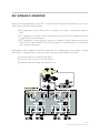
SYSTEM OVERVIEW
The E46 DSC III system consists of the following components:
•
•
•
•
•
•
•
•
•
•
•
•
Control module/Hydraulic Unit (combined)
Four wheel speed sensors
Charge pump
Tandem Brake Master Cylinder
Steering Angle Sensor
Yaw Rate Sensor
Lateral Acceleration Sensor
Two Brake Pressure Sensors
Brake Fluid Level Switch
DSC Button
DSC Warning Indicator
CAN Interface (DME/AGS)
8
E46 Traction and Stability Control Systems
DSC CONTROL OVERVIEW
The Teves DSC system maintains the lateral location forces during all phases of operation
through;
• ABS - Hydraulic intervention preventing the wheels from locking during hard braking
• ASC +T - Engine drive torque reduction and/or hydraulic intervention on the drive
wheels to ensure straight line traction (acceleration - driving and deceleration)
• DSC - Engine drive torque reduction and/or hydraulic intervention on any wheel
brake during cornering to minimize oversteer and understeer conditions
DSC control can aid the driver in controlling the vehicle while driving but can not overcome
the laws of physics if the vehicle is being driven beyond the range of DSC control.
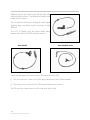
UNDERSTEER/OVERSTEER CONDITIONS
9
E46 Traction and Stability control systems
10
E46 Traction and Stability Control Systems
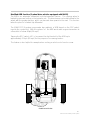
COMPONENTS
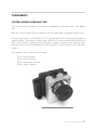
CONTROL MODULE/HYDRAULIC UNIT
The control module is installed in the engine compartment, on the right side, in the battery
well.
Both the control module and the hydraulic unit are replaceable as separate components.
All processing functions for ABS/ASC or DSC regulating functions are carried out in the one
control module. The module is linked to the CAN bus for communication with the DME and
AGS control modules. Additionally the CAN bus is used for communication with the steering angle sensor and for illumination of the ABS and DSC indicator lamps in the instrument
cluster.
The hydraulic unit consists of the following:
•
•
•
•
Four inlet solenoids
Four outlet solenoids
Two changeover solenoids
Two charge solenoids
11
E46 Traction and Stability control systems
WHEEL SPEED SENSORS
The E46 DSC III system uses the same inductive wheel speed sensors from the ASC
system.
BRAKE LIGHT SWITCH
The brake light input signal is used by the control module to interrupt an ASC regulation
control if the driver steps on the brakes during its operation.
This interruption does not take place during DSC regulation.
12
E46 Traction and Stability Control Systems
BRAKE FLUID LEVEL SWITCH
Fluid level switch is incorporated into the brake master cylinder reservoir. If the fluid level is
correct, the switch provides a ground signal to the DCS control module.
If the fluid level drops below the specified level, the switch opens and the ASC/DSC functions are switched off.
DSC BUTTON
The DSC system comes on every time the vehicle is switched on. The DSC button can be
used to switch the system off. The warning indicator lamp comes on when the system is
manually switched off
13
E46 Traction and Stability control systems
STEERING ANGLE SENSOR
The steering angle sensor is mounted at the bottom of the steering column, in front of the
flexible coupling. It utilizes two potentiometers to determine steering angle and the rate of
steering change. These signals are processed in the steering angle sensor and a digital output signal is passed over the CAN bus to the DSC control module.
The sensor requires calibration after repairs to the steering or suspension system. The sensor is calibrated using the DIS or MoDiC. Once calibrated, the sensor sends an ID number
to the DSC control module. The ID provides confirmation to the module that the angle sensor is properly calibrated.
Installing a new sensor or exchanging sensors with another vehicle will require that this calibration procedure is carried out.
14
E46 Traction and Stability Control Systems
CAN INTERFACE
The DSC control module communicates over the CAN line for the following:
•
•
•
•
Steering angle from the steering angle sensor
Engine control module for engine intervention
Transmission control module for shift intervention
Instrument cluster for illumination of the warning indicator lamps
15
E46 Traction and Stability control systems
ROTATION RATE SENSOR
The rotational rate sensor is mounted under the driver's seat. It provides a signal to the DSC
control module that corresponds to the vehicle's rotational speed around its axis (yaw
speed).
The sensor receives its operating power (5 volts) from the DSC control module and provides an output voltage of approx. 0.25 to 4.65 volts depending on the amount of yaw
exerted on the vehicle.
The sensor operates on the Coriolis effect to produce the output voltage. The element of
the sensor is a micromechanical double quartz tuning fork. A frequency of 11 Hertz is
applied to one side of the fork and as the vehicle turns on its axis, vibrations are induced
into the tips at the other end.
The sensor processes the signals produced by the fork and produces an analog voltage
signal that is proportional to the amount of yaw.
Based on the control module's programming parameters, the DSC will activate a DSC regulation cycle to ensure that the vehicle remains stable under all driving conditions.
16
E46 Traction and Stability Control Systems
LATERAL ACCELERATION SENSOR
The lateral acceleration sensor is mounted in the left "A" pillar. The sensor provides the DSC
control module with an input signal that corresponds to the degree of lateral acceleration
("G" forces) acting on the vehicle.
The sensor is a capacitive type with two capacitive plates (one fixed and one moving).
Under the effect of lateral acceleration, the one plate moves in relation to the fixed plate.
This results in a voltage signal being produced in proportion to the degree of lateral acceleration.
The voltage signal output of the sensor to the DSC control module ranges from 0.5 to 4.5
volts. When the vehicle is stationary, The standing voltage from the sensor is approximately 1.8 volts.
This signal is used in conjunction with the yaw sensor input to determine the degree of DSC
regulation required to maintain the vehicle's stability.
17
E46 Traction and Stability control systems
18
E46 Traction and Stability Control Systems
HYDRAULIC SYSTEM COMPONENTS
PRE-CHARGE PUMP
The pre-charge pump is installed between the master cylinder and the brake fluid reservoir.
During DSC controlled regulations that involve brake intervention, the pump ensures that
the required volume of fluid is available for the hydraulic unit.
When activated, the pre-charge pump draws fluid from the reservoir and delivers it to the
master cylinder at a pressure of 10 Bar.
19
E46 Traction and Stability control systems
MASTER CYLINDER/FLUID RESERVOIR
The master cylinder contains the central valves in both the front and rear brake circuits,
Similar to the Bosch DSC system. The central valves allow fluid to transfer during DSC controlled interventions.
The brake fluid reservoir has internal baffles that minimize fluid foaming during controlled
interventions. The charge pump pick up is mounted low on the reservoir to prevent air from
entering the system during regulation. The fluid level switch will signal the control module to
cancel DSC regulation if the fluid is below the safety margin level.
PRESSURE SENSORS
Two pressure sensors are installed on the master cylinder in the outlet ports for the front
and rear brake circuits. The sensors provide the DSC control module with an analog voltage signal in proportion to the brake pressure in the master cylinder.
20
E46 Traction and Stability Control Systems
DSC HYDRAULIC OPERATION
Based on the programming of the DSC control module, hydraulic intervention can be activated at any wheel brake as follows:
• ABS regulation for any wheel that is in danger of locking - causing the wheel to
skid.
• ASC regulation for either or both rear wheels to ensure that the optimum traction
is applied to the drive wheels
• DSC regulation for any wheel to correct for dynamic forces that are causing the
vehicle to become unstable. The DSC intervention only takes place on one wheel
of a corresponding axle.
Depending on the hydraulic intervention required, the charge pump, return pump, change
over valves, charging valves, inlet and outlet solenoids are activated to provide:
• Pressure build up for brake application
• Pressure hold to slow or stop the wheel
• Pressure release to allow the wheel to turn
21
E46 Traction and Stability control systems
DIAGNOSIS
Troubleshooting the E46 TEVES DSC system is carried out using the DIS or MoDiC.
The fault indicators in the instrument panel will illuminate when there is a fault and the system is off line.
Follow the diagnostic procedures as outlined with the tester to troubleshoot the E46 Teves
DSC system.
22
E46 Traction and Stability Control Systems
TEVES DSC III MK60
Model: E46 (except M3 and Xi) and E36/7
Production Date: From 9/00
Objectives
After completing this module you should be able to:
•
Identify the changes of the MK60 over the previous MK20EI system.
•
Understand the operation of the new wheel sensors.
•
Review the operating principles of ABS, ASC and DSC.
•
Describe the new ADB and DBC functions.
23
E46 Traction and Stability Control Systems
Purpose of the system
DSC III MK60 is supplied by Continental Teves and supersedes the Teves DSC III MK20 EI
system. The MK60 includes all of the features of the previous MK20 EI system and incorporates two additional functions:
•
DBC function
•
Modified ADB function
The most important changes from the MK20 EI are:
•
Reduction in size of the control unit/hydraulic Unit.
•
Installation of the hydraulic unit close to the master cylinder.
•
Elimination of a pre-charge pump.
•
Magneto resistive wheel speed sensors.
The Teves MK60 system is designed to maintain the vehicles stability during:
•
ABS braking regulation
•
ASC+T traction control
•
DSC for oversteer and understeer control
Additional features are also programmed into the control module to enhance driver safety
and comfort. These features are:
•
CBC Corner Brake Control
•
EBV
•
MSR
•
ADB
•
DBS Dynamic Brake System
Electronic Brake Proportioning
Engine Drag Torque Regulation
Automatic Differential Brake
24
E46 Traction and Stability Control Systems
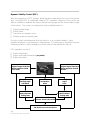
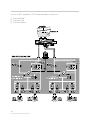
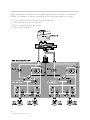
ABS LAMP
KL 30
KL 15
ABS
DME
MAIN
RELAY
POWER SUPPLY
KL 15
POWER SUPPLY
DSC SWITCH
DSC
PUMP
INLET (4X)
LF
WHEEL
OUTLET (4X)
MK60
HYDRAULIC
UNIT
CHANGEOVER (2x)
RF
INTAKE (2x)
SPEED
LR
SENSORS
DSC III
MK 60
RR
BRAKE
PRESSURE
SIGNAL X2
BRAKE
PRESSURE
SENSORS
SIGNAL VOLTAGE
ROTATION
RATE SENSOR
POWER SUPPLY
ROTATION
RATE SENSOR
GROUND
47 PIN
REFERENCE
VOLTAGE
BRAKE
PRESSURE
SENSORS
POWER
GROUND
LATERAL
ACCELERATION SENSOR
STEERING
ANGLE SENSOR
CAN
4
1 2
5
3
4
5
DME
11
0
UNLEADED GASOLINE ONLY
80
80
100
120 140
100
160
180
60
200
40
20
220
240
20
2
120
3
4
5
1/min
x1000
6
1
140
0
km/h
MPH
5030 20 15
12
7
!
BRAKE
BRAKE
ABS
ABS
miles
SERVICE
ENGINE
SOON
+
RIGHT REAR
EML
MK III
!
LEFT REAR
BRAKE
X
PARK BRAKE
SWITCH
PROCESSED WHEEL SPEED
WHEEL SPEED SENSOR REFERENCE VOLTAGE X 4
M
oD
SPLICE TO KOMBI
BMW
DIS
DIAGNOSIS
BMW DIS
BRAKE FLUID
LEVEL SWITCH
DSC LAMP
GENERAL BRAKE
WARNING LAMP
iC
TO LSZ
BMW DIS
BRAKE LIGHT
SWITCH
3
60
40
12
AGS
LATERAL
ACCELERATION SENSOR
1 2
SIGNAL VOLTAGE
25
E46 Traction and Stability Control Systems
System Components
The Teves DSC III MK60 consists of the following components:
•
Integrated Control unit/Hydraulic unit with CAN Interface
•
Tandem Master Brake Cylinder
•
Brake Expansion Tank with Fluid Level Reed Contact in Cap
•
2 Brake Pressure Sensors
•
Brake Light Switch
•
4 Wheel Speed Sensors (active)
•
Rotation Rate Sensor (yaw)
•
Steering Angle Sensor (LEW)
•
Transverse Acceleration Sensor
•
DSC Button (part of SZM)
•
Instrument cluster Warning indicators
•
Hand brake Switch
•
Wiring Harness
26
E46 Traction and Stability Control Systems
Control Unit/Hydraulic Unit
The MK60 control unit/hydraulic unit is located
in the engine compartment on the left side
under the brake master cylinder.
Both the control unit and the hydraulic unit are
replaceable as separate components.
The pre-charge pump used on previous
systems is no longer required. Rapid pressure
build up is possible because of the close
proximity of the hydraulic unit to the master
cylinder and improvements in the design of the
return pump.
The control unit/hydraulic unit itself is 20%
smaller and lighter than the previous MK20 EI.
All processing functions for ABS, ASC or DSC are performed by the combined control
unit/hydraulic unit. The MK 60 control unit is also responsible for processing the wheel
speed signals and providing them to other control units.
The MK60 control unit for MY 2002 incorporates the RDW function into its scope of
control, making a separate RDW control unit unnecessary. The operating principle
continues to be based on the analysis of wheel speed.
27
E46 Traction and Stability Control Systems
MK60 Hydraulic Unit
REAR AXLE BRAKE CIRCUITS
FRONT AXLE BRAKE CIRCUITS
The hydraulic unit consists of an aluminum block containing 12 solenoid valves, 2 pressure
accumulators and the return pump.
•
4 inlet solenoid valves (N/O)
•
2 changeover solenoid valves (N/O)
•
4 outlet solenoid valves (N/C)
•
2 Intake solenoid valves (N/C)
The solenoid valving ensures that normal braking is possible in the event of a defective
control unit.
In ABS regulation the pump returns fluid back to the master cylinder circuits. In ASC/DSC
regulation with brake intervention, the pump is responsible for building up the brake
pressure required for the front and rear hydraulic circuits.
Note:
N/O= Normally Open
N/C= Normally Closed
28
E46 Traction and Stability Control Systems
CAN Interface
The MK60 is connected to the CAN bus for communication with the AGS, DME control
module, Steering Angle Sensor and the Instrument Cluster.
The CAN bus allows all of the connected control modules to send and receive information
and commands.
Communication with the MK60 includes:
•
DME - The DME sends current engine torque. MK60 commands the DME to reduce
(ASC/DSC) or raise (MSR) engine torque.
•
AGS - The MK60 commands the AGS to suppress shifts during regulation.
•
LEW - The MK60 receives steering angle information.
•
KOMBI - The MK60 commands the instrument cluster to activate or deactivate the
warning lamps.
•
All four wheels speed signals are sent over the CAN bus for use by other modules.
INSTRUMENT
CLUSTER
80
GS 20
60
MS 43.0
40
12
0
20
3
100
120 140
100
160
180
60
2
4
5
1/min
x1000
120
6
1
200
40
11
UNLEADED GASOLINE ONLY
80
220
20
240
140
0
km/h
5030 20 15
7
12
MPH
Mmiles
1 2
3
4
5
CAN BUS
SPLICE CONNECTIONS
FOR TWISTED PAIR CAN
LEW
MK 60
29
E46 Traction and Stability Control Systems
Tandem Master Brake Cylinder
The MK60 system uses a tandem master brake
cylinder fitted with central valves as in other DSC
master cylinders. The central valves allow fluid
to be drawn through the master cylinder during
ASC and DSC regulation. The hydraulic circuit is
divided front/rear.
An inlet for pre-charge pressure is no longer
used since the charge pump has been
eliminated from the MK60.
Both brake pressure sensors are mounted on
the master cylinder.
Expansion Tank and Brake Fluid Level Switch
The brake fluid expansion tank
has internal baffles that reduce
foaming during return pump
operation.
The expansion tank includes a
pick-up tube for clutch master
cylinder fluid supply.
The brake fluid level switch is
incorporated into the cap. The
switch is a reed contact switch.
If the brake fluid is at a sufficient
level, the switch is closed and
switched to ground.
If the fluid level drops below a specified level , the reed contacts open and the MK 60
responds by switching off the ASC/DSC functions.
Normal braking and ABS operation is unaffected.
30
E46 Traction and Stability Control Systems
Brake Pressure Sensors
Two brake pressure sensors are mounted on the master cylinder below the outlet ports for
the front and rear brake circuits. The sensors are provided a 5V reference voltage by the
MK 60 control unit.
The sensor provides the control unit with an analog signal proportional to brake pressure.
Voltage increases with increasing brake pressure.
Plausibility with BLS
The signal input from the brake
light switch is compared with the
pressure sensor values.
The pressure sensors must not
detect more that 5 bar when the
BLS is not actuated.
Both signals are used to form a
redundant BLS input which is
constantly monitored.
Note: Refer to the Workshop Hints for instructions on initializing the brake pressure sensors.
Brake Light Switch (BLS)
The brake switch is an input to the MK 60 to inform it that the brakes are being applied. If
the signal is received during an ASC regulation then brake regulation is interrupted.
31
E46 Traction and Stability Control Systems
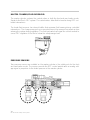
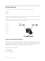
Wheel Speed Sensors (active)
With the introduction of the Teves DSC III MK60, active wheel speed sensors that operate
on the principle of magnetoresistive effect are used for the first time on BMW vehicles.
The sensor element and evaluation module are two separate components within the
sensor housing.
1
6
5
4
8
3
7
10
2
1.
2.
3.
4.
5.
Metal pulse wheel
Magnet
Sensor element
Evaluation module
Support for sensor element
9
6.
7.
8.
9.
10.
Sensor wiring with weather boot
Ground contact ring
Fastening element
Sensor housing
Pick-up surface
Principle of operation of the magnetoresistive sensor
The active sensing of the magnetoresistive sensor is particularly suitable for advanced
stability control applications in which sensing at zero or near zero speed is required.
A permanent magnet in the sensor produces a magnetic field with the magnetic field stream
at a right angle to the sensing element.
The sensor element is a ferromagnetic alloy that changes its resistance based on the
influence of magnetic fields.
32
E46 Traction and Stability Control Systems
As the high portion of the pulse wheel approaches the sensing element, a deflection of the
magnetic field stream is created. This causes the resistance to change in the thin film
ferromagnetic layer of the sensor element.
1
4
5
3
2
1.
2.
3.
4.
5.
Metal pulse wheel
Magnet
Sensor element
Evaluation circuit
Magnetic field
The sensor element is affected by the direction of the magnetic field, not the field strength.
The field strength is not important as long as it is above a certain level. This allows the
sensor to tolerate variations in the field strength caused by age, temperature or
mechanical tolerances.
The resistance change in the sensor element affects the voltage that is supplied by the
evaluation circuit. The small amount of voltage provided to the sensor element is monitored
and the voltage changes (1 to 100mV) are converted into current pulses by the evaluation
module.
•
Signal High-14mA
•
Signal Low-7mA
The sensor evaluation circuit is supplied 12V by the MK60 control unit. Output voltage from
the sensor is approximately 10V. The control unit counts the high and low current pulses
to determine the wheel speed signal.
Front sensors are three wire because they have a separate ground wire.
Rear sensors are two wire and use the sensor case as a ground point.
33
E46 Traction and Stability Control Systems
Different sensors are used on the left and right side
front axle of the vehicle. The difference comes in the
length of the harness.
The connectors are blue to distinguish them apart
from the grey connectors used for sensors on the
MK20 EI.
The DSC III MK60 uses the same metal pulse
wheels used with the MK20 inductive sensors.
Front axle E46/Z3
Rear axle Z3
Rear axle E46, short
There are two types of sensors used in the rear axle of the E46:
•
The short sensor is used on the 325i (any transmission) and 330i automatic.
•
The long sensor is used on the 330i manual transmission version.
The Z3 uses the same sensors for the rear axle, left or right.
34
E46 Traction and Stability Control Systems
Rotation Rate Sensor
The Rotation Rate Sensor is mounted on a metal bracket under the drivers seat. The
sensor provides information to the MK60 concerning the vehicles speed around its main
axis (yaw).
The sensor has a three pin connector with the following connections:
•
•
•
5V reference
Signal
Ground
The sensor receives a reference voltage of 5V from the MK60 control unit and provides a
signal output of approximately 0.25 to 4.65V depending on the amount and direction of
yaw. If the sensor is defective a constant voltage will be sent to the MK60.
The sensor element is a micro-mechanical double quartz tuning fork. A frequency of 11
Hertz is applied to one side of the fork and as the vehicle turns on it’s axis, vibrations are
induced on the other end.
The sensor analyzes the signal produced by the fork and produces an analog voltage
signal that is proportional to the amount of yaw.
The rotation (yaw) rate is compared to the signal from the Steering Angle Sensor and the
Transverse Acceleration Sensor. If physical limits are beginning to be exceeded, the MK60
DSC will begin regulation by engine and brake intervention to attempt to stabilize the
vehicle. This is referred to as a GMR regulation.
Rotation Rate
Sensor
MK60 DSC III
The MK60 DSC III for M.Y. 2002 incorporates a combined Rotation rate and Transverse
Acceleration Sensor. The Sensor is connected to the MK60 control unit by the CAN bus.
The Z3 version will retain separate sensors until the E36/7 is replaced by the E46/6.
35
E46 Traction and Stability Control Systems
Steering Angle Sensor (LEW)
The Steering Angle Sensor is mounted towards the lower end of the steering column,
above the flexible coupling. The LEW consists of a potentiometer and a built in
microprocessor. The potentiometer has two pickups offset at 900 to one another. The raw
potentiometer signal is processed and converted into a digital signal that is transmitted over
the CAN bus to the MK60 DSC III control unit.
Po
te
nt
io
m
et
er
2
Po
te
nt
io
m
et
er
1
High signal
3600
2700
1800
900
00
90
0
1800
2700
3600
The sensor requires initialization in order to create a zero point default. Once initialized the
LEW sends an ID number to the DSC control unit. The ID provides confirmation that the
LEW is properly initialized.
The total steering wheel angle is determined by combining the CAN telegram signal, the
stored zero point default and the actual number of turns to the wheel. In order to prevent
the LEW from loosing count, KL 30 is provided to the sensor and it continues to record
even after the ignition has been switched off.
The MK60 DSC III calculates the drivers desired rate of turn from the steering angle signal.
POTENTIOMETER
HOUSING
Pin 1. KL 30
Pin 2. KL 87
6
PINBUS
CONNECTOR
CAN
CONNECTOR
(5 WIRES)
Pin 3. CAN high
Pin 4. CAN low
Pin 5. KL 31
CAN BUS MICROPROCESSOR
Pin 6. TXD
Note: Refer to the Workshop Hints for instructions on coding and initializing the sensor.
36
E46 Traction and Stability Control Systems
Transverse (Lateral) Acceleration Sensor
The Transverse Acceleration Sensor is
mounted in the left “A” pillar behind the driver’s
foot rest. The sensor provides the MK60 DSC
control unit with a signal that corresponds to
the degree of transverse acceleration (G forces)
acting on the vehicle.
The sensor is a capacitive sensor with two
plates. One plate is rigidly mounted, the other
plate is mounted on a spring. Under the effect
of transverse forces acting on the sensor the
distance between the plates changes.
This change of distance between the plates affects the capacitance of the sensor. The
evaluation circuitry converts the signal into an analog voltage that is transmitted to the
control unit.
The output signal of the sensor is between the range of 0.5 to 4.5 Volts. This corresponds
to -1.5 to 3.5g respectively. When the vehicle is stationary the output is 1.8V.
The transverse acceleration signal is used in the MK60 DSC III control unit along with the
rotation rate and steering angle signal to determine if DSC regulation is required to maintain
the vehicles stability.
Note: Refer to Workshop Hints for instructions on initializing sensor.
37
E46 Traction and Stability Control Systems
DSC Button
The DSC button is located on the SZM, however the SZM provides no processing, it is
simply a housing for the button which is hardwired to the MK60 control unit.
The DSC Button features two functions that can be set by varying the time the button is
held down for:
Button activation Function
Display
Short press
<2.5s
DSC light illuminated
Only the yaw control of the DSC is deactivated.
The ADB and DBC functions remain active.
A higher slip ratio is allowed up to 42 mph for the
purpose of improving traction in slippery
conditions. ASC uses different thresholds.
Long press
>2.5s
All ASC, ADB, DSC, GMR (yaw control) and DBC
control functions are deactivated.
DSC light and general
brake warning light
(yellow ABL) illuminated.
Used for service and use on dynamometers.
Pressing the button again returns the system to normal status. It is not possible to go
directly from one function to the next without first returning to normal status.
DSC
38
E46 Traction and Stability Control Systems
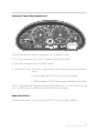
Instrument Cluster Warning Indicators
80
40
12
11
0
20
3
100
60
120 140
100
160
80
180
60
200
40
220
240
20
2
6
1
140
0
5030 20 15
7
12
!
Mmiles
SERVICE
ENGINE
SOON
5
120
km/h
MPH
4
1/min
x1000
BRAKE ABS
EML
Three warning indicator lamps are arranged in the instrument cluster:
•
DSC lamp: Indicates fault in DSC or system disabled by the switch.
•
ABS lamp: Indicates a fault in the ABS system.
•
ABL“BRAKE” lamp: This lamp is a general brake warning and illuminates two different
colors.
• Red indicates low brake fluid or hand brake engaged.
• Yellow indicates DSC/ABS fault or system disabled by the switch.
The DSC and yellow ABL lamp are controlled by the MK60 DSC III control unit via the CAN
bus. The ABS lamp is controlled directly by the MK60 via hardwire.
Hand brake Switch
The hand brake switch is an input to the MK60 DSC to cancel MSR regulation.
39
E46 Traction and Stability Control Systems
Principle of Operation
The scope of control for the MK60 DSC III is comprised of three systems:
•
•
•
ABS
ASC+T
DSC
Based on signals coming from the various sensors, the MK60 DSC III will determine which
system is best suited to maintain control of the vehicle.
In addition to the three basic systems, there are several sub-functions which are activated
during very specific circumstances. The sub-functions are:
•
CBC
•
EBV
CBC
EBV
ABS
ASC
ADB
MSR
• MSR
• ADB
• DBC
•
MBC
MBC
DSC
DBC
System: Anti-Lock Braking System (ABS)
The ABS system can prevent wheel lock when braking by comparing the four active wheel
speed sensors to the average vehicle speed. If a wheel is locking during braking or has
dropped below a speed threshold programmed in the control unit ABS braking will begin.
ABS braking is possible when vehicle speeds are above 12 kph (7mph).
ABS regulation has three phases:
•
•
•
Pressure Build
Pressure Hold
Pressure Release
40
E46 Traction and Stability Control Systems
Pressure Build already occurs during normal braking, so when ABS first intervenes it will
start holding pressure by energizing the Inlet Valve. For example, if the right rear wheel is
locking up, both Inlet Valves will be energized, regulating both wheels together. This logic
is known as Select Low. Front wheels can be regulated individually as needed to prevent
lockup.
Energizing the Inlet Valve closes the brake fluid passage to the calipers and traps the fluid
at the current pressure, thus not allowing the brake pressure to rise any further.
If the wheel speed does not increase the Pressure Release phase begins.
CUITS
FRONT AXLE BRAKE CIRCUITS
Pressure Release occurs when the control unit energizes the Outlet Valve while continuing
to hold the Inlet Valve closed. The trapped brake fluid is released out of the calipers,
reducing braking pressure.
At the same time, the pump is switched on which draws in the released brake fluid and
pumps it back into the pressure-build circuit restoring the volume of brake fluid again in
front of the Inlet valve.
Depending on conditions the ABS system may cycle between these three phases from 3
to 12 times a second to prevent wheel lock.
41
Teves DSC III MK 60
ABS Sub-functions
Corner Brake Control (CBC)
CBC can occur if the vehicle is cornering and ABS regulation is not taking place.
If the control unit detects transverse acceleration in excess of 0.6g and the brakes are
applied, CBC prevents a build up in brake pressure to the inside rear wheel. This prevents
the vehicle from entering into an unstable situation that can lead to Oversteer.
The MK60 accomplishes this by closing the Inlet Valve, thus not allowing brake pressure to
increase at the brake caliper.
The difference in braking force between the two rear wheels creates a yaw force that
opposes the oversteer and allows the vehicle to handle neutrally.
Weight of the
vehicle
Brake pressure
allowed to increase
42
E46 Traction and Stability Control Systems
Brake Pressure
Held
Electronic Brake Force Distribution (EBV)
EBV will adjust brake pressure to the rear axle based on the rate of slow-down of the rear
wheels, ensuring even brake force between the front and the rear of the vehicle.
The control unit monitors the wheel speed when the brakes are applied and compares the
deceleration of the front and rear axle to determine required regulation.
If the vehicle is moderately to fully loaded, the rear axle will take longer to slow down, rear
wheel brakes can then be applied at a higher pressure .
If a vehicle was lightly loaded, a similar brake pressure would be too great and result in an
unstable situation.
If EBV control intervention is required, the control unit cycles the inlet valve on the rear brake
calipers to prevent further build-up.
Benefits of EBV are:
•
•
•
Enhanced braking due to even distribution of brake force.
Rear wheel brake size can be increased.
Front and rear brakes wear at a similar rate.
43
E46 Traction and Stability Control Systems
Automatic Stability Control (ASC+T)
Based on input from the wheel speed sensors, the MK60 control unit determines if the
vehicle is loosing traction due to excessive longitudinal (straight line) wheel slip. An ASC
regulating sequence is initiated if the wheel slip exceeds the control units stored allowable
values.
A critical slip ratio of up to 5% between the wheels will cause the traction control regulation
to begin. This slip ratio is established when the system detects a wheel spin difference of
2MPH or greater.
ASC regulation is cancelled at any time if the brake pedal is applied.
44
E46 Traction and Stability Control Systems
The MK60 can control longitudinal wheel slip by two means:
•
•
Engine Intervention
Brake Intervention (ADB, drive wheels only)
Engine Intervention
Engine torque may be reduced by:
•
•
•
Reducing the throttle opening angle
Retarding the ignition
Canceling individual cylinders by fuel injection cutout.
The MK60 DSC III control unit determines the amount of torque reduction that is
necessary and sends the request for regulation to the DME via the CAN bus.
Brake Intervention (ADB)
Brake intervention is applied to the individual drive wheel which is loosing traction by
regulating the brake calipers in three phases:
•
•
•
Pressure Build
Pressure Hold
Pressure Release
When brake intervention is necessary, the front wheels must be isolated from the Pressure
Build sequence in the hydraulic unit.
Here is an example of an ASC brake intervention at the left rear wheel:
•
The Changeover Valve for the rear brake circuit, the right rear and both front Inlet Valves
are energized and closed.
• The rear brake circuit Intake Valve is energized and opened.
• The Return/Pressure pump is activated and draws brake fluid through the open Intake
Valve from the Master Cylinder (via the Central Valve) and delivers the pressurized fluid to
the open Inlet Valve braking the left rear wheel.
• Pressure Hold and Pressure Release are done by cycling the Inlet and Outlet Valves
similar to the ABS sequence described previously.
The control unit decides which regulation method should take place based on input
criteria and chooses from two regulating principles:
•
•
Select-High
Select-Low
45
E46 Traction and Stability Control Systems
Select-High Regulation
In a Select-High regulation, the MK60 control unit selects the drive wheel with the highest
amount of traction and uses it as the basis for evaluation.
•
•
Engine torque is reduced slightly by request to the DME.
The wheel with the least amount of traction is braked. This allows a torque transfer to
the wheel with the higher amount of traction (similar to a locking differential).
Select-High is used if the vehicle speed is below 40 kph (25 mph).
Select-Low Regulation
In a Select-Low regulation, the MK60 control unit selects the drive wheel with the lowest
amount of traction and uses it as the basis for evaluation.
•
•
Engine torque is reduced until the wheel slip is no longer present.
Brake regulation is not carried out.
Select-Low is used if the vehicle speed is above 40 kph (25 mph).
ASC Sub-functions
Engine Drag Torque Reduction (MSR)
If the vehicle is driven in low gear when coasting down hill, or if there is a sudden shift to a
lower gear, the wheels may be slowed by the engine’s braking effect too rapidly. This could
result in an unstable situation.
If the front wheels are turning faster than the rear wheels, the MK 60 control unit signals the
DME via the CAN bus to raise the engine torque. DME cancels fuel cut-off and allows the
engine speed to increase, this allows the drive wheels to accelerate to match the speed of
the non-driven wheels.
MSR regulation is cancelled if the brake pedal or hand brake are applied.
46
E46 Traction and Stability Control Systems
Modified ADB function (2-wheel drive vehicles equipped with MK60)
The ADB is an automatic differential lock that improves traction. The slipping wheel is
braked by pressure built up in the hydraulic unit. The drive torque can be transferred to the
wheel with the greater traction, which can transmit drive power to the road. This function
takes the place of a limited slip differential.
The MK60 DSC III system incorporates two methods of ADB based on the DSC switch
input to the control unit. With the system “on” the ADB works with engine intervention at
a threshold of below 40kph(24 mph).
Tapping the DSC switch (<2.5 s) increases the slip threshold of the ADB up to
approximately 70 kph (42 mph) for the purpose of increasing traction.
BMW
This feature is also helpful for example when rocking a vehicle out of mud or snow.
BRAKE
APPLIED
Low
High
Coefficient of friction
47
E46 Traction and Stability Control Systems
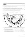
Dynamic Stability Control (DSC)
With the introduction of DSC systems, lateral dynamics were taken into account for the first
time. The MK60 DSC III system will initiate a DSC regulation sequence if the control unit
detects a difference between the drivers desired turning angle and the actual rotation angle
of the vehicle. The control unit determines vehicle stability based on:
•
•
•
•
Steering wheel angle
Wheel speed
Transverse acceleration forces
Rotation angle and speed (yaw)
Once the control unit determines that the vehicle is in an unstable situation, it also
identifies whether it is oversteering or understeering. This distinction is important because
it determines which control strategy should be used to help stabilize the vehicle.
DSC regulation consist of :
•
•
•
Engine intervention
Engine and brake intervention (any wheel)
Brake intervention
Oversteer Detected:
• Engine Torque Reduction.
• Brake applied to outside
wheels.
Understeer Detected:
• Engine Torque Reduction
• Brake applied to inside
rear wheel.
Comparison of
Steering Angle
and Wheel
Lateral
Acceleration
Value
Determination of
Drivers Desired
Turning Rate
Rotation (yaw)
Angle
Value
Determination of
Vehicle Actual
Turning Rate
Establish the Difference
Between Actual and Desired
Determination of Oversteer or Understeer
and Decide on Corrective Action
48
E46 Traction and Stability Control Systems
Understeer
Understeer occurs when the driver wishes to turn a corner but despite the front wheels
being turned in the direction of the curve the vehicle continues its track forward. This
occurs when the front wheels no longer have sufficient lateral locating force (traction).
The MK60 DSC III can identify the situation and initiate a corrective action based on engine
torque reduction followed by a controlled brake intervention sequence if needed.
Engine torque reduction is carried out by the DME from a request by the DSC via the CAN
bus. The DME telegrams the torque reduction confirmation back to the DSC.
Brake intervention is carried out by the MK60 hydraulic unit if the driver is not actively
braking. An example of a brake intervention at the inside rear wheel is as follows:
•
•
•
•
All Inlet Valves are closed except for the right rear inlet.
Intake Valve for rear circuit is opened.
Both Changeover Valves are closed.
Return pump operated.
UNDERSTEER CORRECTION
3. VEHICLE
COMES OUT
OF TURN
SUCCESFULLY
WITH DSC III
3
WITHOUT
DSC III
1. VEHICLE APPROACHES TURN:
- Driver steers into turn
- Brakes are applied
2. DSC III detects an Understeer
Condition based on vehicle speed,
wheel speed differential,
turning angle, lateral acceleration forces
and yaw angle.
- Engine torque reduction active
- Inside rear wheel brake regulate
1
2
- regulated brake slows
wheel down (and helps to
reduce vehicle speed). Wheel on
outside of curve speeds up due to power transfer thru differential.
Vehicle pivots in favor of curve. Combined, this forces the vehicle into the turn.
49
E46 Traction and Stability Control Systems
Just as an ASC regulation, DSC brake intervention carries out:
•
•
•
Pressure Build
Pressure Hold
Pressure release
REAR AXLE BRAKE CIRCUITS
50
E46 Traction and Stability Control Systems
FRONT AXLE BRAKE CIRCUITS
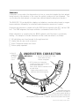
Oversteer
Oversteer occurs when the driver wishes to turn a corner and the tail of the vehicle slides
outward leading the turn. This is caused by the rear tires loosing traction and not being able
to hold against the centrifugal force acting upon the vehicle.
The MK60 DSC III can identify the situation and initiate a corrective action based on engine
torque reduction followed by a controlled brake intervention sequence if needed.
Engine torque reduction is carried out by the DME from a request by the DSC via the CAN
bus. The DME sends the torque reduction confirmation back to the DSC.
OVERSTEER CORRECTION
3. VEHICLE COMES
OUT OF TURN
SUCCESFULLY
1. VEHICLE APPROACES TURN AT HIGH RATE OF SPEED:
- Driver steers into turn and applies brakes to slow down.
WITH DSC III
WITHOUT
DSC III
1
3
2A. Lateral locating forces are
diminished on rear wheels
due to high speed and
centrifugal force of
vehicle in turn.
2
2D. The torque reduction and rear brake regulation
should stabilize the vehicle at this point. If not
the left front wheel has a high degree of lateral
locating force and is momentarily regulated.
This action deliberately causes the wheel to shed
a calculated degree of it's locating force. This
counteracts oversteer yaw at this wheel and also
aids in slowing the vehicle down to correct it.
2B. Driver tries to compensate by oversteering which
diminishes lateral locating force even further.
Simultaneously, rear of car starts to slide out.
2C. DSC III determines an OVERSTEER condition.
Engine torque is reduced via CAN Bus signalling.
Outside rear wheel is momentarily regulated to
counteract severe yaw angle (also helps to reduce
drive torque further.)
51
E46 Traction and Stability Control Systems
Brake intervention is carried out by the MK60 hydraulic unit if the driver is not actively
braking. An example of a brake intervention at the left outside wheel is as follows:
•
•
•
•
All Inlet Valves are closed except for the left rear inlet.
Intake Valve for rear circuit is opened.
Both Changeover Valves are closed.
Return pump operated.
REAR AXLE BRAKE CIRCUITS
52
E46 Traction and Stability Control Systems
FRONT AXLE BRAKE CIRCUITS
DSC Sub-functions
Dynamic Brake System (DBS)
DBS is designed to assist the driver in emergency braking situations by automatically
increasing pressure to the vehicles brake system. This allows the vehicle to stop in the
shortest distance possible. DBS was first available in 1999 Bosch DSC III 5.7 systems. It
is available on a Continental Teves system for the first time with MK60 DSC III.
The DBS system contains two functions: Dynamic Brake Control and Maximum Brake
Control. DBS functions are programmed into the MK60 control unit and require no additional hardware over conventional DSC.
Dynamic Brake Control (DBC)
The DBC function is designed to provide an increase in braking pressure up to the ABS
threshold during rapid (emergency) braking situations. The MK60 control unit monitors the
inputs from the brake light switch and the brake pressure sensors on the master cylinder.
The triggering criteria for activation of DBC is, how rapidly is the brake pressure increasing
with an application of the brake pedal. The triggering conditions are:
•
•
•
•
•
•
•
Brake light switch on.
Brake pressure in the master cylinder above threshold.
Brake pressure build-up speed above threshold.
Vehicle road speed above 3mph (5kmh).
Pressure sensor self test completed and sensors not faulted.
Vehicle traveling forward.
Not all of the wheels in ABS regulation range.
If the threshold for DBC triggering is achieved, the MK60 control unit will activate a
pressure build-up intervention by activating the return pump. The pressure at all wheels is
increased up to the ABS regulation point. This ensures that the maximum brake force is
applied to the vehicle.
During DBC the rear axle is controlled with Select-Low logic and the front wheels are
regulated individually. DBC will continue until:
•
•
•
The driver releases the brake pedal.
Brake pressure falls below threshold.
Vehicle road speed below 3mph.
DBC will also be switched off if a fault occurs in with any of the necessary input sensors.
A fault in DBC will illuminate the “BRAKE” (ABL) lamp yellow to warn the driver, depending
on the type of failure the DSC lamp may be illuminated as well.
53
E46 Traction and Stability Control Systems
Maximum Brake Control (MBC)
The MBC function is designed to support driver initiated braking by building up pressure in
the rear brake circuit when the front wheels are already in ABS regulation.
The additional braking pressure is applied to bring the rear wheels up to the ABS
regulation point shortening the stopping distance. The MBC function is triggered when the
brakes are applied more slowly than the threshold needed for a DBC regulation. The triggering conditions are:
•
•
•
•
•
Both front wheels in ABS regulation.
Vehicle road speed above 3mph (5kmh).
DBC and pressure sensor initialization test successful.
Vehicle traveling forward.
Rear wheels not in ABS regulation.
If the threshold for MBC triggering is achieved, the MK60 control unit will activate a
pressure build-up intervention by activating the return pump. The pressure at the rear
wheels is increased up to the ABS regulation point. This ensures that the maximum brake
force is applied to the vehicle.
The MBC function will be switched off if:
•
•
•
•
Front wheels drop out of ABS regulation.
The driver releases the brake pedal.
Brake pressure falls below threshold.
Vehicle road speed below 3mph.
MBC will also be switched off if a fault occurs in with any of the necessary input sensors.
A fault in MBC will illuminate the “BRAKE” (ABL) lamp yellow to warn the driver, depending
on the type of failure the DSC lamp may be illuminated as well.
54
E46 Traction and Stability Control Systems
Workshop Hints
Diagnosis
Diagnosis of the MK60 DSC III is carried out using the DISplus or MoDiC
Control Unit Functions:
Expert mode diagnosis available
at any time during troubleshooting. To enter: press the Control
Unit Functions button at the
right lower corner of the screen.
The contents are:
• Identification
• Delete Fault Memory
• Read Fault Memory
• Component Activation
• Status queries (requests)
Service Functions:
Provides access to specialized test modules
used as post repair procedures. To enter:
• Function Selection
• Service Functions
• Chassis
• Dynamic Stability Control MK60
The contents are:
• Connection Speed Sensor: A test to
verify the proper wiring to the wheel
speed sensors
• Connection Brake Lines: A test to
verify the proper brake pipe connections
to the hydraulic unit.
• Adjustment Functions: Test modules
to initialize certain components after
repair work is performed
• Steering Angle Sensor
• Lateral Acceleration Sensor
• Pressure Sensors
Test Modules: Faults with the MK60 system can be diagnosed using fault or symptom driven test
modules. To begin diagnosis:
• Perform the Quick Test.
• Select Vehicle Symptom from the Symptom Selection page.
• Select Test Module from Test Plan page.
• Press the Test Schedule Button.
Test Modules are configured in the E46 diagnosis concept.
55
E46 Traction and Stability Control Systems
Coding
Coding must be performed after replacement
of the MK60 control module or the steering
angle sensor. ZCS coding is found in the
Coding and Programming selection from the
start screen or when pressing the Change
button. Follow on-screen instructions for
initialization of components after completing
the coding process.
Print
Change
End
Services
BMW Coding/programming SELECTION
1
2
3
4
5
6
CAR MEMORY
KEY MEMORY
ZCS CODING
PROGRAMMING
ALIGNMENT EWS-DME
ALIGNMENT EWS-DDE
Note
Adjustment Functions
Adjustment (initialization) is required when:
• Replacing the MK60 Control Unit.
• Replacing/Re-coding the Steering Angle Sensor.
• Replacing one or both Brake Pressure Sensors.
• Replacing Lateral Acceleration Sensor.
Steering Angle Sensor
The steering angle sensor requires an offset adjustment after the sensor has been replaced,
coded or after repairs to the steering or suspension system. The offset adjustment informs
the steering angle sensor processor of the straight ahead position of the front wheels.
The adjustment is performed by completing the Test Module found in Service Functions.
Once the adjustment is complete the sensor sends an identification number over the CAN
bus to the DSC control unit. The ID provides confirmation that the steering angle sensor is
coded and has successfully completed the adjustment procedure.
Special Tools
Special Tools available for the Teves DSC III MK60 consist of:
47 Pin V-Cable 34 5 250
56
E46 Traction and Stability Control Systems
60 Pin Break-Out-Box