1
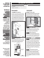
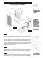
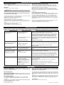
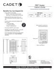
The RBF Series
OWNER’S GUIDE
Features & Benefits
■ Primary and Secondary Thermal
Safeguards
• Commercial grade high temperature
manual reset
• Over-temperature one-time thermal
device
■ Nichrome element wrapped around
mica insulators for durability
■ Powder coat paint process eliminates
sharp cutting edges
■ Stainless steel grill and frame
■ Convenient ON-OFF rocker switch
control
■ Two year extended warranty
■ Wall can designed for bottom wiring
and ease of installation
■ Factory tested and UL listed
■ Retrofits into model RBC wall can
Tools Required:
Phillips Screwdriver
Straight Screwdriver
Wire Strippers
MODELS:
RBF101
Utility Knife
4 11⁄2" Wood Screws
3 Insulated Wire Connectors
1 Strain Relief Connector
(Supersedes RB Models; RB101 & RB121)
IMPORTANT INFORMATION
WARNING
Turn the electrical power off at the electrical
panel board (circuit breaker or fuse box) and lock
or tag the panel board door to prevent someone
from turning on power while you are working on
the heater. Failure to do so could result in serious
electrical shock, burns, or possible death.
6.
WARNING
DO NOT install the heater in a floor, ceiling, or behind
doors. Overheating or fire may occur.
7.
WARNING
DO NOT install heater in any area where combustible
vapors, gases, liquids, or excessive lint or dust are present. Fire or explosion may occur.
8.
WARNING
Risk of Electrical Shock. Connect grounding lead to
grounding wire provided. Keep all foreign objects out of
heater.
9.
WARNING
Risk of Fire. Heater must be kept clear of all obstructions: a
minimum of 3’ in front, 6” above and on both sides.
Heaters must be kept clean of lint, dirt and debris. (See
Maintenance Instructions)
1. Read all instructions and information labels. Verify the
electrical supply wires are the same voltage as the
heater.
2. All electrical work and materials must comply with the
National Electric Code (NEC), the Occupational Safety and
Health Act (OSHA), and all state and local codes.
3. The heater must be grounded to the grounding pigtail
(copper wire) provided in the wall can.
4. If you need to install a new circuit or need additional
wiring information, consult a qualified electrician.
5. Protect electrical supply from kinks, sharp objects, oil,
grease, hot surfaces or chemicals.
SAVE THESE INSTRUCTIONS
TEL: 360-693-2505 Fax: 360-694-6939 P.O. Box 1675 Vancouver, WA 98668-1675
READ ALL
INSTRUCTIONS
AND SAFETY
INFORMATION
Installation Instructions
Part One
PLACEMENT: UL approved for vertical installation only.
CONTROL OF HEATER: ON-OFF control built into product.
IMPORTANT!
It is extremely
important you
verify the
electrical supply
wires are the
same voltage as
the heater (i.e. 120
volt heater to 120
volt power supply
and 240 volt heater
to 240 volt power
supply). If
replacing an
existing heater,
check the labels
of the old heater
and replace using
the same voltage.
Hooking a 240 volt
heater to a 120 volt
power supply will
drastically reduce
the heater's
output. Hooking a
120 volt heater to a
240 volt power
supply will
destroy the heater.
Connecting your
heater to an
incompatible
power supply will
void the warranty.
How do I install for
new construction?
How do I install in
an existing wall?
STEP 1 Mount The Wall Can
STEP 1 Cut Hole In Wall
The wall can is designed to fit between two standard 16" on-center studs. UL requires a minimum
clearance of 6" adjacent vertical surfaces such
as walls, shelving, drapes, etc. Manufacturer recommends 12" from finished floor and adjacent
surfaces. (Note: Front edge of wall can must be
flush with finished wall. If installing on unfinished
wall; face of wall can must extend from face of
stud to allow for thickness of sheetrock.) Secure
the wall can to the studs with two screws or
nails, right or left hand mounting (See Figure 1).
Cut a hole 10 1/4" wide by 16 3/4" high next to wall
stud. UL requires a minimum clearance of 6" adjacent vertical surfaces, such as walls, shelving,
drapes, etc. Manufacturer recommends 12" from
finished floor and adjacent surfaces (See Figure 2).
Wall Can
FIGURE 2
Screw
STEP 2 Route Supply Wires
Ground Wire
Ground Screw
STEP 3 Mount The Wall Can
Supply Wires
FIGURE 1
Screw
STEP 2 Route Supply Wires
Route supply wire from circuit breaker through
opening in bottom of wall can and secure with
strain relief connector, leaving 6" to 10" wire lead
for later use. Connect supply ground wire to
grounding pigtail in wall can (See Figure 1).
NON-RESETABLE
HIGH TEMPERATURE LIMIT
HEATING ELEMENT
MANUAL RESET
HIGH TEMPERATURE
LIMIT
BLACK
MOTOR
WHITE
Warranty is void if
any material is
sprayed on the
element or blower.
Use paintmask
provided if walls
are to be textured
or painted.
Route supply wire from circuit breaker through
opening in bottom of wall can and secure with
strain relief connector, leaving 6" to 10" wire lead
for later use. Connect supply ground wire to
grounding pigtail in wall can (See Figure 1).
WHITE
N
L1
BLACK
DOUBLE POLE
SINGLE THROW
SWITCH
RBF
Wiring Diagram
The wall can is designed to fit between two standard 16" on-center studs. Note: Front edge of wall
can must be flush with finished wall (See Figure 2).
Secure the wall can to the studs with two screws
or nails, right or left hand mounting (see Figure 1).
Part Two
STEP 1 Insert Heater Assembly Into Wall Can
Install heater assembly: Install spring clips on wall
can edge, two at the top and two at the bottom
(See Figure 3). Lay heater assembly on its front
surface, position so rocker switch will be installed
at bottom of wall can (See Figure 4). Make the connection of the supply wires to the lead wires from
the rocker switch. Position the heater assembly to
fit adapter plate to the surface of the wall can (See
Figure 3). Be sure all lead wires are inside the wall
can before securing heater assembly. (Use the
four #10 32 x 1/2" machine screws; two at top and
two at bottom).
STEP 2 Install Grill Frame and Grill
Remove protective film from grill before installing
grill. Place grill frame outside top and bottom
flanges of the heater assembly. Place grill over
frame and secure with the four finishing washers
and four #10 x 11/2" Phillips oval head sheet metal
screw. (See Figure 3). Start all four screws before
tightening (Note: Over tightening screws may damage grill).
Installation Instructions
Installing RBF As Replacement For RB Heater
WARNING
Risk of Electrical
Shock. Connect
grounding lead to
grounding wire
provided. Keep all
foreign objects out
of heater.
Spring Clip
Wall Can
Heater Assy.
Spacer Frame
Grill
Lead Wires
Ground Wire
Heater Assy. Screw
Supply Wires
FIGURE 3
Washer
Rocker Switch
Grill Screw
WARNING
Risk of Fire.
Heater must be
kept clear of all
obstructions: a
minimum of 3’ in
front; 6’’ on both
sides and above.
Heaters must be
kept clean of lint,
dirt and debris.
FIGURE 4
STEP 1 Removing RB heater:
A. Turn off power to the heater being replaced. Turn the thermostat to the highest setting and wait approximately 30 seconds (120 seconds for some electronic thermostats). If the heater turns on, you have turned off
the wrong circuit breaker at the electrical panel board. If heater does not turn on, proceed to next step.
B. Remove knob (if applicable) and screws to remove grill.
C. Remove heatbox from wall can, using the front of the heater to pull it free of the wall can. Be careful to
not touch the heating element or any of the electrical terminals on the back of the heatbox or fan motor.
D. (At this point you can make certain that power is turned off to the heater by using either a voltmeter or
circuit tester. Test each terminal of the Secondary Over-Temperature control to ground. No voltage should
be present! If no voltage is present, continue with the next step. If voltage is present, the right breaker or
fuse for this heater has not been found. Locate correct breaker or fuse before continuing.) Separate the
connection of the supply wires and lead wires.
STEP 2 Install heater assembly:
Install spring clips on wall can edge, two at the top and two at the bottom (See Figure 3). Lay heater assembly on its front surface, position rocker switch to be installed at bottom of wall can (See Figure 4). Make the
connection of the supply wires to the lead wires from the rocker switch. Position the heater assembly to fit
adapter plate to the surface of the wall can (See Figure 3). Be sure all lead wires are inside the wall can
before securing heater assembly (Use the four #1 32 x 1⁄2" machine screws; two at top and two at bottom).
STEP 3 Install Grill Frame and Grill:
Remove protective film from grill before installing grill. Place grill frame outside top and bottom flanges of
the heater assembly. Place grill over frame and secure with the four finishing washers and four #10 x 11/2"
Phillips oval head sheet metal screws (See Figure 3). Start all four screws before tightening (Note: Over
tightening screws may damage grill).
WARNING
Turn the electrical
power off at the
electrical panel
board (circuit
breaker or fuse
box) and lock or
tag the panel board
door to prevent
someone from
turning on power
while you are
working on the
heater. Failure to
do so could result
in serious electrical shock, burns,
or possible death.
Operation & Maintenance
How to operate your heater
1. Once installation is complete and power has been restored, turn the heater
switch on. Important: The heater will remain on until it is manually turned off.
Maintenance
As needed, or every six months, minimum.
1.)
WARNING! Before removing grill, turn the electrical power off at the
electrical panel board (circuit breaker or fuse box). Lock or tag the panel
board door to prevent someone from accidentally turning the power on while
you are working on the heater. Failure to do so could result in serious electrical shock, burns, or possible death.
2.) Turn the heater switch to on. If the heater turns on, you have turned off the
wrong circuit breaker at the electrical panel board.
3.) If heater does not turn on, proceed with next step.
4.) Remove screws and take off grill.
5.) Wash grill with hot soapy water and dry immediately.
6.) While holding fan (to avoid damage or bending), use a hair dryer or vacuum on blow cycle to blow debris through the top element (Do not touch element).
7.) Vacuum fan area without touching the elements.
8.) Replace grill and secure with screws.
9.) Turn power back on at the electrical panel board.
About the Heater Temperature-Limiting Controls
The heater is protected by two temperature-limiting controls . The first is a
high temperature reset switch, designed to open the heater circuit when
excessive operating temperature is detected. The problem must be assessed
and the limit must be reset to resume operation.
Further protection is provided by a secondary over-temperature switch,
which will open the heater circuit in severe over-temperature conditions, or
in the event of component failure. If this occurs, the heater must be repaired
or replaced.
Resetting the Manual-Reset Limit Control
If the manual-reset limit control has opened the heater circuit due to excessive operating temperatures, the heater will not work until the limit reset button is pressed. After allowing the unit to cool for at least 10 minutes and
resolving the problem causing the limit to trip; use a narrow object such as a
ball-point pen to access the reset button through the center section of the
heater grill. Press FIRMLY and be sure to listen and feel for a click, indicating
it has been reset.
Note that resetting the manual limit control may not restore heater operation
if a severe over-temperature condition has occurred. See the
Troubleshooting Chart below for more information.
Troubleshooting Chart
CONSULT LOCAL ELECTRICAL CODES TO DETERMINE WHAT WORK MUST BE PERFORMED BY QUALIFIED ELECTRICAL SERVICE PERSONNEL.
Symptom
Problem
Solution
Breaker trips immediately upon
energizing heater.
1.Incorrect supply voltage.
2.Overloaded circuit.
Heater fan operates, but does
not discharge warm air.
1.Insufficient element temperature.
2.Incorrect supply voltage.
3.Element has failed.
1. Allow a few moments for element to reach operating temperature.
Heater discharges smoke or
emits a burnt odor.
1.Dust, lint or other matter has
accumulated inside heater.
1. Clean heater (see "Operation & Maintenance" section for instructions).
Element heats for a moment
without the fan turning, then
immediately stops heating.
1.Defective motor or internal con- 1. Heater or fan motor requires replacement.
nection.
2.Fan or motor jammed.
2. Remove obstruction and press heater reset button (after allowing
the unit to cool). Test heater operation--if reset button has been
pressed (be sure to listen and feel for a click indicating it has been
reset), but heater does not run, heater requires replacement.
Heater does not run.
1.Heater has tripped the high-temperature reset switch.
2.Heater has tripped the secondary over-temperature switch.
3.Power not on at the circuit
breaker.
4.Broken or poorly connected
wire(s) to heater.
1. Verify that supply voltage matches the heater rating.
2. The total amperage of all heaters on a branch circuit must not be
more than 80% of the amperage rating of the circuit breaker and
supply wire ratings. Reduce the number of heaters on the circuit.
3. Shorted supply or heater wires may be accompanied by severe
3.A short circuit exists in the supsparking. Inspect all supply and heater wiring insulation for damply or heater wiring.
age. Do not reset the circuit breaker until all electrical shorts have
been repaired.
4.Defective circuit breaker.
4. Replace the circuit breaker.
2. Verify that supply voltage matches the heater rating.
3. Replace element.
1. Press the heater reset button (see "Operation & Maintenance" section for instructions).
2. A severe over-temperature condition has occurred. Repair or
replace heater.
3. Turn on the correct circuit breaker in the main panel.
4. Turn off power at circuit breaker. Check supply wire continuity and
proper connection to heater wires.
Warranty
LIMITED ONE-YEAR WARRANTY: Cadet Manufacturing Co. will repair or replace any
Cadet product, including thermostats, found to be defective or malfunctioning from first
date of purchase through the first year.
CADET SHALL NOT BE LIABLE FOR DAMAGES SUCH AS PROPERTY DAMAGE
AND/OR INCIDENTAL EXPENSES RESULTING FROM BREACH OF THESE WRITTEN
WARRANTIES OR ANY IMPLIED WARRANTY.
Extended Product Warranty
These warranties give you specific legal rights, and you may also have other rights which
vary from state to state. Cadet neither assumes, nor authorizes anyone to assume for it,
any other obligation or liability in connection with these electric heaters or any part of such
heaters.
LIMITED TWO-YEAR WARRANTY: Cadet Manufacturing Co. will repair or replace any
RBF series element or motor found to be defective or malfunctioning from first date of purchase through the second year.
These warranties do not apply:
1. To conditions resulting from improper installation or incorrect supply voltage;
2. To conditions resulting from improper maintenance, misuse, abuse, accident, or
alteration;
3. To service calls, or any warranty labor not performed at the Cadet Manufacturing facility;
4. If the date of manufacture cannot be determined;
5. To freight damaged products.
©2004 Cadet Manufacturing Co.
If the product should become defective during the warranty period, contact Cadet
Manufacturing Co. at 360-693-2505 for instructions on how to have the repair or
replacement processed. Products returned without authorization will be refused.
Parts and Service
Contact Cadet for information on Parts or Service.
Printed in U.S.A. 01/07 #720196