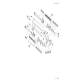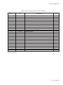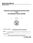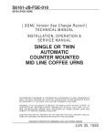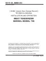
1
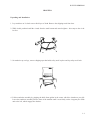
S6151-DL-MMM-010
0910-LP-019-0600
[ SGML Version See Change Record ]
TECHNICAL MANUAL
INSTALLATION AND OPERATION
MEAT TENDERIZER
BERKEL MODEL 705
DISTRIBUTION STATEMENT E: DISTRIBUTION AUTHORIZED TO DOD COMPONENTS
ONLY; CRITICAL TECHNOLOGY; DATE OF PUBLICATION. OTHER REQUESTS SHALL
BE REFERRED TO THE NAVAL SEA SYSTEMS COMMAND (SEA-09B2).
WARNING: THIS DOCUMENT CONTAINS TECHNICAL DATA WHOSE EXPORT IS
RESTRICTED BY THE ARMS EXPORT CONTROL ACT (TITLE 22. U.S.C. SEC. 2751 ET.
SEQ.) OR EXECUTIVE ORDER 12470. VIOLATIONS OF THESE EXPORT LAWS ARE
SUBJECT TO SEVERE CRIMINAL PENALTIES.
DESTRUCTION NOTICE: DESTROY BY ANY METHOD THAT WILL PREVENT DISCLOSURE OF CONTENTS OR RECONSTRUCTION OF THE DOCUMENT.
PUBLISHED BY DIRECTION OF COMMANDER, NAVAL SEA SYSTEMS COMMAND
21 FEB 1979
TITLE-1 / (TITLE-2 Blank)@@FIpgtype@@TITLE@@!FIpgtype@@
@@FIpgtype@@TITLE@@!FIpgtype@@
TITLE-2
@@FIpgtype@@BLANK@@!FIpgtype@@
S6151-DL-MMM-010
RECORD OF CHANGES
CHANGE NO.
DATE
TITLE OR BRIEF DESCRIPTION
ENTERED BY
NOTE
THIS TECHNICAL MANUAL (TM) HAS BEEN DEVELOPED FROM AN INTELLIGENT ELECTRONIC
SOURCE KNOWN AS STANDARD GENERALIZED MARKUP LANGUAGE (SGML). THERE IS NO
LOEP. ALL CHANGES, IF APPLICABLE, ARE INCLUDED. THE PAGINATION IN THIS TM WILL NOT
MATCH THE PAGINATION OF THE ORIGINAL PAPER TM; HOWEVER, THE CONTENT IS
EXACTLY THE SAME. ANY CHANGES RECEIVED AFTER RECEIPT OF THIS TM WILL ONLY FIT
IN THIS PAGINATED VERSION.
RECORD OF CHANGES-1 / (RECORD OF CHANGES-2 Blank)
RECORD OF CHANGES-2
@@FIpgtype@@BLANK@@!FIpgtype@@
S6151-DL-MMM-010
FOREWORD
Ships, training activities, supply points, depots, Naval Shipyards and Supervisors of Shipbuilding are
requested to arrange for the maximum practical use and evaluation of NAVSEA technical manuals. All errors,
omissions, discrepancies, and suggestions for improvement to NAVSEA technical manuals shall be reported to
the Commander, NAVSURFWARCENDIV, 4363 Missile Way, Port Hueneme, CA 93043–4307 on NAVSEA/
SPAWAR Technical Manual Deficiency/Evaluation report (TMDER), NAVSEA Form 4160/1. To facilitate such
reporting, one copy of NAVSEA Form 4160/1 is included at the end of each bound part of each technical manual.
All feedback comments shall be thoroughly investigated and originators will be advised of action resulting therefrom. Extra copies of NAVSEA Form 4160/1 may be requisitioned from DDSP Susquehanna Pennsylvania, 05 E
Street, Mechanicsburg, PA 17055–5003. (S/N 0116–LP-019–5300).
FOREWORD-1 / (FOREWORD-2 Blank)
FOREWORD-2
@@FIpgtype@@BLANK@@!FIpgtype@@
S6151-DL-MMM-010
TABLE OF CONTENTS
Chapter/Paragraph
Page
Unpacking and Installation
. . . . . . . . . . . . . . . . . . . . . . . . . . . . . . . .
1-1
CLEANING AND MAINTENANCE . . . . . . . . . . . . . . . . . . . . . . . . . . .
1-3
REASSEMBLY . . . . . . . . . . . . . . . . . . . . . . . . . . . . . . . . . . . . . . .
1-5
BERKEL MODEL 705 - SPECIFICATIONS
CONSTRUCTION: . . . . . . . . . .
TENDERIZING GROUP: . . . . . .
SAFETY FEATURES: . . . . . . . .
PRODUCT CAPACITY: . . . . . . .
DIMENSIONS: . . . . . . . . . . . .
MOTOR: . . . . . . . . . . . . . . . .
TRANSMISSION: . . . . . . . . . .
OUTPUT SPEED: . . . . . . . . . . .
NET WEIGHT: . . . . . . . . . . . .
SHIPPING WEIGHT: . . . . . . . . .
.
.
.
.
.
.
.
.
.
.
.
1-6
1-6
1-6
1-6
1-6
1-6
1-6
1-6
1-6
1-6
1-6
. . . . . . . . . . . . . . . . . . . . . . . . . . . . . . . . . . . . .
1-7
OVERLOADING
.
.
.
.
.
.
.
.
.
.
.
.
.
.
.
.
.
.
.
.
.
.
.
.
.
.
.
.
.
.
.
.
.
.
.
.
.
.
.
.
.
.
.
.
.
.
.
.
.
.
.
.
.
.
.
.
.
.
.
.
.
.
.
.
.
.
.
.
.
.
.
.
.
.
.
.
.
.
.
.
.
.
.
.
.
.
.
.
.
.
.
.
.
.
.
.
.
.
.
.
.
.
.
.
.
.
.
.
.
.
.
.
.
.
.
.
.
.
.
.
.
.
.
.
.
.
.
.
.
.
.
.
.
.
.
.
.
.
.
.
.
.
.
.
.
.
.
.
.
.
.
.
.
.
.
.
.
.
.
.
.
.
.
.
.
.
.
.
.
.
.
.
.
.
.
.
.
.
.
.
.
.
.
.
.
.
.
.
.
.
.
.
.
.
.
.
.
.
.
.
.
.
.
.
.
.
.
.
.
.
.
.
.
.
.
.
.
.
.
.
.
.
.
.
.
.
.
.
.
.
.
TENDERIZER GROUP . . . . . . . . . . . . . . . . . . . . . . . . . . . .
A. TENDERIZER BLADE ASSEMBLY REPAIR . . . . . . . . . . .
B. BLADE SHAFT ASSEMBLY REPLACEMENT (4575-0059 front,
4575-0061 rear) . . . . . . . . . . . . . . . . . . . . . . . . . .
C. BLADE FRAME ASSEMBLY . . . . . . . . . . . . . . . . . . . .
D. STRIPPER PLATE . . . . . . . . . . . . . . . . . . . . . . . . . .
A. MAGNET . . . . . . . . . . . . . . . . . . . . . . . . . . . . . . .
B. PIN ASSEMBLY . . . . . . . . . . . . . . . . . . . . . . . . . . .
.
.
.
.
.
.
.
.
.
.
.
.
.
.
.
.
.
.
.
.
.
.
.
.
.
.
.
.
.
.
1-9
1-9
1-10
1-10
1-11
ELECTRICAL COMPONENTS . . . . . . . . . . . . .
A. TROUBLE SHOOTING . . . . . . . . . . . . .
B. MOTOR REPLACEMENT . . . . . . . . . . . .
C. ON-OFF POWER SWITCH (2675-0015) . . . .
D. MICRO-SWITCH ADJUSTMENT (4175-0020)
.
.
.
.
.
.
.
.
.
.
.
.
.
.
.
.
.
.
.
.
.
.
.
.
.
.
.
.
.
.
1-11
1-11
1-15
1-17
1-18
FLEXIBLE COUPLING REPLACEMENT (2375-0095) . . . . . . . . . . . . . . . .
1-19
GEAR BOX REPAIR . . . . . .
TOOLS & MATERIALS
A. Gear Box Disassembly .
B. GEAR REPLACEMENT
C. Gear Box Reassembly .
1-19
1-19
1-20
1-24
1-26
.
.
.
.
.
.
.
.
.
.
.
.
.
.
.
.
.
.
.
.
.
.
.
.
.
.
.
.
.
.
.
.
.
.
.
.
.
.
.
.
.
.
.
.
.
.
.
.
.
.
.
.
.
.
.
.
.
.
.
.
.
.
.
.
.
.
.
.
.
.
.
.
.
.
.
.
.
.
.
.
.
.
.
.
.
.
.
.
.
.
.
.
.
.
.
.
.
.
.
.
.
.
.
.
.
.
.
.
.
.
.
.
.
.
.
.
.
.
.
.
.
.
.
.
.
.
.
.
.
.
.
.
.
.
.
.
.
.
.
.
.
.
.
.
.
.
.
.
.
.
.
.
.
.
.
.
.
.
.
.
.
.
.
.
.
. . . . . .
. . . . . .
.
.
.
.
.
.
.
.
.
.
.
.
.
.
.
.
.
.
.
.
.
.
.
.
.
.
.
.
.
.
1-7
1-7
i
S6151-DL-MMM-010
LIST OF TABLES
Table
ii
Title
Page
PARTS LIST FOR FRAME, MOTOR AND GEAR BOX . . . . . . . . . . . . . . .
1-34
PARTS LIST FOR BLADE AND BLADE FRAME
1-39
. . . . . . . . . . . . . . . . . .
S6151-DL-MMM-010
LIST OF ILLUSTRATIONS
Figure
Title
Page
Model 705 Tenderizer . . . . . . . . . . . . . . . . . . . . . . . . . . . . . . . . . . .
0-0
Gear Box . . . . . . . . . . . . . . . . . . . . . . . . . . . . . . . . . . . . . . . . . .
1-27
Frame, Motor, and Gearbox . . . . . . . . . . . . . . . . . . . . . . . . . . . . . . . .
1-31
Model 705 Tenderizer Blade Assembly Options . . . . . . . . . . . . . . . . . . . . .
1-33
Specifications . . . . . . . . . . . . . . . . . . . . . . . . . . . . . . . . . . . . . . . .
1-34
iii / (iv Blank)
iv
@@FIpgtype@@BLANK@@!FIpgtype@@
S6151-DL-MMM-010
SECTION
SERVICE MANUAL
1 / ( Blank)
2
@@FIpgtype@@BLANK@@!FIpgtype@@
S6151-DL-MMM-010
CHAPTER 1
Unpacking and Installation
1. Lay tenderizer on it’s back onto a thick layer of cloth. Remove the shipping studs from base.
2. While in this position install the 4 studs from the small carton and wrench tighten . Also snap on the 4 rubber feet.
3. Set tenderizer up on legs, remove shipping tape that holds safety neck in place and tip safety neck back.
4. Lift the tenderizer assembly by gripping the knife frame guides in the center, with drive clutches to your left.
Lower the tenderizer assembly into the front of the machine until it rests firmly on the 4 support pins. Slide
unit to the left, which engages the clutches.
1-1
S6151-DL-MMM-010
5. Lower the safety neck forward into the operating position.
NOTE
THIS TENDERIZER WILL NOT OPERATE WITHOUT THE SAFETY NECK
IN PLACE. NEVER RAISE OR LOWER THE SAFETY NECK WITH THE
MACHINE TURNED ON, BOTH FOR PERSONAL PROTECTION AND
MACHINE PROTECTION. ALWAYS TURN MACHINE OFF WHEN NOT IN
USE. ONLY RUN MACHINE BY USING THE ON-OFF SWITCH - NEVER
BY RAISING THE NECK.
6. Uncoil power cord and plug it into the specified electrical receptacle. (Specifications for this machine are
found on the plate located on the left hand leg.)
7. Turn OFF-ON rocker switch to ON. If cutting knives do not rotate, turn machine OFF and unplug electrical
cord.
Lack of rotation indicates that the clutches are not engaging. Raise the safety shield and slide the tenderizer
assembly to the left. Lower safety shield, plug in electrical cord and turn ON.
The tenderizer is now ready for use.
1-2
S6151-DL-MMM-010
CLEANING AND MAINTENANCE
1.
TURN OFF MACHINE AND UNPLUG ELECTRICAL CORD.
2.
Remove safety cover (9234-0020) by raising and pulling the spring loaded pivot knob to your left. Lift out.
3.
Wash and rinse the safety cover and set it aside to air dry. Sanitize with an approved plastics sanitizer before
reassembling.
4.
Grip the blade frame assembly (4375-0021) at the center of the frame sides. Move to the right and disengage
from clutch. Lift out and set it on working surface.
5.
Push locking plate on right side of tenderizer unit down.
CAUTION
HANDLE BLADES ONLY BY SHAFT ENDS TO AVOID CUTTING
HANDS.
1-3
S6151-DL-MMM-010
6.
Grasp both ends of front blade assembly (4675-0107) and lift out of frame. Set it aside to avoid accidentally
cutting yourself during rest of disassembly. Do the same with the rear blade assembly (4675-0105).
CAUTION
KNIVES ARE SHARP!
7.
Lift out front stripper plate. (3475-0105).
8.
Remove back stripper plate by rotating up and out.
1-4
S6151-DL-MMM-010
9.
All removable parts can be soaked and scrubbed with a bristled brush and a good quality detergent approved
for food processing equipment.
10. Rinse thoroughly and set aside to air dry while you are washing the machine case.
11. Sanitize all tenderizer parts and tenderizer.
REASSEMBLY
1. Replace stripper plates with solid flanges to the outside of the assembly, teeth to the center, and teeth up.
(Stripper plates are interchangeable).
2. Inspect blades (especially if blades have been jammed by bone segments or have been mishandled). If any of
the blades in the assembly are bent - replace with a new blade immediately, otherwise you could damage the
other blade assembly!
3. With lockplate down, grasp blades by shaft ends and replace. Match color end plugs on blade to matching
colored dots on frame. Red for rear blade - Black for front blade.
1-5
S6151-DL-MMM-010
NOTE
BLADE SHAFTS ARE NOT INTERCHANGEABLE.
4. Raise locking plate up to lock plates in place.
5. Replace tenderizer unit as previously shown and slide to left to engage clutches.
6. Replace safety cover by retracting pivot pin and lowering safety neck into closed position.
7. Plug power cord into wall receptacle.
The tenderizer is now ready for use.
BERKEL MODEL 705 - SPECIFICATIONS
CONSTRUCTION:
Corrosion resistant, steel frame, stainless burnadized aluminum housing.
TENDERIZING GROUP:
Stainless steel blades nylon spacers, stainless steel strippers.
SAFETY FEATURES: Clear Lexan safety cover, magnetic interlock cuts power when cover is raised, braking
system brings rollers to rapid stop, and finger guards under roller blades.
PRODUCT CAPACITY:
DIMENSIONS:
MOTOR:
1 1/4″ x 7 7/8″.
Width 16″ x Depth 13 2/3″ x Height 16″.
1/2h.p., 115 V-60-1, 6.9 amps, thermally protected. Optional motor available, 220 V-50-1.
TRANSMISSION:
Direct gear drive, resiliently coupled, enclosed with permanently lubricated gear box.
OUTPUT SPEED:
120 R.P.M.
NET WEIGHT:
60 LBS.
SHIPPING WEIGHT:
1-6
72 LBS.
S6151-DL-MMM-010
OVERLOADING
The machine may jam from overloading or by a piece of bone accidentally fed into the blades.
If this should happen:
1. Turn off machine immediately so as not to burn out motor or cause damage to gear box.
2. Unplug power cord.
3. Disassemble blades. Inspect for bent blades.
4. Remove obstruction, clean, inspect and reassemble.
TENDERIZER GROUP
The tenderizer group is the Assembly most often in need of your attention.
When called upon to repair any part of this group you will want to inspect all members of the group for wear
and damage. Repair or replace as indicated by condition.
A. TENDERIZER BLADE ASSEMBLY REPAIR
If the blades are bent, or the teeth are broken, the Assem-
bly must be disassembled and repaired.
BLADES ARE SHARP! USE CAUTION IN HANDLING TENDERIZER BLADE ASSEMBLY
1-7
S6151-DL-MMM-010
1. Disassembling Tenderizer Blade Assembly
a. Mount shaft upright in bench vice at the clutch end.
b. Remove complete screw assembly bearing.
c. Remove blades (3275-0014) and round hole spacer (3375-0164 (1)) and square hole spacers (3375-0165
(41)) down through blade(s) to be replaced. Note direction of the notch of the last blade removed.
2. Reassembling Tenderizer Blade Assembly
Blades are placed on shaft staggered at 180 degrees. They are notched for easy identification and replacement. Front blades are mounted with blade incline forward and rear blades are mounted with blade incline facing the rear. Incline of blade always matches incline of gear teeth.
NOTE
If not mounted in 180 degree rotation and in proper direction, the blades will
hang up rather than mesh and damage either the blades or the entire assembly.
a. Reassemble blades and spacers installing blade first, then spacers alternately. (See pictures on pages 7 and
9, drawing, page 26.
b. The last blade on the Assembly does NOT FIT on the shaft, but is located on the shoulder of the screw.
The last blade MUST be located on this shoulder.
The solid spacer (3375-0164), the only one with a round hole, must be centered as the screw assembly on
either front or rear shaft is replaced so that it is aligned with the rest of the spacers.
1-8
S6151-DL-MMM-010
SERVICE NOTE: On some Assemblies you may find a thin metal shim washer. If new spacers are used,
you will probably NOT have to use this shim washer.
B. BLADE SHAFT ASSEMBLY REPLACEMENT (4575-0059 front, 4575-0061 rear)
bly should only have to be replaced if the gear teeth or shaft have been damaged.
The blade shaft assem-
1. Disassemble blades and spacers as described in previous section.
2. Replace a new shaft (front or rear).
NOTE
a. Notch on first blade placed must match slot in shaft, and;
b. Blade incline must be the same direction as the incline of the gear teeth.
3. Reassemble blades and spacers as described in previous section.
C. BLADE FRAME ASSEMBLY Any part of the Blade Frame Assembly can be replaced if damaged or broken. (Consult accompanying picture and line drawing on page 26.
1-9
S6151-DL-MMM-010
D. STRIPPER PLATE On occasion you will find that the Stripper Plate has been damaged. If badly bent or if
teeth are missing replace.
If teeth are bent out of line they can usually be straightened by hand or with pliers.
CAUTION
Make sure that spacing between teeth is accurate so there is no interference
with the cutting blades. If problem continues replace with a new stripper
plate.
SAFETY COVER (9234-0020)
If the cover is broken, replace as entire unit.
A. MAGNET
0035 sealant.
1-10
If the magnet is replaced, position it so that the red dot is at the top. Fix in place with No. 1875-
S6151-DL-MMM-010
NOTE
In some assemblies there are spacers behind the magnet. The magnet should rise
slightly above the surface of the magnet well of the cover.
B. PIN ASSEMBLY The Pin Assembly knob on the 705 is staked onto the pin and ordinarily should not need
replacement. If replacement ever is needed, the knob should be screwed down even with the head of the cover
pivot pin (3375-0156) and then staked in place to avoid the possibility of the knob working free and failing into
the cutting blades.
The entire assembly - Cover Pivot Pin (3375-0156), the Spring (3275-0012) and the Pivot Pin Knob (33750157) - should be replaced at one time.
ELECTRICAL COMPONENTS
The wiring diagram for both the motors used in the 705 Tenderizer is the same. The only difference in the
systems is that domestic models will use 115v - 60HZ-1 motors and the export models will use 220v - 50HZ-1
motors.
The motor in this tenderizer is equipped with an automatic thermal protector. If the motor shuts off during
operation, allow sufficient time to elapse for cooling, at which point the thermal device will reset.
A. TROUBLE SHOOTING Before assuming that the motor is faulty, trouble shoot the electrical system. In
trouble shooting, you will want to:
1. Check current available from wall socket.
To check internal electrical components, remove neck and blade assembly. Remove upper housing by removing two socket screws located in the lower housing just to the rear of the tenderizer well. Tap upper housing with
heel of hand to loosen the adhesive seal. Lift off.
2. Check proper grounding at inlet power cord and motor ground.
3. Check if plug to switch cord is delivering power to double-throw switch.
4. Check if double-throw switch is operating properly. If not - replace.
5. Check electricity from double-throw switch to micro-switch and motor. Check magnet switch and arm to see
if it is activating micro-switch properly. If micro-switch is not operating - replace. (Also, see ″D″, this section,
on micro-switch adjustment).
1-11
S6151-DL-MMM-010
6. Check electrical supply to and from capacitor. If capacitor is not operating - replace.
CAUTION
WHEN REPLACING ELECTRICAL COMPONENTS, UNPLUG THE
POWER CORD!
1-12
S6151-DL-MMM-010
1-13 / (1-14 Blank)
1-14
@@FIpgtype@@BLANK@@!FIpgtype@@
S6151-DL-MMM-010
B. MOTOR REPLACEMENT If rest of electrical system is working but motor does not operate, DISCONNECT POWER SUPPLY AND REPLACE MOTOR:
1. Disassembly:
a. Remove bolt that holds motor support brackets in place and remove brackets.
b. Lift entire motor, adaptor assembly and gear box from lower housing as one unit and set on bench.
c. Unscrew set screw from gear box end of flexible coupling.
d. Remove four (4) screws from motor adaptor assembly and slip motor and coupling out of motor adaptor
assembly.
e. Unscrew set screw from flexible coupling on motor shaft.
NOTE
If coupling is worn - replace.
1-15
S6151-DL-MMM-010
2. Re-assembly
a. Replace coupling and set screw on new motor shaft, mount motor on the adaptor assembly and replace set
screw on gear box shaft.
b. Re-install complete unit, reconnect electrical leads to micro-switch and capacitor. Reconnect ground wire.
c. Plug unit into wall outlet and test by manually pressing magnet switch.
NOTE
Always check the gear box grommets (2275-0208) whenever you have the upper
housing off. If they are worn or damaged, remove the old grommet and slip on
a new one.
d. Use sealant (Loctite No. 290) around black nylon bezels to insure that housings are sealed. Wipe off surplus sealant.
1-16
S6151-DL-MMM-010
e. Apply gasket sealant (Loctite No. 510) to edge of lower housing, place upper housing in place and re-install
socket screws and caps in lower housing.
C. ON-OFF POWER SWITCH (2675-0015)
To replace the ON-OFF power switch:
• Remove the upper housing assembly.
• Remove wiring from switch.
• Remove 4 bolts that hold switch to lower housing.
•Drop switch down through opening and remove the switch boot (3675-0050).
1-17
S6151-DL-MMM-010
• Install new switch. Make sure that OFF position is toward the front.
• Re-install the switch boot and position switch up through lower housing.
• Re-install 4 bolts and wiring.
D. MICRO-SWITCH ADJUSTMENT (4175-0020) The plastic tenderizer neck is fitted with a magnet that
interlocks with the magnet on the micro-switch located inside the right side of the machine case.
The micro-switch is mounted in slotted holes for adjustment. If the magnet has been removed, re-install the
magnet with the RED dot facing the RED dot on the neck magnet.
With the neck raised, the micro-switch magnet should rest against the inside wall of the lower housing. When
the neck is lowered into operating position, the inner magnet should be repelled and activate the microswitch.
Adjust the micro-switch by loosening the nuts on the mounting bolts and position the magnet exactly opposite the magnet on the neck.
When you tighten the nuts after adjusting, seal them with a drop of silicone sealer.
1-18
S6151-DL-MMM-010
FLEXIBLE COUPLING REPLACEMENT (2375-0095)
This flexible coupling is designed to break if extreme torque is encountered by the cutting blades jamming.
If it breaks, you will have the motor running freely and either no power delivered to the gear box, or there will
be erratic and jerky action of the cutting blades.
• Remove upper housing and visually inspect.
• Replace as previously described.
GEAR BOX REPAIR
READ THESE DIRECTIONS FULLY BEFORE MAKING A DECISION TO REPAIR
The gear box is repairable if reasonable caution is exercised in dismantling and reassembly.
TOOLS & MATERIALS
the 705 Gear Box:
Other than the normal service tools and supplies, you will need the following to repair
• Gear Box Assembly Fixture (4675-0426-F-2).
NOTE
The above can be ordered through the Berkel Service Center, LaPorte, Indiana.
• Loctite 290, Self Wicking Adhesive. (Loctite Corporation, Newington, Conn. 06111).
• Loctite 510, Gasket Sealant. (Loctite Corporation, Newington, Conn. 06111).
• Gear Oil - E.P. - Hi V.I. (Type, Arco-Penet E.P.S. 7000).
•.Arbor Press with variable opening fixture.
• Cotton Applicators.
1-19
S6151-DL-MMM-010
The gear box housings are fitted at the factory using Loctite No. 510 Gasket Sealant (1875-0035) to form the
gasket. Under the normal process of taking out the two dowel pins (2275-4221), step No. 6, the two halves will
loosen. Loctite No. 510 is used only on the housing halves. Loctite No. 290 is used on all other parts per directions that follow.
A. Gear Box Disassembly
1.
After detaching the motor and flexible coupling, remove the motor adaptor assembly by unscrewing the 4
bolts that attach it to the gear box.
2.
Remove 2 support pins (3375-0697) and drain the oil (Gear E.P. - Hi V.I.). There are 1% oz. of this lubricant (1875-0004) in the gear box but it is very thick, so will drain very slowly.
3.
Remove 5 socket screws 1/4 x 1/2 (2175-1751).
1-20
S6151-DL-MMM-010
4.
Press out 2 idler shafts (3375-0669) using a 1/2″ arbor press. Exert steady, firm pressure until the shafts drop
through. Catch the shafts with your hand so they will not be damaged by dropping on a hard surface.
5.
Press out the drive-gear assembly shaft (4375-0132) from the back side of the gear box (the side opposite
the housing), complete with gears, using a 5/8″ diameter arbor press.
NOTE
On occasion the back bearing will break loose and drop with the assembly into
the housing. In that case you will have to wait until the housing halves are separated before the bearing is removed from the shaft.
1-21
S6151-DL-MMM-010
6.
Press 2 clutch assemblies about .06″ using the arbor press and a pin of large enough diameter to completely
cover gear teeth. This will break them loose from the outer bearings that are sealed with Loctite No. 290.
7.
Break loose the 2 dowel pins (2275-4221), using a punch slightly smaller than the diameter of the pins.
CAUTION
If you use a punch considerably smaller than the correct diameter, you will
distort the pins and they cannot be reused.
1-22
S6151-DL-MMM-010
8.
Once the pins are driven out, the two halves of the gear box housing can be separated. Lay the gear box on
its back and lift off the front housing and lift out the fiber gear assembly cluster (4575-0285) and the metal
gear assembly cluster (4575-0286) next to it.
9.
Now press alternately one clutch assembly and then the other from the rear, using a punch that completely
covers the outer race of the bearing, (parts 4375-0134 and 4375-0135) until they are freed and fall out.
10. Examine the gears visually to see if they are damaged.
1-23
S6151-DL-MMM-010
Rotate the bearings with your fingers. If there is an irregular rotation, if they are tight and binding or if they
have a granular feel, as if there is sand in the bearings - it probably indicates that the bearings have been damaged in removal and must be replaced.
B. GEAR REPLACEMENT
• If either of the gear cluster assemblies (4575-0285 or 4575-0286) are to be replaced, you would order the
respective assembly.
• If gear drive assembly (4375-0132) must be replaced, the assembly will be shipped complete except for the
rear bearing. The rear bearing can be pressed off the assembly and reused if not damaged.
• If a gear in the clutch assembly - front - (4375-0134) must be replaced, it will be shipped as a complete assembly except for the rear bearing which is re-useable.
• If a gear in the rear clutch assembly (4375-0135) must be replaced:
a. Press off gear cluster (4575-0293) and rear bearing at the same time. The gear cluster (4575-0293) can be
ordered as a separate part.
b. Be sure to keep washer (3275-0010) for use in reassembly.
c. The rest of the assembly (4375-0135) will come already assembled.
1-24
S6151-DL-MMM-010
1-25
S6151-DL-MMM-010
C. Gear Box Reassembly
• Remove all rear bearings and set aside for cleaning. Clean all gears and the housings with a cleaning solvent.
(No. 111 Tri-chloralethylene)
NOTE
IT IS ESPECIALLY IMPORTANT THAT THE MATING SURFACES OF THE
HOUSINGS AND THE BEARING RACES BE PERFECTLY CLEAN, OTHERWISE THE LOCTITE SEALANTS WILL NOT FORM AN EFFECTIVE
GASKET.
CAUTION
WITH THE CLUTCH ASSEMBLIES AND DRIVE GEAR ASSEMBLY,
WHERE THE FRONT BEARINGS REMAIN ATTACHED, IT IS IMPORTANT THAT THE BEARINGS NOT BE IMMERSED IN THE SOLVENT.
THE SOLVENT COULD PENETRATE AROUND THE PLASTIC SEAL
AND DILUTE THE BEARING LUBRICANT.
• Using fixture No. 4675-0426-F-1, set front housing (the shallow housing) in place with the four small screw
holes to your left. Circled numbers in the drawing correspond to the 12 steps in reassembly.
NOTE
Once you have begun the reassembly do not leave it. Complete the reassembly
totally, otherwise the Loctite curing period may be thrown off.
1.
Put new ″O″ rings (2275-0231) on idler shafts. Put a film of Loctite No. 290 on the mating surface of the
idler shafts and the facing of the holes where they fit, using a ″Q-tip″ type swab. Set 2 idler shafts (33750669) in place and press down until ″O″ rings snap into place.
2.
Put a film of Loctite No. 290 on the outer race of front drive shaft bearing and housing opening and set
drive assembly (4375-0132) into place.
CAUTION
Do not get Loctite No. 290 on inner surface of bearing races or it will freeze
up the races and prevent the bearings from turning properly.
3.
Set fiber gear cluster assembly (4575-0285) in place over left hand idler shaft.
4.
Put film of Loctite No. 290 on outer race of rear clutch assembly bearing and housing opening and set rear
clutch assembly (4375-0135) in place - minus cluster.
5.
Put film of Loctite No. 290 on outer race of bearing on front clutch assembly and housing opening and set
front clutch assembly (4375-0134) in place.
1-26
S6151-DL-MMM-010
Gear Box
1-27
S6151-DL-MMM-010
6.
Set in metal idler assembly (4575-0286) on right hand idler shaft.
7.
Set flat washer (3275-0010) on rear clutch assembly shaft.
8.
Set cluster assembly (4575-0293) on rear clutch assembly.
9.
Slip front shaft spacer (3375-0083) on front clutch assembly.
10. Put film of Loctite No. 290 on inner race of remaining 3 bearings (2375-0010) and on shaft mating surfaces. Set bearings on drive shaft and 2 clutch assemblies.
11. Lay a 1/32 bead of Loctite No. 510 (not No. 290 ) gasket sealant completely around the front housing
assembly within the bolt holes. Smooth the Loctite No. 510 out to a light film using a piece of stiff, but
pliable plastic. Wipe off any excess Loctite from inside and outside of housing.
12. With a swab, put a film of Loctite No. 290 on the outer races of the rear bearings and the rear housing
openings into which they fit. Also, coat the idler shaft mating surfaces and idler rear housing openings with
Loctite No. 290.
• Set rear housing over assembled parts and reset dowel pins (2275-4221).
• Replace and tighten 5 screws (2175-1751).
• Wipe off any Loctite that remains on outside seam of housings. If there is any residue on the outside after the
curing period it will be damp. This is not a cause for concern because the Loctite between flanges will have
formed a firm gasket.
Let assembly set a minimum of 6 hours so Loctite will age properly to form gasket and seals.
a. After curing, test free movement of gears by turning drive shaft 20 complete revolutions.
b. Put 1 1/2 ounces of gear oil (1875-0004) into rear support mounting hole of gear box.
c. Replace 2 support pins (3375-0697).
Gear box is now ready for reassembly in tenderizer per previous instructions.
1-28
S6151-DL-MMM-010
1-29 / (1-30 Blank)
1-30
@@FIpgtype@@BLANK@@!FIpgtype@@
S6151-DL-MMM-010
Frame, Motor, and Gearbox
1-31 / (1-32 Blank)
1-32
@@FIpgtype@@BLANK@@!FIpgtype@@
S6151-DL-MMM-010
NOTE
PARTS ON THIS PAGE ARE INTERCHANGEABLE WITH MODEL 703
AND 704 PARTS
Model 705 Tenderizer Blade Assembly Options
1-33
S6151-DL-MMM-010
Specifications
PARTS LIST FOR FRAME, MOTOR AND GEAR BOX
REF.NO.
PART NO.
1
2
3
4
5
6
7
8
9
10
11
12
13
14
15
16
17
18*
19*
20
21
22
23
24
25
26
27
28
3375-0274
4575-0275
3775-0279
2675-0015
3675-0050
2475-0385
4675-0462
4175-0020
2175-1073
2175-0237
3375-0664
4575-0291
2175-1864
2275-1065
2175-1321
2275-1021
2175-0073
4675-0107
4675-0105
4375-0021
3475-0105
3875-0054
3875-0055
2175-5040
3375-0191
3675-0051
3175-0054
3875-0051
1-34
DESCRIPTION
HOUSING, LOWER
HOUSING, UPPER
LEG, TENDERIZER
SWITCH, DPST ROCKER 15A
BOOT, SWITCH
MOUNT, MICRO-SWITCH
GEAR BOX ASSY, COMP
SWITCH, SPST N.O.15A
SCR, CAP HX 3/8 x 1
SCR, TR - SF/TT HX W 1/4 x 1 1/4
PIN, SUPPORT
SUPPORT ASSY, CAPACITOR
SCR, SOC B 5/16 x 1
WASH, LK REG 5/16
SCR, PAN 6 x 3/8
WASH, PL BR NO. 6
NUT, TWIN NO. 6 x 1
SHAFT ASSY, BLADE COMPL F
SHAFT ASSY, BLADE COMPL R
FRAME ASSY, BLADE
PLATE, STRIPPER
SEAL, CLUTCH
PLUG, FLUSH BUTTON
NUT, HEX NO. 10
FOOT, SUPPORT
SHOE, RUBBER
PLATE, CAUTION
BEZEL, CLUTCH
QTY
1
1
2
1
1
1
1
1
4
2
2
1
4
4
2
2
1
1
1
1
2
2
1
1
4
4
1
1
S6151-DL-MMM-010
PARTS LIST FOR FRAME, MOTOR AND GEAR BOX - Continued
REF.NO.
PART NO.
29
30
31
32
33
34
35
36
37
38
39
40
3875-0053
2175-1642
2175-0072
2175-1326
2275-1027
4575-0276
4375-0026
9234-0020
3375-0156
3275-0012
3375-0157
4975-0110
4975-0112
2675-0036
2675-0002
3275-0011
4675-0103
3475-0392
3475-0407
2275-0087
41
42
43
44
45
46
*
DESCRIPTION
BEZEL, PIN
SCR, FLAT NO. 10 x 1/2
NUT, TWIN NO. 10 x 1-1/2
SCR, PAN NO. 6 x 1″
WASH, LK INT NO. 6
ADAPTER ASSY. MOTOR
MAGNET ASSY. SWITCH
SAFETY COVER, COMPLETE
PIN, COVER
SPRING
KNOB, PIVOT
MOTOR, 115, 60-1-1/2 (Domestic)
MOTOR, 220, 50-1-1/2 (Export)
CAPACITOR, 216/259 MFD
CAP CAPACITOR
BRACKET, CAPACITOR
COMPLETE FRAME & BLADE ASSEMBLY (STD)
MOTOR MOUNT, FRANKLIN
MOTOR MOUNT, G.E. & EMERSON
MOTOR CLAMP
QTY
2
2
1
2
2
1
1
1
1
1
1
1
1
1
1
1
1
1
1
1
For blade options see pg. 28
1-35 / (1-36 Blank)
1-36
@@FIpgtype@@BLANK@@!FIpgtype@@
S6151-DL-MMM-010
1-37 / (1-38 Blank)
1-38
@@FIpgtype@@BLANK@@!FIpgtype@@
S6151-DL-MMM-010
PARTS LIST FOR BLADE AND BLADE FRAME
Ref. No.
STANDARD Part
No.
*
1
2
3
4
5
6
7
8
9
10
11
12
*
13
14
15
16
*
17
18
19
*
20
*
21
*
4375-0021
3675-0054
3475-0101
3475-0102
3375-0170
3475-0103
2175-3442
3375-0160
337S-0161
3375-0159
2175-0082
2175-0079
3475-0105
4675-0107
4575-0059
3275-0014
3375-0164
3375-0165
4675-0104
4375-0029
2175-0078
4575-0060
4675-0105
4575-0061
4675-0106
4375-0030
Description
FRAME ASSEMBLY, BLADE
SIDE, BLADE FRAME
PLATE, END L.H.
PLATE, END R.H.
SCREW, FILL. #10 X 9/32
LOCK PLATE
SCREW, TRUSS #10 X 1/2
PLUG, ID REAR (RED)
PLUG, ID FRONT (BLACK)
BAR, BLADE FRAME TIE
NUT, HEX LOCK # 10
WASHER, SPRING
PLATE, STRIPPER
SHAFT ASSEMBLY, BLD. COMPLETE FRONT
SHAFT ASSEMBLY, BLADE FRONT
BLADE, CUTTING
SPACER, BLADE - SOLID
SPACER, BLADE
SCREW ASSEMBLY, COMPLETE FRONT
SCREW ASSEMBLY, BRG. FRONT
RING, SNAP E #037
BRG. ASSEMBLY, BLADE SHAFT (W/BUSHING)
SHAFT ASSEMBLY, BLD. COMPLETE REAR
SHAFT ASSEMBLY, BLADE REAR
SCREW ASSEMBLY, COMPLETE REAR
SCREW ASSEMBLY, BRG. REAR
Qty.
1
2
1
1
2
1
10
1
1
1
2
2
2
1
1
43
2
41
1
1
1
1
1
1
1
1
Part Not illustrated
1-39 / (1-40 Blank)
1-40
@@FIpgtype@@BLANK@@!FIpgtype@@