1
Aspen HYSYS
Customization Guide
Version Number: V7.3
March 2011
Copyright (c) 1981-2011 by Aspen Technology, Inc. All rights reserved.
Aspen HYSYS and the aspen leaf logo are trademarks or registered trademarks of Aspen Technology,
Inc., Burlington, MA.
This manual is intended as a guide to using AspenTech’s software. This documentation contains
AspenTech proprietary and confidential information and may not be disclosed, used, or copied without
the prior consent of AspenTech or as set forth in the applicable license agreement. Users are solely
responsible for the proper use of the software and the application of the results obtained.
Although AspenTech has tested the software and reviewed the documentation, the sole warranty for the
software may be found in the applicable license agreement between AspenTech and the user.
ASPENTECH MAKES NO WARRANTY OR REPRESENTATION, EITHER EXPRESSED OR IMPLIED,
WITH RESPECT TO THIS DOCUMENTATION, ITS QUALITY, PERFORMANCE,
MERCHANTABILITY, OR FITNESS FOR A PARTICULAR PURPOSE.
Aspen Technology, Inc.
200 Wheeler Road
Burlington, MA 01803-5501
USA
Phone: (781) 221-6400
Website http://www.aspentech.com
Table of Contents
Technical Support..................................................... v
Online Technical Support Center ............................vi
Phone and E-mail ................................................ vii
1
2
3
Introduction ......................................................... 1-1
1.1
Customization.................................................. 1-2
1.2
Automation & Extensibility................................. 1-3
1.3
Customizing HYSYS .......................................... 1-6
Automation........................................................... 2-1
2.1
Introduction .................................................... 2-2
2.2
Objects........................................................... 2-2
2.3
Automation Syntax........................................... 2-9
2.4
Key HYSYS Objects .........................................2-17
2.5
Example 1: The Macro Language Editor..............2-44
2.6
Example 2: Automation in Visual Basic...............2-50
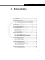
Extensibility ......................................................... 3-1
3.1
Introduction .................................................... 3-3
3.2
Implementing Interfaces ................................... 3-5
3.3
Data Types...................................................... 3-6
3.4
Extension Development Kit ................................ 3-7
3.5
Creating an Extension ....................................... 3-9
3.6
Registering Extensions .....................................3-21
3.7
Extension Interface Details ...............................3-26
3.8
Extension Reaction Kinetics ..............................3-28
3.9
Extension Property Packages ............................3-46
3.10 Extension Unit Operations ................................3-52
3.11 References .....................................................3-80
4
Extension View Editor........................................... 4-1
viii
5
6
7
A
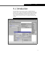
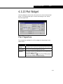
4.1
Introduction .................................................... 4-3
4.2
Using the View Editor........................................ 4-8
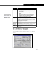
4.3
Widget Properties............................................4-28
User Variables ...................................................... 5-1
5.1
Introduction .................................................... 5-2
5.2
Adding a User Variable...................................... 5-2
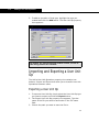
5.3
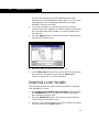
Importing/Exporting User Variables .................... 5-7
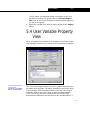
5.4
User Variable Property View............................... 5-9
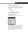
5.5
Data Types.....................................................5-10
5.6
User Variables Tabs .........................................5-13
5.7
Code Editor ....................................................5-20
5.8
User Variable Examples....................................5-22
User Unit Operation .............................................. 6-1
6.1
Introduction .................................................... 6-2
6.2
Adding a User Unit Operation............................. 6-2
6.3
User Unit Op Property View ............................... 6-5
6.4
Dehumidifier Example......................................6-12
Aspen Custom Modeler Operation......................... 7-1
7.1
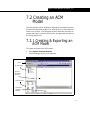
Introduction .................................................... 7-2
7.2
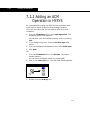
Creating an ACM Model ..................................... 7-3
Customization FAQ ...............................................A-1
A.1
Automation FAQ............................................... A-2
A.2
Extensibility FAQ ............................................ A-10
Index.................................................................... I-1
ix
Introduction
1-1
1 Introduction
1.1 Customization ................................................................................ 2
1.2 Automation & Extensibility............................................................. 3
1.2.1 Automation ............................................................................. 3
1.2.2 Extensions .............................................................................. 4
1.3 Customizing HYSYS........................................................................ 6
1.3.1 HYSYS & the Macro Language Editor ........................................... 7
1.3.2 Programming HYSYS from External Programs............................... 9
1-1
1-2
Customization
1.1 Customization
Unlike its accompanying volumes, the Customization Guide does
not discuss exact procedures for accomplishing tasks within
HYSYS. The purpose of this volume is to demonstrate the
possible simulation technologies that can be created both within
HYSYS and also in addition to the application. HYSYS
incorporates an advanced software architecture and OLE
Technology to provide a component-based framework that can
be easily customized, updated and maintained to meet changing
user requirements.
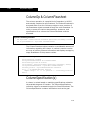
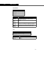
The term customization encompasses several different
approaches for tailoring HYSYS including:
Method
Description
Automation
The use of third party tools such as Visual Basic or the
HYSYS Macro Language Editor to programmatically run
HYSYS.
Extensibility
The creation of custom unit operations, property packages
and kinetic reactions which become part of the simulation
and function as built in HYSYS objects.
The difference between automation and extensibility may not be
explicitly apparent. The difference lies in the environment in
which your personal algorithms are executed. Automation
requires the use of third party software to link to HYSYS in a
client-server relationship. Using this functionality, you can hide
the complexity of a simulation by building a front-end in another
program that allows access to only the important parameters of
the simulation. You can also use HYSYS as a server in your own
applications. HYSYS is an Automation Server, which means that
it can act as an Automation client that can be used to access
HYSYS. Some examples of tools that can access HYSYS are
Microsoft Visual Basic and the VBA component of applications
such as Excel, Word, PowerPoint and Visio. You can also access
HYSYS through programs written in C++.
Extensibility incorporates your custom algorithms in the form of
Extension Property Packages, Extension Unit Operations, and
Extension Reaction Kinetics. The calculations take place within
the calculation sequence of a HYSYS simulation. Extensions can
1-2
Introduction
1-3
be easily distributed to other machines, and they appear as any
other HYSYS object in the program. You could easily develop an
extension, test it, market it and sell it to other HYSYS users as a
third party add-in.
The Customization Guide’s purpose is threefold:
•
•
•
To introduce the user to the functionality of HYSYS
automation and extensibility.
To demonstrate different methods of accessing and using
HYSYS objects.
To provide straightforward examples that teach you the
basics and allow you to begin customizing HYSYS.
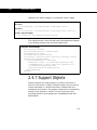
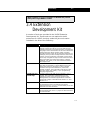
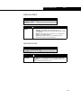
Within the HYSYS environment, several tools are provided so
you can begin writing code for automation and extensions:
For more information on
User Variables and User
Unit Ops see Chapter 5
- User Variables and
Chapter 6 - User Unit
Operation.
Tool
Description
The Macro Language
Editor
An interactive design environment for developing,
testing and executing WinWrap basic scripts.
User Variables and the
User Unit Operation
Allow you to increase the functionality of HYSYS by
creating your own variables or unit operations.
1.2 Automation &
Extensibility
1.2.1 Automation
Automation allows programmers to expose objects within a
program for use by other applications. The exposed objects
provide the means by which different applications can interact
with each other and the operating system. Automation is a
standard based on Microsoft's Component Object Model (COM).
It is not necessary to understand all the intricacies of
Automation or COM in order to utilize the functionality they
provide.
Automation evolved from what was once called OLE, which
stands for Object Linking and Embedding. This allowed you to
take a particular object such as a spreadsheet and embed it into
1-3
1-4
Automation & Extensibility
another object such as a text document. Changes to values in
the spreadsheet would automatically be updated in the text
document. This was a very powerful feature and was available to
users without the added complexity of writing code. It was
simply a matter of cutting and pasting the objects.
Automation is the ability to programmatically interact with an
application through objects exposed by developers of that
application. While HYSYS was being developed, code was added
to expose various objects in the program. By using an
Automation client like Visual Basic, the end user can write the
code to access these objects and interact with HYSYS. The end
user does not need to see the HYSYS source code or even
understand what was required to expose the objects. All that is
required is the knowledge of those objects that are available.
Automation works in a client/server fashion. A server is
something that provides a service that can be used by clients if
they know the proper protocols. HYSYS is an Automation server
application. By writing a little Visual Basic code, it is possible to
send and receive information to and from HYSYS. The exposed
objects make it possible to perform nearly any action that is
accomplished through the HYSYS graphical user interface.
You can use Automation to access COMThermo in HYSYS to
calculate COMThermo properties such as fugacity coefficients, Kvalues, entropy, and enthalpy
1.2.2 Extensions
The HYSYS architecture allows direct extensibility for unit
operations, kinetic reactions, and property packages.
Extensibility can be described as the ability to augment existing
functionality in a direct and seamless manner. Unit operation
extensions look and feel like the existing operations in HYSYS
but the algorithms used by the extension reside in a separate
Windows DLL. Similarly, kinetic reaction extensions and
property package extensions appear seamlessly in the basis
environment.
1-4
Introduction
1-5
A HYSYS extension is typically composed of two distinct and
interdependent components; an ActiveX Server DLL and an
Extension Definition File (EDF). The ActiveX Server DLL contains
the actual code for the extensions and can be created in any
OLE controller language such as Visual Basic, C++, or Delphi.
Nearly any other type of compiled code base can be accessed
via a short wrapper utilizing Visual Basic or C++. The Server is a
program that exposes a class with a set of properties and
methods. For HYSYS extensions, the exposed class contains
methods recognized by HYSYS (for example, when dealing with
a Unit Operation Extension, HYSYS looks for a method named
Initialize that takes one argument and returns a long variable).
The EDF file acts as the interface view within HYSYS as well as
the point for variable declaration and storage. It is created
through the Extension View Editor which is included with your
copy of HYSYS. The View Editor is similar to the tool used by
AspenTech Developers when creating the property views for
HYSYS.
How Does a Hysys Extension Work?
When HYSYS first starts up, it looks in the system registry, at a
specific location, to see if any extensions exist for the machine.
If an extension does exist it is added to the appropriate menu
within HYSYS. Unit operation extensions show up in the UnitOps
property view when the Extensions radio button is selected.
Kinetic reaction extensions show up in the Reactions property
view which is brought up when the Add Rxn button is clicked on
the Reactions tab of the Simulation Basis Manager property
view. Property package extensions show up in the Property
Package Selection group found on the Set Up tab of the Fluid
Package property view.
Once you find the appropriate extension, you can select it and
begin using it as though it were a built-in HYSYS object.
1-5
1-6
Customizing HYSYS
1.3 Customizing HYSYS
HYSYS can be programmatically run from any tool that supports
Automation. You can set up scripts that do repetitive tasks, or
you can set up programs of your own that uses HYSYS as the
calculation engine.
For example, the simulation of a plant can be easily hidden by a
front-end created in Microsoft Excel. This front-end could be a
yield prediction program of some sort that uses a rigorous
simulation underneath. Another example would be a proprietary
equipment sizing program that uses HYSYS to generate fluid
properties for the calculations.
When creating these programs, HYSYS can be run invisibly. You
do not need to know the source of the calculations, nor do you
need to deal with another program on the desktop.
Third party tools are not required to access the automation
capabilities of HYSYS. HYSYS provides an Internal Macro Engine
that supports the same syntax as Microsoft Visual Basic. With
this engine, you can automate tasks in HYSYS without the need
for another program.
1-6
Introduction
1-7
1.3.1 HYSYS & the Macro
Language Editor
For more information on
the Macro Language
Editor, consult the online
help that accompanies
the editor. You can find
the online help in the
Help menu in the Editor’s
menu bar.
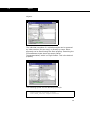
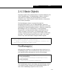
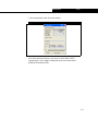
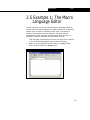
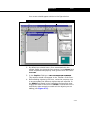
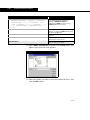
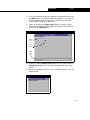
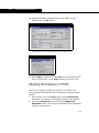
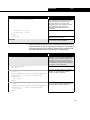
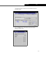
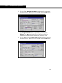
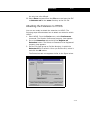
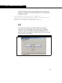
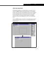
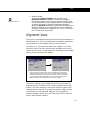
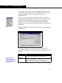
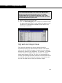
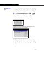
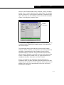
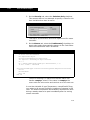
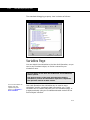
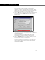
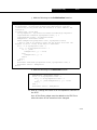
The Macro Language Editor is accessed by selecting the Macro
Language Editor command from the Tools menu in the
Simulation environment.
Figure 1.1
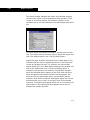
The editor is an interactive design environment for developing,
testing and executing WinWrap Basic automation scripts. The
editor, which uses a syntax that is very similar to Microsoft®’s
Visual Basic, allows you to write code that interacts with HYSYS.
Two objects can be accessed directly from any point in a macro:
•
•
Application
ActiveCase
These special commands allow you to generalize your macros so
that they can be run under many different situations. If you
reference the ActiveCase object, your macro works for any
Simulation Case that is currently open in the HYSYS
environment.
1-7
1-8
Customizing HYSYS
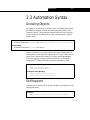
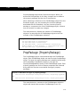
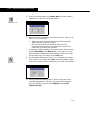
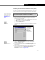
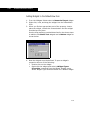
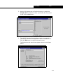
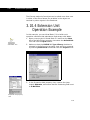
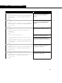
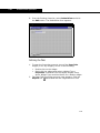
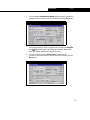
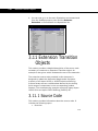
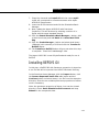
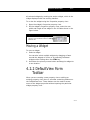
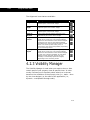
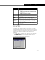
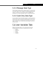
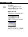
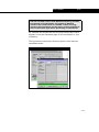
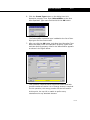
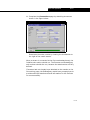
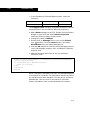
The Macro Language Editor now has two new features:
•
Autocompletion feature, which helps you complete the
user variable codes and helps you debug the program
with flyby evaluation.
For example, if you want to specify “SimulationCase”,
you just need to type up the first few letters of the
variable, and the autocompletion feature will display all
variables with similar names in a drop-down list.
Figure 1.2
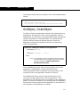
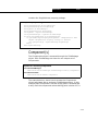
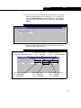
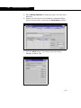
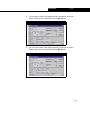
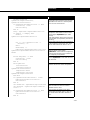
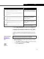
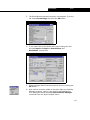
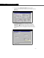
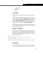
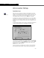
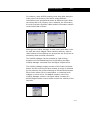
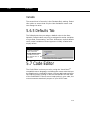
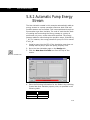
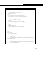
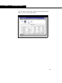
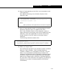
•
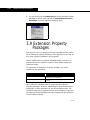
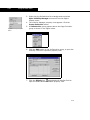
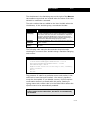
List command feature, which shows you a list of valid
methods or properties depending on the context (type of
expression) you enter.
For example, if you type ActiveObject and type the
period, a drop-down list appears displaying a list of
methods that are applicable to the current object.
Figure 1.3
1-8
Introduction
1-9
1.3.2 Programming HYSYS
from External Programs
HYSYS can be accessed from external programs using
Automation. Programs such as Microsoft Visual Basic and
Microsoft Excel can use HYSYS as a calculation engine, allowing
you to create new applications that invisibly use HYSYS in the
background.
Two HYSYS objects can be created by an external program:
•
•
The HYSYS Application object
The HYSYS SimulationCase object
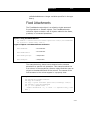
The Application object can be created using one of the
HYSYS.Application ProgIDs. The ProgID determines which
version of HYSYS is activated. Simulation Cases can be created
using the HYSYS.SimulationCase ProgID, or by calling GetObject
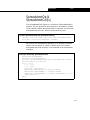
and passing the name of a Simulation Case. For example, this is
how you would create an Application object and a
SimulationCase object from Visual Basic:
Dim
Set
Dim
Set
App as Object
App = CreateObject(“HYSYS.Application”)
HYCASE as Object
HYCASE = GetObject(“c:\hysys\cases\azeocol.hsc”)
Once the Application and Case objects have been created, other
HYSYS objects can be accessed through them. For example,
from the Case's flowsheet object (accessed through the
flowsheet property of the Case), you can create new Process
Streams and Unit Operations.
1-9
1-10
Customizing HYSYS
VBA
Microsoft Excel and related products make use of Visual Basic
for Applications (VBA). VBA is a high level programming
language that is oriented around an object framework and event
driven execution. Visual Basic is termed “visual” because most
applications are created around a graphical interface and Visual
Basic is designed to allow code associated with the interface to
be added easily and intuitively.
Event driven programming is quite different from typical
structured programming. In a structured program, execution
begins at the top of the program and executes for the most part
in a sequential manner. When the bottom of the program is
reached the application exits and is finished. In event driven
programming, the path of execution from the beginning of the
program to the end depends almost entirely on how the end
user interacts with the application.
Visual Basic for Applications is a large sub-set of the Visual Basic
language. It is a macro language that is integrated tightly in to
supporting applications. The syntax and functionality is identical
to straight Visual Basic.
1-10
Automation
2-1
2 Automation
2.1 Introduction................................................................................... 3
2.2 Objects .......................................................................................... 3
2.2.1 Object Hierarchy ...................................................................... 4
2.2.2 HYSYS Type Library .................................................................. 4
2.2.3 Object Browser ........................................................................ 5
2.3 Automation Syntax ........................................................................ 9
2.4 Key HYSYS Objects ...................................................................... 18
2.4.1
2.4.2
2.4.3
2.4.4
2.4.5
2.4.6
2.4.7
2.4.8
HYSYS Object Overview .......................................................... 18
Container Objects................................................................... 18
Basis Objects......................................................................... 23
Oils Objects........................................................................... 27
Stream Objects...................................................................... 30
Operation Objects .................................................................. 44
Support Objects ..................................................................... 48
PFD Objects........................................................................... 54
2.5 Example 1: The Macro Language Editor........................................ 55
2.6 Example 2: Automation in Visual Basic ........................................ 62
2-1
2-2
Introduction
2.1 Introduction
Automation, defined in its simplest terms, is the ability to drive
one application from another. For example, the developers of
Product A have decided in the design phase that it would make
their product more usable if they exposed Product A’s objects,
thereby making it accessible to Automation. Since Products B, C
and D all have the ability to connect to applications that have
exposed objects, each can programmatically interact with
Product A.
In the early product planning stages, the HYSYS development
team had the vision to begin exposing objects. That makes
HYSYS a very powerful and useful tool in the design of hybrid
solutions. Since access to an application through Automation is
language-independent, anyone who can write code in Visual
Basic, C++ or Java, to name three languages, can write
applications that interact with HYSYS. There are a number of
applications that can be used to access HYSYS through
Automation, including Microsoft Visual Basic, Microsoft Excel and
Visio. With so many combinations of applications that can
transfer information, the possibilities are numerous and the
potential for innovative solutions is endless.
2-2
Automation
2-3
2.2 Objects
The key to understanding Automation lies in the concept of
objects. An object is a container that holds a set of related
functions and variables. In Automation terminology, the
functions of an object are called methods and the variables are
called properties.
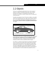
Consider the example of a car. If it were an object, a car would
have a set of properties such as: make, colour, number of doors,
etc. The car object may also have methods such as: turn on,
drive or open hood. By utilizing the properties and methods of a
car object it is possible to define, manipulate and interact with
the object.
Figure 2.1
Object: Car
Properties: Colour, Make, Engine
Methods: Drive, Refuel
Each property of the car is a variable that has a value associated
with it. The colour would be a string or hexadecimal number
associated with a specific colour. The gas mileage would be
single floating point value. Methods are nothing more than
functions and sub-routines associated with the object.
An object is a container that holds all the attributes associated
with it. An object could contain other objects that are logical
sub-set of the main object. The car object may contain other
objects such as engine or tire. These objects would have their
own set of independent properties and methods. An engine
would have properties related to the number of valves and the
size of the pistons. The tires would have properties such as
2-3
2-4
Objects
tread type or model number.
2.2.1 Object Hierarchy
The path that is followed to get to a specific property may
involve several objects. The path and structure of objects is
referred to as the object hierarchy. In Visual Basic the properties
and methods of an object are accessed by hooking together the
appropriate objects through a dot operator (.) function. Each dot
operator in the object hierarchy is a function call. In many cases
it is beneficial to reduce the number of calls by setting
intermediate object variables.
For instance, expanding on our previous example involving the
car, suppose there existed an object called Car and you wanted
to set the value of its engine size. You could approach the
problem in one of two ways.
Direct specification of object property
Car.Engine.Size = 4
Indirect specification of object property
Dim Eng1 as Object
Set Eng1 = Car.Engine.Size
Eng1 = 4
If the Engine size is a property you wanted to access quite often
in your code, using the indirect method of specification may be
easier as it reduces the amount of code thereby reducing the
possibility of error.
2.2.2 HYSYS Type Library
In order to do anything with objects it is first necessary to know
what objects are available. When an application is exposed for
Automation, a separate file is usually created that lists all the
objects and their respective properties and methods. This file is
called the type library and nearly all programs that support
Automation have one of these files available. With the help of an
Object Browser, such as the one built in to MS Excel, you now
have a way to view all the objects, properties, and methods in
2-4
Automation
2-5
the application by examining the type library.
The HYSYS type library reveals over 340 objects that contain
over 5000 combined properties and methods. For every object,
the type library shows its associated properties and methods.
For every property, the type library shows its return type. For
every method, the type library shows what type of arguments
are required and what type of value might be returned.
Accessing a specific property or method is accomplished in a
hierarchical fashion by following a chain of exposed objects. The
first object in the chain should be an object from which all other
objects can be accessed. This object is typically the main
application or one of the open documents. In HYSYS, the
starting objects are the SimulationCase and Application objects.
All other objects are accessible through these two starting
objects.
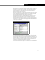
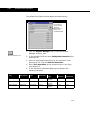
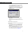
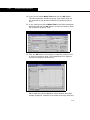
2.2.3 Object Browser
The type library itself does not exist in a form which is
immediately viewable to you. In order to view the type library,
you require the use of an application commonly referred to as
an Object Browser. The Object Browser interprets the type
library and displays the relevant information. Microsoft Excel
and Visual Basic both include a built in Object Browser.
Accessing the Object Browser in
Excel 97/2000/XP
1. Open the Tools menu.
2. Press ALT F11 (or select the Visual Basic Editor option
from Macro group).
3. Within the Visual Basic Editor, open the Tools menu.
4. Select the References command.
5. Select the checkbox next to the HYSYS Type Library.
6. Click the OK button.
2-5
2-6
Objects
7. Open the View menu and select the Object Browser
command (or press F2).
8. Open the Libraries/Workbooks drop-down list and select
HYSYS.
Navigating Through the type Library
This section shows how to navigate through the type library in
order to determine the object hierarchy necessary to access a
particular property. Consider the desired property is the
temperature of a stream called “Feed_Stream”.
The first step is to begin with one of the starting objects. The
Application and SimulationCase objects are the starting points in
HYSYS. You can visualize what is available from the Application
object by picturing the HYSYS application view when the
program is first started. You can do the same with the
SimulationCase object by thinking of all the information
contained within a case. Nearly all the objects of interest are
accessed from the SimulationCase object.
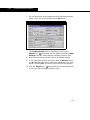
Figure 2.2
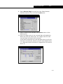
Selecting the SimulationCase object in the browser reveals all of
its related properties and methods. Examining the list of
properties does not reveal any type of stream like object so
there must be a connection through another object. The
properties that are links to other objects can be determined by
looking at the type shown when a property is selected. If the
2-6
Automation
2-7
type shown is not a string, Boolean, variant, double, integer, or
long then it is most likely an object. The object type shown is
found somewhere in the object list and is the next step to
determining the object hierarchy.
With prior experience in HYSYS the flowsheet object is a logical
choice. Selecting the flowsheet object in the object list shows
the associated properties and methods. There is an
EnergyStreams property, a MaterialStreams property, and a
Streams property. All three of these properties are of type
Streams and are therefore objects. In this case some previous
experience in using HYSYS would suggest that MaterialStreams
is the object of interest.
Figure 2.3
The MaterialStreams object is of type Streams. Examining the
Streams object does not reveal any temperature properties. The
Streams object is a collection object, which is simply an object
that is a collection of other objects with some properties and
methods for navigating through the collection.
In this case the Streams object is a collection of ProcessStream
2-7
2-8
Objects
objects.
Figure 2.4
The individual members of a collection object can be accessed
by index number (like an array) or directly by name. Either
approach can be used through the Item property. Examining the
ProcessStream object shows a property called
TemperatureValue, which is of type Double. This is the desired
property.
Figure 2.5
The resulting syntax for the desired property is:
SimulationCase.Flowsheet.Streams.
Item(“Feed_Stream”).TemperatureValue
2-8
Automation
2-9
2.3 Automation Syntax
Declaring Objects
An object in Visual Basic is another type of variable and should
be declared. Objects can be declared using the generic type
identifier object. The preferred method however uses the type
library reference to declare the object variables by an explicit
object name.
Early Binding:
Dim|Public|Private objectvar As ObjectName as specified in the type library
Late Binding:
Dim|Public|Private objectvar As Object
Once a reference to the type library has been established, the
actual name of the object as it appears in the type library can be
used. This is called early binding. It offers some advantages
over late binding, including speed and access to Microsoft’s
Intellisense® functionality when using Visual Basic or VBA.
Example: Late Binding
Public hyCase As Object
Public hyStream As Object
Example: Early Binding
Public hyCase As SimulationCase
Public hyStream As ProcessStream
Set Keyword
Connections or references to object variables are made by using
the Set keyword.
Syntax:
Set objectvar = object.[object…].object | Nothing
2-9
2-10
Automation Syntax
The example below assumes hycase is set to the SimulationCase
object.
Example: Set
Dim hyStream As ProcessStream
Set hyStream = hyCase.Flowsheet.MaterialStreams.Item(0)
GetObject, CreateObject
In order to begin communication between the client and server
applications, an initial link to the server application must be
established. In HYSYS this is accomplished through the starting
objects: Application or SimulationCase. The typical ActiveX
object structure supplies a starting object to access the
application interface and another to access the documents
within the application.
Syntax for creating an instance of an application:
CreateObject(class)
GetObject([pathname] [, class])
where:
class = the starting object as specified in the type library.
In HYSYS there are two objects that can be used for
the class statement: HYSYS.Application or
HYSYS.SimulationCase.
The CreateObject function starts a new instance of the main
application. CreateObject is used in HYSYS with the
HYSYS.Application class as specified in the type library. This
connects to the main application interface of HYSYS.
The GetObject function opens a specific document in the
currently running instance of the server application. If the
application is not running then a new instance of the application
starts. If a specific document is not specified with the GetObject
function the current instance of the application is connected or a
new instance of the application is started.
2-10
Automation
2-11
For application objects or document objects the codes are shown
below:
Example: CreateObject and GetObject
Set applicationobj = CreateObject(“HYSYS.Application”)
or
Set applicationobj = GetObject(, “PROGRAM.Application”)
Set documentobj = GetObject(“c:\filepath”, “PROGRAM.Document”)
In the example below, hyCase is declared as type object so it is
using late binding. The hyCase variable is connected to a HYSYS
case by using the GetObject function and the Set keyword. The
second argument in the GetObject function is the starting
object.
Example 1: Starting a HYSYS case through Automation
Dim hyCase As Object
Set hyCase = GetObject(“c:\samples\c-2.hsc”, “HYSYS.SimulationCase”)
The second example is identical to the first except that the
object variable hyCase is declared using the actual object name
as it appears in the type library. This assumes that a reference
to the type library has already been set.
Example 2: Starting a HYSYS case through Automation
Dim hyCase As SimulationCase
Set hyCase = GetObject(“c:\samples\c-2.hsc”, “HYSYS.SimulationCase”)
The third example uses early binding in the object declaration.
The CreateObject command is used to bring up an instance of
HYSYS. The starting object here is the HYSYS.Application object
since a case is not initially being opened. The SimulationCases
object is accessed through the Application object and the Open
method of SimulationCases is used to bring up a specific HYSYS
case. The hyCase object is set to the active case through the
2-11
2-12
Automation Syntax
ActiveDocument property of hyApp.
Example 3: Starting a HYSYS case through Automation
Dim hyCase As SimulationCase
Dim hyApp As HYSYS.Application
Set hyApp = CreateObject(“HYSYS.Application”)
hyApp.SimulationCases.Open(“c:\HYSYS\samples\c-2.hsc”)
Set hyCase = hyApp.ActiveDocument
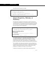
Object Properties, Methods, &
Hierarchy
The sequence of objects is set through a special dot function.
Properties and methods for an object are also accessed through
the dot function. It is preferable to keep the sequence of objects
to a minimum since each dot function is a call to link between
the client and the server application.
Syntax for setting objects and accessing properties:
Set objectvar = object.[object.object...].object
Variable = object.[object.object...].property
Syntax for accessing methods:
Function Method
returnvalue = object.method([argument1, argument2,...])
Sub-routine Method
object.method argument1, argument2
The object hierarchy is an important and fundamental concept
for utilizing Automation. A particular property can only be
accessed by following a specific chain of objects. The chain
always begins with either the Application or SimulationCase
object and ends with the object containing the desired property.
The methods of an object are accessed in the same fashion as
properties by utilizing the dot function. A method for a particular
object is nothing more then a function or sub-routine whose
behaviour is related to the object in some fashion.
Typically the methods of an object require arguments to be
2-12
Automation
2-13
passed when the method is called. The type library provides
information about which arguments are necessary to call a
particular method. A function returns a value.
Sub-routines in Visual Basic do not require parentheses
around the argument list.
The example below, starts up HYSYS and opens a specific case.
The temperature value of a specific stream is then obtained. The
temperature value is obtained through a connection of three
objects: SimulationCase, Flowsheet, and MaterialStreams.
Example 1: Accessing HYSYS object properties
Dim hyCase As SimulationCase
Dim TempVal As Double
Set hyCase = GetObject(“c:\c-2.hsc”,”HYSYS.SimulationCase”)
TempVal = hyCase.Flowsheet.MaterialStreams.Item(0).TemperatureValue
MsgBox TempVal
The example below, also accesses the temperature value of a
specific stream but creates some intermediate objects so that
when the temperature value is actually requested the chain of
objects only contains one object.
Example 2: Accessing HYSYS object properties
Dim hyCase As SimulationCase
Dim hyFlowsheet As Flowsheet
Dim hyStream As ProcessStream
Dim TempVal As Double
Set hyCase = GetObject(“c:\samples\c-2.hsc”, “HYSYS.SimulationCase”)
Set hyFlowsheet = hyCase.Flowsheet
Set hyStream = hyCase.Flowsheet.MaterialStreams.Item(0)
TempVal = hyStream.TemperatureValue
MsgBox TempVal
Collection Objects
A collection object is an object that contains a set of other
objects. This is similar to an array of objects. The difference
between an array of objects and a collection object is that a
2-13
2-14
Automation Syntax
collection object contains a set of properties and methods for
navigating and manipulating the objects in the collection.
Syntax: Typical Properties of a Collections Object
Item(index)
Accesses a particular member of the collection by
number.
Index(name)
Determines the index number for a member in
the collection by its name.
Count
Returns the number of objects in the collection.
Syntax: Enumeration of Objects
For Each element In group
[statements]
[Exit For]
[statements]
Next [element]
The most commonly used properties are:
•
•
•
Index. The Index property takes in a name and returns
a number value associated with the object’s name.
Item. The Item property takes an index value or name
or integer number as the argument and returns a
reference to the object within the collection.
Count. The Count property returns the number of items
in the collection.
A special type of For loop, called For Each, is available for
enumerating through the objects within the collection. The For
Each loop provides a means for enumerating through the
collection without explicitly specifying how many items are in
the collection. This helps avoid having to make additional
function calls to the Count and Item properties of the collection
object in order to perform the same type of loop.
The example below, connects to a collection of streams by
setting the hyStreams object. A For loop is created that uses the
Count and Item properties of a collection in order to display a
property view that contains the stream name. The items in the
collection are indexed beginning with 0. The Count property
returns the actual number of objects in the collection so it is
2-14
Automation
2-15
necessary to subtract one in order to access all the objects in
the collection.
Example 1: Accessing Collection Objects
Dim
Dim
Set
For
hyStreams As Streams
hyStream As ProcessStream
hyStreams = hyCase.Flowsheet.MaterialStreams
j = 0 To hyStreams.Count - 1
MsgBox hyStreams.Item(j).name
Next j
The example below, is identical to the first example except that
a For Each loop is used instead of the standard For loop in order
to enumerate through the Streams collection.
Example 2: Accessing Collection Objects
Dim
Dim
Set
For
hyStreams As Streams
hyStream As ProcessStream
hyStreams = hyCase.Flowsheet.MaterialStreams
Each hyStream In hyStreams
MsgBox hyStream.name
Next hyStream
Variants
A property can return a variety of variable types. Values such as
temperature and pressure are returned as doubles or 32-bit
floating-point values. The stream name property returns a string
value. Visual Basic provides an additional variable called a
variant. A variant is a variable that can take on the form of any
type of variable including, Integers, Double, String, Array, and
Objects.
If the property of an object returns an array whose size can vary
depending upon the case, then a variant is used to access that
value. For example, the ComponentMassFractionValue property
of a ProcessStream returns an array of doubles sized to the
number of components associated with that stream.
In Visual Basic, if a variable is not explicitly declared then it is
2-15
2-16
Automation Syntax
implicitly a variant. Variants have considerably more storage
associated with their use, so for a large application it is good
practice to limit the number of variants being used. It is also just
good programming practice to explicitly declare variables
whenever possible.
The dimensions of the array depend upon what property is being
called. The following table lists the most common properties
that return arrays and what is the dimension of the array.
Common Variant of HYSYS
Returning Property
Component Mass Fractions
One Dimensional array
Column Component Fraction Values
Two Dimensional array
Interaction Parameters
Two Dimensional array
The example below, shows how to get an array of stage
pressures in a column.
Example 1: Using Variants in HYSYS
Dim hyOp As ColumnOp
Dim hyStagePressure As Variant
Set hyOp = hyCase.Flowsheet.Operations(“ColumnOp”).Item(0)
hyStagePressure = hyOp.PressureValues
For j = 0 To UBound(hyStagePressure)
MsgBox “Stage “ & j +1 & “ Pressure = “ & hyStagePressure(j)
Next j
The hyOp object is declared as a ColumnOp as specified in
the type library. The operations collection is filtered to only
include columns by using the word “ColumnOp”. HyOp is set
to the first column in the operations collection.
HyStagePressure is set equal to an array of doubles returned
by the ColumnOp object. Since the number of stages in this
column may not be known the Ubound function is used to
determine the upper bound of the one dimensional array. A
property view prints out the pressure value for each stage in
the column.
The example below, accesses the VapourComponentFraction
2-16
Automation
2-17
property of a column.
Example 2: Using Variants in HYSYS
Dim hyOp As ColumnOp
Dim hyStageCompFrac As Variant
Set hyOp = hyCase.Flowsheet.Operations(“ColumnOp”).Item(0)
hyStageCompFrac = hyOp.VapourComponentFraction
For j = 0 To UBound(hyStageCompFrac,2)
MsgBox “Stage “ & j +1 & “ Component 1 Vapour Fraction = “ &
hyStageCompFrac(0,j)
Next j
The array is set to hyStageCompFrac. This array is twodimensional. The first dimension represents the components
in the systems as specified in the fluid package. The second
dimension represents the stages in the column. A property
view displays the vapour fraction of component 1 for each
stage of the column.
2-17
2-18
Key HYSYS Objects
2.4 Key HYSYS Objects
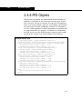
2.4.1 HYSYS Object Overview
There are over 340 automation objects exposed in HYSYS.
These objects collectively contain of over 5000 properties and
methods. One of the more time consuming and difficult tasks in
learning to use Automation objects is determining what objects
are available and how to get at a property of interest.
The following sub-sections are designed to explore key HYSYS
objects in more detail and hopefully provide the necessary
information required to access nearly any object, property, or
method in HYSYS. Because of the large number of key objects
and their attributes, the objects within HYSYS have been divided
in seven distinct categories. These object categories are:
Container Objects, Support Objects, Oil Objects, Basis Objects,
Stream Objects, Operation Objects, Extension Objects, and PFD
Objects.
2.4.2 Container Objects
This category refers to objects that house other objects or form
the basis from which a large number of objects are derived. For
instance, the Application object can contain several
SimulationCase objects. The SimulationCase object contains all
the remaining objects associated with that case. The flowsheet
object is a repository for all the streams and unit operations of
the case. The flowsheet can also contain another flowsheet,
Application or SimulationCase.
Application and SimulationCase
The Application object is the top most object in HYSYS and
represents the HYSYS program itself. From the Application
object, nearly all the objects listed in the HYSYS type library can
be accessed. The SimulationCase object is the starting object for
2-18
Automation
2-19
accessing or opening specific simulation cases.
Syntax: Connecting to the Application
Set hyApp = CreateObject(“HYSYS.Application”)
Syntax: Connecting to the Simulation Case
Through GetObject
Set hyCase = GetObject(“filepath”, “HYSYS.SimulationCase”)
Through the Application Object
Set hyCase = hyApp.ActiveDocument
Through SimulationCases Collection Object
Set hyCase = hyApp.SimulationCases.Item(“CaseName”)
2-19
2-20
Key HYSYS Objects
Using GetObject and CreateObject
The SimulationCase object and the Application object can be
created directly through the GetObject function in Visual Basic.
The CreateObject function can also be used to access the
Application object. In general the starting object for most
Automation procedures is the SimulationCase object.
The example below, uses the GetObject function to start-up
HYSYS with the specified case.
Example 1: Accessing the HYSYS Container Objects
Dim hyCase As SimulationCase
Set hyCase = GetObject(“c:\hysys\cases\c-2.hsc”, “HYSYS.SimulationCase”)
The example below, connects to the HYSYS Application object
and enumerates through all the currently open cases. If a case
name matches the specified string then a SimulationCase object
is set to that case. The FOR loop cycles through the list of cases
based on the count value. In Visual Basic arrays and collections
are base 0 unless otherwise specified.
Example 2: Accessing the HYSYS Container Objects
Dim hyApp As HYSYS.Application
Dim hyCases As SimulationCases
Dim hyCase As SimulationCase
Set hyApp = CreateObject(“HYSYS.Application”)
Set hyCases = hyApp.SimulationCases
For j = 0 To hycases.Count - 1
If hycases.Item(j).name = “ethanol.hsc” Then
Set hyCase = hyCases.Item(j)
End If
Next j
2-20
Automation
2-21
Starting a Particular Version of HYSYS
To start a particular version of HYSYS via OLE, use one of the
following HYSYS.Application ProgIDs.
ProgID
Description
HYSYS.Application
Activates the most currently registered
version of HYSYS.
HYSYS.Application.V7.3
Activates HYSYS V7.3 as long as it is
registered.
HYSYS.Application.Latest
Activates the latest version of HYSYS that is
registered.
HYSYS.Application.NewInstance
Starts a new instance of the most currently
registered version of HYSYS.
HYSYS.Application.NewInstance.V7.2
Starts a new instance of HYSYS 2006 as long
as it is registered. Notice that in this case
V7.2 may not be the latest registered version
of HYSYS.
HYSYS.Application.NewInstance.Latest
Starts a new instance of the latest version of
HYSYS that is registered.
Some ProgIDs activate the most currently registered version of
HYSYS. HYSYS 2006 and later versions register only at
installation. You can manually register and un-register HYSYS
2006 and after using the following commands:
HYSYS /regserver
HYSYS /unregserver
If you open a case using GetObject (“casename.hcs”), the case
will open with the version of HYSYS that was last registered.
VB6 supports an additional parameter for GetObject that allows
the case to be open in the version specified. For example, this
code would open the case in HYSYS V7.3:
GetObject (“case.hsc”, “HYSYS.SimulationCase.V7.3”)
Flowsheet(s)
The main flowsheet object is accessed through the
SimulationCase object. The flowsheet object is a container of all
the ProcessStream and Operations objects as well as a link to
the FluidPackage object associated with that flowsheet. Each
flowsheet and sub-flowsheet can have its own fluid package and
2-21
2-22
Key HYSYS Objects
likewise its own property package and set of components. Subflowsheets can be accessed from the main flowsheet object
through the flowsheet collection object.
Syntax: Flowsheet Object
Dim hyFlowsheet As Flowsheet
Set hyFlowsheet = hyCase.Flowsheet
The above syntax, shows how to connect to the flowsheet object
of the HYSYS case. This assumes the hyCase variable is already
set to the SimulationCase object in HYSYS. The remaining
examples in this module assume a SimulationCase object
'hyCase' is already set.
The example below, shows how to connect to a sub-flowsheet of
a flowsheet. Sub-flowsheets are accessed from the main
flowsheet. The main flowsheet is accessed through the
SimulationCase.
Example: Connecting Flowsheets
Dim
Dim
Dim
Set
Set
Set
hyFlowsheet As Flowsheet
hySubFlowsheets As Flowsheets
hySubFlowsheet As Flowsheet
hyFlowsheet = hyCase.Flowsheet
hySubFlowsheets = hyFlowsheet.Flowsheets
hySubFlowsheet = hySubFlowsheets.Item(0)
2-22
Automation
2-23
2.4.3 Basis Objects
The Basis objects refer predominantly to objects handled by the
HYSYS BasisManager. The BasisManager object in HYSYS is
responsible for handling the global aspects of a HYSYS
simulation case. These objects include reactions, components,
and property packages.
The BasisManager object is accessed through the
SimulationCase object. From the BasisManager object the
FluidPackages and HypoGroups collection objects are accessed.
Changing the objects accessed directly or indirectly through the
BasisManager such as FluidPackages, PropertyPackage,
Components, and Hypotheticals requires notification to the
HYSYS simulation environment. The BasisManager object
contains methods that allow changes to the basis to take place
smoothly. The following methods must be used on the outer
limits of any code that makes changes to Basis objects.
Syntax: Changing Basis Values
SimulationCase.BasisManager.StartBasisChange
... changes to components, interaction parameters, reactions, etc.
SimulationCase.BasisManager.EndBasisChange
FluidPackage(s)
Although both examples of syntax shown below lead you to a
FluidPackage object, there are differences that exist which are
only apparent when attempting to use the fluid package.
Syntax: Accessing FluidPackages
From the BasisManager
SimulationCase.BasisManager.FluidPackages.Item(0)
From the Flowsheet
SimulationCase.Flowsheet.FluidPackage
The FluidPackages object returned by the BasisManager object
is a collection object containing all FluidPackage objects in a
case. Each FluidPackage object can have its own
2-23
2-24
Key HYSYS Objects
PropertyPackage object and Components object. When you
access the fluid package in this way, changes can be made to
the property package and the list of components.
When obtaining a reference to the FluidPackage object from the
flowsheet object, you are accessing the one fluid package
associated with the flowsheet. You can view the property
package or component list of the FluidPackage object, however
you are not able to make any changes.
The example below, displays the number of FluidPackage
objects in a case and sets a FluidPackage object to the first
member of the FluidPackages collection.
Example: FluidPackage
Dim hyFluidPackages As FluidPackages
Dim hyFluidPackage As FluidPackage
Set hyFluidPackages = hyCase.BasisManager.FluidPackages
MsgBox “Number of Fluid Packages = “ & hyFluidPackages.Count
Set hyFluidPackage = hyFluidPackages.Item(0)
PropPackage (PropertyPackage)
The PropPackage object is accessed through the FluidPackage
object. Each FluidPackage object can have a single PropPackage
object. The type of property package can be determined through
the PropPackage TypeName property or through the
PropertyPackageName property of the FluidPackage object. Each
property package has a set of unique properties and methods
along with the common ones shared among all property
packages.
Syntax to determine the type of property package
SimulationCase.BasisManager.Fluidpackages.Item(0).PropPackage.TypeName
or
SimulationCase.BasisManager.Fluidpackages.Item(0).PropertyPackageName
The example below, connects to the FluidPackages collection
object and checks each member FluidPackage to see if it
2-24
Automation
2-25
contains the PengRobinson property package.
Example: Property Package
Dim hyFluidPackages As FluidPackages
Dim hyFluidPackage As FluidPackage
Dim hyBasis As BasisManager
Dim hyPropPackage As PropPackage
Set hyBasis = hyCase.BasisManager
Set hyFluidPackages = hyBasis.FluidPackages
For Each hyFluidPackage In hyFluidPackages
If hyFluidPackage.PropertyPackageName = “PengRobinson” Then
MsgBox “PengRobinson Property Package is Present”
Set hyPropPackage = hyFluidPackage.PropPackage
End If
Next hyFluidPackage
Component(s)
The Components object is accessed through the FluidPackage
object. Each FluidPackage can have its own unique set of
Components.
Syntax for accessing components
From the BasisManager
SimulationCase.BasisManager.FluidPackages.Item(0).Components
From the Flowsheet
SimulationCase.Flowsheet.Components
The example below, shows how to access the Components
object associated with a particular FluidPackage object. In this
example each component's normal boiling point is checked and
a tally of all the components whose boiling point is below 0°C is
2-25
2-26
Key HYSYS Objects
counted.
Example: Components
Dim numComp As Integer
Dim hyFluidPackage As FluidPackage
Dim hyBasis As BasisManager
Dim hyComponents As Components
Dim hyComponent As Component
Set hyBasis = hyCase.BasisManager
Set hyFluidPackage = hyBasis.FluidPackages.Item(0)
Set hyComponents = hyFluidPackage.Components
numComp = 0
For Each hyComponent In hyComponents
If hyComponent.NormalBoilingPointValue < 0 Then
numComp = numComp + 1
End If
Next hyComponent
MsgBox numComp & “ components have NBP below 0"
Hypotheticals
The HypoGroups collection object is accessed from the
BasisManager. This object contains a collection of HypoGroup
objects, each of which provides access to a HypoComponents
object. A HypoComponent can be entirely specified through
Automation and added to a HYSYS simulation case. Methods for
the HypoComponent object are used to estimate properties
based on the minimum data requirement.
Syntax: Hypotheticals
SimulationCase.BasisManager.HypoGroups.Item(0).HypoComponents.Item(0)
The example below, adds a hypothetical component and sets its
boiling point value in order to estimate the remaining properties.
The StartBasisChange and EndBasisChange methods are
2-26
Automation
2-27
invoked prior to adding this hypothetical to the case.
Example: HypoComponent
Dim hypGroups As HypoGroups
Dim hypoComp As Object
hyCase.BasisManager.StartBasisChange
Set hypGroups = hyCase.BasisManager.HypoGroups
hypGroups.Add “myhypo”
hypGroups.Item(“myhypo”).HypoComponents.Add “mycomponent”, “userhypo”
Set hypoComp =
hypGroups.Item(“myhypo”).HypoComponents.Item(“mycomponent*”)
hypoComp.NormalBoilingPointValue = 300
hypoComp.Estimate
MsgBox hypoComp.NormalBoilingPointValue
hyCase.BasisManager.EndBasisChange
Hypotheticals have a * appended to the name once they are
created.
2.4.4 Oils Objects
Oils objects refer to the objects accessed through the Oil
Manager. The OilManager object is set through the
BasisManager and contains Assay and Blend objects.
OilManager
Set through the BasisManager, the OilManager object provides
access to the oils environment. Like changes made to the
objects accessed through the BasisManager, notification to the
simulation environment is required when modifying assays or
blends. This is accomplished by calling the StartOilChange and
EndOilChange methods. Calling the StartOilChange method
before calling the StartBasisChange method by default causes
the StartBasisChange method to be invoked.
2-27
2-28
Key HYSYS Objects
Example: Accessing the Oil Manager Environment
Public hyOil As OilManager
hyCase.BasisManager.StartBasisChange
hyCase.BasisManager.StartOilChange
Set hyOil = hyCase.BasisManager.OilManager
'//code to manipulate oil manager objects
hyCase.BasisManager.EndOilChange
hyCase.BasisManager.EndBasisChange
Assays and Blends are not estimated until the EndOilChange
method is invoked.
AssaysCollection & Assays
The AssaysCollection object is accessed through the OilManager
object and contains the assay objects available within a
particular HYSYS case. There are eight types of assays available
and each of them has a specific set of properties and methods.
AssayTypes:
•
•
•
•
at_ASTMD2887 = 4
at_BulkPropertiesOnly = 7
at_Chromatograph = 5
at_D1160 = 2
•
•
•
•
at_D86 = 1
at_D86D1160 = 3
at_EFV = 6
at_TBP = 0
The properties associated with the hypocomponents generated
by the OilManager can be accessed through the Assay object.
Syntax: Assays
Referencing a Collection
Set hyAssays = hyCase.BasisManager.OilManager.Assays
Referencing a Member
Set hyAssay = hyCase.BasisManager.OilManager.Assays.Item(“name”)
Adding an Assay
hyCase.BasisManager.OilManager.Assays.Add “name”, AssayType
2-28
Automation
2-29
Below is an example on creating an assay.
Example: Creating Assays
Dim hyAssay As AssayTBP
Dim hyBasis As BasisManager
Set hyAssay = hyBasis.OilManager.Assays.Add(“AssayName”, “TBP”)
With hyAssay
.Basis = ab_LiquidVolumeFraction
.BulkMolecularWeight = 300
.BulkMassDensity.SetValue 783, “API”
Dim hyValue As Variant
Dim hyPercent As Variant
hyPercent = Array(0,10,20,30,40,50,60,70,80,90,98)
hyValue =
Array(26.67,123.89,176.11,221.11,275,335,399,490.56,590.56,691.67,
795.56)
.AssayPercentForBoilingTemperature = hyPercent
.BoilingTemperatureValue = hyValue
.Calculate
End With
Blend(s)
Blends are created through the BasisManager and can be
completed by specifying at least one assay. Multiple assays can
be used in a blend as long as flow rates for each of the assays is
specified. A large number of blend properties for the
hypocomponents created can be viewed.
Syntax for Blends
Referencing a Collection
Set hyBlends = hyCase.BasisManager.OilManager.Blends
Referencing a Member
Set hyBlend = hyCase.BasisManager.OilManager.Blend.Item(“blendname”)
Adding Assay to Blend
HyBlend.AddAssay “AssayName”
Installing to a ProcessStream
hyBlend.InstallIntoStream “StreamName”
The example below, creates a blend, assigns one assay to the
blend, and then prints out the TBP values for the blend. The
2-29
2-30
Key HYSYS Objects
blend is also assigned to a stream in the HYSYS case.
Example: Blends
Dim hyBlend As Blend
'//create blend and assign assay
Set hyBlend = hyBasis.OilManager.Blends.Add(“BlendName”)
hyBlend.AddAssay “AssayName”
'//print out some properties
Dim hyVar As Variant
hyvar = hyBlend.TrueBPTemperatureValue
For i = 0 To UBound(hyVar)
Debug.Print hyVar(i)
Next i
hyBlend.InstallIntoStream “Blend_Stream”
2.4.5 Stream Objects
The main objects of the stream category are the ProcessStream
and Fluid objects. The Fluid object is a type of Stream object
that is not connected to operations but can be derived from a
ProcessStream. The Fluid object can be manipulated without
effecting the operations and streams within the case. The
ProcessStream object can be accessed from either the flowsheet
or the operation to which it is connected.
ProcessStream
The Streams object is a collection object returned by the
flowsheet. The Streams collection contains one or more
ProcessStream objects. There are approximately 124 properties
associated with the ProcessStream, including attributes such as
temperature, pressure, density, and viscosity. These properties
return values of type Double. The ProcessStream object also
returns arrays as variants for properties such as
ComponentMassFraction.
The Fluid object contains a similar set of properties and
2-30
Automation
2-31
methods.
Syntax for accessing the ProcessStream object
By Name
SimulationCase.Flowsheet.MaterialStreams(“streamname”)
SimulationCase.Flowsheet.MaterialStreams.Item(“streamname”)
By Index
SimulationCase.Flowsheet.MaterialStreams.Item(j)
In most instances the collection object and member object of
the collection have nearly similar names. The name of the
collection object is normally the member name with an “s” at
the end. The Streams collection is an exception to this
statement, since it contains a collection of ProcessStream
objects. The flowsheet returns three stream collections;
MaterialStreams, EnergyStreams, and Streams. All three stream
collections accessed through the flowsheet are Streams objects.
The difference between the Streams collection objects relates to
how the member ProcessStream objects are filtered.
The example below, shows how to access a particular stream in
the system by index and how to retrieve the temperature value.
The remaining properties are accessed in a similar fashion.
Example 1: ProcessStream
Dim hyFlowsheet As Object
Dim hyStream As Object
Set hyFlowsheet = hyCase.Flowsheet
Set hyStream = hyFlowsheet.MaterialStreams.Item(0)
MsgBox “Stream Temperature = “ & hyStream.TemperatureValue
The example below, shows how to access the MassFractionValue
for each component in the stream. An array of doubles is
returned to the variant hyCompFrac. The Ubound function is
used to determine the upper bound of the array and thus the
number of components. A separate object is set for the
component collection. The indexing between the array of mass
fractions and the list of components in the FluidPackage is
identical so it is easy enough to match the values with the
2-31
2-32
Key HYSYS Objects
appropriate components.
Example 2: ProcessStream
Dim hyFlowsheet As Flowsheet
Dim hyStream As ProcessStream
Dim hyComponents As Components
Dim hyCompFrac As Variant
Set hyFlowsheet = hyCase.Flowsheet
Set hyComponents = hyCase.BasisManager.FluidPackages.Item(0).Components
Set hyStream = hyFlowsheet.MaterialStreams.Item(2)
hyCompFrac = hyStream.ComponentMassFractionValue
For j = 0 To UBound(hyCompFrac)
MsgBox “Component “ & hyComponents.Item(j) & “ Mass Fraction = “ &
hyCompFrac(j)
Next j
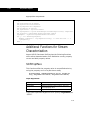
Additional Functions for Stream
Characterization
Aspen HYSYS Petroleum Refining has the following functions
which allow characterization from distillation curves, property
curves and bulk property values.
ShiftPropIFace
This function shifts the property value to a specified value by
using the property curve of a petroleum assay.
ShiftPropIFace (szRefAssayName As String, PropKey As
Long, TargetPFDif As Double, TargetValue As Double)
Input Arguments:
szAssayName
Petroleum Assay name
PropKey
Property Key
TargetPFDif
Difference between target property value and
current property value
TargetValue
Target value of property
If you have specified TargetPFDif then specify TargetValue as
-32767.
2-32
Automation
2-33
If you have specified TargetValue then specify TargetPFDif as
-32767.
A Petroleum Assay name (specified as szAssayName) must exist
in the Petroleum Assay Manager. This assay must use the same
fluid package as the stream.
Example:
feed.ShiftPropIFace "Arab Light", 2004, -32767, 250
The above function specifies the feed stream molecular weight
(property key = 2004) as 250. This function will use the initial
property of the assay “Arab Light”.
ShiftPropCurveIFace
This function shifts the property value to a specified value by
using the property curve specified by user.
ShiftPropCurveIFace (myPropKey As Long, numOfData As
Long, vtTemp As Variant, vtProp As Variant, bulkVal As
Double)
Input Arguments:
myPropKey
Property Key
numOfData
Number of property curve data points
vtTemp
An array of TBP end points (in Kelvin)
vtProp
An array of Property values corresponding to
TBP end points
bulkVal
Bulk Value of property (Aspen HYSYS Petroleum
Refining, default units)
Example:
Dim
Dim
Dim
Dim
vtTargetTemps(6) As Double
vtTargetYields(6) As Double
sulKey As Integer
sulBulk As Double
vtTemp1(0)
vtTemp1(1)
vtTemp1(2)
vtTemp1(3)
vtTemp1(4)
=
=
=
=
=
273.15
573.15
773.15
973.15
1073.15
2-33
2-34
Key HYSYS Objects
vtTemp1(5) = 1173.15
vtProp1(0) = 0.01
vtProp1(1) = 0.03
vtProp1(2) = 0.2
vtProp1(3) = 2
vtProp1(4) = 3
vtProp1(5) = 5
sulKey = 11029
sulBulk = 2
feed.ShiftPropCurveIFace sulKey, 6, vtTemp1, vtProp1,
sulBulk
In the above example, the sulfur property of the feed stream is
shifted to the value 2.0. The algorithm will use 6 data points
(vtTemp1 as TBP end Points and vtProp1 as Property Value).
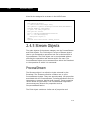
ManipulateCompositionIFace
This function takes in distillation information and light end yield
information and determines the composition of a stream.
ManipulateCompositionIFace (bsCompBasisVarType As String,
bsTargetDistType As String, vtTargetTemps As Variant,
vtTargetYields As Variant, vtTargetLEComp As Variant,
vtTargetLECompId As Variant)
Inputs:
bsCompBasisVarType
Composition Basis (“VolFrac”, “MassFrac” or
“MoleFrac”)
bsTargetDistType
Distillation Basis ( “TBP”, “D86”, “D2887” or
“D1160”)
vtTargetTemps
Distillation temperature end points (in degree
C)
vtTargetYields
Cumulative percentage distillation yields (as in
basis bsCompBasisVarType)
vtTargetLEcomp
Fractional light end yields (as in basis
bsCompBasisVarType) for all the components
present in the stream
vtTargetLECompId
Light end component IDs (Component Index for
all the components present in the stream)
Before execution of this function, feed composition must be
empty.
2-34
Automation
2-35
Example:
Dim x As Variant
Dim intI As Integer
Dim
Dim
Dim
Dim
bsCompBasisVarType As String
bsTargetDistType As String
vtTargetTemps(6) As Double
vtTargetYields(6) As Double
Dim vtTargetLEcomp(37) As Double
Dim vtTargetLEcompId(37) As Double
bsCompBasisVarType = "VolFrac"
bsTargetDistType = "dtTBP"
// these are TBP temperatures in C
vtTargetTemps(0) = 100.01
vtTargetTemps(1) = 200.01
vtTargetTemps(2) = 350.01
vtTargetTemps(3) = 500#
vtTargetTemps(4) = 650
vtTargetTemps(5) = 800
vtTargetTemps(6) = 900
// these are Vol% yield
vtTargetYields(0) =
vtTargetYields(1) =
vtTargetYields(2) =
vtTargetYields(3) =
vtTargetYields(4) =
vtTargetYields(5) =
vtTargetYields(6) =
corresponding to above temperatures
10
25
50
70
80
90
100
For intI = 0 To 37
vtTargetLEcomp(intI) = 0
Next
vtTargetLEcomp(4) = 0.0001 ‘ Methane
vtTargetLEcomp(6) = 0.0002 ‘ Ethane
// these are light ends component ids
vtTargetLEcompId(0)
vtTargetLEcompId(1)
vtTargetLEcompId(2)
vtTargetLEcompId(3)
vtTargetLEcompId(4)
vtTargetLEcompId(5)
=
=
=
=
=
=
20
13
21
28
1
23
‘
‘
‘
‘
‘
‘
Hydrogen
Nitrogen
CO
O2
Methane
Ethylene
2-35
2-36
Key HYSYS Objects
vtTargetLEcompId(6) = 2 ‘ Ethane
vtTargetLEcompId(7) = 14 ‘ CO2
vtTargetLEcompId(8) = 15 ‘ H2S
vtTargetLEcompId(9) = 55 ‘ Propene
vtTargetLEcompId(10) = 3 ‘ Propane
vtTargetLEcompId(11) = 4 ‘ i-Butane
vtTargetLEcompId(12) = 60 ‘ i-Butene
vtTargetLEcompId(13) = 56 ‘1-Butene
vtTargetLEcompId(14) = 58 ‘13-Butadiene
vtTargetLEcompId(15) = 5 ‘n-Pentane
vtTargetLEcompId(16) = 19 ‘Water
vtTargetLEcompId(17) = 273 ‘2M-1-butene
vtTargetLEcompId(18) = 274 ‘3M-1-butene
vtTargetLEcompId(19) = 275 ‘2M-2-butene
vtTargetLEcompId(20) = 308 ‘2M-13-C4==
vtTargetLEcompId(21) = 272 ‘tr2-Pentene
vtTargetLEcompId(22) = 271 ‘cis2-Pentene
vtTargetLEcompId(23) = 51 ‘Cyclopentane
vtTargetLEcompId(24) = 369 ‘Cyclopentene
vtTargetLEcompId(25) = 17 ‘Benzene
vtTargetLEcompId(26) = 16 ‘Toluene
vtTargetLEcompId(27) = 451 ‘Ethanol
vtTargetLEcompId(28) = 909 ‘MTBE
vtTargetLEcompId(29) = 674 ‘ETBE
vtTargetLEcompId(30) = 27 ‘Ammonia
vtTargetLEcompId(31) = 69 ‘22-Mpropane
vtTargetLEcompId(32) = 284 ‘33M-1-butene
//
here we assign the composition to the assay
feed.ManipulateCompositionIFace bsCompBasisVarType,
bsTargetDistType, vtTargetTemps, vtTargetYields,
vtTargetLEcomp, vtTargetLEcompId
The above function characterizes a stream using TBP volume
percent and light ends volume fraction information.
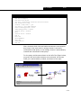
Please note that the above function requires a Component ID for
the components used in the fluid package. This can be found at
2-36
Automation
2-37
in the component view as shown below:
Figure 2.6
Also note that this function can only be used with HYSYS
components, since Aspen Properties pure comonents have
different Component IDs.
2-37
2-38
Key HYSYS Objects
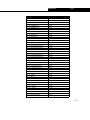
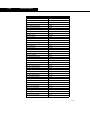
Property Keys Index
The following is the list of property keys for commonly used
properties:
Figure 2.7Property Name
Acidity
Figure 2.8Property Key
11000
Aniline Point
11001
Assay - Aromatics Vol Pct
11002
Assay - Aromatics Wt Pct
11003
Asphaltene Content
11004
Basic Nitrogen Content
11005
C to H Ratio
11006
Cloud Point
11007
Conradson Carbon Content
11008
Copper Content
11009
Cetane Number
11010
Flash Point
11011
Freeze Point
11012
MON (Clear)
11013
MON (Leaded)
11014
Assay - Naphthenes Vol Pct
11015
Assay - Naphthenes Wt Pct
11016
Nickel Content
11017
Nitrogen Content
11018
Assay - Olefins Vol Pct
11019
Assay - Olefins Wt Pct
11020
Assay - Paraffins Vol Pct
11021
Assay - Paraffins Wt Pct
11022
Pour Point
11023
Refractive Index
11024
Reid Vapour Pressure
11025
RON (Clear)
11026
RON (Leaded)
11027
Smoke Point
11028
Sulfur Content
11029
Mercaptan Sulfur Content
11030
Sodium Content
11031
True Vapour Pressure
11032
Vanadium Content
11033
Iron Content
11034
Luminometer Number
11035
C5 Mass
11036
C5 Vol
11037
2-38
Automation
Figure 2.7Property Name
2-39
Figure 2.8Property Key
Viscosity @ 38C
11038
Viscosity @ 50C
11039
Viscosity @ 60C
11040
Wax Content
11041
Pi C6 22DMB Wt Pct
11042
Pi C6 22DMB Vol Pct
11043
Pi C6 23DMB Wt Pct
11044
Pi C6 23DMB Vol Pct
11045
Pi C6 2MP Wt Pct
11046
Pi C6 2MP Vol Pct
11047
Pi C6 3MP Wt Pct
11048
Pi C6 3MP Vol Pct
11049
Pi C7 22-mPentane Wt Pct
11050
Pi C7 22-mPentane Vol Pct
11051
Pi C7 24-mPentane Wt Pct
11052
Pi C7 24-mPentane Vol Pct
11053
Pi C7 223-mButane Wt Pct
11054
Pi C7 223-mButane Vol Pct
11055
Pi C7 33-mPentane Wt Pct
11056
Pi C7 33-mPentane Vol Pct
11057
Pi C7 23-mPentane Wt Pct
11058
Pi C7 23-mPentane Vol Pct
11059
Pi C7 2-mHexane Wt Pct
11060
Pi C7 2-mHexane Vol Pct
11061
Pi C7 3-mHexane Wt Pct
11062
Pi C7 3-mHexane Vol Pct
11063
Pi C7 3-ePentane Wt Pct
11064
Pi C7 3-ePentane Vol Pct
11065
Pi C6 Wt Pct
11066
Pi C6 Vol Pct
11067
Pi C7 Wt Pct
11068
Pi C7 Vol Pct
11069
Pi C8 Wt Pct
11070
Pi C8 Vol Pct
11071
Pi C9 Wt Pct
11072
Pi C9 Vol Pct
11073
Pi C10 Wt Pct
11074
Pi C10 Vol Pct
11075
Pi C11 Wt Pct
11076
Pi C11 Vol Pct
11077
Pn C6 Hexane Wt Pct
11078
Pn C6 Hexane Vol Pct
11079
Pn C7 Heptane Wt Pct
11080
2-39
2-40
Key HYSYS Objects
Figure 2.7Property Name
Pn C7 Heptane Vol Pct
Figure 2.8Property Key
11081
Pn C8 Octane Wt Pct
11082
Pn C8 Octane Vol Pct
11083
Pn C9 Nonane Wt Pct
11084
Pn C9 Nonane Vol Pct
11085
Pn C10 Decane Wt Pct
11086
Pn C10 Decane Vol Pct
11087
Pn C11 n-C11 Wt Pct
11088
Pn C11 n-C11 Vol Pct
11089
On C6 Wt Pct
11090
On C6 Vol Pct
11091
On C7 Wt Pct
11092
On C7 Vol Pct
11093
On C8 Wt Pct
11094
On C8 Vol Pct
11095
On C9 Wt Pct
11096
On C9 Vol Pct
11097
On C10 Wt Pct
11098
On C10 Vol Pct
11099
On C11 Wt Pct
11100
On C11 Vol Pct
11101
A C6 Benzene Wt Pct
11102
A C6 Benzene Vol Pct
11103
A C7 Toluene Wt Pct
11104
A C7 Toluene Vol Pct
11105
A C8 m-Xylene Wt Pct
11106
A C8 m-Xylene Vol Pct
11107
A C8 o-Xylene Wt Pct
11108
A C8 o-Xylene Vol Pct
11109
A C8 p-Xylene Wt Pct
11110
A C8 p-Xylene Vol Pct
11111
A C8 EthBenz Wt Pct
11112
A C8 EthBenz Vol Pct
11113
N C6 cyc-C5 Wt Pct
11114
N C6 cyc-C5 Vol Pct
11115
N C6 cyc-C6 Wt Pct
11116
N C6 cyc-C6 Vol Pct
11117
N C7 cyc-C5 Wt Pct
11118
N C7 cyc-C5 Vol Pct
11119
N C7 cyc-C6 Wt Pct
11120
N C7 cyc-C6 Vol Pct
11121
N C8 cyc-C5 Wt Pct
11122
N C8 cyc-C5 Vol Pct
11123
2-40
Automation
Figure 2.7Property Name
2-41
Figure 2.8Property Key
N C8 cyc-C6 Wt Pct
11124
N C8 cyc-C6 Vol Pct
11125
N C9 cyc-C5 Wt Pct
11126
N C9 cyc-C5 Vol Pct
11127
N C9 cyc-C6 Wt Pct
11128
N C9 cyc-C6 Vol Pct
11129
N C10 cyc-C5 Wt Pct
11130
N C10 cyc-C5 Vol Pct
11131
N C10 cyc-C6 Wt Pct
11132
N C10 cyc-C6 Vol Pct
11133
N C11 cyc-C5 Wt Pct
11134
N C11 cyc-C5 Vol Pct
11135
N C11 cyc-C6 Wt Pct
11136
N C11 cyc-C6 Vol Pct
11137
A C8 Wt Pct
11138
A C8 Vol Pct
11139
A C9 Wt Pct
11140
A C9 Vol Pct
11141
A C10 Wt Pct
11142
A C10 Vol Pct
11143
A C11 Wt Pct
11144
A C11 Vol Pct
11145
N C6 Wt Pct
11146
N C6 Vol Pct
11147
N C7 Wt Pct
11148
N C7 Vol Pct
11149
N C8 Wt Pct
11150
N C8 Vol Pct
11151
N C9 Wt Pct
11152
N C9 Vol Pct
11153
N C10 Wt Pct
11154
N C10 Vol Pct
11155
N C11 Wt Pct
11156
N C11 Vol Pct
11157
Pi Wt Pct
11158
Pi Vol Pct
11159
ON Wt Pct
11160
ON Vol Pct
11161
NP Wt Pct
11162
NP Vol Pct
11163
Oi Wt Pct
11164
Oi Vol Pct
11165
On Wt Pct (normal)
11166
2-41
2-42
Key HYSYS Objects
Figure 2.7Property Name
On Vol Pct (normal)
Figure 2.8Property Key
11167
Pn Wt Pct
11168
Pn Vol Pct
11169
Oi C6 Wt Pct
11170
Oi C6 Vol Pct
11171
Oi C7 Wt Pct
11172
Oi C7 Vol Pct
11173
Oi C8 Wt Pct
11174
Oi C8 Vol Pct
11175
Oi C9 Wt Pct
11176
Oi C9 Vol Pct
11177
Oi C10 Wt Pct
11178
Oi C10 Vol Pct
11179
Oi C11 Wt Pct
11180
Oi C11 Vol Pct
11181
Pn C12+ Wt Pct
11182
Pn C12+ Vol Pct
11183
Pi C12+ Wt Pct
11184
Pi C12+ Vol Pct
11185
Oi C12+ Wt Pct
11186
Oi C12+ Vol Pct
11187
On C12+ Wt Pct
11188
On C12+ Vol Pct
11189
N C12+ Wt Pct
11190
N C12+ Vol Pct
11191
A C12+ Wt Pct
11192
A C12+ Vol Pct
11193
A Wt Pct
11194
A Vol Pct
11195
Centroid Boiling Temperature
11196
Viscosity @ 100C
11197
Liquid Density
2006
Molecular Weight
2004
Fluid Object
A Fluid object is derived from a single ProcessStream through
the DuplicateFluid method. A Fluid object is essentially an
internal copy of the ProcessStream that can be manipulated for
property calculation purposes. The ProcessStream and Fluid
share many of the same properties. A Fluid however can be
2-42
Automation
2-43
flashed without interfering with the simulation case.
Syntax for creating a fluid
SimulationCase.Flowsheet.MaterialStreams(“streamname”).DuplicateFluid
The example below, shows how to create a Fluid off of a stream
and use the Fluid to perform a flash calculation. The
DuplicateFluid method returns a Fluid object. A variety of flashes
could have been performed, but in this case a pressure-vapour
fraction flash is run with the desired pressure and vapour
fraction used as arguments to the method.
Example: Fluid
Public Sub FluidExample(pressureval As Double)
Dim hyFluid As Fluid
Dim hyStream As ProcessStream
Set hyStream = hyCase.Flowsheet.MaterialStreams.Item(0)
Set hyFluid = hyStream.DuplicateFluid
hyFluid.PVFlash pressureval, 0
MsgBox “Bubble Point Temperature = “ & hyFluid.TemperatureValue
End Sub
FluidPhase(s)
The FluidPhases collection object is derived from the Fluid
object. Each FluidPhase in the collection contains a set of
properties and methods that are similar to the Fluid itself except
that the properties correspond to a specific phase of the Fluid.
PhaseTypes (constants):
•
•
•
•
ptUnknownPhase
ptCombinedLiquidPhase
ptCombinedPhase
ptLiquid2Phase
•
•
•
•
ptLiquidPhase
ptPolymerPhase
ptSolidPhase
ptVapourPhase
The PhaseType property of the FluidPhase objects can be
2-43
2-44
Key HYSYS Objects
accessed to determine the type of phase.
Syntax: FluidPhase(s)
Through Collection
Set hyFluidPhase = hyFluid.FluidPhases.Item(0)
HeavyLiquidPhase
Set hyFluidPhase = hyFluid.HeavyLiquidPhase
LightLiquidPhase
Set hyFluidPhase = hyFluid.LightLiquidPhase
VapourPhase
Set hyFluidPhase = hyFluid.VapourPhase
The example below, enumerates through the FluidPhases of a
Fluid and displays the phase type for each fluid in a property
view.
Example: FluidPhase
Dim i As Integer
Dim hyCase As SimulationCase
Dim hyfluid As Fluid
Dim hystream As ProcessStream
Dim hyPhase As FluidPhase
Dim hyPhases As FluidPhases
Set hystream = hyCase.Flowsheet.MaterialStreams.Item(0)
Set hyfluid = hystream.DuplicateFluid
Set hyPhases = hyfluid.FluidPhases
i = 1
For Each hyPhase In hyPhases
If hyPhase.PhaseType = ptVapourPhase Then
MsgBox “Phase “ & i & “ is the vapour phase”
i = i + 1
End If
Next
2.4.6 Operation Objects
A majority of the unit operations in HYSYS are accessible as
Automation objects. Operations can be accessed through the
flowsheet object. Each operation typically has a characteristic
set of properties and methods.
2-44
Automation
2-45
Operations
All operations have a few properties and methods in common.
Operation objects contain properties for determining the feeds,
products, and additional objects connected to the operation. The
operation objects also contain methods for adding and removing
the operations from the flowsheet and the HYSYS case.
Syntax for accessing operations
Getting all the operations on the flowsheet
SimulationCase.Flowsheet.Operations
Getting a specific collection of operations
SimulationCase.Flowsheet.Operations(“PumpOp”)
Getting to a specific operation by name
SimulationCase.Flowsheet.Operations.Item(“UnitName”)
Determining the type of operation
SimulationCase.Flowsheet.Operations.Item(0).TaggedName
The Operations collection object obtained from the flowsheet
returns a collection of all the operations on that flowsheet. It is
possible to filter the collection of operations returned by
specifying the operation type. It is important to note however
that the operations object always returns a collection and not an
individual operation. The objects in the collection need to be
checked in order to find a specific type of operation.
The example below, enumerates through all the operations on
the flowsheet and displays the unit type in a property view.
Example: Operation
Dim i As Integer
Dim hyOperations As Operations
Set hyOperations = hyCase.Flowsheet.Operations
For i = 0 To hyOperations.Count - 1
MsgBox “Operation “ & hyOperations.Item(i).name & “
is unit type - & hyOperations.Item(i).TypeName
Next i
2-45
2-46
Key HYSYS Objects
ColumnOp & ColumnFlowsheet
The column operation is a special kind of operation in HYSYS
and actually contains its own flowsheet. The ColumnFlowsheet is
accessed either from the Columnop object or as a member of
the flowsheets object accessed through the main flowsheet. In
order to access the various temperatures, pressures, and
specifications for a column the ColumnFlowsheet must be
accessed.
Syntax: Accessing Columns
Set objColumn = SimulationCase.Flowsheet.Operations(“ColumnOp”).Item(0)
Set objColumnSubFlow = objColumn.ColumnFlowsheet
The ColumnFlowsheet object contains a considerable amount of
information regarding the column. A variant is used to receive
an array of column pressure information and displays a stage by
stage breakdown of the pressure values.
Example: Column Operation
Dim hyColumn As ColumnOp
Dim hyColumnSubFlowsheet As ColumnFlowsheet
Dim Pressure_Profile As Variant
Set hyColumn = hyCase.Flowsheet.Operations(“ColumnOp”).Item(0)
Set hyColumnSubFlowsheet = hyColumn.ColumnFlowsheet
Pressure_Profile = hyColumnSubFlowsheet.Pressures
For i = 0 To UBound(Pressure_Profile)
MsgBox “Stage “ & i + 1 & “ pressure = “ & Pressure_Profile(i)
Next i
ColumnSpecification(s)
A column is solved based on matching specifications related to
the available degrees of freedom. The ColumnSpecifications
collection object is accessed through the ColumnFlowsheet. The
ColumnSpecification contains information such as the goal
2-46
Automation
2-47
value, current value, and status.
Syntax: ColumnSpecification
Set hyColumn = hyCase.Flowsheet.Operations(“ColumnOp”).Item(0)
Set hyColumnFlowsheet = hyColumn.ColumnFlowsheet
By Index:
Set hyColumnSpec = hyColumnFlowsheet. Specifications.Item(0)
By name:
Set hyColumnSpec = hyColumnFlowsheet.Specifications.Item(“specname”)
The example below, enumerates through all the column
specifications and displays in a property view whether the
specification is active or an estimate.
Example: ColumnSpecification
Dim hyColumnSpec As ColumnSpecification
Dim hyColumnSpecs As ColumnSpecifications
Dim hyColumn As ColumnOp
Dim hyColumnFlowsheet As ColumnFlowsheet
Set hyColumn = hyCase.Flowsheet.Operations(“ColumnOp”).Item(1)
Set hyColumnFlowsheet = hyColumn.ColumnFlowsheet
Set hyColumnSpecs = hyColumnFlowsheet.Specifications
For Each hyColumnSpec In hyColumnSpecs
If hyColumnSpec.IsActive Then
MsgBox “Column spec '" & hyColumnSpec & “' is active.”
Else
MsgBox “Column spec '" & hyColumnSpec & “' is an estimate.”
End If
Next hyColumnSpec
ColumnStage(s) & SeparationStage
The ColumnStages object is a collection of ColumnStage objects
accessed through ColumnFlowsheet. SeparationStage is an
object of ColumnStage and provides a variety of properties
2-47
2-48
Key HYSYS Objects
related to the fluids residing on a particular column stage.
Syntax: ColumnStage(s)
By Index:
Set hyColumnStage = hyColumnFlowsheet.ColumnStages.Item(0)
By Name:
Set hyColumnStage = hyColumnFlowsheet.ColumnStages.Item(“1_Main TS”)
Syntax: SeparationStage
Set hySepStage = hyColumnStage.SeparationStage
The example below, loops through each feed stage and displays
in the Debug property view its molar liquid flows.
Example: ColumnStage
Dim hyColumn As ColumnOp
Dim hyColumnFlowsheet As ColumnFlowsheet
Dim hyFeedStage As Object
Dim hySepStage As SeparationStage
Set hyColumn = hyCase.Flowsheet.Operations(“ColumnOp”).Item(0)
With hyColumn.ColumnFlowsheet
For Each hyFeedStage In .FeedStages
Debug.Print “Stage “ &.ColumnStages(hyFeedStage.name)
StageNumberValue & “ Molar Liquid Flow (kgmole/hr) is “
&.ColumnStages(hyFeedStage.name).
SeparationStage.MolarLiquidFlowValue
Next hyFeedStage
End With
2.4.7 Support Objects
Support objects are used primarily to perform a function or
service to an object in HYSYS. Support objects may not have a
visible equivalent in a HYSYS case when viewed within the
simulation environment. The support objects can be accessed by
several of the objects in HYSYS. The two most commonly
accessed objects in this category are FixedAttachments and
RealVariable.
2-48
Automation
2-49
RealVariable/RealFlexVariable
The RealVariable object provides additional information about a
particular variable such as its units and whether it is calculated
or set. HYSYS performs all calculations in SI units regardless of
how the user preference settings are set. By default, the values
returned through Automation are also in SI units. It becomes
your responsibility to handle how units are handled when writing
applications.
A RealVariable contains a property called GetValue and SetValue
which allows one to specify the units that are to be used when
returning or setting the value.
Syntax for using RealVariable
SimulationCase.Flowsheet.MaterialStreams.Item(0).property
RealVariable Properties/Methods
GetValue
Gets the value in a specified unit.
SetValue
Sets the value in a specified unit.
Status
Returns calculated or specified
Value
Value in SI units.
The RealVariable object also contains a property called Value.
The Value property returns the actual value in SI units within
the HYSYS case. Many of the objects that return a RealVariable
for a given property also have a similarly named property with
the word value concatenated to it. The alternative property
allows direct access to the actual variable in SI units with one
less function call. An example for the ProcessStream object
would be the Temperature property that returns a RealVariable
and the TemperatureValue property, that returns a value in °C.
The RealFlexVariable contains roughly the same properties and
methods as the RealVariable but is used for array values
2-49
2-50
Key HYSYS Objects
returned to variants.
The presence of Flex in the object name indicates the
possibility of a dynamic array (in other words, has a
variable size, depending on what is being returned.)
The example below, shows how to get a stream property value
in a specific unit using the RealVariable method GetValue.
Example 1: RealVariable
Dim hyStream As ProcessStream
Dim TemperatureVal As Double
Set hyStream = hyCase.Flowsheet.MaterialStreams.Item(0)
TemperatureVal = hyStream.Temperature.GetValue(“F”)
MsgBox hyStream.name & “ temperature(F) = “ & TemperatureVal
The example below, shows how to set a stream property value
in a specific unit using the RealVariable method SetValue.
Example 2: RealVariable
Dim hyStream As ProcessStream
Dim TemperatureVal As Double
Set hyStream = hyCase.Flowsheet.MaterialStreams.Item(0)
TemperatureVal = 150
hyStream.Temperature.SetValue 150, “F”
The example below, checks how the temperature value of a
stream is determined by examining the state property.
Example 3: RealVariable
Dim hystream As ProcessStream
Set hystream = hyCase.Flowsheet.MaterialStreams.Item(0)
Select Case hystream.Temperature.State
Case vsCalculated
MsgBox “Temperature value is calculated.”
Case vsSpecified
MsgBox “Temperature value is specified.”
Case vsDefaultedValue
MsgBox “Temperature value is default.”
End Select
The constants vsCalculated, vsSpecified, and
2-50
Automation
2-51
vsDefaultedValue are integer variables specified in the type
library.
Fixed Attachments
The FixedAttachments object is a collection object accessed
from Operations or Stream objects. The FixedAttachments
collection object contains a set of objects related to the feeds,
products, or connected operations.
Syntax: Using FixedAttachments
Set FixAtch = SimulationCase.Flowsheet.Operations.Item(0).AttachedFeeds
Set hyStream = FixAttachObj.Item(0)
Types of objects a FixedAttachments Collection
AttachedFeeds
- ProcessStream
AttachedProducts
- ProcessStream
AttachedLogicalOps
- UnitOperation
AttachedOpers
- UnitOperation
The example below, shows how to determine the streams
attached to a specific unit operation. This example selects the
first column in the operations collection object and then sets an
object to the attached feeds of the column. The names of the
feed streams to the column appear in a property view.
Examples: FixedAttachments
Dim hyFeeds As FixedAttachments
Dim hyOp As ColumnOp
Set hyOp = hyCase.Flowsheet.Operations(“ColumnOp”).Item(0)
Set hyFeeds = hyOp.AttachedFeeds
For j = 0 To hyFeeds.Count - 1
MsgBox “FeedStream “ & j & “ Name = “ & hyFeeds.Item(j).name
Next j
2-51
2-52
Key HYSYS Objects
Solver & Integrator
The Solver is accessed from the SimulationCase object. The
Solver object can be used to turn the calculations on and off.
Syntax for the Solver and Integrator
Solver
SimulationCase.Solver.CanSolve = False
SimulationCase.Solver.CanSolve = True
Integrator
SimulationCase.Solver.Integrator.Active = True
SimulationCase.Solver.Integrator.Active = False
When accessing HYSYS through Automation it is important to
note that HYSYS does not allow communication while it is
solving. If information is sent to HYSYS from a client application,
HYSYS does not return control to the calling program until
calculations are complete. If it is necessary to pass a large
amount of information to HYSYS it is best to turn the solver off
first and then turn it on once the information is sent. Otherwise,
HYSYS calculates after each piece of information is sent and it
takes much longer to transfer the data.
Example: Starting/Stopping the Solver
Dim hystream As ProcessStream
Set hystream = hyCase.Flowsheet.MaterialStreams.Item(0)
hyCase.Solver.CanSolve = False
hystream.Temperature.SetValue 100, “F”
hystream.Pressure.SetValue 1, “atm”
hystream.MassFlow.SetValue 1000, “lb/hr”
hyCase.Solver.CanSolve = True
2-52
Automation
2-53
SpreadsheetOp &
SpreadsheetCell(s)
The SpreadsheetCells object is a collection of SpreadsheetCell
objects. The cell properties allow access to information related
to the HYSYS variable being imported or exported, the formulas
associated with the cell, and the value within the cell.
Syntax: SpreadsheetOp and SpreadsheetCell(s)
Set hySS = hyCase.Flowsheet.Operations.Item(“spreadsheetname”)
Set hyCell = hySS.Cell(columnindex, rowindex)
By utilizing the spreadsheet operation, it is possible to access
nearly every property or value in HYSYS even if the object
associated with that property is not exposed as an Automation
interface.
Example: Accessing Spreadsheet Cells
Dim hySS As SpreadsheetOp
Dim hyCell As SpreadsheetCell
Set hySS = hyCase.Flowsheet.Operations(“spreadsheetop”).Item(0)
Dim x As Variant, y As Variant
For i = 0 To 5
x = 1 ' col #
y = i ' row #
Set hycell = hySS.Cell(x,y)
Debug.Print “CELL VALUE = “ & hyCell.CellValue
Debug.Print “CELL FORMULA = “ & hyCell.CellText
Debug.Print “CELL PROPERTY = “ & hyCell.VariableName & “ (“ &
hyCell.Units & “)”
Next i
2-53
2-54
Key HYSYS Objects
2.4.8 PFD Objects
PFD objects are used for the manipulation and automation of
PFDItems. A PFDItem is any item that is found on the HYSYS
PFD, such as a unit op or a stream. You can use PFD objects to
Move, Size, Mirror, Rotate, Hide, etc. any PFDItem. PFD objects
also allow you to import and display a selection of PFDItems in
to Visio, a CAD application or Excel (what items you get depends
on what parameters you specify). In addition to manipulating
the PFD you can use the PFDConnection object for such things
as finding the “stream line” route between two PFDItems.
Example: Nozzle Type
If nozzle.NozzleType = pfdInletFromMaterialStream Or
nozzle.NozzleType = pfdOutletToMaterialStream Or nozzle.NozzleType =
pfdInletFromStream Or nozzle.NozzleType = pfdOutletToStream Then
newLine.Line.ForeColor.RGB = RGB(0, 0, 128)
newShape.Fill.ForeColor.RGB = RGB(128, 128, 128)
ElseIf nozzle.NozzleType = pfdInletFromEnergyStream Or
nozzle.NozzleType = pfdOutletToEnergyStream Then
newLine.Line.ForeColor.RGB = RGB(128, 0, 0)
newShape.Fill.ForeColor.RGB = RGB(128, 128, 128)
ElseIf nozzle.NozzleType = pfdMaterialStreamInlet Or
nozzle.NozzleType = pfdMaterialStreamOutlet Then
newLine.Line.ForeColor.RGB = RGB(0, 0, 128)
newShape.Fill.ForeColor.RGB = RGB(0, 0, 128)
newShape.Line.ForeColor.RGB = RGB(0, 0, 128)
ElseIf nozzle.NozzleType = pfdEnergyStreamInlet Or nozzle.NozzleType
= pfdEnergyStreamOutlet Then
newLine.Line.ForeColor.RGB = RGB(128, 0, 0)
newShape.Fill.ForeColor.RGB = RGB(128, 0, 0)
newShape.Line.ForeColor.RGB = RGB(128, 0, 0)
Else
newLine.Line.ForeColor.RGB = RGB(0, 255, 0)
End If
2-54
Automation
2-55
2.5 Example 1: The Macro
Language Editor
In this example, you use the HYSYS Macro Language Editor to
build a macro tool that displays the Mach number for a selected
stream over a number of different pipe sizes. The speed of
sound in the stream fluid also appears. The fluid velocity
calculated for each pipe size is the average fluid velocity; no
attempt is made to estimate the maximum velocity.
This complete example has also been pre-built and is located
in the HYSYS\Samples\OLE\macros\mach directory.
1. Begin by opening HYSYS and the Macro Language Editor
which is found under the Tools menu.
Figure 2.9
2-55
2-56
Example 1: The Macro Language
2. Add a function that returns the Stream object that you
choose from a list. Creating separate functions allows for
easy re-use in other programs.
Code
Explanation
Function SelectStream(simcase As Object) As Object
Signifies the beginning of the
SelectStream function. This
function takes a SimulationCase
object and prompts the user to
select a Stream from a list of
streams in the case, returning
an interface to the Stream.
Set FS = simcase.Flowsheet
Acquire the case flowsheet.
Set Strms = FS.MaterialStreams
Acquire the collection of Streams
from the flowsheet.
Dim strmnames()
strmnames = Strms.Names
Build a string array of the
Stream names.
Begin Dialog UserDialog 390,210,”Streams in “ +
Right$(simcase.FullName, Len(simcase.FullName)Len(simcase.Path))
ListBox 20,35,350,119,strmnames(),.listsrc
Text 20,14,360,14,”Select a Stream for Mach
number estimation:”
OKButton 140,175,90,21
CancelButton 270,175,90,21
End Dialog
Generate a user property view
containing a list of Streams
Please notice that the first
button created automatically
becomes the default.
Dim dlg As UserDialog
If Dialog(dlg) = 0 Then End
Finally, run the Dialog and
terminate the macro if the user
cancels (i.e., Dialog function
returns 0).
Set SelectStream = Strms(dlg.listsrc)
Set the function's return value to
the user selected stream
interface.
End Function
Use the Language Help option
provided in the Help menu to
explore the use of UserDialogs.
Signifies the end of the function.
This line does not need to be
added.
The “_” appears at the end of any line of code indicates that
the following line is a continuation of the present line.
2-56
Automation
2-57
3. At this time it is probably a good idea to globally declare
some constants that are used in the Main sub-routine as
shown below.
Figure 2.10
4. You can now begin defining the Main sub-routine. Enter the
following code:
Code
Explanation
Sub Main
Signifies the beginning main
sub-routine.
pipeSizes(1)
pipeSizes(2)
pipeSizes(3)
pipeSizes(4)
pipeSizes(5)
pipeSizes(6)
pipeSizes(7)
pipeSizes(8)
=
=
=
=
=
=
=
=
2
3
4
6
8
10
12
16
Defines an array of pipe
sizes (in inches).
Dim simcase As Object
Set simcase = ActiveCase
If simcase Is Nothing Then
MsgBox “No HYSYS case is open.”
End
End If
Looks for an open active
case. If there is no active
case, it alerts the user and
terminates.
Dim strm As Object
Set strm = SelectStream(simcase)
Calls the SelectStream
function to select a stream
in the simcase.
2-57
2-58
Example 1: The Macro Language
Code
Explanation
Set flow = strm.MassFlow
If flow.IsKnown Then
flowValue = flow.GetValue(“lb/hr”)
flowValue = flowValue / 3600
Else
GoTo NoFlow
End If
Check to see if the selected
stream has a defined mass
flow rate. If the flow rate is
known, convert the flow
rate in to “lb/s”.
Set rho = strm.MassDensity
If rho.IsKnown Then
rhoValue = rho.GetValue(“lb/ft3”)
Else
GoTo NoRho
End If
Checks to see if the
stream’s mass density has
been calculated.
flowValue = flowValue / rhoValue
Calculates volumetric flow
rate.
On Error GoTo NoCv
Cv = strm.MolarHeatCapacityValue / strm.CpCvValue
Proceeds to an error trap if
the Cv value of the stream
has not been calculated.
On Error GoTo NoZ
Z = strm.CompressibilityValue
Proceeds to an error trap if
the compressibility of the
stream has not been
calculated.
On Error GoTo NoTemp
T = strm.TemperatureValue + 273.15
Proceeds to an error trap if
the absolute temperature of
the stream cannot be
calculated.
On Error GoTo NoMolWt
MolWt = strm.MolecularWeightValue / 1000.0
Proceeds to an error trap if
the molecular weight of the
stream cannot be
calculated.
soundVel = Sqr(Z*R*T/MolWt*(1.0+Z*R/Cv))
soundVel = soundVel / 0.3048
soundVelTxt = Format(soundVel, “###,###,###.###”)
Calculates the Speed of
Sound of the stream and
converts it from m/s to ft/s.
Dim DispText() As String
ReDim DispText(nPipes + 2)
DispText(0) = “Pipe Size (in)
Mach
Number
“
DispText(1) = “--------------------------------------------------------------”
Declares an array of String
types. The “+2” leaves
room for a two line header.
The two header lines are
assigned.
Please note there are
eighteen spaces between
“(in)” and “Mach” and four
spaces after “Number”.
There are approximately
seventy dashes in the line
DispText(1) = “---...”
2-58
Automation
Code
2-59
Explanation
For num = 1 To nPipes
rSquared = pipeSizes(num) * pipeSizes(num)/144.0/
4.0
Mach = flowValue / pi / rSquared / soundVel
sizetxt = Format(pipeSizes(num),
"###,###,###.###")
Machtxt = Format(Mach, "###,###,###.#####")
DispText(num + 1) = Format$(sizetxt,
"@@@@@@@@@@@@@@@") + "
" +
Format$(Machtxt, "@@@@@@@@@@@@@@@")
Next num
For each pipe size, the Mach
number is calculated,
formatted and stored in the
previously created array of
strings.
Begin Dialog UserDialog 360,217
ListBox 10,49,340,133,DispText(),.Field5
OKButton 250,189,90,21
Text 30,14,150,14,"Speed of Sound (ft/s):",
.Field2
TextBox 190,14,90,21,.Field1
End Dialog
Dim dlg2 As UserDialog
dlg2.Field1 = soundVelTxt
Dialog dlg2
End
Create a user property view
that displays the Speed of
Sound value as well as the
Mach number for each of
the pipe sizes.
NoFlow:
MsgBox
End
NoRho:
MsgBox
End
NoCv:
MsgBox
strm.name
End
NoZ:
MsgBox
strm.name
End
NoTemp:
MsgBox
strm.name
End
NoMolWt:
MsgBox
strm.name
End
This is where you define the
error trap instances.
End Sub
"Unknown mass flow in stream " + strm.name
Please notice that there are
eighteen spaces between
the quotation marks in the
sixth line of code (ninth line
displayed).
Use the Language Help
option provided in the Help
menu to explore the use of
UserDialogs.
"Unknown density in stream " + strm.name
"Unknown heat capacity in stream " +
"Unknown compressibility in stream " +
"Unknown temperature in stream " +
"Unknown molecular weight in stream " +
Signifies the end of the
method.
2-59
2-60
Example 1: The Macro Language
5. Once you have finished adding this code, you should be
ready to run the program. First ensure that HYSYS has a
case loaded with at least one fully defined stream. You can
start the program using one of the following ways:
•
Start/Resume icon
Right-click on any area of the Macro Language Editor
property view, select Macro | Run command from the
Object Inspect menu.
• Pressing the F5 on the keyboard.
• Clicking the Start/Resume icon on the toolbar.
You should see a property view similar to the one shown
below:
Figure 2.11
6. Select a stream from the list and click the OK button. This
should result in a property view similar to the one shown
below.
Figure 2.12
2-60
Automation
2-61
7. Be sure to save the program by doing one of the following:
•
•
•
Right-click on any area of the Macro Language Editor
property view, select File | Save from the Object
Inspect menu.
Press the CTRL S hot key combination.
Clicking the Save icon in the toolbar.
Save icon
2-61
2-62
Example 2: Automation in Visual
2.6 Example 2:
Automation in Visual
Basic
In this example HYSYS is used as the Automation server for a
unit conversion program. More specifically, you are accessing an
object called the UnitConversionManager which manages unit
conversion within HYSYS.
Although Visual Basic 5.0 is recommended for this example,
you can create this Automation application in Visual Basic
Editor provided in MS Excel 97® and MS Word 97®.
The completed Example 2 has been pre-built and is located in
the HYSYS\Samples\OLE\vb\ ucsm directory.
1. Open a new project in Visual Basic 6.0® and from the New
tab of the New Project property view select the Standard
EXE icon and click the Open button.
Standard EXE icon
2-62
Automation
2-63
Your screen should appear similar to the figure below.
Figure 2.13
Toolbox
Form
Properties Tiled property view
2. By default you should have a form associated with the
project. Begin, by giving the form a name. In the Name field
of the Properties tiled property view give the form the name:
frmUCSM.
3. In the Caption field type: UNIT CONVERSION MANAGER.
This caption should now appear in the Title Bar of the form.
4. Before adding objects to the form, resize the property view
to accommodate the different objects that are required. In
the Width field found in the Properties tiled property view
change the width of the form to 12600 or so that the form is
sufficiently wide enough to contain all the objects you are
adding (see Figure 2.17).
2-63
2-64
Example 2: Automation in Visual
5. From the toolbox select the Combo Box icon and create a
combo box on the form as shown below.
Combo Box icon
Figure 2.14
6. Ensure that the combo box is the active control. This can be
done in one of two ways:
•
Select the combo box on the form so that the object
guides appear around the object.
• From the drop-down list found at the top of the
Properties tiled property view select the name of the
combo box you have just created.
7. In Properties tiled property view, set the name of the Combo
Box as ddUnitSet in the Name field. If you want, you can
also change the default text that appears inside the combo
box by entering a new name in the Text field.
Label icon
8. You can add a Label to the form (i.e., to identify the object
from others), by clicking the Label icon and drawing a label
on the form just above the combo box you have just created.
Figure 2.15
9. Ensuring that the Label control is active using one of the
methods suggested in #6, go to Properties tiled property
view and change the text in the Caption field to Unit
Conversion Set.
2-64
Automation
2-65
10. Now add an Text Box next to the Combo Box you created.
Use the method described in Steps #6 - #7 to name this
Text Box ebFromValue. Repeat Steps #8 - #9 to add a
Label above the ebFromValue Text Box that reads From
Value.
Figure 2.16
11. Add the following objects to the property view using the
previously described methods.
Figure 2.17
Object Type - Label
Object Type - Label
Object Type - Label
Caption - From Unit Conversion
Caption - To Value
Caption - To Unit Conversion
Object Type - Combo Box
Object Type - Label
Object Type - Combo Box
Name - ddFromUnit
Name - lbToValue
Name - ddToUnit
Text - ddFromUnit
Caption - lbToValue
Text - ddToUnit
2-65
2-66
Example 2: Automation in Visual
12. Only two more objects are required on the form. Select the
Command icon control from the toolbox and add two
buttons to the property view as shown below.
Command icon
Figure 2.18
Object Type - Command icon
Object Type - Command icon
Name - btConvert
Name - btExit
Caption - Convert
Caption - Exit
13. You are now ready to begin defining the events behind the
form and objects. You can enter the code environment using
a number of methods:
•
View Code icon
•
•
Click the View Code icon in the Project tiled property
view.
Select the Code command from the View menu.
Double-click the frmUCSM form.
2-66
Automation
2-67
The following property view should appear:
Figure 2.19
The Private Sub Form_Load() method definition is only
visible if you enter the code environment by double-clicking
the form.
14. Begin by declaring the following variables under the Option
Explicit declaration.
Figure 2.20
If you attempt to use an undeclared variable, an error occurs
at compile time.
2-67
2-68
Example 2: Automation in Visual
15. The first sub-routine should already be declared. The
Form_Load sub-routine is the first sub-routine called once
the program is run. It is usually used to initialize the
variables and objects used by the program. Enter the
following code in to the Form_Load sub-routine.
Code
Explanation
Private Sub Form_Load()
Signifies the Start of the form load sub-routine. You do
not have to add it as it should already be there.
ddUnitSet.Clear
ddFromUnit.Clear
ddToUnit.Clear
Clear the default text found inside the ddUnitSet,
ddFromUnit and ddToUnit combo boxes.
Set hyApp = CreateObject("HYSYS.Application")
Set UCSM = hyApp.UnitConversionSetManager
Connects to HYSYS and the HYSYS Unit Conversion Set
Manager.
For Each UCS In UCSM
ddUnitSet.AddItem UCS.Name
Next UCS
For each Unit Conversion Set found in the Unit
Conversion Set Manager add the Unit Set to
ddUnitSet combo box list.
ddUnitSet.ListIndex = -1
Indicates no item is currently selected in the ddUnitSet
combo box.
ebFromValue.Text = ""
lbToValue.Caption = ""
Clears the text that appears in the ebFromValue text
box and the lbToValue label.
End Sub
Signifies the end of the initialization sub-routine. This
line does not need to be added.
16. The next section of code to be added tells the program what
is to occur when an option is selected in the ddUnitSet
combo box.
Code
Explanation
Private Sub ddUnitSet_Click()
Signifies the Start of the sub-routine.
ddFromUnit.Clear
ddToUnit.Clear
Clears any list entries in the ddFromUnit and
ddToUnit combo boxes.
Set hyApp = CreateObject("HYSYS.Application")
Set UCSM = hyApp.UnitConversionSetManager
Connects to HYSYS and the HYSYS Unit Conversion Set
Manager.
UCSNumber = ddUnitSet.ListIndex
Once the selection is made in the ddUnitSet combo
box, the UCSNumber variable holds the internal
HYSYS index number of the selected Unit Set.
Set UCS = UCSM.Item(UCSNumber)
Find the selected Unit Conversion Set in Unit
Conversion Manager.
For Each UC In UCS
ddFromUnit.AddItem UC.Name
ddToUnit.AddItem UC.Name
Next UC
For each Unit Conversion type (UC) in the Unit
Conversion Set, add the Unit type to both the
ddFromUnit combo box (the unit type the program is
converting from) and the ddToUnit (the unit type the
program is converting to).
ddFromUnit.ListIndex = -1
ddToUnit.ListIndex = -1
Indicates no items are currently selected in the
ddFromUnit and ddToUnit combo box.
2-68
Automation
Code
2-69
Explanation
Clears any text that appears in the lbToValue label.
lbToValue.Caption = ""
End Sub
Signifies the end of the sub-routine. This line does not
need to be added.
17. The next 2 sub-routines reset the lbToValue label whenever
an option is selected in either the ddFromUnit or ddToUnit
combo box.
Code
Explanation
Private Sub
ddFromUnit_Click()
Signifies the Start of the sub-routine.
Clears any text that appears in the lbToValue label.
lbToValue.Caption = ""
End Sub
Signifies the end of the sub-routine. This line does not need to
be added.
Code
Explanation
Private Sub ddToUnit_Click()
Signifies the Start of the sub-routine.
Clears any text that appears in the lbToValue label.
lbToValue.Caption = ""
End Sub
Signifies the end of the sub-routine. This line does not need to
be added.
18. The final two sub-routines define the actions of the two
buttons: btConvert and btExit.
Code
Explanation
Private Sub btConvert_Click()
Signifies the Start of the sub-routine.
Set hyApp = CreateObject("HYSYS.Application")
Set UCSM = hyApp.UnitConversionSetManager
Connects to HYSYS and the HYSYS Unit
Conversion Set Manager.
FromValue = CDbl(Val(ebFromValue.Text))
Takes the value entered in the ebFromValue text
box and converts in to a numerical variable type.
ebFromValue.Text = CStr(FromValue)
Set ebFromValue text box text equal to
FromValue double.
UCSNumber = ddUnitSet.ListIndex
FromNumber = ddFromUnit.ListIndex
ToNumber = ddToUnit.ListIndex
Gets current selection in the three drop-down lists
(combo boxes).
If FromNumber < 0 Or ToNumber < 0 Then
lbToValue.Caption = ""
Exit Sub
End If
If no selection is made in either the ddFromUnit
or ddToUnit combo boxes, exit the sub-routine.
Set UCS = UCSM.Item(UCSNumber)
Set FromUC = UCS.Item(FromNumber)
Set ToUC = UCS.Item(ToNumber)
Chooses a specific UCS from UCSM. It takes the
Unit conversion type you want to change from,
and the Unit Conversion type you want to change
to.
2-69
2-70
Example 2: Automation in Visual
Code
Explanation
Intermediate = FromUC.ToCalculationUnit(FromValue)
ToValue = ToUC.FromCalculationUnit(Intermediate)
lbToValue.Caption = CStr(ToValue)
Converts the contents of the ddFromValue
combo box from the FromUC units to HYSYS
internal units (Intermediate). It then converts
the Intermediate value from internal units to the
ToUC units. It then displays the converted value
in the lbToValue label.
End Sub
Signifies the end of the sub-routine. This line does
not need to be added.
Code
Explanation
Private Sub btExit_Click()
Signifies the Start of the sub-routine.
Unloads the form and ends the program.
Unload Me
End
End Sub
Signifies the end of the sub-routine. This line does
not need to be added.
19. You are now ready to compile and run the program. Before
you begin, please ensure that you have a copy of HYSYS on
the computer.
20. To compile the program do one of the following:
Start icon
•
•
•
VB
Click the Start icon in the toolbar.
Select Start command from the Run menu.
Press F5 from the keyboard.
informs you of any errors that occur during compile time.
2-70
Extensibility
3-1
3 Extensibility
3.1 Introduction................................................................................... 3
3.2 Implementing Interfaces ............................................................... 5
3.2.1 Implementing an Interface Through a Dispatch Interface............... 5
3.2.2 Implementing an Interface Through a Custom Interface ................ 6
3.3 Data Types ..................................................................................... 6
3.4 Extension Development Kit ............................................................ 7
3.5 Creating an Extension .................................................................... 9
3.5.1 In Visual Basic ......................................................................... 9
3.5.2 In C++ ................................................................................. 13
3.5.3 In C# or VB.NET .................................................................... 17
3.6 Registering Extensions ................................................................ 21
3.6.1 Registering Extensions Written in C++ ...................................... 22
3.6.2 Registering Extensions Written in Visual Basic ............................ 24
3.6.3 Registering Extensions Written in C# or VB.NET ......................... 25
3.7 Extension Interface Details.......................................................... 26
3.7.1 ExtnContainer Interface .......................................................... 26
3.7.2 ExtensionObject Interface ....................................................... 28
3.8 Extension Reaction Kinetics ......................................................... 28
3.8.1 ExtnKineticReaction Interface................................................... 30
3.8.2 ExtnKineticReactionContainer Interface ..................................... 31
3.8.3 Kinetic Reaction Example ........................................................ 31
3.9 Extension Property Packages ....................................................... 46
3.9.1 ExtnPPkgContainer Interface.................................................... 50
3-1
3-2
Extensibility
3.9.2 ExtnPropertyPackage Interface .................................................51
3.10 Extension Unit Operations ..........................................................52
3.10.1 ExtnUnitOperationContainer Interface....................................53
3.10.2 ExtnUnitOperation Interface .................................................54
3.10.3 Passes...............................................................................54
3.11 Extension Transition Objects ......................................................80
3.11.1 Source Code.........................................................................80
Overview ......................................................................................81
Global Variables .............................................................................81
Initialize........................................................................................81
Edf...............................................................................................86
3.11.2 Example ..............................................................................87
Overview ......................................................................................87
Installing the Extension...................................................................88
Installing Aspen HYSYS Oil ..............................................................88
Installing REFSYS Oil ......................................................................89
Building the Flowsheet ....................................................................90
3.12 References..................................................................................90
3-2
Extensibility
3-3
3.1 Introduction
HYSYS provides the unique capability of enhancing its
functionality through the addition of custom objects to a
simulation. With its open concept, the functionality of HYSYS
can be extended to include your unique or proprietary
calculations. Currently, you can add:
•
•
•
Extension Unit Operations
Extension Reaction Kinetics
Extension Property Packages
Extensions are packaged in to two distinct files making them
easy to transfer to different machines. The extension code
becomes part of a DLL (dynamic linked library), that hides its
proprietary information, making it an excellent vehicle for
commercial distribution. Extensions become part of the
simulation and participate in simulation calculations like any
other HYSYS object. For example, each extension unit operation
has a corresponding PFD icon and property view. Also, the
Extension has its Execute method called by the Steady-State
Solver. Unlike applications which interact with HYSYS through
Automation, extensions exist in process with the HYSYS
applications. New extensions can be written in any language
that supports Automation (formerly OLE Automation). This
provides much flexibility to the end user, who can develop the
extension in languages such as C++ or Visual Basic. By its very
nature, Visual Basic provides the easiest development
environment in which to create unit operation and kinetic
reaction extensions. The Extension Property Package interface
must be implemented as a custom interface, therefore C++
must be used.
Each type of extension is represented in HYSYS by an Extension
Container. This object is the gateway through which HYSYS
communicates with the extension. The Container can also
provide a number of services to the extension, such as
performing Mass Balances or allowing access to the Status Bar.
3-3
3-4
Introduction
Figure 3.1
HYSYS
Container
Extension
Code
HYSYS finds extensions by looking for specific keys in the
System Registry. When an extension is registered on a
computer, information about it is added to the Registry. Upon
start-up, HYSYS scans the Registry for this information, and
adds user-specified descriptions to the appropriate lists within
the program. For instance, when a unit operation extension is
created with the description provided as “MY Unit Op”. This text
appears in the HYSYS UnitOps property view in the Available
Unit Operations pane so that the user can create instances of
them.
When the user asks for an extension to be created, HYSYS
instantiates the object and calls its Initialize method. At this
point, the extension code gains access to its Container. After the
extension has been initialized, it behaves like any other HYSYS
object of the same class.
All extensions must support at least two interfaces:
•
•
The ExtensionObject interface
At least one other interface particular to the type of
extension
Containers support one interface, which is particular to the type
of container.
3-4
Extensibility
3-5
3.2 Implementing
Interfaces
An extension implements an interface if it supports the methods
in that interface. There are two different ways of implementing
an interface.
3.2.1 Implementing an
Interface Through a
Dispatch Interface
An extension can implement interfaces through Dispatch
interfaces. This can be done in Visual Basic if the extension is
implemented as a Visual Basic Class.
When an extension is implemented in this manner, only the
methods of the interface that are required for minimal operation
of the extension need be used. All other methods may be
ignored, or they can be provided if the extension implements
that functionality.
For example, an extension Unit Operation can be implemented
by supporting only the Initialize and Execute methods. The
BasisChanged method need only be implemented if the
extension needs to be notified when the Basis of the simulation
has changed.
3-5
3-6
Data Types
3.2.2 Implementing an
Interface Through a
Custom Interface
An extension can also be implemented by overloading the
Custom interfaces defined for the extension. For example, an
extension Unit Operation can be created by overloading the
ExtensionObject interface and the ExtnUnitOperation interface.
When an extension is created in this manner, all methods of the
interface must be overloaded (this is a requirement of the C++
language definition). If a method does not contain any
functionality, however, the error condition E_NOTIMPL should be
returned to indicate to HYSYS that the method is not being
used. Using the Extension Unit Operation as an example once
again; each of the methods in its two supported interfaces must
be overloaded, but only the Initialize and Execute methods need
return anything other than E_NOTIMPL.
3.3 Data Types
This documentation for the most part uses Visual Basic syntax in
its sample code and examples. The following table provides a
map of Visual Basic types to C++, .NET, C#, and VB.NET types.
Visual Basic Type
C++ Type
.NET Type
C# Type
VB.NET Type
Variant
VARIANT
System.Object
object
Object
String
BSTR
System.String
string
String
Boolean
VARIANT_BOOL
System.Boolean
bool
Boolean
Long
long
System.Int32
int
Integer
Integer
short
System.Int16
short
Short
Double
double
System.Double
double
Double
Single
float
System.Single
float
Single
arrays
SAFEARRAY
System.Array
Array or specific
(string[], int[],
double[])
Array or specific
(string(), int(),
double())
3-6
Extensibility
3-7
When sending an array of numbers to HYSYS they should
always be of type REAL or LONG.
3.4 Extension
Development Kit
A number of tools are provided in the HYSYS Extension
Development Kit. These tools are not required to build
extensions for HYSYS, but they make the job much easier.
Included in the kit are the following:
File
Description
hysys.tlb
The HYSYS Type Library, that contains definitions for all
objects exposed by HYSYS, as well as definitions for
interfaces required by HYSYS Extensions. Programming
languages such as Visual Basic use this file to determine
what a particular object contains. Many programs
provide browsers to look at the contents of this file. For
example, Excel provides an Object Browser that can be
used to view the properties of methods of each object
and to help navigate the object model. Unlike the other
files in the table, the HYSYS Type Library is always
installed, even when you do not install the Extension
Development Kit.
extsdk.bas
Contains constants defined by HYSYS in a format that
can easily be included in a Visual Basic project. This
allows the extension developer to refer to HYSYS
constants through Const definitions, rather than
through numbers. This information can also be read
from the HYSYS Type Library, if your programming
language supports this.
extsdk.cpp and
extsdk.hpp
Contain support code that can be included in a C++
project. They implement a ClassFactory for any
extensions in the project and also implement the
DllRegisterServer and DllUnregisterServer methods.
These files compile in both Microsoft Visual C++ and
Borland C++.
hysys.hh
Contains definitions of all the interfaces and
enumerations found in the HYSYS Type Library.
Including this file in your C++ source allows you to call
methods on HYSYS interfaces.
hysysiid.cc
Instantiates all of the GUIDs defined by HYSYS. It can
be included as part of a C++ project to allow reference
to HYSYS GUIDs.
3-7
3-8
Extension Development Kit
File
Description
The HYSYS View
Editor
Allows you to:
• Define extension information for the registration
program.
• Define Variables for HYSYS to create and manage
on behalf of an extension.
• Create property views for an extension.
Aspentech.
HYSYS.Interop.
dll
The HYSYS Interop Assembly contains .NET definitions
for all objects exposed by HYSYS as well as definitions
for interfaces required by HYSYS Extensions.
.NET programming languages such as C# or Visual
Basic use this file to determine what a particular object
contains. Visual Studio provides an object browser that
can be used to look at the contents of this file. Like the
HYSYS Type Library, the HYSYS Interop Assembly is
always installed, even when you do not install the
Extension Development Kit.
3-8
Extensibility
3-9
3.5 Creating an Extension
3.5.1 In Visual Basic
Creating an extension in Visual Basic is a very straightforward
procedure. The following six steps can be used as a general
framework:
1. Create the Extension Definition.
2. Create the Object property views.
3. Implement the Required Methods.
4. Register the Extension.
5. Debug the Extension.
6. Distribute the Extension.
These steps are explained in more detail in the following
sections.
Create the Extension Definition
The EDF contains important information about an extension that
is required by the extension's container in HYSYS. Specifically, it
contains information about the variables that the extension own
(that are managed by the container), and it can also contain one
or more property views for the object.
The extension definition file, which contains the definition of
the extension is created using the View Editor.
For each extension, you must provide either a CLSID or a
ProgID. Other information that can be provided at this point
includes: the extension description, from which you identify the
extension within HYSYS, the extension type and the number of
property views. For extensions written in Visual Basic, you must
specify a ProgID. The selection of the ProgID is explained in the
following sub-section entitled: Register the Extension.
3-9
3-10
Creating an Extension
It is possible to create an EDF with 0 views.
For more information on
the View Editor see
Chapter 4 - Extension
View Editor.
Once the preliminary definition information is provided, you
specify the variables that the object owns and that are visible to
the user. These variables are of the following types:
Variable Type
Description
Numeric
• Represent numerical quantities and have a
Variable Type that allows HYSYS to manage Unit
Conversions for the user.
• May have zero, one, or two dimensions.
• Can also trigger the steady state solver when
they are changed. If this is the case, the variable
operates like other HYSYS variables in that the
solver performs consistency checking when
values are changed.
Text
• Represents a string.
• May be zero- or one-dimensional.
Message
Usually associated with buttons in a property view.
Messages are sent through the VariableChanged
method of an extension.
Numeric Variables and Text Variables may or may not be
persistent. If they are, their values are stored when the
Simulation Case containing the extension is saved.
Create the Object Property View(s)
A property view for your extension is not necessary, but quite
often you want the user to be able to interact with your object.
The View Editor can be used to create property views for your
object.
Views are created by adding widgets to the DefaultView form.
Select a widget with the secondary mouse button, drag it on to
the DefaultView form, and drop it. You can then position the
widget to your liking. Double-click the widget to access its
Properties property view, from which you can specify detailed
information for the widget. If necessary, you can associate a
variable with the widget.
A widget is an equivalent term for a Visual Basic control.
3-10
Extensibility
3-11
Each DefaultView form must have a unique name. The object’s
default property view must be called DefaultView as it is the
property view HYSYS attempts to open when the object is
instantiated, provided the functionality of the OnView method is
not overridden.
Implement the Required Methods
To implement an extension from Visual Basic, you must create a
project containing a Class Module. This Class Module must
implement whatever methods are required by the container. For
example, to implement an Extension Unit Operation, you must
implement an Initialize method and an Execute method, and
these methods must have the same parameters as defined by
the interface.
Register the Extension
Before you register your extension, you must ensure that the
ProgID defined by your Visual Basic project is the same as that
which you entered in the EDF for this object. ProgIDs are
defined by Visual Basic in the following form:
ProjectName.ClassName
where:
ProjectName = the name of the project (which is set on the
Project tab of the Options property view in VB 5.0)
ClassName = the name of the class (which is set through the
Name parameter of the class' property view).
For Example, a class called Extension1 in a project called
AspenTechExtensionProject would have a ProgID of
AspenTechExtensionProject.Extension1.
For more information on
extension registration
see Section 3.6 Registering
Extensions.
You can register extensions on the Extensions tab of the Session
Preferences property view.
3-11
3-12
Creating an Extension
Debug the Extension
For more information on
debugging, please
consult your Visual Basic
manual and help files.
To debug the extension, you can set breakpoints on just about
any line in your Visual Basic class. Initially, you should probably
set a breakpoint on the Initialize method. Then, start the
extension (via the Start button or the Start command in the Run
menu).
Next, start HYSYS and create an instance of your extension. This
is done in the same manner as you would create other objects of
the same class. For example, extension Unit Operations can be
created through the UnitOps property view (accessed though
the F12 key).
When you create an instance of your extension, HYSYS creates a
container for it. This container first creates an instance of your
Visual Basic class, and then calls its Initialize method. At this
point, your breakpoint in Visual Basic should be reached. Now
you can inspect variables and step though your code.
You can also use the Debug object in Visual Basic to print
information to the Debug property view while the extension
runs.
Distribute the Extension
Once you are confident that your extension is behaving properly,
you can create an ActiveX DLL file. Create the DLL file by
selecting the appropriate option from Visual Basic’s File menu.
The end result of this step is an extension that you can
distribute without exposing any proprietary information or
methods.
To distribute your extension, you must provide the DLL file, the
EDF file, and any other files required by your extension (i.e., a
separate FORTRAN DLL called from your extension). You must
register your extension on each individual machine that uses the
extension calculations. You can use the registration tool found
on the Extensions tab of the Session Preferences property view
for this, or you can include this step in your own setup program.
3-12
Extensibility
3-13
3.5.2 In C++
The following six steps provide a framework for creating an
extension in C++:
1. Create the Extension Definition.
2. Implement the Required Interfaces.
3. Implement the ClassFactory.
4. Create and Register the DLL.
5. Debug the Extension.
6. Distribute the Extension.
These steps are explained in more detail in the following
sections.
Create the Extension Definition
The EDF contains important information about an extension that
is required by the extension's container in HYSYS. Specifically, it
contains information about the variables that the extension own
(that are managed by the container), and it may also contain
one or more property views for the object.
The extension definition file, which contains the definition of
the extension is created using the View Editor.
For each extension, you must provide either a CLSID or a
ProgID. Other information that can be provided at this point
includes: the extension description, from which you identify the
extension within HYSYS, the extension type and the number of
property views. The selection of the ProgID is explained in the
following sub-section entitled: Register the Extension.
It is possible to create an EDF with 0 views.
3-13
3-14
Creating an Extension
For more information on
the View Editor see
Chapter 4 - Extension
View Editor.
Once the preliminary definition information is provided, you
specify the variables that the object owns and that is visible to
the user. These variables are of the following types:
Variable Type
Description
Numeric
• Represent numerical quantities and have a
Variable Type that allows HYSYS to manage Unit
Conversions for the user.
• May have zero, one, or two dimensions.
• Can also trigger the steady state solver when
they are changed. If this is the case, the variable
operates like other HYSYS variables in that the
solver performs consistency checking when
values are changed.
Text
• Represents a string.
• May be zero- or one-dimensional.
Message
Usually associated with buttons in a property view.
Messages are sent through the VariableChanged
method of an extension.
Numeric Variables and Text Variables may or may not be
persistent. If they are, their values are stored when the
Simulation Case containing the extension is saved.
Implement the Required Interfaces
To create an extension in C++, you must create a class that
implements the required interfaces. For example, an Extension
Unit Operation must implement the ExtensionObject interface
and the ExtensionUnitOperation interface. This calculation can
be done through inheritance or aggregation. HYSYS functions if
either approach is taken, as long as the interfaces are supported
through the COM QueryInterface mechanism.
To implement an extension, you must provide code for the
standard COM IUnknown methods (AddRef, Release,
QueryInterface), as well as any methods required by the
interfaces you are supporting. Other methods may return
E_NOTIMPL if you choose not to implement them.
3-14
Extensibility
3-15
Definitions of the interfaces that you must implement (as well as
any interfaces provided by HYSYS objects) are provided in the
hysys.hh file, that is included in the Extension Development Kit.
You must include this file in any source files that access the
defined interfaces.
Implement the Class Factory
When HYSYS creates an instance of your extension object, it
accesses the COM Library which calls the function
DllGetClassObject which is contained in the DLL. DllGetObject
creates the requested class factory. You can implement a
ClassFactory yourself, or you can use the one provided in
extsdk.cpp (which is included in the Extension Development
Kit).
If you choose to use the ClassFactory provided by extsdk.cpp,
you must implement the REGISTER_EXTENSION macro
somewhere in your code. This macro provides information to the
ClassFactory on how to create an instance of your extension.
The syntax of this macro is:
REGISTER_EXTENSION(ClassName, clsid, VisibleDescription)
where:
ClassName = the C++ name of the class
clsid = the CLSID of the class
VisibleDescription = a string containing a description of the
class that a user can understand
You must implement this macro once for every extension in your
DLL.
3-15
3-16
Creating an Extension
Create & Register the DLL
When you build your project, you must implement it as a 32-bit
Dynamic Link Library (DLL). This DLL must contain code for your
extension, a ClassFactory to create your extensions, and a
DllRegisterServer entry point.
The Extension Development Kit provides extsdk.cpp, which
contains a ClassFactory and an implementation of
DllRegisterServer. If you use this ClassFactory, you must include
this file in your project.
For more information on
extension registration
see Section 3.6 Registering
Extensions.
You can register your DLL on the Extensions tab of the Session
Preferences property view.
Debug the Extension
You can debug your extension by putting a call to the Win32
function DebugBreak in your code. When HYSYS executes this
part of your code, you are allowed to start your debugger and
debug the code from there. You are then able to inspect
variables, and trace the execution of your extension's code. You
can also debug your extension in MS DevStudio by setting
breakpoints in the code. Specifying the path of the HYSYS
executable file in the Executable for debug session field on the
Debug tab of the Project Settings property view and launch
VC++ auto debug.
You can load your extension by starting HYSYS and creating an
instance of the extension. HYSYS creates a container, and this
container then calls the extension's Initialize method.
Distribute the Extension
Once you are confident that your extension is behaving properly,
you can create an ActiveX DLL file. The end result of this step is
an extension that you can distribute without exposing any
proprietary information or methods.
3-16
Extensibility
3-17
To distribute your extension, you must provide the DLL file, the
EDF file, and any other files required by your extension (i.e., a
separate FORTRAN DLL called from you extension). You must
register your extension on each individual machine that uses the
extension calculations. You can use the registration tool found
on the Extensions tab of the Session Preferences property view
for this, or you can include this step in your own setup program.
3.5.3 In C# or VB.NET
Creating an extension in Visual Basic is a very straightforward
procedure. The following six steps can be used as a general
framework:
1. Create the Extension Definition.
2. Create the Object property views.
3. Implement the Required Methods.
4. Register the Extension.
5. Debug the Extension.
6. Distribute the Extension.
These steps are explained in more detail in the following
sections.
Create the Extension Definition
The EDF contains important information about an extension that
is required by the extension's container in HYSYS. Specifically, it
contains information about the variables that the extension own
(that are managed by the container), and it may also contain
one or more property views for the object.
The extension definition file, which contains the definition of
the extension is created using the View Editor.
For each extension, you must provide either a CLSID or a
ProgID. Other information that can be provided at this point
includes: the extension description, from which you identify the
extension within HYSYS, the extension type and the number of
3-17
3-18
Creating an Extension
property views. The selection of the ProgID is explained in the
following sub-section entitled: Register the Extension.
It is possible to create an EDF with 0 views.
Once the preliminary definition information is provided, you
specify the variables that the object owns and that are visible to
the user. These variables are of the following types:
Variable Type
Description
Numeric
• Represent numerical quantities and have a
Variable Type that allows HYSYS to manage Unit
Conversions for the user.
• May have zero, one, or two dimensions.
• Can also trigger the steady state solver when
they are changed. If this is the case, the variable
operates like other HYSYS variables in that the
solver performs consistency checking when
values are changed.
Text
• Represents a string.
• May be zero- or one-dimensional.
Message
Usually associated with buttons in a property view.
Messages are sent through the VariableChanged
method of an extension.
Numeric Variables and Text Variables may or may not be
persistent. If they are, their values are stored when the
Simulation Case containing the extension is saved.
Create the Object Property View(s)
A property view for your extension is not necessary, but quite
often you want the user to be able to interact with your object.
The View Editor can be used to create property views for your
object.
Views are created by adding widgets to the DefaultView form.
Select a widget with the secondary mouse button, drag it onto
the DefaultView form, and drop it. You can then position the
widget to your liking. Double-click the widget to access its
Properties property view, from which you can specify detailed
information for the widget. If necessary, you can associate a
3-18
Extensibility
3-19
variable with the widget.
A widget is an equivalent term for a control.
Each DefaultView form must have a unique name. The object’s
default property view must be called DefaultView as it is the
property view HYSYS attempts to open when the object is
instantiated, provided the functionality of the OnView method is
not overridden.
Implement the Required Methods
To implement an extension in C# or VB.NET, you must first
create a Class Library project. In the project, you must then add
a reference to the HYSYS Interoperability Library
(Aspentech.HYSYS.Interop.dll) which can be found in the root
directory of the install location for Aspen HYSYS.
Next, you must create a class that implements the required
interfaces. For example, an Extension Unit Operation must
implement the ExtensionObject interface and the
ExtensionUnitOperation interface.
The class should have the appropriate attributes from the
System.Runtime.InteropServices namespace required to
export a class to COM. These include but are not limited to
ComVisible, ClassInterface, GuidAttribute, and
ProgIdAttribute. ComVisible must be set to true;
ClassInterface is recommend to be set to AutoDispatch which
is the default; GuidAttribute represents the CLSID and will be
generated if not specified (its highly recommended that you
specify this manually); ProgIdAttribute is optional unless you
refer to this class using the ProgID in the Extension Definition.
For more information on
extension registration
see Section 3.6 Registering
Extensions.
Register the Extension
You can register extensions on the Extensions tab of the Session
Preferences property view or using the regextn.exe commandline executable.
3-19
3-20
Creating an Extension
Debug the Extension
To debug the extension, you can set breakpoints on just about
any line in your class. Initially, you should probably set a
breakpoint on the Initialize method. Then, set HYSYS.exe as the
external program in the Project Properties Debug page.
You can debug your extension in Microsoft Visual Studio 2003 or
2005 by setting breakpoints in the code and by attaching to
running copy of HYSYS from the Attach to Process dialog from
the Tool menu. When attaching the extension to a running
HYSYS case, ensure that you select the managed code debug
option and not native code debug option. You can also start
HYSYS from Microsoft Visual Studio by specifying the path of the
HYSYS executable file in the Start external program field on the
Debug tab of the Project Settings property view.
You can load your extension by starting HYSYS and creating an
instance of the extension. HYSYS creates a container, and this
container then calls the Initialize method of that extension. You
can also use the System.Diagnostics.Debug.Print method in
.NET to print information to the Output Debug view while the
extension runs.
Note: Microsoft Visual Studio .NET 2003 cannot debug a
managed process if .NET 2.0 is being used (HYSYS uses .NET
2.0 by default). You can override this behaviour and force .NET
1.1 to be used so that Visual Studio .NET 2003 can debug the
extension by adding a file called hysys.exe.config to same
directory as hysys.exe that states:
<configuration>
<startup>
<requiredRuntime version="v1.1.4322"/>
</startup>
</configuration>
Distribute the Extension
Once you are confident that your extension is behaving properly,
you can create an ActiveX DLL file. The end result of this step is
an extension that you can distribute without exposing any
3-20
Extensibility
3-21
proprietary information or methods.
To distribute your extension, you must provide the DLL file, the
EDF file, and any other files required by your extension (i.e., a
separate FORTRAN DLL called from you extension). You must
register your extension on each individual machine that uses the
extension calculations. You can use the registration tool found
on the Extensions tab of the Session Preferences property view
for this, or you can include this step in your own setup program.
3.6 Registering Extensions
In order for HYSYS to find extensions, they must be registered
in the Extensions tab of the Session Preferences property view.
HYSYS looks for extensions in the:
HKEY_CLASSES_ROOT\Software\AspenTech\HYSYS\1.1\Extension
s key.
Each extension should have the following information under this
key:
KeyName = Descriptive Name of Extension
ExtensionDefinitionFile = name of Extension Definition File
ExtensionType = type, class
CLSID = CLSID of Extension or
ProgID = ProgID of Extension
See Chapter 4 Extension View Editor
for more information on
creating an EDF.
All this information is provided when the EDF is created in the
View Editor.
Extensions can be registered with either a CLSID (Class
Identifier) or a ProgID (Program Identifier). It is recommended
that ProgID be used for extensions created in Visual Basic, and
CLSID be used for all other extensions.
Only one of the ProgID or CLSID values can be used.
The Extension Definition File entry gives the name of the
3-21
3-22
Registering Extensions
Extension Definition File for the object.
The type of the extension is given by the ExtensionType entry.
The type can be UnitOperation, PropertyPackage or
KineticReaction. The class descriptor is optional, and currently is
ignored if present.
3.6.1 Registering Extensions
Written in C++
When you create an extension in C++, you must implement a
DllRegisterServer function in the DLL containing the extension.
This function is called from HYSYS when registering the
extension. The file extsdk.cpp that is included with the
Extension Development Kit provides code that implements this
function.
Ensure that the EDF and extension DLL are in the same
directory.
To register an extension written in C++, simply use the
following procedure:
1. Start HYSYS. From the Tools menu, select Preferences
command. The Session Preferences property view opens.
2. Go to the Extensions tab and click the Register an
Extension button. This opens the Select an Extension to
be Registered property view.
3-22
Extensibility
3-23
3. Use the File Path group to find the directory in which the
DLL file is saved. Once you find the DLL file, select it and
click the OK button.
Figure 3.2
The Extensions tab should now appear similar to the figure
below.
Figure 3.3
You are now ready to use the extension in HYSYS.
3-23
3-24
Registering Extensions
3.6.2 Registering Extensions
Written in Visual Basic
Refer to Section 3.6.1 Registering
Extensions Written in
C++, for the step by
step procedure for
registering HYSYS
extensions.
Extensions written in Visual Basic may be run from within Visual
Basic, or may be compiled to an ActiveX DLL file. Either way,
Visual Basic takes care of registering half of the information
required for HYSYS to find the extension. The HYSYS
registration tool provided in the Session Preferences property
view may be used to register the other half.
Running Within Visual Basic
If you are running your extension within the Visual Basic
environment, Visual Basic temporarily adds information to the
registry every time the project is run. This information changes
every time you run the project. The extra information needed
can be added by going to the Extensions tab of the Session
Preferences property view and registering the EDF file. When
run this way, information about where to find an extension is
added to the registry, but information on how to create it is not.
To view EDF files in Select an Extension to be Registered
property view, you must change the settings in the File Filter
drop-down list from Application Extensions (*.dll) to
Extension Definition Files (*.edf).
Compiled DLL Files
When you compile your extension to an ActiveX DLL file, you
must do both parts of the registration. You can use the
procedure described in the Section 3.6.1 - Registering
Extensions Written in C++ to register the DLL files in the
HYSYS Session Preferences.
HYSYS loads the DLL file and registers it, and then it takes the
name of the DLL file and looks for an Extension Definition File
with the same name in the same directory to complete the
registration.
3-24
Extensibility
3-25
3.6.3 Registering Extensions
Written in C# or VB.NET
To register an extension written in C# or VB.NET, use the
following procedure:
1. Start HYSYS. From the Tools menu, select Preferences
command. The Session Preferences property view opens.
2. Go to the Extensions tab and click the Register an
Extension button. This opens the Select an Extension to
be Registered property view.
3. Use the File Path group to find the directory in which the
DLL file is saved. Once you find the DLL file, select it and
click the OK button.
Figure 3.4
The Extensions tab should now appear similar to the figure
3-25
3-26
Extension Interface Details
below.
Figure 3.5
You are now ready to use the extension in HYSYS.
3.7 Extension Interface
Details
Three types of extensions can currently be created for use
within HYSYS:
•
•
•
Unit Operations
Kinetic Reactions
Property Packages
Each extension type is associated with a unique container
interface derived from the ExtnContainer object. For instance
Unit Operation Extensions have an ExtnUnitOperation interface.
3.7.1 ExtnContainer Interface
Each type of extension has a unique container associated with it.
Each container implements an interface that provides methods
3-26
Extensibility
3-27
and properties for the extension.
Derived from
IDispatch
Properties
•
•
•
•
•
ExtensionInterface
FPStatus
OnOleEnabledThread
SimulationCase
StatusBar
Methods
•
•
•
•
•
•
ClearStatusBar
FindVariable
OpenContainerStorage
OpenView
Trace
WaitForTurn
3-27
3-28
Extension Reaction Kinetics
3.7.2 ExtensionObject
Interface
Every extension must implement the ExtensionObject interface.
This interface defines methods that are common to all HYSYS
extensions. No methods in this interface are mandatory; that is,
all methods may be ignored if the extension does not implement
them.
Derived from
Properties
IDispatch
none
Methods
•
•
•
•
•
•
OnHelp
Save
StatusQuery
Terminate
VariableChanged
VariableChanging
3.8 Extension Reaction
Kinetics
You can add your own Reaction Kinetics expressions to HYSYS
though the Reaction Kinetics Extension. These extensions
appear to the user like any other HYSYS reaction type.
Additionally, you can specify which components partake in the
expression, as well as define new properties for the reactants.
To implement an extension Kinetic Reaction, you must
implement two interfaces
Interface
Description
ExtensionObject
Called when reaction extension is added to the
simulation.
ExtnKineticReaction
Called when the reaction extension is used.
The container for the extension supports the
ExtnKineticReactionContainer interface. This acts as the
interface to all the widgets and variables in the HYSYS standard
kinetic reaction property view.
3-28
Extensibility
3-29
These previously described interfaces allow a reaction to be
implemented and associated with a HYSYS case through a fluid
package. The Reaction Extension also requires the definition of
two methods in order for the extension to be viable:
Method
Description
Details
Initialize
The Initialize method is
called whenever the
extension is first added
or whenever a case
containing the
extension is reopened.
This is also the
procedure where you
would usually set the
state of the properties
and define the
reactants used.
ByVal Container as
ExtnUnitOperationContainer
Called when the
reaction extension is
used. The method is a
function that returns
true when successful
and false if an error
occurs. The calculation
involves returning a
rate value through the
‘Rate’ argument while
the HYSYS solver
iteratively calls the
ReactionRate method.
ByVal hyFluid as Fluid
ReactionRate
The kinetic reaction container object.
ByVal IsRecalling as Boolean
Value related to the state of the extension. False if
created for the first time. True if there is an
existing extension.
Initialize as Long (Return Value)
Return value must be the current HYSYS build. A
constant extnCurrentVersion is provided in the
type library for this purpose.
Fluid based on the input stream to the operation.
ByVal RxnTemperatureInC as Double
Reaction Temperature in HYSYS internal units of
Celsius.
ByVal RxnVolumeInKmolPerM3 as Double
Reaction volume in HYSYS internal units of cubic
meters.
Rate as Double
Rate value, passed by reference, so its value can
manipulated and permanently altered within the
method.
ReactionRate as Boolean
True if rate could be calculated, False if there is an
error.
3-29
3-30
Extension Reaction Kinetics
Extension Definition Files
An extension definition file is required for the kinetic reaction
extension. Since HYSYS uses a specific interface for reaction
extensions, the property view within the EDF is not the primary
property view when the extension is accessed in HYSYS. If you
do create a customized property view in the View Editor, you can
access it through the View Extension Parameters button
found on the Parameters tab.
Figure 3.6
3.8.1 ExtnKineticReaction
Interface
The ExtnKineticReaction interface must be implemented by all
extension kinetic reactions. In addition to the Initialize and
Reaction Rate methods which are mandatory, the interface also
has the following associated properties and methods:
Derived from
Properties
IUnknown
IsReady
Methods
• BasisChanged
• ReactionRate2
3-30
Extensibility
3-31
3.8.2 ExtnKineticReactionCont
ainer Interface
The ExtnKineticReactionContainer interface is passed to an
extension Kinetic Reaction in its Initialize method.
Derived from
ExtnContainer
Properties
•
•
•
•
•
•
•
•
BaseReactant
BasisConversion
MaxTemperature
MinTemperature
Phase
RateConversion
Reactants
ReactionBasis
Methods
• AddReactantProperty
• RemoveReactantProperty
• SetReactionPropertyState
3.8.3 Kinetic Reaction Example
In this example, you use Visual Basic 5.0 to build a reaction
kinetics extension for a reaction involving vinyl acetate.
1. Create a new project in Visual Basic 5.0 from the New tab of
the New Project property view.
2. Select the ActiveX.DLL icon as the project type and click
the Open button.
ActiveXDLL icon
3-31
3-32
Extension Reaction Kinetics
3. Make sure that the HYSYS 3.* Type Library checkbox is
selected in the References property view, which is accessed
by selecting the References command from the Project
menu.
Figure 3.7
4. In the Properties tiled property view, ensure that the
Instancing drop-down list is set to 5-MultiUse.
5. In the Properties tiled property view, rename the class
module VinylAc.
6. Save the class and project by selecting Save Project
command from the File menu. Save the class and project as
VinylAc.cls and VinylAc.vbp
Properties property view
7. You are now ready to define the class. Begin by defining the
global variables in the Project VinylAc Code property view:
Code
Explanation
Option Explicit
Used to force explicit declaration of
all variables in that module.
Dim hyContainer As Object
Dim hyBulkDens As Object
Declare the global HYSYS objects.
The hy prefix is a convention to
identify variables which come from
HYSYS.
3-32
Extensibility
3-33
8. The first function declared is the Initialize function. It is
called when the extension is first added to HYSYS or when a
case containing the extension is loaded.
Code
Explanation
Public Function Initialize(ByVal Container As
Object, ByVal IsRecalling As Boolean) As Long
Initialize is called when the extension is
first added to the simulation or when a
simulation case containing the extension
is loaded.
On Error GoTo ErrorTrap
Enable Error trapping.
Dim hyReactant As Reactant
Declare KineticReactionContainer
variable.
Initialize = extnCurrentVersion
Reference the current HYSYS version
Set hyContainer = Container
This reference lets the extension interact
with HYSYS through the extension
container, the
ExtnKineticReactionContainer object.
Methods from the ExtensionObject object
are also available.
Set hyBulkDens =
hyContainer.FindVariable("BulkDens").Variabl
e
Set an object reference to the BulkDens
variable, which is created in the EDF file.
If IsRecalling = False Then
hyBulkDens.Value = 2700
The variable IsRecalling is only False
when the extension is first added to the
simulation. This sets a default for
BulkDens (2700 kg catalyst/m3 reactor
volume).
hyContainer.Phase = ptVapourPhase
hyContainer.ReactionBasis =
rbPartialPressBasis
Setting the remaining reaction properties
(usually found on the Basis tab of the
Reaction property view). The Phase of
the reaction is to be Vapour and the
reaction Basis is to be Partial Pressure.
hyContainer.Reactants.RemoveAll
Set hyReactant =
hyContainer.Reactants.Add("Ethylene")
hyReactant.StoichiometricCoefficientValue
= -1
hyContainer.BaseReactant = hyReactant
This initializes the reactants list by
removing any reactants that may be
specified.
Adds the component Ethylene as a
Reactant. It sets the stoichiometric
coefficient of ethylene as -1 (i.e., 1 mole
of ethylene being consumed). You are
also specifying ethylene to be the base
reactant.
3-33
3-34
Extension Reaction Kinetics
Code
Explanation
Set hyReactant =
hyContainer.Reactants.Add("AceticAcid")
hyReactant.StoichiometricCoefficientValue
= -1
Set hyReactant =
hyContainer.Reactants.Add("Oxygen")
hyReactant.StoichiometricCoefficientValue
= -0.5
Set hyReactant =
hyContainer.Reactants.Add("VinylAcetate")
hyReactant.StoichiometricCoefficientValue
= 1
Set hyReactant =
hyContainer.Reactants.Add("H2O")
hyReactant.StoichiometricCoefficientValue
= 1
hyContainer.BasisConversion = "psia"
Adds the remaining components and
specifies their stoichiometric coefficients.
Sets the Basis Conversion units to psia.
The Rate Conversion units is left in
HYSYS internal units of kg mole/m3-s.
With hyContainer
.SetReactionPropertyState rpReactants,
vsCalculated
.SetReactionPropertyState
rpStoichiometricCoefficients, vsCalculated
.SetReactionPropertyState
rpMinTemperature, vsCalculated
.SetReactionPropertyState
rpMaxTemperature, vsCalculated
.SetReactionPropertyState
rpReactionBasis, vsCalculated
.SetReactionPropertyState
rpReactionPhase, vsCalculated
.SetReactionPropertyState
rpBaseReactant, vsCalculated
.SetReactionPropertyState
rpBasisConversion, vsCalculated
.SetReactionPropertyState
rpRateConversion, vsCalculated
End With
Sets the property states as Calculated so
that they cannot be modified.
The With statement is used for efficiency
since each line uses the
SetReactionPropertyState method of
the hyContainer object.
End If
ErrorTrap:
End Function
Line to which the On Error statement
branches if an error occurs
Signifies the end of the function. This line
does not need to be added.
3-34
Extensibility
3-35
9. The other function that is required to implement a kinetic
reaction extension is the ReactionRate function.
Code
Explanation
Public Function ReactionRate(ByVal Fluid As
Object, ByVal RxnTemperatureInC As Double,
ByVal RxnVolumeInKmolPerM3 As Double, rate As
Double) As Boolean
This function is called whenever the
extension is executed.
On Error GoTo ErrorTrap
Enable Error trapping.
Dim
Dim
Dim
Dim
Dim
Dim
Dim
Dim
Dim
Dim
Dim
Declare local variables.
TotalPressure As Double
RxnTemperatureinK As Double
EthyleneIndex As Integer
AceticAcidIndex As Integer
OxygenIndex As Integer
WaterIndex As Integer
ComponentFracs As Variant
EthylenePP As Double
AceticAcidPP As Double
OxygenPP As Double
WaterPP As Double
If hyBulkDens.Value <= 0 Then
hyBulkDens.Value = 2700
Check to see if the value of hyBulkDens >
0. If not, then sets it to the default value
of 2700 kg catalyst/m3 reactor volume.
TotalPressure =
Fluid.Pressure.GetValue("psia")
Gets the overall pressure of the reaction
in psia.
RxnTemperatureinK = RxnTemperatureInC +
273.15
Get the temperature of the reaction K.
EthyleneIndex =
Fluid.Components.Index("Ethylene")
AceticAcidIndex =
Fluid.Components.Index("AceticAcid")
OxygenIndex =
Fluid.Components.Index("Oxygen")
WaterIndex = Fluid.Components.Index("H2O")
Get component index numbers. These
index numbers are later used to
reference the components and their
properties.
ComponentFracs = Fluid.MolarFractionsValue
Set ComponentFracs equal to the
component molar fractions of the fluid.
EthylenePP = ComponentFracs(EthyleneIndex) *
TotalPressure
AceticAcidPP =
ComponentFracs(AceticAcidIndex) *
TotalPressure
OxygenPP = ComponentFracs(OxygenIndex) *
TotalPressure
WaterPP = ComponentFracs(WaterIndex) *
TotalPressure
Get partial pressure of components in
psia by multiplying component mole
fraction by total pressure (Smith and Van
Ness, p. 300).
3-35
3-36
Extension Reaction Kinetics
Code
Explanation
rate = 0.1036 * Exp(-3674 /
RxnTemperatureinK) * OxygenPP * EthylenePP *
AceticAcidPP * (1 + 1.7 * WaterPP) / ((1 +
0.583 * OxygenPP * (1 + 1.7 * WaterPP)) * (1 +
6.8 * AceticAcidPP)) * hyBulkDens.Value *
1000
Calculate the reaction rate1. The rate is in
g mol AceticAcid consumed/min-g
catalyst. hyBulkDens.Value is
multiplied by 1000 to convert it to g
catalyst/m3 reactor volume.
rate = rate / 1000 / 60
Since the units required by HYSYS are kg
mole/m3-s, divide by 1000 g mol/kg mol
and divide by 60 s/min.
ReactionRate = True
Tell HYSYS that the calculation worked as
expected.
ErrorTrap:
Line to which the On Error statement
branches if an error occurs.
End Function
Signifies the end of the function. This line
does not need to be added.
10. Select Make VinylAc.dll command from the File menu. The
Make Project property view appears.
Figure 3.8
11. Select the folder you want to save the VinylAc.dll file in, and
click the OK button.
3-36
Extensibility
3-37
Creating the Extension Definition File (EDF)
In order to complete the Kinetic Reaction Extension, you must
create an EDF. This is done through the Extension View Editor.
For more information on
installing and accessing
the View Editor, see
Section 4.1.1 Accessing the View
Editor.
New File icon
If it has been installed, the Extension View Editor is found in
the same launch point in the Start menu as HYSYS.
1. Open the Extension View Editor and open a new EDF by
doing one of the following:
• Select New command under the File menu in the menu
bar
• Use the hot key combination CTRL N
• Click the New File icon
The default View Manager property view appears as shown
below:
Figure 3.9
The file path in
the View File
group may be
different,
depending on
where you
installed HYSYS.
Objects Manager icon
2. Click the Objects Manager icon to open the Objects
Manager property view.
3. In the ProgID/CLSID field enter RxnExtn.VinylAc as the
extension ID.
4. Enter an appropriate description for the extension in the
Description field, such as Vinyl Acetate Reaction
Extension as shown in Figure 3.10.
3-37
3-38
Extension Reaction Kinetics
5. Select Kinetic Reaction as extension type in the Type dropdown list.
6. Specify the information in the Variables of Selected Object
group as shown below, and select the Persistent checkbox.
Figure 3.10
7. Click the Close button. This returns you to the Views
Manager property view.
Figure 3.11
3-38
Extensibility
3-39
8. From the Existing Views list, select the DefaultView and click
the Edit button. The DefaultView form appears. It consists of
several default objects that are not used in this example.
These objects have to be deleted.
9. Begin by deleting the Page Tabs widget. Select the tabs
found at the bottom of the DefaultView form as shown below
and press the DELETE key.
Figure 3.12
Static
Text
Text
Entry
Page
Tabs
10. Delete the Name Static Text widget and the Object Name
Text Entry widget using the method described in the step
above.
11. Resize the DefaultView form into a smaller property view, as
shown below.
Figure 3.13
3-39
3-40
Extension Reaction Kinetics
Adding Widgets to the DefaultView form
1. From the Widgets Palette select a Numerical Input widget.
2. Right-click, hold, and drag the widget into the DefaultView
form.
3. When you find an appropriate part of the property view to
place the widget, release the mouse button and the widget
should drop into place.
Use the drag and drop method described in the above steps
to add the two Static Text widgets and a Button widget as
shown below.
Figure 3.14
4. Now the widgets must be defined. To open a widget’s
properties do one of the following:
•
•
Double-click on the widget
Right-click the widget and select <Widget Type>
Properties command from the Object Inspect menu,
where Widget Type would be Button for a Button widget.
3-40
Extensibility
3-41
5. For the upper Static Text widget specify properties as shown
below. When you are finished click the OK button.
Figure 3.15
6. For the lower Static Text widget specify properties as shown
below. When you are finished click the OK button.
Figure 3.16
3-41
3-42
Extension Reaction Kinetics
7. For the Numerical Input widget specify properties as shown
below. When you are finished click the OK button.
Figure 3.17
The Target Moniker field is specified by clicking the
Ellipsis icon
associated with the field and selecting Bulk
Density from the Select Number Variable property view.
8. Open the Properties property view of the Button widget.
9. In the Label field specify the button label as &Close where
the & indicates the hot key underscore designation (in other
words, pressing ALT + hot key brings focus to this object).
10. Click the Ellipsis icon
associated with the Message field
to open the Edit Messages property view.
3-42
Extensibility
3-43
11. Click the Insert button on the Edit Messages property view.
The Select Message property view appears. Select the Close
the View message from the list.
Figure 3.18
12. Click the OK button to add this message to this button. The
Edit Messages property view appears as shown below.
Figure 3.19
13. Click the OK button on the Edit Messages property view to
close this property view and return to the Button Properties
property view.
3-43
3-44
Extension Reaction Kinetics
14. Specify the Name field as shown below. When you are
finished click the OK button.
Figure 3.20
The property view now appears as shown below.
Figure 3.21
15. Select Save command from the File menu and save the EDF
file as “VinylAc.edf” in the same directory as the DLL file.
Attaching the Extension to HYSYS
You are now ready to attach the extension to HYSYS. The
following steps demonstrate how to attach an extension within
HYSYS.
1. Start HYSYS. From the Tools menu, select Preferences
command. The Session Preferences property view appears.
2. Go to the Extensions tab and click the Register an
Extension button. The Select an Extension to be Registered
property view appears.
3-44
Extensibility
3-45
3. Use the File Path group to find the directory in which the
VinylAc.dll file is saved in. Once you find the DLL file, select
it and click the OK button.
Figure 3.22
4. The HYSYS Extension Registration property view appears
and displays whether the registration was successful or not.
Click the OK button to close the property view.
The Extensions tab should now appear similar to the figure
below.
Figure 3.23
3-45
3-46
Extension Property Packages
5. You can now go to the Reactions tab of the Simulation Basis
Manager property view and add a VinylAcetate Reaction
Extension from the Reactions property view.
Figure 3.24
3.9 Extension Property
Packages
You can put your own physical property calculations into HYSYS
as an Extension Property Package, which appears to the user as
any other property package in the program.
HYSYS makes calls to property packages under a number of
different situations. Calls are made in both Steady State and
Dynamics mode.
To implement an Extension Property Package, you must
implement two interfaces:
Interface
Description
ExtensionObject
Called when the property package extension
is added to the simulation.
ExtnPropertyPackage
Called when the property package extension
is used.
Many different methods must be supported by Extension
Property Packages; however, depending on what functionality is
supported, certain methods may be left unimplemented. The
extension must let its container know which features it supports
through the ExtensionPPkgInit structure passed to the extension
in its Initialize method.
3-46
Extensibility
3-47
The ExtnPropertyPackage interface is not a dual interface; for
efficiency, non-ActiveX Automation compatible data types are
passed as parameters. This means that Extension Property
Packages cannot be easily written in Visual Basic, and cannot be
implemented as Local Servers.
Initialization
When an Extension Property Package is initialized, it must fill in
the ExtensionPPkgInit structure passed to it by its container.
This structure lets the container know which features the
extension supports, such as requirements for a component slate
and whether or not the property package can handle changes to
the component slate order.
An Extension Property Packages can be as simple as a steam
table, or as complex as an activity model or equation of state
package. HYSYS behaves differently for property packages of
differing functionality. For example, if a given property package
cannot handle hypothetical components, you are not allowed
access to the Oil Environment for that property package.
Component Slates
If the Extension Property Packages has a fixed component slate,
HYSYS pre-selects those components, and does not allow the
user to remove them or add other components. The extension
lets its container know of this restriction by setting the
NumberOfPreselectedComponents member of the
ExtensionPPkgInit structure to a non-zero value. HYSYS then
calls the extension's GetPreselectedCompIDs method at a later
point. If zero is passed for the
NumberOfPreselectedComponents member, HYSYS allows you
to select whatever components are available.
Filtering of the component list is done through the
implementation of the IsComponentAllowed method. This
method returns True if the component with the passed
ComponentID is supported by the property package, or False if
it is not. If the extension has a fixed component slate (that is, it
3-47
3-48
Extension Property Packages
has returned a non-zero for NumberOfPreselectedComponents),
the container handles the implementation of the
IsComponentAllowed method, allowing the extension developer
to return E_NOTIMPL for the method.
If the property package cannot handle changes to the
component slate, the CanExchangeComponents flag can be set
in the ExtensionPPkgInit structure. If this flag has been set,
HYSYS only allows you to add or remove components from the
end of the list.
ExtensionPPkgInit structure
This structure is passed to an Extension Property Packages in its
Initialize method. The extension must fill in the structure
according to its capabilities.
typedef struct
{
long StructSize;
long Version;
long NumberOfPreselectedComponents;
enum DynamicPropertyMethod DynPropMethod;
VARIANT_BOOL IsActivityModelType;
VARIANT_BOOL CanExchangeComponents;
VARIANT_BOOL CanCalculateFugacity;
VARIANT_BOOL CanCalculateLLE;
VARIANT_BOOL CanHandleOilHypos;
VARIANT_BOOL UseGFlashInDynamics;
VARIANT_BOOL CanHandleInsideOutPHFlash;
} ExtensionPPkgInit;
Data Member
Details
StructSize
This data member contains the size of the
ExtensionPPkgInit structure.
Version
This data member must be filled in with
extnCurrentVersion.
NumberOfPreselectedComponents
If the property package has a fixed component
slate, this number should be a non-zero value.
DynPropMethod
This must be set to the type of Dynamic Property
Method to be used with the property package. See
DynamicPropertyMethod_enum in the type
library.
3-48
Extensibility
3-49
Data Member
Details
IsActivityModelType
This should be set to True if the property package
can be considered an activity model property
package. A number of flash algorithms in HYSYS
optimize their algorithms based on the value of
this data member.
CanExchangeComponents
This member should be set to True if the property
package can handle changes to the location of
components in the component slate.
CanCalculateFugacity
This should be set to True if the property package
has implemented the ComputePhaseFugacities
method. If it is set to False, this method is never
called.
CanCalculateLLE
This should be set to True if the property package
can calculate liquid-liquid equilibrium calculations
using the inside-out algorithm. If this is set to
True, the property package must implement the
ComputeHInnerParamsLL and ComputeKFactorsLL
methods.
CanHandleOilHypos
If the property package can handle Oil
hypotheticals, this should be set to True. If it is set
to False, the user is not allowed in to the Oil
Environment.
UseGFlashInDynamics
This flag is used to optimize thermodynamic
calculations in dynamics. If is recommended that
this be set to True unless the property package is
an equation of state.
CanHandleInsideOutPHFlash
This flag disables the inside-out enthalpy flash if it
is set to False. It is recommended that this flag be
set to True unless the property package operates
on a narrow temperature range.
3-49
3-50
Extension Property Packages
3.9.1 ExtnPPkgContainer
Interface
The ExtnPPkgContainer interface is passed to an Extension
Property Package in its Initialize method.
Derived from
ExtnContainer
Properties
•
•
•
•
•
•
•
•
NumberOfComponents
BreakRequested
ExtensionInterface
FPStatus
name
OnOleEnabledThread
SimulationCase
StatusBar
Methods
•
•
•
•
•
•
•
•
•
•
•
•
•
BuildPlot
BuildPlot2
BuildPlotWithCallback
ClearStatusBar
DeletePlot
FindVariable
GetComponent
GetPlot
GetPlot2
OpenContainerStorage
OpenView
Trace
WaitForTurn
3-50
Extensibility
3-51
3.9.2 ExtnPropertyPackage
Interface
The ExtnPropertyPackage interface must be implemented by all
Extension Property Packages. Only the Initialize method must
be supported, all others could return E_NOTIMPL.
Derived from
Properties
IUnknown
none
Methods
AddComponent
CopyPropertyPackage
ComponentChanged
DynTreatComponentAsInert
ComputeHInnerParamsLL
EndBasisChange
ComputeHInnerParamsVL
ExchangeComponents
ComputeKFactors
ExchangeTwoPhases
ComputeKFactorsLL
GetPreSelectedCompIDs
ComputeKFactorsVL
GuessBubblePointTemperature
ComputeLiquidMolarDensity
Initialize
ComputeLiquidSurfaceTension
InitializeKFactors
ComputePhaseActivity
IsComponentAllowed
ComputePhaseFugacities
OrderPhases
ComputePhaseProperties
QueryEndBasisChange
ComputePhaseThermalConductivity
RemoveComponent
ComputePhaseViscosity
StartBasisChange
The ExtnPropertyPackage interface is not a dual interface,
and methods of the interface will not be called through the
Dispatch Invoke mechanism.
3-51
3-52
Extension Unit Operations
3.10 Extension Unit
Operations
You can implement Unit Operation calculations in HYSYS by
creating an Extension Unit Operation.
To implement an Extension Unit Operation, you must implement
two interfaces:
Interface
Description
ExtensionObject
Called when unit operation extension is added to
the simulation.
ExtnUnitOperation
Called when the unit operation extension is used.
These objects allow the unit operation to function in the HYSYS
environment. The minimum requirements for the Unit Operation
Extensions is the definition of two methods:
Method
Description
Initialize
The Initialize method is called whenever the extension is first
added or whenever a case containing the extension is reopened.
The Initialize method is a function that expects the current build
value of HYSYS to be returned. By referencing the HYSYS Type
Library it is possible to use the constant extnCurrentVersion to
return the proper build value.
The Initialize method passes two arguments when it is called.
The first argument is the extension container object. With the
extension container object, all the variables declared in the EDF
can be accessed. The second argument “IsRecalling” is used to
determine if the extension is being added for the first time or if
the case already contained the extension. This flag can be used
to set default values or to assure that the values specified by
the user are not overwritten by the default values.
3-52
Extensibility
3-53
Method
Description
Execute
Extension Unit Operations perform their calculations within their
Execute method. This method is called by the Steady State
Solver during the Execute Passes; it must not be called directly
by the extension.
The Execute method is called whenever a stream connected to
the extension is changed or when any of the variables marked
as trigger solve in the EDF are changed. HYSYS automatically
calls the Execute method and pass the Forgetting argument.
The Forgetting argument relates to how HYSYS solves based on
the degrees of freedom approach. Whenever a variable is
changed within HYSYS, all the values associated or utilizing that
value as a basis for calculation must be forgotten. This Forget
process propagates throughout the simulation model. It is a
good idea to check the Forgetting argument prior to executing
code. Especially if values that are forgotten are used in the
calculation. A forgotten value is set to the empty state, which,
for HYSYS is the number -32767.
Extension Definition Files
An extension definition file is required for the custom unit
operation’s visual interface within the HYSYS environment and
also for the object interface to the ActiveX Server DLL. Variables
that are used through the interface need to be declared in the
EDF.
3.10.1 ExtnUnitOperationCont
ainer Interface
The ExtnUnitOperationContainer interface is passed to an
extension Unit Operation in its Initialize method.
Derived from
ExtnContainer
Properties
•
•
•
•
•
•
•
•
BreakRequested
ExtensionInterface
Flowsheet
FPStatus
name
OnOleEnabledThread
SimulationCase
StatusBar
Methods
AddSolverNotification
FindVariable
Balance
GetPlot
BuildPlot
GetPlot2
BuildPlot2
OpenContainerStorage
BuildPlotWithCallback
OpenView
ClearStatusBar
RemoveSolverNotification
CreateFluid
SolveComplete
DeletePlot
Trace
FindFluid
TriggerSolve
3-53
3-54
Extension Unit Operations
3.10.2 ExtnUnitOperation
Interface
The ExtnUnitOperation interface must be implemented by all
Extension Unit Operations. Only two methods (the Initialize
method and the Execute method) are mandatory.
Derived from
Properties
IDispatch
none
Methods
• BasisChanged
• Execute
• Initialize
3.10.3 Passes
Execute Passes
The Solver performs steady state calculations in two passes: the
Forget Pass and the Calculate Pass. Normally, extension Unit
Operations need not know which pass is underway, but an
IsForgetting parameter is passed to the extension's Execute
method so the extension can optimize calculations if necessary.
The Solver propagates information through the flowsheet via the
Solver Notification links that are set up when connections are
made between objects. Whenever a Unit Operation changes the
value of a variable within a linked object, that object's Execute
method is called. If that object then changes the value of a
variable in another object, the Solver then moves on to that
object.
The propagation of information is completed when no object can
calculate any new information, or if calculated values are within
a tolerance of the value previously calculated. When new values
are within the tolerance, the linked object does not have its
Execute method called.
If two objects calculate the same value in to an object, and
these values are not within the tolerance, an Inconsistency
3-54
Extensibility
3-55
condition occurs. When this happens, the Solver stops and
switches in to Hold Mode. To allow different objects to calculate
different values because of changes in the flowsheet, it is
necessary that values that depend on another changing value be
forgotten. This forgetting occurs during the Forget Pass.
Forget Pass
When the value of a variable changes, the Solver first does one
Solve Pass on the flowsheet with the value marked as unknown.
Each object that is linked to the object with the changed variable
has its Execute method called, and the object must perform as
many calculations as it can with the remaining known
information.
Any calculations that were performed based on the value of the
newly forgotten variable in the last pass are not able to be
calculated during this pass. After the object has finished its
Execute call, the Solver then determines which variables the
object calculated last time that have not been touched this time.
These variables are then marked as unknown, and the Solver
propagates this information to other linked objects in the
flowsheet.
Normally, an object need not behave any differently during the
Forget Pass than during the Calculate Pass. In order to prevent
unnecessary propagation of forgotten information (and
therefore the unnecessary recalculation of this information in
the Calculate Pass), the object must still calculate all that it can
to ensure that the variables it calculated last time are touched.
Calculate Pass
After all information based on the previous value of a variable
has been forgotten, the new value is set in to the variable and
the second Solver pass (the Calculate Pass) is started. In this
pass, each object affected by the change in the variable has its
Execute method called. Any changes these objects make are
propagated through the flowsheet as the variables in other
objects are touched.
3-55
3-56
Extension Unit Operations
The Execute method of an object can be called more than once
in either of the Solve Passes, as variables in the object are
touched by other objects in the flowsheet.
3.10.4 Extension Unit
Operation Example
In this example, you use Visual Basic 5.0 to build a unit
operation extension that saturates a feed stream with Water.
1. Open a new project in Visual Basic 5.0 and from the New
tab of the New Project property view select the ActiveX.DLL
icon and click the Open button.
ActiveXDLL icon
2. Make sure that the HYSYS 3.* Type Library checkbox is
selected in the References property view, which is accessed
by selecting References command from the Project menu.
Figure 3.25
3. In the Properties tiled property view, rename the class
module Saturate, and ensure that the Instancing field is set
to 5-MultiUse.
Properties tiled property
view
3-56
Extensibility
3-57
4. Rename the project name to UnitOpExtn as shown.
Figure 3.26
5. Save the class and project by selecting Save Project
command from the File menu. Save the class and project as
Saturate.cls and Saturate.vbp.
6. Begin by defining the global variables in the Project Code
Editor:
Code
Explanation
Option Explicit
Used to force explicit declaration of all variables in
that module.
Declare the global HYSYS objects. The hy prefix is
a convention to identify variables which come from
HYSYS.
Dim hyContainer As
ExtnUnitOperationContainer
• The extension unit operation container
object.
Dim hyFeedStrm As Object
• The extension feed stream object.
Dim hyProdStrm As Object
• The extension product stream object.
Dim hyWatStrm As Object
• The extension water stream object.
Declare objects used internally:
Dim Components As Object
• The HYSYS Components collection object.
Dim Component As Object
• A single HYSYS Component object.
Dim WorkFluid As Object
• A fluid object used for calculations.
Dim WatFluid As Object
• A water fluid object.
Dim Streams(0 To 2) As Object
• An array of ProcessStream objects.
Dim myOp As Object
• Object reference to the Extension Interface.
Declare variables used internally:
Dim WaterPresent As Boolean
• Indicates if water is present.
3-57
3-58
Extension Unit Operations
Code
Explanation
Dim H2O As Integer
• The index for water.
Dim Temp As Variant
• Temporary variable.
Dim MoleFl As Variant
• Array of molar flows.
Dim Count As Integer
• Count variable.
Dim i As Integer
• Count variable.
Dim IsKnownFeedArray As Variant
• Are the feed streams in the array valid.
Dim CalcError(0 to 1) As Boolean
• Error level used to display status messages.
Dim IsIgnoredBool As Boolean
• Indicates if the unit op is ignored.
Const conEmpty As Integer = -32767
• -32767 is used internally by HYSYS to
represent an empty value.
7. The first function declared is the Initialize function. It is
called when the extension is first added to HYSYS or when a
case containing the extension is loaded.
Code
Explanation
Public Function Initialize(ByVal Container As
Object, ByVal IsRecalling As Boolean) As Long
Initialize is called when the extension is
first added to the simulation or when a
simulation case containing the extension
is loaded.
On Error GoTo ErrorTrap
Enable Error trapping.
CalcError(0) = False
CalcError(1) = False
Initialize variables.
Initialize = extnCurrentVersion
Reference the current HYSYS version.
Set hyContainer = Container
Set myOp = hyContainer.ExtensionInterface
This reference lets the extension interact
with HYSYS through the extension
container, the
ExtnUnitOperationContainer object.
Methods from the ExtensionObject
object are also available.
Set Components =
hyContainer.Flowsheet.FluidPackage.Component
s
WaterPresent = False
For Each Component In Components
If Component.Name = "H2O" Then
WaterPresent = True
Next
If WaterPresent Then H2O =
Components.Index("H2O")
Get the list of components that are
currently attached to the fluid package.
For each component in the list, determine
if water is one of the components.
If water is present, determine the
internal index number of water.
3-58
Extensibility
Code
3-59
Explanation
Set hyFeedStrm =
hyContainer.FindVariable("FeedStream").Varia
ble.object
Set hyProdStrm =
hyContainer.FindVariable("ProductStream").Va
riable.object
Set hyWatStrm =
hyContainer.FindVariable("WaterStream").Vari
able.object
Set an object reference to the Feed,
Product and Water stream attachment
objects in the EDF.
If IsRecalling = False Then
End If
IsRecalling is False when the extension
is first added to the simulation,
IsRecalling is True when a saved
simulation case containing the extension
is loaded. The If statement uses
IsRecalling to set defaults. Saturate has
no default values, so none are set here.
ErrorTrap:
Line to which the On Error statement
branches if an error occurs.
End Function
Signifies the end of the function. This line
does not need to be added.
8. The other function that is required to implement a Unit
Operation Extension is the Execute function.
Code
Explanation
Public Sub Execute(ByVal Forgetting As Boolean)
This sub-routine is called whenever the
extension is executed.
On Error GoTo ErrorTrap
Enable Error trapping.
If Not Forgetting Then
When a change is made to a variable
which affects the extension, HYSYS
performs a Forgetting pass and two
Calculation Passes. The Forgetting pass is
used to identify the streams, unit
operations, etc. affected by the change.
The first Calculation pass is used to allow
the extension to complete its internal
calculations. The second Calculation pass
is made so that external references made
by the extension use correct values. If
the extension makes no external
references, then the second pass can be
bypassed using the SolveComplete
method of the Container object. This
command is included later in the code.
For efficiency, no calculations are made
during the Forgetting pass.
3-59
3-60
Extension Unit Operations
Code
Explanation
Set Components =
hyContainer.Flowsheet.FluidPackage.Component
s
WaterPresent = False
For Each Component In Components
If Component.Name = "H2O" Then
WaterPresent = True
Next Component
If Not WaterPresent Then GoTo ErrorTrap
H2O = Components.Index("H2O")
Determine if water is present (ensure it
hasn't been removed).
Get the index for water.
Set hyFeedStrm =
hyContainer.FindVariable("FeedStream").Varia
ble.object
Set hyProdStrm =
hyContainer.FindVariable("ProductStream").Va
riable.object
Set hyWatStrm =
hyContainer.FindVariable("WaterStream").Vari
able.object
Set an object reference to the Feed,
Product and Water stream attachment
objects in the EDF.
If hyFeedStrm Is Nothing Then GoTo
ErrorTrap
If hyWatStrm Is Nothing Then GoTo ErrorTrap
If hyProdStrm Is Nothing Then GoTo
ErrorTrap
If the streams are not attached, then
exit.
If hyFeedStrm.TemperatureValue = conEmpty
Then GoTo ErrorTrap
If hyFeedStrm.PressureValue = conEmpty
Then GoTo ErrorTrap
If hyFeedStrm.MolarFlowValue = conEmpty
Then GoTo ErrorTrap
Temp = hyFeedStrm.ComponentMolarFraction
If (Temp(0) = conEmpty) Then GoTo ErrorTrap
Determine if the feed stream has the
information required.
Set WorkFluid = hyFeedStrm.DuplicateFluid
MoleFl = WorkFluid.MolarFractionsValue
Create a duplicate fluid object of
hyFeedStrm and creates an array
containing the mole fraction of each
component in the fluid.
For i = 0 To Components.Count - 1
MoleFl(i) = MoleFl(i) / 10
Next
MoleFl(H2O) = 0.9 + MoleFl(H2O)
WorkFluid.MolarFractionsValue = MoleFl
For every component in the fluid, divide
the mole fraction by a factor of 10. This
means that the current composition of
the stream now only make up 10% of the
fluid composition. Make the remaining
90% water.
3-60
Extensibility
Code
3-61
Explanation
WorkFluid.TPFlash
hyFeedStrm.TemperatureValue,
hyFeedStrm.PressureValue
If WorkFluid.FluidPhases.Count = 1 Then
CalcError(0) = True
GoTo ErrorTrap
End If
Do a TP Flash on the fluid at the
temperature and pressure of the stream
hyFeedStrm. If there is a second phase
then an error has occurred.
Temp = hyWatStrm.ComponentMolarFraction
If Temp(0) = conEmpty Then
MoleFl =
hyWatStrm.ComponentMolarFraction
Creates a temporary array containing the
component molar fraction values of the
stream object hyWatStrm (the water
stream).
If the mole fraction of the first component
in the stream is not specified, then do the
following:
For i = 0 To Components.Count - 1
MoleFl(i) = 0
Next i
MoleFl(H2O) = 1
Set the mole fraction of every component
in the temporary array to be zero. Then
set the mole fraction of water to be 1.
hyWatStrm.ComponentMolarFraction.Erase
hyWatStrm.ComponentMolarFraction.Calculate
MoleFl
Deletes the current component molar
fraction values of the stream
hyWatStrm. It then sets the component
fraction of the stream to the contents of
the temporary array MoleFl.
ElseIf Temp(H2O) = 0 Then
CalcError(1) = True
GoTo ErrorTrap
End If
Else if the mole fraction of water in the
stream hyWatStrm is zero then an error
has occurred.
With hyWatStrm
.Pressure.Erase
.Pressure.Calculate
hyFeedStrm.PressureValue
.Temperature.Erase
.Temperature.Calculate
hyFeedStrm.TemperatureValue
End With
Resets the water stream temperature and
pressure at the new molar composition.
If hyFeedStrm.MolarFlowValue = 0 Then
hyWatStrm.MolarFlow.Calculate 0
GoTo EndCalcs
End If
If the feed stream molar flow is 0 then
exit.
Set WorkFluid = hyFeedStrm.DuplicateFluid
Set WatFluid = hyWatStrm.DuplicateFluid
Count = 0
Creates a duplicate fluid of the feed and
water streams and sets the counter
variable Count to zero.
If WorkFluid.FluidPhases.Count > 1 Then
hyWatStrm.MolarFlow.Calculate 0
GoTo EndCalcs
End If
If the number of phases in the feed
stream fluid is greater than 1, then set
the molar flow of the water stream to
zero.
3-61
3-62
Extension Unit Operations
Code
Explanation
Do While WorkFluid.FluidPhases.Count = 1
Count = Count + 1
Set WorkFluid =
hyFeedStrm.DuplicateFluid
WatFluid.MolarFlowValue =
WorkFluid.MolarFlowValue * (Count / 20)
WorkFluid.AddFluid WatFluid
WorkFluid.TPFlash
hyFeedStrm.TemperatureValue,
hyFeedStrm.PressureValue
Loop
Determine water stream flow required to
saturate feed stream.
MoleFl =
WorkFluid.HeavyLiquidPhase.MolarFlowsValue
Set MoleFl to the values of the
component molar flows of the heavy
liquid phase of the fluid object WorkFluid.
Temp = WatFluid.MolarFlowValue MoleFl(H2O)
If Temp < 0 Then Temp = 0
hyWatStrm.MolarFlow.Calculate Temp
Set the variable Temp to be the difference
between the flow rate of the water
stream and component molar flow rate of
water in the heavy liquid phase of the
saturated stream. If the difference is
negative (i.e., no water is required), set
the molar flow rate of the water fluid to
zero.
While the number of phases in the feed
stream is still one, increase the molar
flow of the water stream. Add the feed
and water streams and reflash the
stream at the feed stream’s temperature
and pressure.
EndCalcs:
Begin the end calculations procedure.
WorkFluid.Erase
WatFluid.Erase
Erase contents of the fluid.
With hyProdStrm
.Pressure.Erase
.Pressure.Calculate
hyFeedStrm.PressureValue
.Temperature.Erase
.Temperature.Calculate
hyFeedStrm.TemperatureValue
End With
If hyFeedStrm.MolarFlowValue = 0 Then
Set product stream temperature and
pressure values.
If feed stream molar flow is 0 then
calculate product stream as feed stream.
hyProdStrm.ComponentMolarFraction.Calculate
hyFeedStrm.ComponentMolarFractionValue
hyProdStrm.MolarFlow.Calculate
hyFeedStrm.MolarFlowValue
Else
Set Streams(0) = hyFeedStrm
Set Streams(1) = hyWatStrm
Set Streams(2) = hyProdStrm
hyContainer.Balance btMoleBalance, 2,
Streams
End If
If feed stream molar flow is not 0, then
perform a mole balance.
3-62
Extensibility
Code
3-63
Explanation
hyContainer.SolveComplete
This line prevents a second Calculation
pass, because it is not required. See the
comment associated with the If Not
Forgetting Then line of code at the
beginning of the code. Read the section
on the SolveComplete method in
Extending HYSYS Help file for more
information.
CalcError(0) = False
CalcError(1) = False
End If
Reset error flags.
ErrorTrap:
Line to which the On Error statement
branches if an error occurs.
End Sub
Signifies the end of the sub-routine. This
line does not need to be added.
9. While the Initialize and Execute methods are required for the
implementation of the unit operation extension, it is strongly
recommended you also include a Status Query method that
accurately assesses how the extension is performing.
Code
Explanation
Public Sub StatusQuery(hyStatus As ObjectStatus)
The StatusQuery sub-routine of the
extension is used to display appropriate
messages on the extension property view
(EDF file) in HYSYS. This sub-routine is
called whenever some change is made to
the extension, whether it is a result of a
solver pass or user interaction.
Dim OK As Boolean
OK = True
Declare and initialize the OK flag.
If WaterPresent = False Then
Call
hyStatus.AddStatusCondition(slMissingRequire
dInformation, 1, "Water is Required as a
Component")
OK = False
End If
If there is no water present in the fluid
package, an error message appears
telling you water is required.
If hyFeedStrm Is Nothing Then
Call
hyStatus.AddStatusCondition(slMissingRequire
dInformation, 2, "Feed Stream Required")
OK = False
End If
If there is no feed stream attached to the
unit op, an error message appears telling
you that a feed stream is required.
3-63
3-64
Extension Unit Operations
Code
Explanation
If hyWatStrm Is Nothing Then
Call
hyStatus.AddStatusCondition(slMissingRequire
dInformation, 4, "Water Stream Required")
OK = False
End If
If there is no water stream attached to
the unit op, an error message appears
telling you that a water stream is
required.
If hyProdStrm Is Nothing Then
Call
hyStatus.AddStatusCondition(slMissingRequire
dInformation, 3, "Product Stream Required")
OK = False
End If
If there is no product stream attached to
the unit op, an error message appears
telling you that a product stream is
required.
If myOp.IsIgnored = True Then
Call
hyStatus.AddStatusCondition(slWarning, 11,
"Ignored")
OK = False
End If
If the Ignored checkbox is selected then
send an Ignored message to the status
bar.
If OK = False Then Exit Sub
These next message can wait until the
connections are made so skip them.
If Not hyFeedStrm.Temperature.IsKnown Then
Call
hyStatus.AddStatusCondition(slMissingOptiona
lInformation, 5, "Unknown Feed Temperature")
OK = False
End If
If the feed stream temperature is not
known, then send an Unknown Feed
Temperature message to the status bar.
If Not hyFeedStrm.Pressure.IsKnown Then
Call
hyStatus.AddStatusCondition(slMissingOptiona
lInformation, 6, "Unknown Feed Pressure")
OK = False
End If
If the feed stream pressure is not known,
then send an Unknown Feed Pressure
message to the status bar.
If Not hyFeedStrm.MolarFlow.IsKnown Then
Call
hyStatus.AddStatusCondition(slMissingOptiona
lInformation, 7, "Unknown Feed Flow")
OK = False
End If
If the feed stream molar flow rate is not
known, then send an Unknown Feed Flow
message to the status bar.
3-64
Extensibility
Code
3-65
Explanation
IsKnownFeedArray =
hyFeedStrm.ComponentMolarFraction.IsKnown
If Not IsKnownFeedArray(0) Then
Call
hyStatus.AddStatusCondition(slMissingOptiona
lInformation, 8, "Unknown Feed Composition")
OK = False
End If
Check to see if the feed stream’s
composition has been set. If it has not,
an error message is sent to the status bar
indicating an Unknown Feed Composition.
If CalcError(0) Then
Call hyStatus.AddStatusCondition(slError,
9, "Feed Cannot be Saturated with Water")
OK = False
End If
If the first error flag has been tripped, it
sends a message to the status bar
indicating that the Feed Cannot be
Saturated with Water.
If CalcError(1) Then
Call hyStatus.AddStatusCondition(slError,
10, "Water is required in Water Stream")
OK = False
End If
If the second error flag has been tripped,
it sends a message to the status bar
indicating that Water is Required in the
Water Stream.
End Sub
Signifies the end of the sub-routine. This
line does not need to be added.
10. Select Make Saturate.dll command from the File menu.
Creating the Extension Definition File (EDF)
In order to complete the Unit Operation Extension, you must
create an EDF. This is done through the HYSYS Extension View
Editor.
For more information on
installing and accessing
the View Editor, see
Section 4.1.1 Accessing the View
Editor.
If it has been installed, the Extension View Editor is found in
the same launch point in the Start menu as HYSYS.
1. Open the Extension View Editor. Open a new EDF by doing
one of the following:
• Select New command under File menu in the menu bar
• Use the hot key combination CTRL N
• Click the New File icon
New File icon
3-65
3-66
Extension Unit Operations
The default View Editor should appear as shown below:
Figure 3.27
The file path in
the View File
group may be
different,
depending on
where you
installed HYSYS.
Objects Manager icon
2. Click the Objects Manager icon to view the Objects
Manager property view.
3. In the ProgID/CLSID cell enter UnitOpExtn.Saturate as the
extension ID.
4. Enter an appropriate description for the extension in the
Description cell, such as Saturate Extension.
5. Select Unit Operation as the extension type in the Type
drop-down list.
6. In the Variables of Selected Object group declare the
following variables:
Attachment
Type
Flow
Direction
N
Dimensions
Active
Material
Stream
Feed
None
Attachment
Active
Material
Stream
Product
None
Attachment
Active
Material
Stream
Feed
None
Tag
Description
Type
Persistent
FeedStream
FeedStrm
Attachment
ProductStream
ProductStrm
WaterStream
WaterStrm
3-66
Extensibility
3-67
The Object Manager property view now appears similar to
the figure below.
Figure 3.28
7. Click the Close button. This returns you to the Views
Manager property view.
Figure 3.29
3-67
3-68
Extension Unit Operations
8. From the Existing Views list, select DefaultView and click
the Edit button. The DefaultView form appears.
Figure 3.30
Defining the Tabs
1. To open the Properties property view of the Page Tabs
widget (or for any widget), do one of the following:
• Double-click on the widget
• Right-click the widget and select <Widget Type>
Properties command from the Object Inspect menu,
where Widget Type would be Button for a Button widget.
2. The Page Tabs Properties property view appears. Click the
Ellipsis icon
associated with the Target Moniker field.
3-68
Extensibility
3-69
3. The Select Number Variable property view appears. From the
list select Current Page and click the OK button.
Figure 3.31
4. In the Label field of the Static Tabs group change the two
entries Page1 and Page2 to Connections and
Worksheet, respectively.
Figure 3.32
5. Close the Page Tabs Properties property view by clicking the
OK button.
6. Now controls must be added to the tabs. Open the Visibility
Manager property view by right-clicking the DefaultView
form background and selecting Open Visibility Manager
command from the Object Inspect menu.
3-69
3-70
Extension Unit Operations
7. A default controller has already been set up for the page
tabs called PageController. Click the Edit button to view
the Visibility Controller Properties property view.
8. In the States matrix, you should notice two entries: Page1
and Page2. Rename these two states Connections and
Worksheet, respectively, to coordinate the states to
respective tab names.
Figure 3.33
9. Click the OK button to return to the Visibility Manager
property view.
The names of the two radio buttons that appear in the
PageController group have changed to the names of the two
page tabs.
Adding Widgets to Connections Tab
You are now ready to add widgets to the Connections tab on the
DefaultView form.
1.
From the Widgets Palette select the Attachment Name
widget. Right-click, hold, and drag the widget on to the
DefaultView form. Move the widget to the left side of the
property view.
2. Add two more Attachment Name widgets to the property
view using the drag and drop method described in the step
above. Stagger the two widgets in the upper and lower
corners of the right side as shown in Figure 3.34.
3-70
Extensibility
3-71
3. Place a Static Text widget above each Attachment Name
widget.
Figure 3.34
4. First the Feed widgets (i.e., the Attachment Name and Static
Text widget on the left) is defined. For the Feed Static Text
widget specify properties as shown below. When you are
finished click the OK button.
Figure 3.35
3-71
3-72
Extension Unit Operations
5. For the Feed Attachment Name widget specify properties
as shown below. When you are finished click the OK button.
Figure 3.36
The Target Moniker field is specified by clicking the
Ellipsis icon
associated with the field and selecting
FeedStrm from the Select Attachment property view.
6. For the Water Stream Static Text widget specify properties
as shown below. When you are finished click the OK button.
Figure 3.37
3-72
Extensibility
3-73
7. For the Water Attachment Name widget specify properties
as shown below. When you are finished click the OK button.
Figure 3.38
The Target Moniker field is specified by clicking the Ellipsis
icon
associated with the field and selecting WaterStrm
from the Select Attachment property view.
8. For the Product Stream Static Text widget specify
properties as shown below. When you are finished click the
OK button.
Figure 3.39
3-73
3-74
Extension Unit Operations
9. For the Product Attachment Name widget specify
properties as shown below. When you are finished click the
OK button.
Figure 3.40
The Target Moniker field is specified by clicking the
Ellipsis icon
associated with the field and selecting
ProductStrm from the Select Attachment property view.
The DefaultView form now appears as shown in the figure
below.
Figure 3.41
3-74
Extensibility
3-75
Adding Widgets to Worksheet Tab
The next step is to add widgets to the Worksheet tab on the
DefaultView form.
1. In the Visibility Manager property view, select the
Worksheet radio button.
To open the Visibility Manager property view, right-click the
DefaultView form background and select Open Visibility
Manager command from the Object Inspect menu.
2. Insert a Matrix widget on the Worksheet tab. Resize the
widget so that about 1 cm space appears between the
matrix and tab borders.
Figure 3.42
3. Open the Matrix Properties property view. In the Fly By field
enter Properties of connected streams.
4. In the Cells group change the value in the Width field to 46
and the value in the Wrap field to 2.
5. In the Labels group set the Labels drop-down list to Row,
the Show Units drop-down list to Row, and the Left Width
field to 74.
3-75
3-76
Extension Unit Operations
6. Select the Vertical Direction checkbox. The Matrix
Properties property view should appear similar to the figure
below.
Figure 3.43
7. The Data Set list should contain a default data set. Click the
Insert button to open the Select a Data Type property view
and add a new data set to the list.
8. On the Select a Data Type property view, select Text as the
data type and click the OK button.
Figure 3.44
9. A Text Data Set Properties property view appears. Change
the name of the data set to WRKName.
10. Click the Ellipsis icon
associated with the Moniker field to
open the Select Text Variable property view.
11. On the Select Text Variable property view, select
WaterStrm from the Base Object drop-down list.
3-76
Extensibility
3-77
12. From the list select Object Name as shown in the figure
below and click the OK button.
Figure 3.45
13. The Select Text Variable property view closes, and you are
returned to the Text Data Set Properties property view.
14. In the Label group enter Name as the label associated with
field and click the OK button to close the Data Set Properties
property view.
Figure 3.46
15. Insert a Numeric data set as described in the above steps
#7 and #8.
16. A Numeric Data Set Properties property view appears.
Change the name of the data set to WRKFlow.
17. Click the Ellipsis icon
associated with the Moniker field to
open the Select Number Variable property view.
18. On the Select Number Variable property view, select
WaterStrm from the Base Object drop-down list.
3-77
3-78
Extension Unit Operations
19. From the list select Molar Flow and click the OK button.
The Select Number Variable property view closes, and you
are returned to the Numeric Data Set Properties property
view.
20. In the Label group enter Molar Flow as the label associated
with field and click the OK button to close the Numeric Data
Set Properties property view.
Figure 3.47
21. Click the OK button on the Matrix Properties property view
to close the property view. The DefaultView form appears
similar to the figure shown below.
Figure 3.48
Other data sets can be added for other streams and other
stream properties, however for the sake of brevity, these are
3-78
Extensibility
3-79
the only two cells defined.
22. Select Save command from the File menu and save the EDF
as Saturate.edf in the same directory as the DLL file.
Attaching the Extension to HYSYS
You are now ready to attach the extension to HYSYS. The
following steps demonstrates how to attach an extension within
HYSYS.
1. Start HYSYS. From the Tools menu, select Preferences
command. The Session Preferences property view appears.
2. Go to the Extensions tab and click the Register an
Extension button. The Select an Extension to be Registered
property view appears.
3. Use the File Path group to find the directory in which the
Saturate.dll file is saved in. Once you find the DLL, select it
and click the OK button.
The Extensions tab now appears similar to the figure below.
Figure 3.49
3-79
3-80
Extension Transition Objects
4. You can now go in to the main Simulation environment and
from the UnitOps property view find the Saturate
Extension in the Available Unit Operations list.
Figure 3.50
3.11 Extension Transition
Objects
This section provides a detailed description of the source code
necessary to construct an Extension Transition object. An
example is also given which illustrates the use of the extension.
The extension source code provided in this document is
designed to update the Molecular Weight and a Petroleum
property of an Aspen HYSYS or HYSYS Petroleum Refining
process stream across a subflowsheet defined by the boiling
point range of components in the corresponding product
streams. The accompanying example converts a legacy Aspen
HYSYS Oil to an Aspen HYSYS Refining (RefSYS) Oil.
3.11.1 Source Code
This section provides information about the source code. It
includes the following topics:
•
Overview
3-80
Extensibility
•
•
•
•
3-81
Global Variables
Initialize
Execute
Edf
Overview
In this section a Visual Basic extension transition object will be
created.
To begin construction start Microsoft Visual Basic 6.0 or a later
version. In Visual Basic select an ActiveX DLL project type and
assign a Project name myTransitionExtn and change the class
name to myCTransitionExtn. The VB project and class names
will be entered in the Aspen HYSYS edf (extension definition
file). The name of the dll will be myTransitionExtn.dll.
Two mandatory functions are required for a Transition extension
to function properly. These functions, Initialize and Execute are
described in following sections.
Global Variables
Global variables are declared for process streams and the unit
operation container. For a transition object, additional global
variables are needed for petroleum properties. Declare property
vectors for Molecular Weight and the Flash Point for both the
Feed and Product streams.
' RefSys objects
Public PropvectorMWFeed As PropertyVector ' Molecular Weight
Public PropvectorMWProd As PropertyVector ' Molecular Weight
' petroleum properties
Public PropvectorFlashPointFeed As PropertyVector ' Flash Point Property
Public PropvectorFlashPointProd As PropertyVector ' Flash Point Property
Initialize
Add an Initialize function. The initialize function is called each
time a case containing a transition extension object is loaded or
3-81
3-82
Extension Transition Objects
when installing an extension for the first time. When a
transition object is installed for the first time, the IsRecalling
parameter is passed to the extension from HYSYS Petroleum
Refining and is used to initialize local parameters one time only.
In the initialize function the extension obtains the user interface
variable usefeedstrmpetprop and is set to 0.
Public Function Initialize(ByVal Container As
ExtnUnitOperationContainer, _
ByVal IsRecalling As Boolean) As Long
Set hyContainer = Container
With hyContainer
Set usefeedstrmpetprop = .FindVariable("usefeedstreampetprop").Variable
End With
Set hyFeed = hyContainer.FindVariable("Feed").Variable.object
Set hyProduct = hyContainer.FindVariable("Product").Variable.object
If Not IsRecalling Then
usefeedstrmpetprop = 0 ' use petdata.dll
End If
Initialize = extnCurrentVersion
End FunctionExecute
The Execute function contains the heart of the calculations or
manipulations for stream properties, and where the material
and energy balances occur.
In this extension, the MW and a Petroleum Property the Flash
point will be calculated for a subflowsheet product stream
composed of a different component slate then the feed stream
into the subflowsheet. The properties will be ordered based on
the product stream component boiling points.
Inside the “Is Forgetting” block of the Execute function, Property
Vectors must be added using PropertryVectors from a copy of
3-82
Extensibility
3-83
the feed and product streams, as fluid types.
Set PropvectorMWFeed = StrmFeedFluid.PropertyVectors.Add("Molecular Weight")
Set PropvectorMWProd = StrmProdFluid.PropertyVectors.Add("Molecular Weight")
vntMWFeedContent = PropvectorMWFeed.PointPropertyValue
MyMWResults = PropvectorMWProd.PointPropertyValue
' petroleum properties
Set PropvectorFlashPointFeed = StrmFeedFluid.PropertyVectors.Add("Flash Point")
Set PropvectorFlashPointProd = StrmProdFluid.PropertyVectors.Add("Flash Point")
MyFlashPointResults = PropvectorFlashPointProd.PointPropertyValue
MyFlashPointResultsFeed = PropvectorFlashPointFeed.PointPropertyValue
The idea is to map one set components to another based on the
normal boiling point ranges defined by the product stream
components. For example consider a component slate with a
pseudo component of NBP 150F and a product stream slate
composed of two components NBP 111F and NBP 304F. Since
no NBP150F component exists in the product stream, the
compositions and properties of NBP150F will be stored in the
component with NBP equal to or higher than the NBP of 150F. In
this case the properties of NBP150F will be stored in NBP304F.
Add code to locate the heaviest component in the product
stream component slate and store the NBPs of each component.
For Each hyComponentProd In hyComponentsProd
normalbp(i) = hyComponentProd.NormalBoilingPoint
i = i + 1
Next hyComponentProd
Locate Library components in the feed and product streams and
store the corresponding properties and compositions.
Non-library components such as hypotheticals and oil
components are handled separately. Take note, hypothetical
components are handled differently than oil components and
library components.
If hyComponentProd.IsHypothetical = True Then
Component mapping is achieved via an inner and outer loop
corresponding to the feed and product component slates. When
3-83
3-84
Extension Transition Objects
a suitable product stream component is located for mapping the
next iteration of the feed stream component loop is executed
until all feed components have been mapped.
For Each hyComponentFeed In hyComponentsFeed
librarycompfound = False
oilcompfound = False
For Each hyComponentProd In hyComponentsProd
Next hyComponentProd
Next hyComponentFeed
3-84
Extensibility
3-85
When a product stream component is located, results for each
property, MW and Flash Point, are stored in corresponding
property vectors.
If hyComponentFeed.NormalBoilingPoint > normalbp(0) Then
If hyComponentFeed.NormalBoilingPoint <= normalbp(i + 1)
Then
mymolefrac = get_CompMoleFracFeed(hyComponentFeed.IDNumber, _
hyCompMoleFrac_Feed, hyComponentsFeed)
molwi = get_CompMWFeed(hyComponentFeed.IDNumber, hyComponentsFeed)
hyCompMoleFlow_Product(i) = hyCompMoleFlow_Product(i) _
+ mymolefrac * mymolarflow
' Molecular weight - add property vector data here
MyMWResults(i) = MyMWResults(i) + mymolefrac *
vntMWFeedContent(feedcompindex)
MyVolFlowResults(i) = MyVolFlowResults(i) + myvolfrac * myvolflow
MyMassFlowResults(i) = MyMassFlowResults(i) + _
hyCompMassFlow_Feed(feedcompindex)
' Petroleum properties
If usefeedstrmpetprop = NO Then
mypetroproperty = "Flash Point"
mypetropropresult = GetPetroleumValueByID(hyComponentFeed.IDNumber, _
mypetroproperty)
MyFlashPointResults(i) = MyFlashPointResults(i) + mymolefrac * _
mypetropropresult
If mypetropropresult = EMPTY_ Then
FlashPointprod(i) = 100.01
Else
FlashPointprod(i) = mypetropropresult
End If
Else ' from feedstream
mypetroproperty = "Flash Point"
mypetropropresult = MyFlashPointResultsFeed(feedcompindex)
MyFlashPointResults(i) = MyFlashPointResults(i) + mymolefrac * _
mypetropropresult
If mypetropropresult = EMPTY_ Then
FlashPointprod(i) = 100.01
Else
FlashPointprod(i) = mypetropropresult
End If
End If
End If
End If
3-85
3-86
Extension Transition Objects
When the property vectors are populated and all component
mapping is complete, remaining properties are estimated and
the flash invoked.
PropvectorMWProd.PointPropertyValue = MyMWResults
PropvectorFlashPointProd.PointPropertyValue = MyFlashPointResults
StrmProdFluid.EstimatePhysicalPropertyVectors
hyProduct.CalculateAsFluid StrmProdFluid, ftTPFlash
Edf
Like other Aspen HYSYS and HYSYS Petroleum Refining
extensions, a corresponding edf is required for a Transition
extension. Feed and Product streams are attachments. An
internal switch is provided for available feed stream properties.
This is set to the off position.
Figure 3.51
3-86
Extensibility
3-87
Figure 3.52
3.11.2 Example
This section provides examples of the source code. It includes
the following topics:
•
•
•
•
•
Overview
Installing the Extension
Installing Aspen HYSYS Oil
Installing REFSYS Oil
Building the Flowsheet
Overview
In this example a Aspen HYSYS Oil will be installed and updated
with petroleum properties from Spiral Crude Oil manager. The
updated oil will then be converted to an existing RefSYS Oil that
is imported as a csv file. The oil conversion will take place via
the extension transition object. This example represents a
typical scenario in which an Aspen HYSYS Oil is present in an
existing case, but is missing Petroleum Properties such as
individual component and bulk property RON, MON, PONA, Flash
Points, Freezing Points etc., and is then converted to a similar oil
represented by a larger component slate.
3-87
3-88
Extension Transition Objects
The following example will illustrate how to update a legacy
Aspen HYSYS Oil to a RefSYS Oil.
Installing the Extension
Begin the simulation by adding the Transition extension
constructed in the previous section.
From the Main menu select Tools, Preferences and click the
Extensions Tab, then Register an Extension … and select
myTransitionExtn.
Installing Aspen HYSYS Oil
In this section an Aspen HYSYS Oil with Bulk Properties will be
installed.
1. Begin a New Case and click the Fluid Pkgs tab in the
Simulation Basis Manager and Add a Fluid Package.
Select the Peng Robinson equation and add the following
components:
• Component Name
• Methane
• Ethane
• Propane
• i-Butane
• n-Butane
• i-Pentane
• n-Pentane
• Hexane
2. Enter the Aspen HYSYS Oil Environment and click Add… to
add an Assay. In this case, only Bulk Properties are
available.
3. From the drop down list for Bulk Properties select Used and
enter a Molecular weight of 300MW for the oil and a
Standard Density of 890 kg/m3.
4. Click the Calculate button to build the Assay curves.
5. Close the view and click the Cut/Blend tab in the Oil
Characterization View.
6. Add a Blend and Add Assay-1 with the Cut Point Selection
set to Auto Cut.
3-88
Extensibility
3-89
7. Close the view and use Install Oil with the name myOil.
myOil will correspond to a flowsheet stream with Aspen
HYSYS Oil Components.
8. Leave the Oil Environment and click the Simulation Basis
Manager.
9. Next, update the Aspen HYSYS Oil with Petroleum
Properties. This will be done by selecting a similar oil in
Spiral with the same standard density.
10. Click the Extend Simulation Basis Manager… button, Add
a Petroleum Assay and Add Basis-1 to Associated Fluid
Pkg.
11. Click the Crude Manager… button and select Arab Heavy
(Safaniya) with a density of 0.89 and click the Transfer to
RefSYS button.
12. The Transfer to RefSYS button will gray out when this step
is complete. Close the CrudeManager view.
The Aspen HYSYS Oil is now fully defined and ready for use in
RefSYS.
Installing REFSYS Oil
In this step, a RefSYS Oil with Petroleum properties is stored as
a csv file and will be imported into HYSYS Petroleum Refining.
In the Petroleum Assay Manager click the Import button, click
the Comma Separated Value File radio button and the
Continue button and select Assay-1.csv file from the examples
directory. Since the csv contains petroleum properties no further
work is necessary.
Note: the petroleum properties of Assay-1.csv can be viewed
directly in Excel. Enter Simulation Environment and keep
Ethanol in the component slate.
3-89
3-90
References
Building the Flowsheet
1. Click the stream myOil and enter the following conditions:
FCC Gas Oil
Temperature [C]
25
Pressure [atm]
1.0
Molar Flow [kgmole/hr]
100.0
2. Click the Flowsheet icon from the operations Palette F4 and
Start with a Blank Flowsheet.
3. Double click the flowsheet icon in the PFD and enter myOil as
the External Stream in the connections tab.
4. Click the Transition tab and select myTransitionExtn from the
drop down list. Set T-P (Temperature-Pressure) as the
Transfer Basis.
5. Enter the Sub-Flowsheet Environment and add a Mixer
operation with a single inlet and outlet stream myRefSsysOil.
All properties and conditions will be transferred exactly from
the feed to the product stream of the mixer.
6. Return to the main flowsheet environment. Set the Outlet
Transition type as myTransitionExtn and the Transfer Basis
to T-P.
7. Add an External stream myRefSsysOil in the Connections
Tab and set it’s Basis to Basis-2.
8. Compare myOil and MyRefSYSOil.
9. Click the Composition tab of myRefSYSOil and click the Edit
Properties tab and select the Flash Point property.
10. Examine the Flash Points of the Library and Oil components.
3.12 References
1
"An Industrial Design/Control Study for the Vinyl Acetate Monomer
Process", Luyben & Tyreus, p.4.
3-90
Extension View Editor
4-1
4 Extension View Editor
4.1 Introduction................................................................................... 3
4.1.1 Accessing the View Editor.......................................................... 4
4.1.2 Creating a New EDF File ............................................................ 5
4.1.3 Editing an Existing EDF File........................................................ 8
4.2 Using the View Editor..................................................................... 8
4.2.1
4.2.2
4.2.3
4.2.4
4.2.5
Manipulating Widgets................................................................ 8
DefaultView Form Toolbar........................................................ 11
Visibility Manager ................................................................... 16
Objects Manager Property View................................................ 23
Views Manager ...................................................................... 27
4.3 Widget Properties ........................................................................ 28
4.3.1 Common Widget Properties ..................................................... 32
4.3.2 DefaultView Form Object ......................................................... 34
4.3.3 Button Widget ....................................................................... 38
4.3.4 Static Text Widget .................................................................. 40
4.3.5 Text Entry Widget................................................................... 42
4.3.6 Rich Text Entry Widget............................................................ 44
4.3.7 Format Entry Widget............................................................... 45
4.3.8 Numerical Input Widget .......................................................... 46
4.3.9 Matrix Widget ........................................................................ 47
4.3.10 Checkbox Widget.................................................................. 56
4.3.11 Radio Buttons Widget............................................................ 57
4.3.12 Graphic Button Widget .......................................................... 59
4.3.13 Group Widget....................................................................... 62
4.3.14 Page Tabs Widget ................................................................. 63
4.3.15 Ply Picker Widget.................................................................. 65
4.3.16 Attachment Name Widget ...................................................... 67
4.3.17 Enumeration Widget ............................................................. 69
4-1
4-2
Extension View Editor
4.3.18
4.3.19
4.3.20
4.3.21
4.3.22
4.3.23
4.3.24
4.3.25
Unit Enumeration Widget........................................................70
Text List Widget ....................................................................72
Enumeration List Widget ........................................................74
Attachment List Widget ..........................................................77
Level Widget.........................................................................80
Plot Widget...........................................................................83
Worksheet Matrix Widget........................................................84
ACTIVEX Container Widget .....................................................87
4-2
Extension View Editor
4-3
4.1 Introduction
The View Editor can be used to create or modify Extension
Definition Files (*.edf). Users that are accessing the automation
and extension capabilities of HYSYS generally make use of EDF
files. The extension definition file acts as the interface view
within HYSYS as well as the point for variable declaration and
storage.
Figure 4.1
4-3
4-4
Introduction
4.1.1 Accessing the View
Editor
Access to the View Editor is provided with each commercial
release of HYSYS. However, it is not available unless you have
selected the Extension SDK option during the HYSYS
installation.
Figure 4.2
The Extension Development SDK files option is not activated
by default as it requires additional hard drive space.
During the installation procedure, HYSYS adds the viewed.exe
application to the directory that currently holds your HYSYS
files. You can access the View Editor by either:
•
•
Selecting the View Editor option in the Start menu
where it should reside in the same launch group as
HYSYS.
Finding the directory name used to store your HYSYS
files and double-clicking on viewed.exe in File Manager
or Windows Explorer.
4-4
Extension View Editor
4-5
The View Editor appears as shown below:
Figure 4.3
You can now either open an existing EDF or create a new EDF.
4.1.2 Creating a New EDF File
Once the View Editor has been accessed, you can create a EDF
by following this simple procedure:
1. Do
•
•
•
one of the following:
Select New command under File menu in the menu bar
Use the hot key combination CTRL N
Click the New File icon
New File icon
4-5
4-6
Introduction
The Views Manager property view and the Widgets Palette
appears as shown in the figure below.
Figure 4.4
4-6
Extension View Editor
4-7
2. Assuming, at this time, that only one property view exists
for this EDF file, click the Edit button to open the
DefaultView form.
Figure 4.5
The DefaultView form contains three widgets: Text Entry
widget, Static Text widget, and Page Tabs widget.
3. Delete these widgets if you do not require them. To delete a
widget, simply click on the widget and do either of the
following:
•
Right-click the widget and select the Delete command
from the Object Inspect menu.
• Press the DELETE key.
4. Place the widgets you want on the DefaultView form and, if
needed, modify the widget properties.
5. Move and resize the widgets if required.
6. Save your work by clicking the Save View File icon and
providing an appropriate name for the EDF file.
Save View File icon
4-7
4-8
Using the View Editor
4.1.3 Editing an Existing EDF
File
To edit an existing file, its ‘write’ attribute must be enabled
(it cannot be read-only).
Open File icon
1. To open an existing EDF file, do one of the following:
• Select Open under File in the menu bar.
• Use the hot key combination CTRL O.
• Click the Open View File icon.
2. Select the EDF file from the Open View File property view
and click the Open button.
3. Edit the EDF file and save the file before exiting the program.
4.2 Using the View Editor
4.2.1 Manipulating Widgets
Adding Widgets
You can add a widget to your property view by using the
following procedure:
1. Select the widget you want to add in the Widgets Palette.
2. Right-click, hold, and drag the widget to the location on the
property view where you want to place it.
Drag Cursor
Bull’s Eye Cursor
3. When the widget can be properly placed on the property
view, the cursor changes to a Bull’s Eye. Release the mouse
button and the widget appears on the property view.
The default sized widget appears on the DefaultView form where
you released the mouse button. Re-sizing handles are shown
around the border of the widget, when the widget is selected.
4-8
Extension View Editor
4-9
Alternate Approach
An alternate approach to the above steps #2 through #3 is to
select the Lock checkbox found at the bottom of the Widgets
Palette. Once the option is activated, the mouse cursor changes
in to a cross-hair cursor whenever the mouse cursor is placed
over the DefaultView form. You can then use the cross-hair
cursor to draw the currently selected widget in the Widget
Palette by clicking and dragging the cursor in the DefaultView
form.
With the Lock checkbox selected, you can add multiple widgets
of the same type simply by clicking on the DefaultView form
multiple times.
Figure 4.6
4-9
4-10
Using the View Editor
Deleting a Widget
To delete a widget simply select the widget and do one of the
following:
•
•
Press the DELETE key.
Right-click the widget and from the resulting Object
Inspect menu, select the Delete <Widget Type>
command.
Re-sizing a Widget
To re-size the widget using the mouse:
1. Select the widget.
2. Place the cursor over one of the re-sizing handles.
Notice the cursor changes to a double-headed arrow.
3. Hold down the primary mouse button and drag in one of the
directions indicated by the double-headed arrow.
Figure 4.7
You can also select multiple widgets by dragging a frame around
the widgets of choice or by selecting individual widgets while
holding down the CTRL key. You can then simultaneously resize
4-10
Extension View Editor
4-11
all selected widgets by resizing the anchor widget, which is the
widget displayed with the resizing handles.
To re-size the widget using the Properties property view:
1. Open the widget’s Properties property view.
2. On the widget’s Properties property view, enter the new
width and height of the widget in the XY table shown in the
figure below.
Figure 4.8
You can also move the widget by
entering new coordinate values in the
Position row.
Moving a Widget
To move a widget:
1. Select a widget.
You can also select multiple widgets by dragging a frame
around the widgets of choice or by selecting individual
widgets while holding down the CTRL key.
2. Hold down the primary mouse button and drag the widget to
a new location.
4.2.2 DefaultView Form
Toolbar
When you are creating a new property view or editing an
existing property view, there is a toolbar containing buttons on
the DefaultView form. These buttons can be used to access
some of the widget properties without opening the particular
widget property view.
4-11
4-12
Using the View Editor
Active Location Settings
Tab Order Icon
Tab Order icon
When this icon is clicked, an integer value appears over each
widget on the DefaultView form that can capture the focus. The
sequence of the integer values determines the order in which
the widgets attain the focus when the TAB key is pressed.
As widgets are placed on the DefaultView form, the View Editor
assigns the next available integer value to the new widget. It is
possible for you to change the tab order that is assigned to the
widgets.
A HYSYS valve property view is shown in the figure below and it
is used to demonstrate the re-arranging of the tab order.
Figure 4.9
The tab order is indicated by the integer values in the black dots
covering the widgets. From the Name field (#6), pressing TAB
moves the focus to the Ignored checkbox (#7), then to the
Delete button (#8) and so on.
Notice that static text widgets such as Name, Inlet and Outlet
also receive tab order values. These values should always be
4-12
Extension View Editor
4-13
one below the value on the widget with which the static text is
associated. This enables the associated widget to get the focus
when the static text hot key is pressed. For example, when the
user presses ALT N, the focus should be in the text entry cell
where the name can be input. Since the static text Name widget
(#5) cannot accept the focus, the next integer value is used
(#6).
There are two approaches to changing the tab order. You can
click either the Select #1 or the Select Sequentially button. The
following sections describe each buttons in detail.
Select #1 Button
When you click this button, the View Editor allows you to select
a different widget to carry the value #1 in the tab order. When a
new #1 is selected, the tab order remains the same, but the
integer values are rotated to accommodate the new #1
selection.
For example, if you clicked the Select #1 button for the
valve property view shown previously, and then selected the
Text Entry Outlet widget (current #3), this widget would
become #1.
Figure 4.10
4-13
4-14
Using the View Editor
All other widgets would have their integer values increase by
1 with the old #1, the Static Text Inlet widget, becoming #8.
If this new order was not what you wanted, you could continue
with a user selected order. Notice the Select Sequentially button
has changed to a selected Select #2 button. So you can select
the widget that you would like to be #2 in the tab order. After
you select a widget to by #2, the Select #2 button changes to
Select #3 button. So you can choose the #3 widget in the tab
order. The sequence number button increase with each selection
until the highest number has been designated to a widget.
When the highest number (like number 9 from the figure above)
has been designated, the sequence number goes back to #1
and you can resequence the property view again. You can keep
resequencing the tab order until the Tab Order icon is clicked
again or the property view is closed.
Select Sequentially Button
When you click the Select Sequentially button, the View Editor
allows you to select a current widget tab order value which
begins the sequence of values for changes. For instance, if you
clicked this button and then clicked the #4 widget, the Select
Sequentially button would change in to a Select #5 button. Once
you selected the widget that you would like to be #5 in the tab
order, the button would change to a Select #6 button. This
continues until the Tab Order icon is clicked again or the
property view is closed.
Sizing Icons
•
Stretch Width icon
Stretch Width
Clicking the Stretch Width icon toggles the X-direction
Stretch checkbox (found in the widget’s Properties
property view) for the selected widget. When the
Stretch checkbox is selected, the width of the widget
increases as the DefaultView form is expanded
horizontally. Stretching is related to the Tie To Corner
and the Tie Reference properties.
4-14
Extension View Editor
•
Stretch Height icon
4-15
Stretch Height
Clicking the Stretch Height icon toggles the Ydirection Stretch checkbox (found in the widget’s
Properties property view) for the selected widget. This
icon is disabled for those widgets that are not designed
to stretch vertically (vertically-challenged widgets).
When the Stretch checkbox is selected, the height of the
widget increases as the DefaultView form is expanded
vertically. Stretching is related to the Tie To Corner and
the Tie Reference properties.
Alignment Icons
These icons are disabled unless you select multiple widgets on a
DefaultView form. The icons that become available depends on
the orientation of the widgets that you have selected.
For instance, if you select two static text widgets, one being
below the other, the icons that become available allow you to
choose a left, centre or right alignment according to the widget
that is chosen as the anchor widget.
Figure 4.11
In the property view shown on the left, Object B is the anchor
widget. When the Align to Top icon is clicked, Object A is aligned
to the top of Object B resulting in the property view on the right.
If you wanted to align Object B to A you would select Object A
again and Object A would become the anchor widget.
The anchor widget is the widget that serves as the basis for
alignment and is identified by the resizing handles around its
outline. The other widgets in the group selection become the
widgets that are moved. To change the anchor widget, simply
select another of the selected widgets. This changes the
selected widget’s outline from the solid black line to a thinner
outline with resizing handles.
4-15
4-16
Using the View Editor
The Alignment icons that are available:
Name
Description
Align to Left
Lines up the selected widgets according to the
leftmost point of the anchor widget.
Align to
Right
Lines up the selected widgets according to the
rightmost point of the anchor widget.
Align to Top
Lines up the selected widgets according to the
topmost point of the anchor widget.
Align to
Bottom
Lines up the selected widgets according to the
bottommost point of the anchor widget.
Align at
Centre
There are two of these icons, although only one is
shown at any given time. The one that appears
depend on the orientation of the selected widgets.
Icon
Clicking the icon lines up the selected widgets
according to the centre point of the anchor widget,
either in a vertical (X-axis centre point) or
horizontal (Y-axis centre point) fashion, depending
on the icon being shown.
Equally
Space
There are two of these icons, although only one is
shown at any given time. The one that appears
depend on the orientation of the selected widgets.
For this icon to become available, at least three
widgets must be selected. Clicking the icon
vertically or horizontally spaces the widgets,
depending on the icon being shown.
4.2.3 Visibility Manager
The Visibility Manager is used when you want to show or hide
certain parts of your property view at specific times. In other
words, it allows you to discretely select what is to be shown
based on the conditions of the property view (i.e., static - done
by the view designer) or the state of the application (i.e.,
dynamic - manipulated through code).
4-16
Extension View Editor
4-17
For instance, many HYSYS property views have tabs along the
lower part of the property view which enable different
information to be grouped and shown at different times. When
the second tab on a property view is selected, the information
from the first tab is typically hidden and the information specific
to the second tab is shown.
Figure 4.12
Although the Visibility Manager is used mainly with tabs, it can
be used with other widgets. Other selection devices, such as
radio buttons and checkboxes can prompt the use of this tool to
selectively show and hide information.
The Visibility Manager can be accessed by right-clicking
anywhere on the DefaultView form and selecting the Open
Visibility Manager command from the Object Inspect menu.
The Visibility Manager largely consists of the Create Controller
button and the controls you have created. A control is denoted
by the presence of a group containing an Edit and Delete button.
Each control allows you to create States, or instances when
widgets or events occur. The default property view of the
Visibility Manager, shown in the figure below, consists of a
default PageController control which controls the visibility of the
two tabs.
Figure 4.13
4-17
4-18
Using the View Editor
An example, if you were to select the Page2 radio button, you
would see the Page 2 tab. Only the widgets placed on this tab
would automatically set to be visible on the tab in the
DefaultView form.
Clicking the Create Controller button adds a new controller
group to the Visibility Manager property view. The name of the
control is the name shared by the group. You can delete a
controller by clicking the Delete button associated with the
controller group. You can also edit the controller by clicking the
Edit button.
Visibility Manager
property view
Clicking the Edit button opens the Visibility Controller Properties
property view.
Figure 4.14
The Visibility Controller Properties property view is where
individual object states are set. The property view consists of 10
objects:
Refer to Moniker
Specification subsection from Section 4.3
- Widget Properties for
more information.
Object
Description
Name
The controller name. The name entered in to this field is
the name of that appears in the Visibility Manager.
Moniker
Clicking the Ellipsis icon
associated with this field,
opens the Select Number Variable property view. You can
select the moniker type you want to associate to the
controller using the Select Number Variable property view.
4-18
Extension View Editor
4-19
Object
Description
States
This group has three different fields that require
specification:
• Name. The name of the state. This appears as a radio
button in the controller group on the Visibility Manager
property view.
• Low. The low value for the state.
• High. The high value for the state.
Insert State
Click this button to add a new state to the list.
Delete State
Select a state and click this button to delete the currently
selected state.
Apply
Click this button to apply any changes made on the
Properties property view to the Visibility Manager property
view.
Select
Widgets
Click this button to open the Visibility Controller Widget
Selections property view which allows you to associate
widgets with the state.
Activation
Click this button to open the Visibility Controller Activation
property view which allows you to create a hierarchy of
visibility states.
Using Tabs
A property view created through the View Editor can contain
multiple tabbed sections within the same property view. Doubleclicking on the tabs of a property view opens the tab Properties
property view. Labels are added for each new tab to be
displayed.
1. To add a tab to a property view, right-click, hold, and drag
the Page Tab widget from the Widget Palette into the
DefaultView form.
2. Resize the tab size to your specifications.
Figure 4.15
4-19
4-20
Using the View Editor
3. Right-click the DefaultView form background and select
Open Visibility Manager command from the Object
Inspect menu.
4. The Visibility Manager property view appears. Click the
Create Controller button.
Page Tabs Object Inspect
menu
5. A VisController group appears above the Page Controller
group as shown in the figure below.
Figure 4.16
6. Click the Edit button in the VisController group, to open the
Visibility Controller Properties property view.
Figure 4.17
7. Click the Ellipsis icon
associated with Moniker field to
open the Select Number Variable property view.
4-20
Extension View Editor
4-21
8. Select Current Page from the list in the Select Number
Variable property view, and click the OK button.
Figure 4.18
9. Enter a name for the first tab in the Name column of the
States group.
10. Enter an integer value in the Low and High cells beside the
Name cell from the above step. The integer value for both
Low and High cells have to be the same.
If the values entered for the Low and High cells is not for the
first tab, increment the values by one for each tabbed sheet
(i.e., High and Low for first tab is 0, High and Low for second
tab is 1).
Figure 4.19
4-21
4-22
Using the View Editor
It is required that the High/Low values provided (in #10) for
each tab match the Value for each tab in the Static Tabs
group of the tab Properties property view. It is highly
recommended that you match the tab Name (#9) in the
Visibility Controller Properties property view with the Label
in the tab Properties property view.
11. Repeat #9 and #10 for each tab.
12. Click the Select Widgets button. Select the checkbox under
the appropriate tab name for each widget that appears only
on that tab. For widgets that appears on all tabs, do not
select any checkboxes.
Figure 4.20
High and Low Integer Values
The values for High and Low in the Visibility Controller
Properties property view do not always have to be the same.
You can use the Visibility Manager to selectively show widgets
according to values in the application. For example, if you want
to show a static text widget when the pressure of a specific
stream was between 150 and 200 kPa, you could specify the
moniker representing the stream pressure in the Moniker field of
the Visibility Controller Properties property view and then use
the Low and High cells to specify the pressure range.
4-22
Extension View Editor
4-23
4.2.4 Objects Manager
Property View
The Objects Manager provides a property view in which you can
enter crucial information related to extensions. This information
is used to register an extension properly and to declare the
variables and objects used by the extension.
You can access the Objects Manager property view by either:
•
Objects Manager icon
•
Clicking the Objects Manager icon on the Views
Manager property view.
Selecting Objects Manager under View in the menu
bar.
Figure 4.21
The Object Manager
property view consists
of:
• the Object
Definition matrix
• the Attributes of
Selected Object
group
• the Variables of
Selected Object
group
4-23
4-24
Using the View Editor
Object Definition Matrix
The Object Definition matrix consists of four columns:
Column
Description
ProgID/
CLSID
The entry in this cell identifies the name of the object that
owns the property views shown in the Existing Views group
of the Views Manager property view.
This information must match what is in the registry and is
used by HYSYS to access the proper DLL file.
Description
This is the text that appears in the appropriate location
within HYSYS in order to select the extension.
Type
This
•
•
•
•
•
•
•
•
•
•
•
•
This
specifies the type of extension. The choices include:
Unit Operation
Property Package
Kinetic Reaction
Exchanger Design, Base
Exchanger Design, End Point
Exchanger Design, Simple
Exchanger Design, Weighted
DeltaP (Pressure Drop) Correlation
Sim Case Translator
ExternalAddIn
Pipe Deposition Correlation
Property Balance
selection impacts the list of internal AspenTech
variables that are visible when the Ellipsis icon
clicked on a widget Properties property view.
Views
is
The number of property views associated with this
extension.
Attributes of Selected Object Group
The Attributes of Selected Object group allows you to transfer
the attributes of operation types to your unit operation
extension. This allows you to find your extension unit operation
not only under the Extension categories but also under the
category of the operation whose attributes you have selected.
For instance if you add the attributes of the Reactor to your
extension, when you want to find your extension in the UnitOps
property view, you are able find it by selecting either the
Reactors or Extensions radio buttons.
4-24
Extension View Editor
4-25
Variables of Selected Object Group
In the Variables of Selected Object group, you can specify all
variable-related information for the selected object in the
ProgID/CLSID cell. Once these variables are created, you can
use them as monikers to associate a particular variable with a
widget on your property view. Variables are defined in the table
that contains three columns:
Column
Description
Tag
Represents the internal name of the variable that is stored to
disk (usually input as the same as Name). You cannot have 2
identical tags for the same object.
Name
Represents the variable name which is visible on property
views in the program (usually the same as Tag). This name
should be unique such that you can identify it in the program.
Unlike the Tag, spaces are allowed in this text string.
Type
Variable types include:
• Real Number. Numeric variable for which you can
specify the dimensions and unit type.
• Enumeration. A related set of identifiers, each of which
is associated with an integer value; you can specify the
dimensions and create the enumeration through the
Enumeration Values button.
• Text. A string variable for which you can specify the
dimensions.
• Attachment. Represents a variable associated with an
object that is attached to another object (i.e., a feed
stream is attached to the inlet of a pump, so the feed
stream name is of type Attachment); allows you to
specify the dimensions, attachment type and flow
direction.
• Message. A variable holding information passed when a
button is clicked.
The group also consists of several additional objects that,
depending on the type of the currently selected variable in the
matrix:
Object
Description
Persistent
Select this checkbox if you want this variable value to be
saved with the simulation case. Pertains to all variables
except Message variables.
Triggers
Solve
Select this checkbox if you want changes in the variable to
set off a smart solve (solve whatever needs to be solved).
The checkbox is enabled for all variables ONLY when the
object in question is a Unit Operation. For Real Number and
Enumeration types, this checkbox is selected by default.
4-25
4-26
Using the View Editor
Object
Description
Attachment
Type
For Attachment variables, you can specify the attachment
type as one of the following:
• Stream. Generic specification, implying that the
stream can be either material or energy.
• Material Stream. The attachment is a material
stream and cannot be an energy stream.
• Energy Stream. The attachment is an energy stream
and cannot be a material stream.
Flow
Direction
The choice for Flow Direction impacts the PFD in its
presentation of nozzles for unit operations in Attach Mode.
For Attachment variables, you can specify the flow direction
as one of the following:
• Unknown. The PFD does not know until run-time if
the attachment is a feed or product; depends if the
attachment is already attached to something.
• Feed. Only feed nozzles are presented by the PFD.
• Product. Only product nozzles are presented by the
PFD.
Numeric
Type
For variables of type Real Number, a unit type can be
specified. This guarantees that the appropriate value
appears by the property view according to the user
specified unit set.
N
Dimensions
For all variable types except Message, the variable
dimensions can be specified as one of the following:
• None. Single value.
• Vector. One dimensional array.
• Matrix. Two dimensional array.
• Cube. Three dimensional array.
Only the Real Number variable type has access to all
dimension types. The other variable types have access to
only None and Vector.
Enumeration
Values
Button
When you click the Enumeration Values button, the
Enumeration Values property view appears (as shown in
Figure 4.22), on which you can create your enumeration.
Simply enter the labels and the integer values with which
the labels are associated.
Figure 4.22
4-26
Extension View Editor
4-27
4.2.5 Views Manager
The Views Manager property view consists of two groups: View
File and Selected Object.
Figure 4.23
The View File group
contains the path and
name of the current
*.edf file.
When the Views Manager
property view is opened
for a new property view
file, HYSYS automatically
creates a property view
named DefaultView in
Existing Views list.
Each *.edf file can have an unlimited number of objects
associated with it, each of which can have an unlimited
number of property views.
Selected Objects Group
Objects Manager icon
The Selected Object group consists of a drop-down list with an
associated Objects Manager icon and the Existing Views list. The
drop-down list allows you to select one of the objects defined in
the Objects Manager property view. The Objects Manager icon
opens the Objects Manager property view.
The Existing Views list displays all of the existing property views
associated with the selected object.
4-27
4-28
Widget Properties
From the Views Manager property view, you can click any of the
buttons that pertain to the Existing Views list:
Button
Description
Edit
Opens the selected property view and the Widget Palette.
Test
Allows you to test the property view.
Add
Adds a new property view to the object.
Copy
Creates a copy of the selected property view.
Remove
Removes the selected property view from the object.
4.3 Widget Properties
As mentioned earlier in this guide, a property view is the
interface seen within the HYSYS environment. Views can contain
several tabs and pages of information. The controls placed on
the property view are referred to within the View Editor as
widgets. These include many of the typical control features
associated with windows programs such as text fields/cells,
checkboxes, drop-down lists, buttons, etc.
The Properties property view of a specific widget can be
accessed by either:
•
•
Double-clicking on the widget
Right-clicking the widget and selecting <Widget Type>
Properties command from the Object Inspect menu,
where Widget Type would be the Button for a button
widget.
The properties of the DefaultView form itself can also be
accessed in either of the aforementioned ways.
When dealing with the properties of a widget and where
applicable, you can access options for the cell/field by clicking
the Ellipsis icon
. A property view is presented from which
you can make a selection that is appropriate for the widget
property.
For extensions, the most important feature involves associating
the widget item to a particular variable declared in the Objects
Manager property view. This is accomplished through the
Moniker, which is another name for a variable.
4-28
Extension View Editor
4-29
For most widgets the Target Moniker option is used to assign a
specific variable to the widget.
Common widget properties are discussed in the next section,
followed by widget specific properties. In the section describing
the specific widget properties, an example of each widget (as
well as its respective Properties property view) is shown.
Moniker Specification
Moniker (or variable) specification is usually done via the
Ellipsis icon
that is usually associated with the moniker field.
There are usually three types of monikers specified:
Variable Type
Description
Number
Variables
Numerical variables are selected via the Select Number
Variable property view which appears when the
Ellipsis icon
is clicked. These variables:
• Represent numerical quantities and have a
Variable Type that allows HYSYS to manage Unit
Conversions for the user.
• Can have zero, one, or two dimensions.
• Can trigger the steady state solver when they are
changed. If this is the case, the variable operates
like other HYSYS variables in that the solver
performs consistency checking when values are
changed.
Text Variables
Text variables are selected via the Select Text Variable
property view which appears when the Ellipsis icon
is clicked. These variables:
• Represent string quantities.
• Can be zero- or one-dimensional.
Message
Variables
Text variables are selected via the Edit Messages
property view which appears when the Ellipsis icon
is clicked. These variables do not represent any
particular quantification, but can be associated with
buttons in a property view. Messages are sent through
the VariableChanged method of an extension.
4-29
4-30
Widget Properties
The Select Number Variable and Select Text Variable property
view are very similar in their appearance and operation. Both
consist of a list that displays the available variables in the
variables set (or sub-set) selected in the Base Object drop-down
list.
Figure 4.24
The Base Object drop-down list contains variable sets and subsets. The drop-down list acts as a path to object and object subsets. The default option is the <Form’s Base Object>.
Notice the angle brackets around the Form’s Base Object. This
indicates that the options appearing below it in the drop-down
list are all variable sub-sets. For example, the options that
appear below the Form’s Base Object option are all variable subsets of the DefaultView form. If such a tributary option is
selected, the drop-down list hierarchy immediately changes.
While the selected option appears in the field, when the dropdown list appear, the selected variable sub-set appears just
below the Form’s Base Object option surrounded by square
brackets. Drop-down list options that appear above the current
selection allow you to return to a higher level of the variable
hierarchy. The options that appear below are in turn sub-sets of
that selection. The display field that appears above the list
displays the variable set path.
4-30
Extension View Editor
4-31
An example, suppose a stream variable was selected in the Base
Object drop-down list. As shown in the figure below, FeedStrm,
the material stream selected, appears in the display field.
Figure 4.25
The list above the Base Object drop-down list displays all
variables that belong to this sub-set. Selecting the drop-down
list shows that the list has changed. The <Form’s Base Object>
option is placed at the top of the list. If you wanted to return to
a higher level of the object hierarchy you would select this
option. Below it is the current selection in the field, FeedStrm, in
square brackets. The options that appear below the Feedstrm
option are all variable sub-sets of the material stream variable
set.
4-31
4-32
Widget Properties
4.3.1 Common Widget
Properties
Each of the widgets listed in the Widgets Palette has a set of
common properties listed on its respective Properties property
view. Even though all widgets have access to these properties,
not all of the listed properties apply to all widgets. The common
properties are shown in the figure below and described in the
table:
Figure 4.26
Object
Description
Name
Each widget is named automatically when it is placed on
the DefaultView form. You can replace the default name
with one that is more descriptive or meaningful.
Fly By
Place text in this field to have a message appear in the
HYSYS status bar and/or as a tool tip when the cursor is
placed over the widget. The ‘\n’ (newline sequence) is used
to differentiate status bar output and tool tips. Multiple
newlines allow for multi-line tool tips.
For example, with the Fly By input of “Performs an
action.\nThe sky is blue”, the message to the left of the
newline sequence, “Performs an action”, would appear in
the status bar and the message to the right of the newline
sequence, “The sky is blue” would appear as a tool tip. If
the newline sequence is not used, the whole message
appears in the status bar.
Position
The X and Y values represent the co-ordinate values of the
top left corner of the widget with the reference point being
the top left corner of the DefaultView form. Co-ordinate
units are 1/8 of a character for the Y direction or height and
1/4 of a character for the X direction or width, where the
character in question is of the size seen on a button widget.
Size
The X and Y values represent, respectively, the horizontal
and vertical size of the widget. Co-ordinate units are 1/8 of
a character for the Y direction or height and 1/4 of a
character for the X direction or width, where the character
in question is of the size seen on a button widget.
4-32
Extension View Editor
4-33
Object
Description
Stretch
When the X-direction Stretch checkbox is selected, the
width of the widget increases as the DefaultView form is
expanded horizontally. When the Y-direction Stretch
checkbox is selected, the height of the widget increases as
the DefaultView form is expanded vertically.
Stretching is related to the Tie To Corner and the Tie
Reference properties.
Background
Colour
Double-click the field to opens the Select A Colour property
view. The Select A Colour property view allows you to select
the background colour of the widget from all listed internal
widget colours.
Enable
Moniker
Allows you to provide or select a variable that allows you to
control whether or not the widget is disabled/enabled
(greyed out or normal) at certain times. When the variable
is true, the widget is enabled.
On False
Select this checkbox to force a reverse effect for the Enable
Moniker variable. The widget is enabled when the selected
variable is false.
Tie To Corner
Select one of the radio buttons, which represents the
corner to which the widget is bound. If the DefaultView
form is stretched, you may want the widget to remain
stationary relative to a certain corner of the DefaultView
form. For example, a button that is placed near the lower
right corner of the DefaultView form can have the lower
right radio button selected. So the button is always the
same distance from the lower right corner of the
DefaultView form if the DefaultView form is stretched
vertically or horizontally.
This property is dependent on the selection for the Tie
Reference property as well as the Stretch properties.
For more information,
refer to the Section
4.2.3 - Visibility
Manager.
Tie
Reference
From this drop-down list, you can choose another widget to
which the currently selected widget is bound. This can be
useful when you do not want to have stretching widgets
overlap on a DefaultView form. Otherwise, use the default
selection, which is the DefaultView form.
OK
Click this button to close the widget’s Properties property
view and accept the properties setting in the Properties
property view for the widget.
Cancel
Click this button to close the widget’s Properties property
view without accepting any current changes made to the
properties setting on the Properties property view.
Apply
Click this button to apply changes to the widget without
closing the widget’s Properties property view. This button is
only available after you made at least one change to the
properties setting.
Visibility
The Visibility button opens the Widget Visibility Control
property view, which is similar to the Visibility Controller
Properties property view.
4-33
4-34
Widget Properties
4.3.2 DefaultView Form Object
The DefaultView form object has its own set of properties that
control the appearance and functions performed by of the
DefaultView form. To view and change the attributes associated
with the DefaultView form you must access the Object Inspect
menu of the DefaultView form.
Figure 4.27
Right-click
anywhere on
the
DefaultView
form to access
the Object
Inspect menu.
The DefaultView Form Object
Inspect Menu
The DefaultView form Object Inspect menu has five commands:
Refer to the Section
4.2.3 - Visibility
Manager for more
information.
Menu Option
Description
Form
Properties
Opens the Form Properties property view of the
DefaultView form. For more information of this property
view see Form Properties Property View sub-section.
Open
Visibility
Manager
Opens the Visibility Manager property view, from which you
can create controllers.
Snap Grid
This option offers a sub-menu from which you can enable
and disable snapping to the DefaultView form background
(Snap All, Snap Selected, Disable), hide the snap grid or
resize the grid (2x2, 4x2, 4x4). The default is a 2x2 grid
with snapping enabled.
Test
Select this to view a test of your DefaultView form.
Normally, this option is used to test the visibility options for
widgets on the tabs and the resizing of the DefaultView
form (i.e., stretching and tying of widgets).
Revert
Selecting this option allows you to undo all changes since
your last saved version for the active property view only.
4-34
Extension View Editor
4-35
Form Properties Property View
The DefaultView form is the only object that has a unique
properties layout. It does not have the common properties listed
previously.
Figure 4.28
The following table contains a description of the objects in the
Form Properties property view.
Object
Description
Form Title
The text entered in this field, appears in the title bar of the
DefaultView form. The default is a format string (%s) that simply
uses the object name.
Name Source
Allows you to choose from a list of sources for the DefaultView form
name. By default, the object name is the source.
Help Panel
This entry provides a link between the property view and the help
system, such that a certain help topic appears when F1 is pressed
and the particular property view has focus. For extensions, this is
normally left blank.
Form Icon
The choice of icon appears in the upper left corner of the
DefaultView form. Double-clicking on the icon brings up a property
view from which you can choose an icon from a list of internal
HYSYS icons.
Background
Colour
Double-clicking on the associated cell brings up a property view from
which you can choose a DefaultView form background colour from a
list of HYSYS colours.
4-35
4-36
Widget Properties
Object
Description
Form Style
In this group, you can choose one of the radio buttons that assigns
characteristics to the DefaultView form:
• Normal. A DefaultView form similar to most property view in
HYSYS.
• Modal. A DefaultView form that always stays on top of others
and does not allow access to other property views until it is
closed or de-pegged; can be pegged or not, depending on the
Peggable checkbox selection.
• Floating. A DefaultView form similar to the object palette, that
remains on top but does not restrict access to other property
views.
The following checkboxes are also within the Form Style group:
• Small Caption. Selecting this checkbox reduces the height of
the caption area to that of a HYSYS face plate or the object
palette. The checkbox is available as a choice only to Normal
style property views. The checkbox is selected by default for
Floating style property views.
• Peggable. Selecting this checkbox allows a modal DefaultView
form to become non-modal by placing a peg in the upper right
corner of the property view. The checkbox is available to Modal
style property views only.
• Cached Data. Selecting this checkbox allows changes to be
made on the DefaultView form without the object below
knowing it until the time when: FlushCache is called; this
allows a user to make changes to the DefaultView form and
then click Cancel without having the changes accepted; an
example of using this is on the New Object Type form, which
can be accessed from the Setup property view of the
Workbook. The OK button sends both the FlushCache and
CloseView messages. The checkbox is available to Modal style
property views only.
Action
Messages
Allows you to specify a message to be sent, much like when a button
is clicked, but in this case, when the user double-clicks the
background of the DefaultView form (Double Click), opens the
DefaultView form (Form Open) or closes the DefaultView form (Form
Close).
Clicking the Ellipsis icon
brings up a property view on which you
can add, edit or delete the messages.
Form Default
Buttons
Select a button name from either the Enter or Escape drop-down list
to have the button display its message when either the ENTER key
or ESC key is pressed, respectively. Normal use is having the
ENTER key associated with a Close button and having the ESC key
associated with a Cancel button.
The Enter drop-down list is available with Normal and Modal
DefaultView forms, while the Escape drop-down list is only available
for Modal DefaultView forms.
File/Print
Override
The Widget to Print drop-down list allows the selection of a particular
widget on the DefaultView form to be printed instead of the whole
DefaultView form. The drop-down list changes the way Print
command under the File menu works. An example of its use is on
the PFD. When the PFD is printed, all you get is the PFD, not its
toolbar, tabs or the DefaultView form surrounding the PFD.
4-36
Extension View Editor
4-37
Object
Description
Borders
Allows you to specify the distance that the top, bottom, left, and
right edges of the DefaultView form are from the outermost widgets.
The minimum size of the DefaultView form is dictated by the
placement of the widgets on the DefaultView form.
Units of measure are 1/8 of a character for the height and 1/4 of a
character for the width, where the character in question is of the size
seen on a Button widget.
Advanced
When you click the Advanced button, the Advanced Form Properties
property view appears.
The following are options available in the property view:
• Can Open Multiple. If this checkbox is cleared, the existing
DefaultView form is always opened; if selected, the action of
opening the DefaultView form opens a new instance each time.
• Preserve Placement. If this checkbox is selected, the
DefaultView form re-opens in the same location where it was
before it was closed.
• Can Crop Width. If this checkbox is selected, allows you to
resize the property view to a width smaller than minimum
required width. The minimum required width value is set to
show all the widgets on the property view.
• Can Crop Height. If this checkbox is selected, allows you to
resize the property view to a height smaller than minimum
required height. The minimum required height value is set to
show all the widgets on the property view.
• Use Crop Scroll Bars. This option only makes sense with one
or both of the above crop setting checkboxes is selected. The
cropped scroll bars appear to allow you access at the cropped
area of the property view.
• Disable Close. If this checkbox is selected, HYSYS greys out
the Close icon
and the close option from the Object icon
menu. HYSYS still allows CloseView messages.
• Page Limits. This group contains options that allow you to
specify a widget which serves as the page bottom or top
reference point. These values control where the page’s bevelled
edges are drawn. Usually, the top is left blank and the bottom
is specified as a tabs widget.
• Suggested Size. This group contains fields that allow you to
enter width and height values for a useful size, which can be
larger than the minimum DefaultView form size; minimum
DefaultView form size is, as described previously, a function of
the widget placement on the DefaultView form.
4-37
4-38
Widget Properties
4.3.3 Button Widget
The button widget is used to send specific instructions to its
base object when it is clicked by the user.
To access the Button Properties property view do one of the
following:
•
•
Double-click the button widget.
Right-click the button widget, and select the Button
Properties command from the Object Inspect menu.
The Button Properties property view appears as shown in the
figure below.
Figure 4.29
4-38
Extension View Editor
4-39
Button Properties
The properties available for a Button widget are described in the
table below:
Object
Description
Label
Whatever is entered in this field, is shown on the face of the
button. Place an ampersand (&) before the character that
gets the hot key (underscore) designation.
Message
This is the command(s) that will be executed/fired when the
button is clicked. Common examples include: Delete and
CloseView.
You can click the Ellipsis icon
to access the Edit
Messages property view, which provides a list of the current
messages that are being used for the particular button.
From this property view, you can add new messages, delete
existing ones, edit the list or re-arrange the order in which
the messages are fired. If you have created variables of type
Message in the Objects Manager, these are available for
addition to the Edit Messages property view.
Source
Widget
Allows you to choose a widget that provides required
information when the button is clicked. It is used to
‘populate’ the arguments for the Message.
For example, the Simulation Basis Manager property view
shows a list of fluid packages in the Current Fluid Packages
group. The View button opens a fluid package according to
the selection made in the Current Fluid Packages group.
Thus the text list widget (list of fluid packages) acts as a
source widget for the View button.
Target
Widget
Allows you to choose a widget which holds a collection of
objects. The selected object or multiple selected objects will
be affected by the clicking of the button.
This is illustrated by the Delete button. This button has the
attachments list widget, which displays all of the column
specifications, as its target widget. By clicking the Delete
button, you are indirectly affecting the attachments list
widget by passing the: Delete message to a particular
Specification object. The target widget is not deleted, but is
updated after the selected Specification object is deleted.
Requires
Single
Source
Selecting this checkbox limits selection in the source widget
to a single item. Continuing the example cited in the Source
Widget discussion, selecting this checkbox allows you to
select only a single fluid package in the list.
Requires
Single
Target
Selecting this checkbox limits selection in the target widget
to a single item. If the button deletes items from a list, you
may want to limit the user to only a single deletion per
button click.
4-39
4-40
Widget Properties
4.3.4 Static Text Widget
Use this widget to show read-only text on the application’s
property view.
Figure 4.30
Static Text Properties
The properties available for a Static Text widget are described in
the table below:
Object
Description
Type of
Text
Select one of the radio buttons to specify the type of static
text widget:
• Fixed. Makes the Fixed Text field available. An example
of the use of this radio button is the descriptive text seen
beside a numerical input field.
• Source. Makes the Source Moniker field and Source
Widget drop-down list available. An example of the use
of this radio button is the status text seen at the bottom
of each unit operation property view.
There is also a Framed checkbox that you can select if you
want the static text widget to have a frame. Unframed static
text widgets can usually be seen next to numerical or text
input widgets. An example of a framed version is the status
text for each unit operation.
Fixed Text
This is available only when the Fixed radio button is selected.
Allows you to enter a string in the Fixed Text input field that
does not change at run-time.
4-40
Extension View Editor
4-41
Object
Description
Source
Moniker
This is available only when the Source radio button is
selected. Allows you to select a text variable that provides the
string for the static text widget. Any variables of type Text
that you have set up in the Objects Manager are available
when you click the Ellipsis icon
. For a HYSYS property
view status bar, the usual selection is Description of Highest
Status Condition.
Source
Widget
Available only when the Source radio button is selected. This
is rarely used in HYSYS, but it allows you to choose a widget
that supplies the static text with information. For example,
you could select the tabs widget and have the tab label appear
in the static text widget.
Alignment
Select a radio button to determine the justification of the text
in the static text widget. Choose Left, Centre, or Right.
Colour
Variable
Allows you to select a variable that determines the
background colour of the static text widget at run time. Click
the Ellipsis icon
for current options. For a HYSYS property
view status bar, the usual selection is Colour for Current
Status.
Ellipsis
Style
The selection in this drop-down list instructs the static text
widget how to show its information when the text is too long
to be fully shown. This should only apply to Source text, not
Fixed text, since you know the length of fixed text and can
adjust the size of the widget to accommodate it. You can
choose from three available options:
• None. The text is cropped according to the widget size.
• Path. Applies to file names; as much of the path name
as possible is shown; for instance, the path c:\program
files\hysys\cases\ed.hsc may be shown as
c:\,...\cases\ed.hsc.
• End. As much as possible is shown with an ending … if
the text cannot fit.
4-41
4-42
Widget Properties
4.3.5 Text Entry Widget
Use this widget to allow the user to input text on the property
view.
Figure 4.31
Text Entry Properties
The properties available for a Text Entry widget are described in
the table below:
Object
Description
Target
Moniker
This is the variable to which you put your widget data and/
or from which you get your widget data. It is the variable
that is associated with the widget.
Clicking the Ellipsis icon
gives a list of available
options, including any variables of type Text that you have
created in the Object Manager.
Message
This is the command(s) that will be executed/fired when
the ENTER key is pressed or the space bar is pressed,
depending on the radio button selection in the Send
Message After group.
Send
Message
After
Select the Enter Key radio button to send the command
specified in the Message input after the ENTER key has
been pressed, or select the Token radio button to send the
Message command after the space bar has been pressed.
Multi-Line
Select this checkbox if you would like the text entry widget
to hold more than a single line of text. Scroll bars are
added automatically. For more than a single line to be
shown at a time, you must resize the widget accordingly.
4-42
Extension View Editor
4-43
Object
Description
Word Wrap
Available only when the Multi-Line checkbox is selected.
Select this checkbox if you would like the widget to start a
new line of text when the width of the widget has been
reached. If this checkbox is cleared, you must use the
ENTER key to proceed to the next line.
Update Each
Character
When this checkbox is selected, an update (Viewable
methods SpecifyText and TextValue called) is performed
after each character is entered. This is used in the Match
cell for component selection, Components tab of the Fluid
Package property view.
Allow
Viewing Only
When this checkbox is selected, the text entry widget is
read-only.
Push Default
Button
When this checkbox is selected, pressing the ENTER key
sends the message for the DefaultView form’s default
button. This is a convenience feature that allows the user to
enter a text string, press ENTER and have the DefaultView
form react as though the default button had also been
pressed. It is rarely used, but can be used to have the
DefaultView form accept the text input and close the
DefaultView form at the same time. The default button is
specified in the DefaultView form properties.
Mono Space
Font
Select this checkbox to have characters line up perfectly in
the vertical direction when using the Multi-Line
functionality.
This is equivalent to selecting Mono Space as a font in the
Session Preferences (Tools-Preferences).
Target
Widget
By making a selection from this drop-down list, you are
instructing the text entry widget to receive its information
from the Target Widget. When a target widget is selected,
the target moniker must correspond to a variable
associated with the target widget.
For example, you could select an attachment list (i.e., a list
of product streams) as the target widget and have the
selected item in the list, an object, appear in the text entry
widget. You would then have to link the Target Moniker to
the object variable type associated with the attachment list.
4-43
4-44
Widget Properties
4.3.6 Rich Text Entry Widget
Use this widget to allow the user to enter text and change the
text’s attributes (i.e., font, colour).
Figure 4.32
Rich Text Entry Properties
The properties available for a Rich Text Entry widget are
described in the table below:
Object
Description
Target
Moniker
This is the variable to which you put your widget data and/
or from which you get your widget data. It is the variable
that is associated with the widget.
Clicking the Ellipsis icon
gives a list of available
options, including any variables of type Text that you have
created in the Object Manager.
Get/Set As
Text
Select this checkbox if you would like all input to the widget
to be treated as text. This is useful if you will be passing the
moniker to a method that requires a text parameter. The
entered text loses any formatting that might bet attached to
it (i.e., strips RTF).
Hide Toolbar
Selecting this checkbox hides the toolbar that accompanies
the rich text entry widget.
4-44
Extension View Editor
4-45
4.3.7 Format Entry Widget
Use this widget to allow the user to choose the format for
certain values on the application’s property view.
Figure 4.33
Format Entry Properties
The properties available for a Format Entry widget are described
in the table below:
Object
Description
Target
Moniker
This is the variable to which you put your widget data and/or
from which you get your widget data. It is the variable that is
associated with the widget.
Clicking the Ellipsis icon
gives a list of available options,
including any applicable variables that you have created in the
Object Manager.
Format
Moniker
This is the variable that represents the default format for the
widget. It is called when the user presses either the DELETE
key in the widget or the Use Default button on the Real Format
Editor property view.
4-45
4-46
Widget Properties
4.3.8 Numerical Input Widget
Use this widget to allow the user to input numerical values on
the application’s property view.
Figure 4.34
Numerical Input Properties
The properties available for a Numerical Input widget are
described in the table below:
Object
Description
Target
Moniker
This is the variable to which you put your widget data and/or
from which you get your widget data. It is the variable that is
associated with the widget.
Clicking the Ellipsis icon
gives a list of available options,
including any variables of type Real Number or Enumeration
that you have created in the Object Manager.
Format
Specify the format for the value in the numerical input widget.
Clicking the Ellipsis icon
property view.
brings up the Real Format Editor
Empty
Text
If the value held in the widget becomes -32767, whatever is
input in the Empty Text field is shown.
View Only
Select this checkbox to make the widget read-only.
Hidden
Text
If the value held in the widget becomes -32768, whatever is
input in the Hidden Text field is shown.
Time
Format
If using a target moniker with time units, specify the format to
be shown.
4-46
Extension View Editor
For information
concerning the format of
entries in this field, refer
to Section 12.3.1 Units Page from the
HYSYS User Guide.
4-47
Object
Description
Units
There are three particulars in the Units group:
• Var Type Moniker. This is for historical purposes only
and is no longer relevant (the method GetEDVarType is
used internally).
• Show Unit. Select this checkbox if you want to show the
unit associated with the moniker with the value in the
widget.
• Fixed Unit Type. Enter a unit here if you want to force
the value in the widget to remain as this unit type
regardless of the unit set selection in the Session
Preferences. For a temperature moniker, you could enter
‘C’ and have the value always in Celsius.
Target
Widget
By making a selection from this drop-down list, you are
instructing the Numerical Input widget to receive its
information from the Target Widget. When a target widget is
selected, the target moniker must correspond to a variable
associated with the target widget.
For an example, see the Target Widget property for the text
entry widget.
Use Popup
Edit Bar
Select this checkbox if you want the edit bar to pop up beside
the numerical input widget as opposed to below the property
view’s title bar.
Disable
Fly By
Select this checkbox if you want to disable the fly by
description that appears when the cursor is over the Numerical
Input widget.
4.3.9 Matrix Widget
Use this widget to display related information in an organized
fashion.
Figure 4.35
4-47
4-48
Widget Properties
Matrix Properties
The properties available for a Matrix widget are described in the
table below:
Object
Properties
Data Sets
In this list, you can Edit or Delete a selected data set or Insert a new data set
by clicking the appropriate button. The View Editor requires a minimum of
one data set at all times for the matrix widget.
When the Insert button is clicked, you must choose the type of data set from
the Select a Data Type property view. Each type has its own set of properties.
Only the most frequently used data set types are described:
• Attachment. For objects such as streams, pump curves, etc.
• Boolean. Displays a checkbox (or other designated symbol) for true/
false type situations.
• Enumeration. Shows the enumeration label for the given enumeration
value.
• Numeric. For any numeric value, real or integer.
• Text. For text values or labels.
• Unit. Used to show and specify the unit being used (i.e. for time units,
choose between seconds, minutes, hours, etc.) for other data in the
matrix; provides a link for overriding the Session Preferences unit set for
other matrix data.
Vertical
Direction
If this checkbox is selected, data sets are added one below the next (vertical
direction).
MultiSelectable
If this checkbox is selected, you are able to select multiple cells in the matrix,
horizontally, vertically, and diagonally.
Sticky Last
Entry
If this checkbox is selected, placing the focus on the last entry will keep the
focus on the last entry in the matrix even when additions are being made to
the matrix. For instance, while the solver is performing iterations, run time
data can enter a matrix. If you always wanted to see the last entry in the list,
you would select the Sticky Last Entry checkbox and place the focus on the
last entry in the matrix. Placing the focus anywhere but on the last entry will
keep the focus on that particular entry, which is also the behaviour which is
exhibited if the checkbox is cleared.
Position
Track
Monikers
Allows you to assign different monikers to the x and y locations in the matrix
so you can keep track of the exact location of the focus. An example of this
functionality is in the Workbook. The Show Name Only button compresses all
the stream information to show only the names of the streams. The current
focus can be on any of the stream properties (i.e., name, temperature, molar
flow) when uncompressed information is shown. When the Show Name Only
button is clicked the focus moves to the name of the stream that held the
focus, which would be a different row number.
4-48
Extension View Editor
4-49
Object
Properties
Labels
The Labels group has two drop-down lists, a numerical entry cell and a cell
for a label moniker:
• Unnamed. The first drop-down list is unnamed, but allows you to
choose where you would like labels shown in the matrix. Your options
are None, Row (place the labels in the left column on each row), Column
(place the labels along the top row on each column) and Both.
• Show Units. A drop-down list from which you can choose to display
units along with the label on the Row, in the Column, or on Both, or
choose None. This will likely coincide with your choice of whether or not
to display units.
• Left Width. Enter a value for the leftmost column when labels are
present.
• Moniker. Assign a variable for the labels. An example of its use is the
assignment of labels to a matrix at run time, when you could have a
variety of names in a matrix. If you are adding column specifications to
the column property view, you will have no idea what specs will be
added until run time, so by retrieving the spec names through a running
label moniker at run time, you can perform this action.
Cells
In this group, you can set global Width, Height and Wrap values for the
matrix widget. The cell width can be overridden in the individual data set
properties. The cell height of 9 is the standard that is used in all HYSYS
property views. The value for Wrap allows you to force a particular number of
columns of data to be displayed in the matrix. After this value is reached the
next column of data starts at the far left. An example of this behaviour is on
the Worksheet tab of the Column unit operation (its value is set to 5).
Enter Motion
Select a direction for the focus movement when the ENTER key has been
pressed in the matrix. The options include:
• None. Stay in the same cell.
• Right. Move to the cell to the right.
• Down. Move to the cell directly below.
• Complement. Move to the complementary matrix cell (i.e., if focus is in
row 2, column 4 move to row 4, column 2). An example of this
behaviour is in the binary coefficients matrix for the Chien Null activity
model.
• Right Wrap. Use this option in conjunction with the Wrap cell. When
data in the last cell of the rightmost column has been input, the focus
moves to the next line in the leftmost column. This is used in the
property view for molecular weight/density/viscosity assay data input.
• Right if Empty. If the value in the cell was <Empty> before input, then
move to the right; if it held a value and the user is simply editing, then
stay in that cell.
• Down if Empty. If the value in the cell was <Empty> before input, then
move down one cell; if it held a value and the user is simply editing,
then stay in that cell.
• Complement if Empty. If the value in the cell was <Empty> before
input, then move to the complementary matrix cell; if it held a value and
the user is simply editing, then stay in that cell.
Grids
Specify whether you want the matrix grid shown for each Column, each Row,
Both rows and columns or None at all.
Target
Widget
By making a selection from this drop-down list, you are instructing the matrix
widget to receive its information from the Target Widget. When a target
widget is selected, the target moniker must correspond to a variable
associated with the target widget.
For an example, see the Target Widget property for the Text Entry widget.
4-49
4-50
Widget Properties
DataSet Properties
All data set types have the following common properties:
Figure 4.36
Object
Description
Name
Retain the default name or input a more descriptive name
for the data set, which appears in the Data Sets list on the
Matrix Properties property view.
Fly By
Place text in this cell to have a message appear in the
HYSYS status bar and/or as a tool tip when the mouse is
placed over the data set. This overrides any Fly By that has
been input for the matrix widget. The ‘\n’ (newline
sequence) is used to differentiate status bar output and
tool tips.
For example, with the Fly By input of “Performs an
action.\nThe sky is blue”, the message to the left of the
newline sequence, “Performs an action”, would appear in
the status bar and the message to the right of the newline
sequence, “The sky is blue” would appear as a tool tip. If
the newline sequence is not used, the whole message
appears in the status bar.
Moniker
This is the variable to which you put your data and/or from
which you get your data. It is the variable that is associated
with the data set.
Clicking the Ellipsis icon
gives a list of available
options, including any appropriate variables that you have
created in the Object Manager.
Message
This is the command(s) that will be executed/fired when
the ENTER key is pressed.
Label
Select either the Fixed or Moniker radio button and then
either specify a static label or associate a moniker with the
data set label.
Cell Width
Override
Enter a width for the data set cell that overrides the value
in the Width cell of the Cells group on the Matrix Properties
property view.
View Only
Select this checkbox to make the data set read-only.
Specific data set type properties include:
4-50
Extension View Editor
4-51
Attachment
Figure 4.37
Object
Description
Drop List
Sorting
Assign a type of sorting for the list of attachments that
appears in the drop-down list: Ascending (alphabetical),
Descending (reverse alphabetical) or None.
Expand Style
This is the recommended way, by controlling through the
widget instead of through code, to control how the matrix
expands.
There are three selections in this drop-down list:
• Always. Adds another field to the matrix when the
current boundary is exceeded. The default setting for
Empty Text is <Empty>.
An example of this behaviour is found for unit
operations that can handle multiple feeds or products.
You are first presented with something like <New
Feed>. As you add feeds, the matrix is expanded and
<New Feed> is added to the bottom of the list. When
the physical size of the matrix is exceeded, scroll bars
appear and another field is added to the bottom of the
list. In this case, the.edf file has been modified
through a text editor to change the Empty Text from
<Empty> to <New Feed>.
• Never. The matrix is limited to the physical size of the
widget.
• Limit. Supply a limit for the maximum size that is
allowed for the data set.
Allow
Creation
Select this checkbox if you want the user to be able to type
in a name and have a new object (of the particular type) be
created and added to the list if the name does not already
exist.
Show Tag
Names
If this checkbox is selected, you will see the flowsheet
name attached to the object name if you are currently not
in the flowsheet where the object resides (i.e., from the
column environment, you might see Feed@Main if the
stream Feed was created in the main environment).
4-51
4-52
Widget Properties
Boolean
Figure 4.38
Object
Description
True Icon
Double-click on this cell to select an icon that represents
the true value of the Boolean, which is the value 1.
False Icon
Double-click on this cell to select an icon that represents
the false value of the Boolean, which is the value 0.
Third State
Icon
Double-click on this cell to select an icon that represents
the (often misunderstood) other state of the Boolean,
which is any value other that 0 or 1.
Enumeration
Figure 4.39
Object
Description
Specify EMPTY
on Delete
Select this checkbox if you want -32767 to be set in
the variable when the user presses DELETE.
4-52
Extension View Editor
4-53
Numeric
Figure 4.40
Object
Description
Format
Specify the format for the value in the data set. Clicking the
Ellipsis icon
view.
brings up the Real Format Editor property
Empty Text
If the value held in the matrix cell becomes -32767,
whatever is input in the Empty Text field is shown.
Hidden Text
If the value held in the matrix cell becomes -32768,
whatever is input in the Hidden Text field is shown.
Variable type
override
moniker
This is for historical purposes only and is no longer relevant
(the method GetEDVarType is now used internally).
Auto
Assigns the appropriate unit according to the specified
Moniker and the chosen Unit Set in the Session
Preferences.
Moniker
This choice allows you to override the selection in the
Session Preferences, but also gives the opportunity for the
user to make the unit selection at run time. You must
specify a moniker to be used when this radio button is
selected. This is usually used in conjunction with a Unit
data set, which specifies the unit moniker. The same
moniker is then used in this unit moniker cell, forming a
link between the two cells.
A good example is on the Integrator property view, where
the user can select a time unit for the integrator step size.
The step size, minimum and maximum are then shown in
that selected time unit regardless of the choice in the
Session Preferences.
Fixed
Allows you to hard code a particular unit type which
overrides the selection in the Session Preferences; for a
temperature moniker, you could enter ‘C’ and have the
value always in Celsius; for the format of entries in this
field, refer to the unit representations as shown in the
Display Units group on the Units page of the Session
Preferences property view.
Show Unit in
Cell
Select this checkbox if you want to show the unit associated
with the data set Moniker along with the value in the cell.
Hide Units in
Label
Select this checkbox if you want to hide the unit in the data
set label.
4-53
4-54
Widget Properties
Spreadsheet
Figure 4.41
Object
Description
Unit System
Moniker
Optional setting. When set it allows the unit set used for
the held data to differ from the default “Unit Set”
configured in preferences.
Variable
Type
Moniker
This is for historical purposes only and is no longer
relevant.
Is Formula?
Moniker
Opens the Select Number Variable property view. This
allows you to set whether the moniker will be used to get or
set either: text (a formula) or numbers (non-formula).
Formula
Error
Moniker
Must return an error code form that indicates what type of
mathematical error has occurred or when all is well.
Unit
Figure 4.42
Object
Description
Variable Type
Moniker
This is for historical purposes only and is no longer
relevant.
4-54
Extension View Editor
4-55
Worksheet Attach
Figure 4.43
Object
Description
Expand
Style
There are three options for this drop-down list:
• Always. The default setting. It allows you to
automatically expand the worksheet data set to include
new entries.
• Never. This option does not allow you to expand the
number of variable entries.
• Limit. This option allows you to explicitly set the
number of entries you can expand to.
Numerical Format
Figure 4.44
Object
Description
Default
Format
This is the variable that represents the default format for
the widget. It is called when the user presses either the
DELETE key in the widget or the Use Default button on the
Real Format Editor property view.
4-55
4-56
Widget Properties
4.3.10 Checkbox Widget
Use this widget for boolean (true/false or yes/no) situations.
Figure 4.45
Checkbox Properties
The properties available for a Checkbox widget are described in
the table below:
Object
Description
Label
Whatever is entered here is shown as the text next to the
checkbox. Place an ampersand (&) before the character
that gets the hot key (underscore) designation.
Label
Placement
Select a radio button to place the label text to the left or to
the right of the checkbox.
Target
Moniker
This is the variable to which you put your widget data and/
or from which you get your widget data. It is the variable
that is associated with the widget.
Clicking the Ellipsis icon
gives a list of available
options, including any variables of type Real or Enum that
you have created in the Object Manager.
Target
Widget
By making a selection from this drop-down list, you are
instructing the checkbox widget to receive its information
from the Target Widget. When a target widget is selected,
the target moniker must correspond to a variable
associated with the target widget.
For an example, see the Target Widget property for the Text
Entry widget.
4-56
Extension View Editor
4-57
4.3.11 Radio Buttons Widget
Use this widget when you want the user to make a single
specific choice from a list of mutually exclusive choices
(normally a maximum of 3; if more than 3, use an enumeration
widget or other appropriate widget).
Figure 4.46
Radio Button Properties
The properties available for a Radio Button widget are described
in the table below:
Object
Description
Target
Moniker
This is the variable to which you put your widget data and/
or from which you get your widget data. It is the variable
that is associated with the widget.
Clicking the Ellipsis icon
gives a list of available
options, including any variables of type Real or Enum that
you have created in the Object Manager.
Target
Widget
By making a selection from this drop-down list, you are
instructing the radio buttons widget to receive its
information from the Target Widget. When a target widget
is selected, the target moniker must correspond to a
variable associated with the target widget.
For an example, see the Target Widget property for the text
entry widget.
4-57
4-58
Widget Properties
Object
Description
Insert
Adds another entry in to the radio button details matrix
wherever the focus happens to be, but the entry will not be
named and will have no assigned value. The symbol +++ is
shown in the label cell.
Delete
Deletes the entry from the radio button details matrix
wherever the focus happens to be.
Use
Template
This is not functional.
Radio Button
Details
Matrix
There are six columns in the matrix in which you can
specify details for the radio button widget:
• Label. Whatever is entered here will be shown as the
text next to the radio button. Place an ampersand (&)
before the character that will get the hot key
(underscore) designation.
• Value. Each radio button must have a unique value,
such that it can be used in code, if need be. The value
can be integer or real, it simply needs to be unique
within the scope of the particular widget.
• X. X coordinate of the particular radio button on the
DefaultView form. For information concerning the
units used, refer to the Position section under
Common Widget Properties.
• Y. Y coordinate of the particular radio button on the
DefaultView form. For information concerning the
units used, refer to the Position section under
Common Widget Properties.
• Width. Width of the widget. If you input different
values for each radio button, the largest value will be
honoured. For information concerning the units used,
refer to the Position section under Common Widget
Properties.
• Placement. Choice for where you want to place the
label, in reference to the radio button. Either On Left
or On Right.
4-58
Extension View Editor
4-59
4.3.12 Graphic Button Widget
Use this widget to send specific instructions to its base object
when it is clicked by the user. More functionality is offered with
this widget than with the regular button widget. For instance,
you can have a picture appear on the button face and have the
button stick in its pressed state.
Figure 4.47
Graphic Button Properties
The properties available for a Graphic Button widget are
described in the table below:
Object
Description
Main Icon
Double-click on this cell to make a choice for the icon that
will appear on the button.
Focus Icon
Double-click on this cell to make a choice for the icon that
will appear with the Main Icon on the button when the
button has focus. The default for Focus Icon is the regular
dotted outline that appears with most Windows programs.
4-59
4-60
Widget Properties
Object
Description
Message
This is the command(s) that will be executed/fired when
the button is pressed. For the button shown above, the
property view of the upstream unit operation will be shown.
You can click the Ellipsis icon
to access the Edit
Messages property view, which provides a list of the current
messages that are being used for the particular button.
From this property view, you can add new messages, delete
existing ones, edit the list or re-arrange the order in which
the messages are fired. If you have created variables of
type Message in the Objects Manager, these will be
available for addition to the Edit Messages property view.
Source
Widget
Allows you to choose a widget that will provide required
information when the button is fired. It is used to ‘populate’
the arguments for the Message. For example, the index
value of an object in a list could be provided to the button
so the button can perform some action on the particular
object. You can use placement holder type syntax (i.e.,%d
for an integer).
Target
Widget
Allows you to choose a widget which holds a collection of
objects. The selected object or multiple selected objects will
be affected by the firing of the button. For an example,
refer to the Target Widget section for the Button widget.
Value Type
Allows you to choose what type of data is held or passed
when the button is pressed. You can choose one of the
following:
• None. The button’s only purpose is to fire its message
when it is pressed. The View Next Downstream
Operation button is an example of the use of this
option.
• Number. A numeric value is held when the button has
been pressed. The Colour Scheme button on the PFD
is an example of the use of this option.
• Object Type. An object type string is held when the
button is pressed. All unit operation and stream
buttons on the Object Palette use this option.
Repeat
Delays
In these two fields, Initial and Fast, you can enter values
that respectively represent the time that elapses before the
first message is sent and the time interval that will pass
before the sending of each subsequent message if the
button is held down. The units used for the time entries are
milliseconds.
This is used for the rotation of plots, where the user
presses and holds a button down to continually rotate the
plot until the desired view is attained.
4-60
Extension View Editor
4-61
Object
Description
Sticky
Options
These options allow you to set whether or not the button
will remain in its pressed state (Stuck) when it is pressed
and also if it is in its pressed state, whether or not pressing
the button again will remove it from its pressed state
(Released).
You can assign a variable (normally of type Boolean) in the
Variable cell to the option, which will allow you to monitor
the state of the button (Stuck or Released).
By providing values in the Stuck and Released cells, you
can assign one of two behaviours for the button:
• Pressing a Stuck button releases the button - provide a unique
value in each cell (i.e. 50 and 65)
• A Stuck button is released by another object - provide the same
value in each cell. This behaviour is exhibited by the unit
operation and stream buttons on the Objects Palette. For
instance, pressing a Cooler operation button will make it stuck.
You cannot release the button by pressing it again. You must
click the Cancel button (the red X), click the Add button (the
green +), click another unit operation or stream button in the
palette or click on the PFD to add the operation.
Requires
Single
Source
Selecting this checkbox limits selection in the source widget
to a single item. Continuing the example cited in the Source
Widget discussion, selecting this checkbox will allow the
user to select only a single fluid package in the list.
Requires
Single Target
Selecting this checkbox limits selection in the target widget
to a single item. If the button deletes items from a list, you
may want to limit the user to only a single deletion per
button click.
Accepts
Focus
Select this checkbox if you want the button to take away
the focus when it is pressed or to have the ability to accept
the focus when its tab order number is selected by pressing
the TAB key.
For instance, none of the buttons in the PFD toolbar have
this checkbox selected, and as such, do not accept the
focus when they are pressed. Focus remains with whatever
was selected in the PFD. Also, you cannot access the
buttons by pressing the TAB key.
Support Drag
Select this checkbox if the button widget will be drag and
drop compliant. All unit operation and stream buttons in the
Object Palette have this checkbox selected, and thus, when
a button is selected with the secondary mouse button and
dragged, the value can be dropped onto another widget
(i.e. the PFD).
4-61
4-62
Widget Properties
4.3.13 Group Widget
Use this widget to organize related information within a titled
border on the application’s property view.
Figure 4.48
Group Properties
The properties available for a Group widget are described in the
table below:
Object
Description
Title
Enter a title for the group. Use the ampersand (&) before the
character that is the accelerator key or hot key.
4-62
Extension View Editor
4-63
4.3.14 Page Tabs Widget
Use this widget to increase the amount of information that can
appear on the application’s property view. The widget can then
be used in conjunction with the Visibility Manager to organize
the information on particular tabs.
Figure 4.49
Page Tab Properties
The properties available for a Tab widget are described in the
table below:
Object
Description
Target
Moniker
This is the variable to which you put your widget data and/
or from which you get your widget data. It is the variable
that is associated with the widget.
Clicking the Ellipsis icon
gives a list of available options,
including any variables of type Real or Enum that you have
created in the Object Manager.
Refer to the Section
4.2.3 - Visibility
Manager for more
information.
Static Tabs
In this group, supply a Label and a unique Value for each
tab that will appear in this widget.
The unique Value that is supplied for each tab should match
the High/Low values that you provide in the Visibility
Controller Properties property view.
4-63
4-64
Widget Properties
Object
Description
Draw Border
Select this checkbox if would like a rectangular area around
the tabs to have a three-dimensional sunken effect. The
tabs in HYSYS do not have this option enabled.
Dynamic
Tabs
There are three areas in this group, each of which deals with
the changing of the tabs at run-time:
• Label Moniker. Supply a variable in this cell if you
have to adapt the property view according to user
input at run-time. For instance, the results property
view for the case study tool in HYSYS has a Label
moniker (variable) since the user can create as many
case studies as required in the simulation. The
property view must show one tab per case study
created.
• First Value. Provide a unique value in this cell such
that the first tab added at run-time does not conflict
with any of the values for the static tabs. This value
should be greater than the largest unique value that
you are using in the Static Tabs group.
• Move Tab Message. Allows you to input a custom
message, which will be defined in your code, to enable
the movement/re-ordering of the tabs at run-time by
the user. This functionality is found in the Workbook,
where you can select a tab, drag down below the tab
and then drag to the side where you would like to
move the tab. All tab contents are moved with the tab.
Controlled
Widget
The widget selected in this drop-down list will receive the
focus when a tab is selected. This functionality provides
visual appeal in that the tab seems to be part of the
controlled widget. The user does not have to click within the
controlled widget after selecting a tab. Normal use of this
option occurs when the selected widget is the only other
widget on the DefaultView form or when there is a clearly
dominant widget that will be the main focus of the user.
This functionality is used in the Workbook and in the PFD, in
which you can select a particular tab and the focus is
automatically placed within the particular Workbook sheet
or PFD pane.
Target
Widget
By making a selection from this drop-down list, you are
instructing the tabs widget to receive its information from
the Target Widget. When a target widget is selected, the
target moniker must correspond to a variable associated
with the target widget.
For an example, see the Target Widget property for the text
entry widget.
4-64
Extension View Editor
4-65
4.3.15 Ply Picker Widget
This widget, used in conjunction with the tabs widget, provides a
way to further organize information while retaining a clean look
for the application’s property view. With an enormous amount of
information, using this widget avoids the creation of tabs in the
double digits on a single property view.
Figure 4.50
4-65
4-66
Widget Properties
Ply Picker Properties
The properties available for a Page Picker widget are described
in the table below:
Object
Title
Options
Description
In this group you can provide a title for the ply picker widget. Refer to the
example widget shown previously, which has the title Design, to see where
the title is placed.
You see a different input cell in this group depending on the radio button
selection. The radio button selections are:
• Fixed. Choose this option if you want to supply a static title, and then
supply the text in the Title input cell.
• Dynamic. If you would like the title to be dynamic (i.e. ability to change
at run-time), select this option and then associate the title with a
variable in the Title Moniker cell. Any variables of type Text that you
have created in the Object Manager will be shown when you click the
Ellipsis icon
.
• Other Widget. Select this option if you want to choose a widget that
will supply the ply picker title with information. You can then select a
widget from the Source Widget drop-down list. For example, you could
select the tabs widget and have the tab label appear as the ply picker
title widget. This is how the ply picker widget on the HYSYS unit
operation property views are configured.
Enum
Moniker
Allows you to associate an enumeration variable to the widget so that the
name of each individual ‘ply’ can appear on the widget. For example, the
widget shown previously, the enumeration contains the names Connections,
Parameters, User Variables and Notes.
Target
Moniker
This is the variable to which you put your widget data and/or from which you
get your widget data. It is the variable that is associated with the widget.
Clicking the Ellipsis icon
gives a list of available options, including any
variables of type Real or Enum that you have created in the Object Manager.
Target
Widget
By making a selection from this drop-down list, you are instructing the ply
picker widget to receive its information from the Target Widget. When a
target widget is selected, the target moniker must correspond to a variable
associated with the target widget.
For an example, see the Target Widget property for the Text Entry widget.
4-66
Extension View Editor
4-67
4.3.16 Attachment Name
Widget
Use this widget to display variables of type Attachment in a
drop-down list format.
Figure 4.51
Attachment Name Properties
The properties available for a Attachment Name widget are
described in the table below:
Object
Description
Number of
Entries
In this cell, you specify the size of the list that is shown
when the drop-down list is accessed. If more objects
exist than the value specified, a scroll bar is
automatically added to the drop-down list.
Target Moniker
This is the variable to which you put your widget data
and/or from which you get your widget data. It is the
variable that is associated with the widget.
Clicking the Ellipsis icon
gives a list of available
options, including any variables of type Attachment
that you have created in the Object Manager.
Target Widget
By making a selection from this drop-down list, you are
instructing the attachment name widget to receive its
information from the Target Widget. When a target
widget is selected, the target moniker must correspond
to a variable associated with the target widget.
For an example, see the Target Widget property for the
Text Entry widget.
4-67
4-68
Widget Properties
Object
Description
Attach Message
Allows you to specify a command(s) that will be
executed/fired when a choice is made in the
attachment name widget. All variables of type Message
that you created in the Objects Manager will be
available if you click the Ellipsis and then click the
Insert button on the Edit Messages property view.
Allow creation
Select this checkbox if you want the user to be able to
type directly in the attachment name widget and have
the application create a new object of type Attachment
with the user input name.
Most unit operation property views that have
attachment name widgets will allow the creation of a
new attached stream when the user types a name
directly in the widget.
Use drop list
Select this checkbox if you want the widget to show its
drop-down list when selected. If this checkbox is
cleared, the widget appears as though it is a text entry
widget.
Match using
abbreviations
Select this checkbox if you want the focus in the dropdown list to move to the first occurrence of the letter or
letter combination that the user types.
This checkbox is available only when the Use drop list
checkbox is selected.
Drop List Sorting
Select one of the radio buttons to instruct the widget
on how you would like the items in the drop-down list
shown:
• Ascending. Items are shown alphabetically.
• Descending. Items are shown in reverse
alphabetical order.
• None. Items are shown in the order in which they
are added to the application.
4-68
Extension View Editor
4-69
4.3.17 Enumeration Widget
Use this widget to display a list of names in a drop-down list
format.
Figure 4.52
Enumeration Properties
The properties available for a Enumeration widget are described
in the table below:
Object
Description
Number of
Entries
In this cell, you specify the size of the list that is shown
when the drop-down list is accessed. If more objects
exist than the value specified, a scroll bar is
automatically added to the drop-down list.
Target Moniker
This is the variable to which you put your widget data
and/or from which you get your widget data. It is the
variable that is associated with the widget.
Clicking the Ellipsis icon
gives a list of available
options, including any variables of type Enumeration
that you have created in the Object Manager.
Target Widget
By making a selection from this drop-down list, you are
instructing the enumeration widget to receive its
information from the Target Widget. When a target
widget is selected, the target moniker must correspond
to a variable associated with the target widget.
For an example, see the Target Widget property for the
Text Entry widget.
4-69
4-70
Widget Properties
Object
Description
Match using
abbreviations
Select this checkbox if you want the focus in the dropdown list to move to the first occurrence of the letter or
letter combination that the user types.
Drop List Sorting
Select one of the radio buttons to instruct the widget
on how you would like the items in the drop-down list
shown:
• Ascending. Items are shown alphabetically.
• Descending. Items are shown in reverse
alphabetical order.
• None. Items are shown in the order in which they
are added to the application.
4.3.18 Unit Enumeration
Widget
Use this widget to display a list of units in a drop-down list
format.
Figure 4.53
4-70
Extension View Editor
4-71
Unit Enumeration Properties
The properties available for a Unit Enumeration widget are
described in the table below:
Object
Description
Number of
Entries
In this cell, you specify the size of the list that is shown
when the drop-down list is accessed. If more objects exist
than the value specified, a scroll bar is automatically added
to the drop-down list.
Target
Moniker
This is the variable to which you put your widget data and/
or from which you get your widget data. It is the variable
that is associated with the widget.
Clicking the Ellipsis icon
gives a list of available
options, including any variables of type Text that you have
created in the Object Manager.
Target
Widget
By making a selection from this drop-down list, you are
instructing the unit enumeration widget to receive its
information from the Target Widget. When a target widget
is selected, the target moniker must correspond to a
variable associated with the target widget.
For an example, see the Target Widget property for the
text entry widget.
Unit Type/
Unit Type
Moniker
This cell along with its corresponding radio buttons (Fixed
and Source) are for historical purposes only.
Match using
abbreviations
Select this checkbox if you want the focus in the dropdown list to move to the first occurrence of the letter or
letter combination that the user types.
Drop List
Sorting
Select one of the radio buttons to instruct the widget on
how you would like the items in the drop-down list shown:
• Ascending. Items are shown alphabetically.
• Descending. Items are shown in reverse
alphabetical order.
• None. Items are shown in the order in which they are
added to the application.
4-71
4-72
Widget Properties
4.3.19 Text List Widget
Use this widget to display a list of object related information in
text format, from which the object can usually be accessed.
Figure 4.54
Text List Properties
The properties available for a Text List widget are described in
the table below:
Object
Description
Target
Moniker
This is the variable to which you put your widget data and/
or from which you get your widget data. It is the variable
that is associated with the widget.
Clicking the Ellipsis icon
gives a list of available
options, including any variables of type Text that you
created in the Objects Manager. Any variables of type Text
that you create must have Vector selected in the N
Dimensions drop-down list.
Message
This is the message that is executed/sent when the user
presses ENTER or double-clicks on the selection in the
widget. Normal use would have the object’s property view
open.
Delete
Message
This is the message that will be executed/fired when the
user presses DELETE on the selection in the widget.
Normal use would have the object being deleted.
Insert
Message
This is the message that will be executed/fired when the
user presses INSERT while the focus is within the widget.
4-72
Extension View Editor
4-73
Object
Description
Track
Moniker
Supply a variable in this cell which will allow you to keep a
record of the selected object in the list or set the selected
object in the list, depending on how it is used in your code.
When there is multiple selection in the list, the first
(topmost) object in the selection will be accessed through
the track moniker. The track moniker will not correspond to
the object that has focus when multiple selection is made
from the top down, as the bottom most object will have the
dotted outline or focus.
Sorting
Select one of the options in the drop-down list to instruct
the widget on how you would like the items in the widget
to be shown:
• Ascending. Items are shown alphabetically.
• Descending. Items are shown in reverse
alphabetical order.
• None. Items are shown in the order in which they are
added to the application.
MultiSelectable
Select this checkbox if you want to allow more than a
single selection in the widget.
Sticky Last
Entry
If this checkbox is selected, placing the focus on the last
entry will keep the focus on the last entry in the widget
even when additions are being made to the widget. Refer
to this option in the Matrix widget for an example.
Append Extra
Blank
Select this checkbox if you want a blank row to always be
present at the end of the list. This is useful when the user
is able to select the position of new entrants to the list. By
placing the focus on the blank row at the end, the new list
entrant will added to the end of the list. Placing the focus
on an existing list entry will have the new list entrant
added above this selection. This behaviour is exhibited in
the Current Component List on the Components tab of the
Fluid Package property view.
Initially
Selected
Select this checkbox if you want to have an item selected
in the widget when the property view is re-opened. This
option retrieves the list item identified in the track moniker
and tries to match this information to an item that you
may have coded (i.e. by name). If no match is found, the
first item in the list becomes the selected item and this
information is sent to the track moniker. A selected item
does not necessarily have the focus.
Source
Widget
Allows you to choose a widget that will provide required
information when any message is fired. It is used to
‘populate’ the arguments for a message.
Target
Widget
By making a selection from this drop-down list, you are
instructing the text list widget to receive its information
from the Target Widget. When a target widget is selected,
the target moniker must correspond to a variable
associated with the target widget.
For an example, see the Target Widget property for the
text entry widget.
Abbrev Keys
Select this checkbox if you want the focus in the list to
move to the first occurrence of the letter or letter
combination that the user types.
4-73
4-74
Widget Properties
Object
Description
Draw Border
Select this checkbox if you would like a rectangular area
around the text list to have a three-dimensional sunken
effect.
Tab Stops
Add values here which correspond to the use of ‘\t’, the tab
character, in the text strings that will populate the text list
widget.
If there are two occurrences of the tab character in the
text strings that will fill the widget, there should be two tab
stops, indicating the position to start the string after the
tab. With 2 tab stops, it will seem as though there are
three columns of information in the text list widget.
Column
Width
If you provide a value (the width of each column) in this
cell, list entries will wrap to the right in to a new column
when the current widget size has been reached. If no value
is provided, the list will keep expanding in a single column
with the appearance of scroll bars when the widget height
has been reached.
4.3.20 Enumeration List
Widget
Use this widget to display a list of the labels in an enumeration.
Figure 4.55
4-74
Extension View Editor
4-75
Enumeration List Properties
The properties available for a Enumeration List widget are
described in the table below:
Object
Description
Target
Moniker
This is the variable to which you put your widget data and/
or from which you get your widget data. It is the variable
that is associated with the widget.
Clicking the Ellipsis icon
gives a list of available
options, including any variables of type Enumeration that
you created in the Objects Manager.
Message
This is the message that is executed/sent when the user
presses ENTER or double-clicks on the selection in the
widget. Normal use would have the object’s property view
open.
Delete
Message
This is the message that will be executed/fired when the
user presses DELETE on the selection in the widget.
Normal use would have the object being deleted.
Insert
Message
This is the message that will be executed/fired when the
user presses INSERT while the focus is within the widget.
Track
Moniker
Supply a variable in this cell which will allow you to keep a
record of the selected object in the list or set the selected
object in the list, depending on how it is used in your code.
When there is multiple selection in the list, the first (top
most) object in the selection will be accessed through the
track moniker. The track moniker will not correspond to the
object that has focus when multiple selection is made from
the top down, as the bottommost object will have the
dotted outline or focus.
Sorting
Select one of the options in the drop-down list to instruct
the widget on how you would like the items in the widget to
be shown:
• Ascending. Items are shown alphabetically.
• Descending. Items are shown in reverse alphabetical
order.
• None. Items are shown in the order in which they are
added to the application.
MultiSelectable
Select this checkbox if you want to allow more than a
single selection in the widget.
Sticky Last
Entry
If this checkbox is selected, placing the focus on the last
entry will keep the focus on the last entry in the widget
even when additions are being made to the widget. Refer
to this option in the Matrix widget for an example.
4-75
4-76
Widget Properties
Object
Description
Append Extra
Blank
Select this checkbox if you want a blank row to always be
present at the end of the list. This is useful when the user
is able to select the position of new entrants to the list. By
placing the focus on the blank row at the end, the new list
entrant will be added to the end of the list. Placing the
focus on an existing list entry will have the new list entrant
added above this selection. This behaviour is exhibited in
the Current Component List on the Components tab of the
Fluid Package property view.
Initially
Selected
Select this checkbox if you want to have an item selected
in the widget when the property view is re-opened. This
option retrieves the list item identified in the track moniker
and tries to match this information to an item that you may
have coded (i.e. by name). If no match is found, the first
item in the list becomes the selected item and this
information is sent to the track moniker. A selected item
does not necessarily have the focus.
Source
Widget
Allows you to choose a widget that will provide required
information when any message is fired. It is used to
‘populate’ the arguments for a message.
Target
Widget
By making a selection from this drop-down list, you are
instructing the enumeration list widget to receive its
information from the Target Widget. When a target
widget is selected, the target moniker must correspond to
a variable associated with the target widget.
For an example, see the Target Widget property for the
text entry widget.
Abbrev Keys
Select this checkbox if you want the focus in the list to
move to the first occurrence of the letter or letter
combination that the user types.
Draw Border
Select this checkbox if you would like a rectangular area
around the enumeration list to have a three-dimensional
sunken effect.
Tab Stops
Add values here which correspond to the use of ‘\t’, the tab
character, in the enumeration labels that will populate the
enumeration list widget.
If there are two occurrences of the tab character in the
enumeration labels that will fill the widget, there should be
two tab stops, indicating the position to start the label after
the tab. With 2 tab stops, it will seem as though there are
three columns of information in the enumeration list
widget.
Column
Width
If you provide a value (the width of each column) in this
cell, list entries will wrap to the right in to a new column
when the current widget size has been reached. If no value
is provided, the list will keep expanding in a single column
with the appearance of scroll bars when the widget height
has been reached.
4-76
Extension View Editor
4-77
4.3.21 Attachment List Widget
Use this widget to display a list of related objects.
Figure 4.56
Attachment List Properties
The properties available for a Attachment List widget are
described in the table below:
Object
Description
Target
Moniker
This is the variable to which you put your widget data and/
or from which you get your widget data. It is the variable
that is associated with the widget.
Clicking the Ellipsis icon
gives a list of available
options, including any variables of type Attachment that
you created in the Objects Manager. Any variables of type
Attachment that you create must have Vector selected in
the N Dimensions drop-down list.
Message
This is the message that is executed/sent when the user
presses ENTER or double-clicks on the selection in the
widget. Normal use would have the object’s property view
open.
Delete
Message
This is the message that will be executed/fired when the
user presses DELETE on the selection in the widget.
Normal use would have the object being deleted.
Insert
Message
This is the message that will be executed/fired when the
user presses INSERT while the focus is within the widget.
4-77
4-78
Widget Properties
Object
Description
Track
Moniker
Supply a variable in this cell which will allow you to keep a
record of the selected object in the list or set the selected
object in the list, depending on how it is used in your code.
When there is multiple selection in the list, the first
(topmost) object in the selection will be accessed through
the track moniker. The track moniker will not correspond to
the object that has focus when multiple selection is made
from the top down, as the bottommost object will have the
dotted outline or focus.
Sorting
Select one of the options in the drop-down list to instruct
the widget on how you would like the items in the widget to
be shown:
• Ascending. Items are shown alphabetically.
• Descending. Items are shown in reverse alphabetical
order.
• None. Items are shown in the order in which they are
added to the application.
MultiSelectable
Select this checkbox if you want to allow more than a single
selection in the widget.
Sticky Last
Entry
If this checkbox is selected, placing the focus on the last
entry will keep the focus on the last entry in the widget
even when additions are being made to the widget. Refer to
this option in the Matrix widget for an example.
Append
Extra Blank
Select this checkbox if you want a blank row to always be
present at the end of the list. This is useful when the user is
able to select the position of new entrants to the list. By
placing the focus on the blank row at the end, the new list
entrant will be added to the end of the list. Placing the
focus on an existing list entry will have the new list entrant
added above this selection. This behaviour is exhibited in
the Current Component List on the Components tab of the
Fluid Package property view.
Initially
Selected
Select this checkbox if you want to have an item selected in
the widget when the property view is re-opened. This
option retrieves the list item identified in the track moniker
and tries to match this information to an item that you may
have coded (i.e. by name). If no match is found, the first
item in the list becomes the selected item and this
information is sent to the track moniker. A selected item
does not necessarily have the focus.
Source
Widget
Allows you to choose a widget that will provide required
information when any message is fired. It is used to
‘populate’ the arguments for a message.
Target
Widget
By making a selection from this drop-down list, you are
instructing the attachment list widget to receive its
information from the Target Widget. When a target widget
is selected, the target moniker must correspond to a
variable associated with the target widget.
For an example, see the Target Widget property for the text
entry widget.
Abbrev Keys
Select this checkbox if you want the focus in the list to
move to the first occurrence of the letter or letter
combination that the user types.
4-78
Extension View Editor
4-79
Object
Description
Hide Tags
Select this checkbox if you do not want to show name of
the flowsheet with the name of the object in the list. The
flowsheet name will only appear when the object is being
shown outside its home flowsheet.
For instance, in a list of material streams, a stream
representing the reflux to a column, which is internal to the
column environment, may appear in a list in the main
flowsheet as Reflux@COL1 if the Hide Tags checkbox is
cleared. With this checkbox selected, the user would only
see Reflux.
Draw Border
Select this checkbox if you would like a rectangular area
around the attachment list to have a three-dimensional
sunken effect.
Allow Detach
Select this checkbox if you want the object pointer to be
replaced by NULL when the attachment is deleted. If this
option is used, the code must account for this scenario. The
Allow Detach option is only valid when the Delete Message
is not being used.
Column
Width
If you provide a value (the width of each column) in this
cell, list entries will wrap to the right in to a new column
when the current widget size has been reached. If no value
is provided, the list will keep expanding in a single column
with the appearance of scroll bars when the widget height
has been reached.
4-79
4-80
Widget Properties
4.3.22 Level Widget
Use this widget to display a numerical value along with a
graphical representation of the value as a percentage of its full
range.
Figure 4.57
Level Properties
The properties available for a Level widget are described in the
table below:
For information
concerning the format of
entries in this field, refer
to Section 12.3.1 Units Page from the
HYSYS User Guide.
Object
Description
Format
Specify the format for the value in the widget.
Clicking the Ellipsis icon
Editor property view.
brings up the Real Format
Fixed Units
Enter a unit here if you want to force the value in the
widget to remain as this unit type regardless of the unit set
selection in the Session Preferences. For a temperature
moniker, you could enter ‘C’ and have the value always in
Celsius.
Variable
Type
Moniker
This is for historical purposes only and is no longer relevant
(the method GetEDVarType is used internally).
4-80
Extension View Editor
4-81
Object
Description
Target
Moniker
This is the variable to which you put your widget data and/
or from which you get your widget data. It is the variable
that is associated with the widget.
Clicking the Ellipsis icon
gives a list of available
options, including any variables of type Real Number or
Enumeration that you have created in the Object Manager.
Orientation
The radio button selection in this group provides
instructions on how to draw the graphical portion of the
widget. The choices are:
• Horizontal. The line representing the current value in
the range will be vertical. The use of Horizontal stems
from the fact that the ‘used’ portion and ‘unused’
portion of the range are seen one beside the other.
• Vertical. The line representing the current value in
the range will be horizontal. The use of Vertical stems
from the fact that the ‘used’ portion and ‘unused’
portion of the range are seen one above the other.
Increment
Enter a value here which is used as the incremental step
size when the current value pointer is dragged in the level
widget. For the OP cell in a face plate, you can click on the
current value (when the controller is in Manual) with the
mouse and drag the line to a new output value. The
increment value for the OP cell is 0.01.
Minimum
The Minimum cell as shown has no relevance. Both the
Minimum and Maximum values in the target moniker range
should be determined through monikers or through the
code.
Maximum
The Maximum cell as shown has no relevance. Both the
Minimum and Maximum values in the target moniker range
should be determined through monikers or through the
code.
Show Unit
Select this checkbox if you want to show the unit associated
with the moniker with the value in the widget.
View Only
Select this checkbox to make the widget read-only.
Target
Widget
By making a selection from this drop-down list, you are
instructing the level widget to receive its information from
the Target Widget. When a target widget is selected, the
target moniker must correspond to a variable associated
with the target widget.
For an example, see the Target Widget property for the Text
Entry widget.
4-81
4-82
Widget Properties
Object
Description
Display Mode
The display mode represents the graphical portion of the
widget. Select either radio button:
• Percent. The graphical bar representing the current
value in the level widget will be shown at the
percentage value in the range. If you are monitoring a
temperature between 0 and 200°C, and the current
value is 20°C, the bar shows up at the 10% point in
the range.
• Actual. The graphical bar representing the current
value in the level widget will be shown at the current
value in the range. If you are monitoring a
temperature between 0 and 200°C, and the current
value is 20°C, the bar shows up at the 20°C point in
the range.
It is recommended that you select the same radio button
choice in both the Display Mode and the Value groups.
Value
The value represents the numeric value shown in the
widget. Select either radio button:
• Percent. The numeric value in the level widget is
shown as the percentage value in the range. If you are
monitoring a temperature between 0 and 200°C, and
the current value is 20°C, you see 10 in the widget
representing 10% of the range.
• Actual. The numeric value in the level widget is
shown as the actual value in the range. If you are
monitoring a temperature between 0 and 200°C, and
the current value is 20°C, you see 20°C in the widget.
It is recommended that you select the same radio button
choice in both the Display Mode and the Value groups.
4-82
Extension View Editor
4-83
4.3.23 Plot Widget
Use this widget to show a two-dimensional or three-dimensional
graph. The appropriate plot is shown according to the values
sent through code.
Figure 4.58
Plot Properties
The properties available for a Plot widget are described in the
table below:
Object
Description
Draw
Border
Select this checkbox if you would like a rectangular area
around the plot to have a three-dimensional sunken effect.
Plot
Description
Enter a description (with no spaces in the name) here such
that you can access the widget through code.
Target
Moniker
This is the variable to which you put your widget data and/or
from which you get your widget data. It is the variable that is
associated with the widget.
Clicking the Ellipsis icon
gives a list of available options,
including any variables of type Real Number or Enumeration
that you have created in the Object Manager.
4-83
4-84
Widget Properties
4.3.24 Worksheet Matrix
Widget
Use this widget to display related information in an organized
fashion. The Worksheet Matrix provides all the functionality of
the Matrix widget in addition to the built-in run-time wrapping
capabilities.
Figure 4.59
When a Worksheet Matrix (in other words, the Workbook
matrix) is resized by the user, the number of columns
dynamically change according to the current size of the
property view.
4-84
Extension View Editor
4-85
Worksheet Matrix Properties
The properties available for a Worksheet Matrix widget are
described in the table below:
For more information on
the data set type
properties see DataSet
Properties found in
Section 4.3.9 - Matrix
Widget.
Object
Description
Data Sets
In this list, you can Edit or Delete a selected data set or
Insert a new data set by clicking the appropriate button.
The View Editor requires a minimum of one data set at all
times for the worksheet matrix widget.
When the Insert button is clicked, you must choose the
type of data set from the Select a Data Type property view.
Each type has its own set of properties. Only the most
frequently used data set types are described:
• Attachment. For objects such as streams, pump
curves, etc.
• Boolean. Displays a checkbox (or other designated
symbol) for true/false type situations.
• Enumeration. Shows the enumeration label for the
given enumeration value.
• Numeric. For any numeric value, real or integer.
• Text. For text values or labels.
• Unit. Used to show and specify the unit being used
(i.e., for time units, choose between seconds,
minutes, hours, etc.) for other data in the matrix;
provides a link for overriding the Session Preferences
unit set for other matrix data.
Vertical
Direction
If this checkbox is selected, data sets are added one below
the next (vertical direction).
MultiSelectable
If this checkbox is selected, you are able to select multiple
cells in the matrix, horizontally, vertically and diagonally.
Sticky Last
Entry
If this checkbox is selected, placing the focus on the last
entry will keep the focus on the last entry in the matrix
even when additions are being made to the matrix. For
instance, while the solver is performing iterations, run time
data can enter a matrix. If you always wanted to see the
last entry in the list, you would select the Sticky Last
Entry checkbox and place the focus on the last entry in the
matrix. Placing the focus anywhere but on the last entry
will keep the focus on that particular entry, which is also
the behaviour which will be exhibited if the checkbox is
cleared.
Position
Track
Monikers
Allows you to assign different monikers to the x and y
locations in the matrix so you can keep track of the exact
location of the focus. An example of this functionality is in
the Workbook. The Show Name Only button compresses all
the stream information to show only the names of the
streams. The current focus can be on any of the stream
properties (i.e. name, temperature, molar flow) when
uncompressed information is shown. When the Show Name
Only button is clicked the focus moves to the name of the
stream that held the focus, which would be a different row
number.
4-85
4-86
Widget Properties
Object
Description
Labels
The Labels group has two drop-down lists, a numerical
entry cell and a cell for a label moniker:
• Unnamed. The first option is unnamed, but allows
you to choose where you would like labels shown in
the matrix. Your options are None, Row (place the
labels in the left column of each row), Column (place
the labels along the top row on each column) and
Both.
• Show Units. A drop-down list which you can choose
to display units along with label on the Row, in the
Column or on Both or choose None. This will likely
coincide with your choice of whether or not to display
units.
Cells
In this group, you can set global Width, Height and Wrap
values for the worksheet matrix widget. The cell width can
be overridden in the individual data set properties. The cell
height of 9 is the standard that is used in all HYSYS
property views. The value for Wrap allows you to force a
particular number of columns of data to be displayed in the
matrix. After this value is reached the next column of data
will start at the far left. An example of this behaviour is on
the Worksheet tab of the Column unit operation (its value is
set to 5).
Enter Motion
Select a direction for the focus movement when the ENTER
key has been pressed in the matrix. The options include:
• None. Stay in the same cell.
• Right. Move to the cell to the right.
• Down. Move to the cell directly below.
• Complement. Move to the complementary matrix cell
(i.e. if focus is in row 2, column 4 move to row 4,
column 2). An example of this behaviour is in the
binary coefficients matrix for the Chien Null activity
model.
• Right Wrap. Use this option in conjunction with the
Wrap cell. When data in the last cell of the rightmost
column has been input, the focus moves to the next
line in the leftmost column. This is used in the
property view for molecular weight/density/viscosity
assay data input.
• Right if Empty. If the value in the cell was <empty>
before input, then move to the right; if it held a value
and the user is simply editing, then stay in that cell.
• Down if Empty. If the value in the cell was <empty>
before input, then move down one cell; if it held a
value and the user is simply editing, then stay in that
cell.
• Complement if Empty. If the value in the cell was
<empty> before input, then move to the
complementary matrix cell; if it held a value and the
user is simply editing, then stay in that cell.
4-86
Extension View Editor
4-87
Object
Description
Grids
Specify whether you want the matrix grid shown for each
Column, each Row, Both rows and columns or None at all.
Target
Widget
By making a selection from this drop-down list, you are
instructing the worksheet matrix widget to receive its
information from the Target Widget. When a target widget
is selected, the target moniker must correspond to a
variable associated with the target widget.
For an example, see the Target Widget property for the Text
Entry widget.
4.3.25 ACTIVEX Container
Widget
This widget allows you to incorporate ActiveX objects in to your
DefaultView form.
Figure 4.60
4-87
4-88
Widget Properties
ActiveX Container Properties
The properties available for a ActiveX Container widget are
described in the table below:
Object
Description
Control CLSID
Clicking the Ellipsis icon
opens the Select an ActiveX
Control property view which displays a list of ActiveX
Controls. Selecting a control inserts the Class Identity
currently available on your computer.
Custom
Properties
Clicking this button displays the custom properties
associated with the ActiveX Control.
The Control CLSID field must first be selected before this
button can be used.
Associations
Opens the Set Associations with ActiveX Properties and
Events that allows you to tie the control to an event or the
custom properties to a variable.
The Control CLSID field must first be selected before this
button can be used.
Unique Tag
This the internal designation of the control.
Caption Text
The text associated with the control.
Menu Title
The text label that appears in the menu bar when the
control has focus.
Draw Border
Draws a border around the ActiveX Control.
Container can
alter extent
This checkbox is for internal use only and should not go
unchecked.
4-88
User Variables
5-1
5 User Variables
5.1 Introduction................................................................................... 2
5.2 Adding a User Variable................................................................... 2
5.3 Importing/Exporting User Variables .............................................. 7
5.4 User Variable Property View .......................................................... 9
5.5 Data Types ................................................................................... 10
5.5.1
5.5.2
5.5.3
5.5.4
Real Data Type....................................................................... 11
Enumeration Data Type ........................................................... 12
Message Data Type................................................................. 13
Code Only Data Type .............................................................. 13
5.6 User Variables Tabs ..................................................................... 13
5.6.1
5.6.2
5.6.3
5.6.4
5.6.5
Macros Tab ............................................................................ 14
Attributes Tab ........................................................................ 16
Filters Tab ............................................................................. 18
Security Tab .......................................................................... 19
Defaults Tab .......................................................................... 20
5.7 Code Editor .................................................................................. 20
5.8 User Variable Examples ............................................................... 22
5.8.1 Dew Point Temperature Variable ............................................... 22
5.8.2 Automatic Pump Energy Stream ............................................... 26
5-1
5-2
Introduction
5.1 Introduction
User Variables help you to increase the internal functionality of
HYSYS objects, such as streams and unit operations, by
dynamically attaching variables and code to those objects from
within HYSYS itself. User Variables are indistinguishable from
the variables built into HYSYS objects and, as such, can be
added to spreadsheets, targeted by logic controllers, have their
values specified by your input, etc.
For example, you could attach a User Variable to a stream to
ensure that the flow rate is specified lower than a certain value.
Or, you could have a property view appear when a vessel
temperature exceeds a certain value.
User Variables let you attach code written in a Visual Basic©
compatible macro language to simulation objects and specify
when that code is to execute. In doing so, you have a simple
means of adding extra functionality to any HYSYS simulation.
5.2 Adding a User Variable
You can add User Variables on three levels within your case:
•
Flowsheet Object.
User Variables can be added to most HYSYS flowsheet
objects in the User Variables matrix located on the User
Variables page or the User Variables tab, of the
object's property view.
5-2
User Variables
5-3
Regardless of where the User Variables matrix is located,
the matrix is the same as the one shown in the figure
below.
Figure 5.1
•
Flowsheet.
If you want to attach a User Variable to the flowsheet on
which you are working, open the Flowsheet menu in the
menu bar and select Flowsheet User Variables
command.
Figure 5.2
5-3
5-4
Adding a User Variable
•
Simulation.
If you want to add a User Variable to your simulation,
open the Simulation menu in the menu bar and select
Simulation User Variables command.
Figure 5.3
The User Variables property view contains all the User Variables
currently attached to the object. There is a drop-down list that
serves as a filter to sort the displayed User Variables by Data
Type.
There is no User Variables page or tab attached directly to
the Column property view. User Variables can be attached to
the individual components of the Column (tray section,
reboiler etc.) only when you are in the column sub-flowsheet
environment.
The User Variables matrix lists the User Variables of the object
owning the property view. The name of the variable appears in
the left column, and the value appears in the right. Un-initialized
values of type Real displays <empty> in the right column. Uninitialized non-scalar values displays <Multidimensional>.
The User Variables are listed in their execution order. You can
change the execution order using the icons in the toolbar.
The toolbar above the matrix lets you create, edit, and delete
variables as well as filtering and ordering the list. Until one or
more User Variables are added to an object, some of the icons
at the top of the property view are disabled. The drop-down list,
on the left side of the icons, filters the matrix by data type and
customer user type.
5-4
User Variables
5-5
Before you add the first User Variable to an object, only the
Create a New User Variable and the Sort Alphabetically and
Sort by Execution Order buttons are active.
The following table lists and describes the icons in the User
Variables property view:
Name
Icon
Function
Create a New
User Variable
When this icon is clicked, the Create a New
User Variable property view opens.
Edit the Selected
User Variable
Select an existing User Variable and click this
icon to open the property view of the existing
User Variable for editing.
You can also open the edit property view of a
User Variable by double-clicking on its name
in the matrix.
Delete the
Selected User
Variable
Select the User Variable you want to delete
and click this icon.
Sort
Alphabetically
Click this icon to sort the User Variable list
alphabetically.
Sort by
Execution Order
Click this icon to sort the User Variable list
according to the order by which they are
executed by HYSYS.
HYSYS requires confirmation before
proceeding with the deletion. If a password
has been assigned to the User Variable, the
password is requested before proceeding with
the deletion.
Sorting by execution order is important if your
User Variables have order dependencies in
their macro code. Normally, you should try
and avoid these types of dependencies.
Move Selected
Variable Up In
Execution Order
Click this icon to move the selected User
Variable up in execution order.
Move Selected
Variable Down In
Execution Order
Click this icon to move the selected User
Variable down in the execution order.
Show/Hide
Variable
Enabling
Checkbox
Displays or hides the Variable Enabling
checkboxes associated with each User
Variable. By default, the checkboxes are not
displayed.
5-5
5-6
Adding a User Variable
To add a User Variable:
1. Access the User Variables matrix in the object where you
want to associate the User Variables.
Create a New User
Variable icon
2. In the User Variables property view, click the Create a New
User Variable icon. The Create New User Variable property
view appears.
3. Fill in the parameters for your new User Variable in the
Create New User Variables property view. Refer to the figure
below for information on how to fill in the User Variable
parameters.
Figure 5.4
Select the data type from
this drop-down list.
Click this icon to hide
the variable details.
Enter the User
Variable name
here.
Use these tabs
to specify
further
information.
Code field
Allows you to
add password
security to the
User Variable.
You can define your own filters on the Filters tab of the User
Variable property view.
5-6
User Variables
5-7
5.3 Importing/Exporting
User Variables
You may import and export User Variables between cases via
the Import Export User Variables property view.
Figure 5.5
Exporting a User Variable
The following general procedure can be used to export User
Variables:
1. Select Import and Export User Variables command from
the Simulation menu. This opens the Import and Export
User Variables property view.
Figure 5.6
5-7
5-8
Importing/Exporting User
A list of User Variables currently attached to the case
appears in the User Variables In Case group. The list on the
right displays a list of variables attached to the object
selected in the list on the left.
2. In the User Variables In Case group, select the object
containing the User Variable you want to export from the left
list, then select the User Variable you want to export from
the right list.
3. Click the Export button. This opens the User Import/Export
Variable File property view.
Figure 5.7
4. Select the path you want to save the file in.
5. In the File name field type the name of the file you want to
save the User Variables to and click the Save button.
The file is saved with *.huv file extension.
Importing a User Variable
The following general procedure should be used for importing
User Variables to a case.
1. Select Import and Export User Variables command from
the Simulation menu. This opens the Import and Export
User Variables property view.
2. Click the Select File button. This opens the User Variable
Import/Export File property view.
3. Find the *.huv file that contains the User Variables you want
to import and click the Save button.
5-8
User Variables
5-9
The file name you selected should now appear in the User
Variables In Export File group under the Current Export
File: text. A list of user variables in the file should appear in
the list in this group.
4. Select the variable you want to import and click the Import
button.
5.4 User Variable Property
View
When you add a User Variable to an operation, the Create a New
User Variable property view, shown in the figure below, appears.
Figure 5.8
For more information on
using security
passwords, see Section
5.6.4 - Security Tab.
The only entry fields common to all user variable data types are
the Name and Tag fields. The Name specified is the visible name
of the variable used throughout HYSYS. The Tag is the unique
identifier used to access this user variable programmatically.
These two strings are often identical and the variable tag
automatically defaults to be the same as the variable Name, if
5-9
5-10
Data Types
not specified. You are prompted to provide an alternate Name or
Tag if they are not unique among all User Variables attached to
the object. You are also prompted to provide a cryptic tag if the
User Variable uses a security password.
Hide Variable Details
icon
Show Variable Details
icon
Finally, the Show or Hide Variable Details icon, in the upper-right
corner of the property view, expands or shrinks the Code Editor.
This icon either hides or reveals most of the attribute fields of
the User Variable. Normally, once a User Variable has been
defined, its attributes remain fairly static and most effort is
directed toward editing and debugging its macro code. For this
reason, the code field is presented in its expanded position when
debugging or editing the User Variable, and in its reduced
position when creating the variable.
5.5 Data Types
Type Drop-down List
Five data types are available from the Type drop-down list:
Figure 5.9
•
•
•
•
•
Real (double precision floating point number)
Enumeration
Text
Code Only
Message
The drop-down list at the top of the User Variables property
view can change, depending on the additional requirements for
the specified data type.
5-10
User Variables
5-11
Dimensions Drop-down List
When a Real, Enumeration or Text data type is specified, the
Dimensions drop-down list is available on the User Variables
property view. Data dimensions available from the drop-down
list include:
•
•
•
•
Scalar
Vector (array)
Matrix
Cube (3 dimensions)
5.5.1 Real Data Type
Units Drop-down List
The Units drop-down list is available only when Real is selected
as the Data Type.
Figure 5.10
From this drop-down list you can select one of the existing
variable types built into HYSYS in order to determine units and
valid numeric range for the new variable. For example, selecting
Temperature results in a User Variable displaying units of
temperature that accepts input in Celsius, Kelvin, Rankin or
Fahrenheit. That same variable would also automatically
disallow out of range input such as a negative Kelvin value or a
Celsius value less than -273.15.
5-11
5-12
Refer to Section 5.6.1 Macros Tab for more
details.
Data Types
This drop-down list defaults to variable type Index, which is a
unitless, generic type. The Variable Changing macro can be used
to provide custom filtering of input values for a user variable if
desired.
5.5.2 Enumeration Data Type
When you select Enumeration as the User Variable type, the
Enumeration Values button appears directly below the
Dimensions drop-down list:
Figure 5.11
Click this button and the Enumeration Values property view,
containing a two-column matrix appears:
Figure 5.12
Entering text labels in the left column and corresponding
numeric values in the right column to define the enumeration.
The resulting Enumeration Variable appears in HYSYS property
views as a drop-down list containing these text labels. Selecting
one of these labels assigns the corresponding value to the User
Variable.
5-12
User Variables
5-13
5.5.3 Message Data Type
Type Message variables have a single purpose: to execute their
Fire macro when the user variable is invoked programmatically,
usually in response to you clicking a button. Message User
Variables are currently applicable mainly to HYSYS Extensions.
5.5.4 Code Only Data Type
A user variable of type Code Only allocates no storage space for
itself but still serves as a host for attaching macro code. If you
want to write macro code that does not preserve any results or
state information, then a Code Only User Variable is the most
efficient choice.
5.6 User Variables Tabs
Additional settings appear in the central pane of the User
Variable property view and are grouped under five tabs:
•
•
•
•
•
Macros
Attributes
Filters
Security
Defaults
5-13
5-14
User Variables Tabs
5.6.1 Macros Tab
The Macros tab lists the macros that can be enabled for the
variable currently being edited. The macros listed on the left
side of the tab vary depending on the level within your
simulation that the User Variable was created. These macros are
described in the following table:
Object
Macros
Flowsheet
Object
PreExecuted. Invoked when the Steady State solver is
about to execute the flowsheet object that owns this
variable.
PostExecuted. Invoked immediately after the Steady
State solver executes the flowsheet object that owns this
variable.
Flowsheets
PreSolve. Invoked before the Steady State solver begins
solving the flowsheet.
PostSolve. Invoked after the Steady State solver
completes the flowsheet solution.
Simulation
Case
Run. Explicitly invoked when the Run button on the
Simulation Case User Variables property view is clicked.
Enable the macro by selecting the checkbox to the right of the
macro name, as shown in the figure below. This User Variable is
attached to a flowsheet object and, as such, has a Pre-Execute
and Post-Execution macro. Once selected, the empty subroutine code for the macro is initialized in the Code Editor.
Figure 5.13
5-14
User Variables
5-15
The checkboxes in the Variable group on the right of the Macros
tab enables macros that are invoked when the value of the User
Variable is modified or accessed.
The sub-routines that are added to the User Variable when the
checkboxes, in the Variable group, are selected include:
Sub-routine
Initialization
Variable
Changing
Called when an attempt is made to specify a new value for
the User Variable from any source other than the variable’s
own macro code.The new value is available for inspection
using the ActiveVariableWrapper macro keyword. If the
Variable Changing code chooses to disallow the change, it
must set the AllowThisChange property to false.
Variable
Changed
Invoked immediately after a new value has been assigned
to the variable.
Variable
Query
Invoked whenever the value for a User Variable is about to
be read.
The following code example demonstrates simple bounds
checking for a numeric User Variable using a Variable Changing
sub-routine:
Code Example
Sub VariableChanging()
If ActiveVariableWrapper.NewRealValue > 100 Or
ActiveVariableWrapper.NewRealValue < 1 Then
AllowThisChange = False
MsgBox "Valid values are in the range 1-100", vbOkOnly,
"User Variable"
End If
End Sub
The presence of code for a particular macro sub-routine is not
sufficient to have that code invoked - the macro's checkbox
must also be enabled. If you disable a macro, HYSYS requires
confirmation before it proceeds with this action. Pasting or
typing macro sub-routine code in to the Code Editor causes the
specific macro to be automatically enabled.
If you disable a macro with its code still present and then
type or paste in the Code Editor, the macro is automatically
re-enabled.
5-15
5-16
User Variables Tabs
5.6.2 Attributes Tab
The Attributes tab has two associated groups:
•
•
Activation
Solver
Activation Group
The Activation group refers to the scope of the variable. A User
Variable is defined for an entire class of objects but can be
optionally enabled only in specific instances of these objects or
made to appear automatically in all instances. Specify the
activation by choosing from either the Automatic or User
Enabled radio button.
Figure 5.14
Automatic User Variables appear in all instances of the object
type for which it is defined within a simulation. Most objects
have a discrete type such as pumps or mixers. However, some
types can manifest themselves in different forms. For example,
streams can be either material or energy streams and share
their User Variables. That is, variables created in material
streams are also available to energy streams, and vice versa. If
you do not want a User Variable to be available universally
across an object type, you can specify it to be User Enabled
setting by selecting the User Enabled radio button.
5-16
User Variables
5-17
With the User Enabled radio button selected, specific variables
appear only in certain instances of an object type. The variable
can be turned on or off for specific instances of objects of that
type. To do this, use the enabling column of the User Variables
matrix in the objects' property views.
Figure 5.15
Enabling
column
checkboxes
The Enable In Object Name checkbox of the Activation group
is a short-cut for checking the enable switch of the variable in
the current object.
The Automatic setting overrides any previous User Enable
settings. HYSYS, however, preserves the user setting and if the
variable is switched back to User Enabled, the previously
specified setting is restored. This means that you can easily
switch specific variables on and off across an entire object type
simply by editing the variable from any object instance and
changing it between Automatic and User Enabled.
Even if no instances of a particular object type exist in a
simulation case, any User Variables previously defined for that
object type are preserved. If new instances of the type are ever
added to the case, they automatically inherit the previously
defined User Variables.
5-17
5-18
User Variables Tabs
Solver Group
Solver group
The Solver group of the Attributes tab contains a single
checkbox labelled Trigger Solve. This checkbox is only
available for Real and Enumeration data types. When enabled,
the User Variable causes the object instance that owns it to
recalculate whenever the value of the variable is changed. This
is analogous to the HYSYS Process Variable.
5.6.3 Filters Tab
The Filters tab provides a mechanism for creating and assigning
custom variable types that can be used to filter User Variables
lists.
Figure 5.16
To add a new filter type, click the Edit button. The Filter Names
property view opens:
Figure 5.17
From this property view you can create new filter names. Once
the new filter names have been specified, click the OK button to
return to the User Variable property view. If you do not want to
keep the filter names you specified, click the Cancel button. New
filter names appear in the list on the right of the Filters tab.
5-18
User Variables
5-19
The native data type (Real, Text, etc.) is always included in the
list of active filters. It cannot be deleted. To include a newly
created filter name with the active filters, highlight the filter
name on the right and click the Add button. To remove a filter
from the active list, click the Remove button.
Filtering can only be applied using the drop-down list of the
User Variable page of Unit Operation property views.
5.6.4 Security Tab
There are two levels of User Variable protection available on the
Security tab. The two levels are split into two groups on the tab:
•
•
Password to Edit/Delete
Variable
Figure 5.18
Password to Edit/Delete Group
When you have assigned a password, you are required to enter
that password before the variable can be edited or deleted. As a
convenience, if the password is entered correctly when
requested it is not requested again until the next time the case
is opened. However, you are always required to enter the
password if you are attempting to delete a User Variable.
Combining a password with the Automatic attribute would
guarantee that a User Variable is always present in any instance
of its owning object.
A suitably cryptic variable Tag is highly recommended when
using a password in order to protect against programmatic
access to the variable.
5-19
5-20
Code Editor
Variable
The second level of security is the Calculate Only setting. Select
this option to ensure that only the User Variable’s macro code
can change its value.
5.6.5 Defaults Tab
The Defaults tab lets you assign a default value to the User
Variable. Default value may only be assigned to scalar variables
of type Real, Enumeration, and Text. Without an explicit default
value, scalar variables of these types are initially created with
empty values.
Figure 5.19
To assign a default
value, select the
Assign Default Value
checkbox and enter
the desired value in
the field.
5.7 Code Editor
The Code Editor is where you write, using the Visual Basic®
compatible macro language, and debug the macro code that you
are attaching to a simulation object. You can add break points to
the code by simply clicking in the bar that borders the left side
of the Code Editor. If there are no break points in your code, the
macros execute seamlessly as part of your HYSYS case.
5-20
User Variables
5-21
The Code Editor is shown below:
Figure 5.20
Code Editor
toolbar.
Break Point
Start Solver icon
Once changes are made to your code in the Code Editor, click
the Start Solver icon to continue with the HYSYS
calculations.
Tool Tip Text
A single quote (') preceding text in the Code Editor indicates a
Visual Basic® user comment. For HYSYS User Variables, any
user comments written in the first three lines of the Code Editor
appears as a tool tip when the cursor is placed over the User
Variable name in the matrix on the User Variable page or tab.
See Figure 5.28.
5-21
5-22
User Variable Examples
5.8 User Variable
Examples
5.8.1 Dew Point Temperature
Variable
The following User Variable example can be applied to any
HYSYS simulation. In it, you create a new User Variable that
calculates and displays, in the User Variable Matrix, the Dew
Point Temperature for a material stream.
1. Open any material stream in your simulation to the User
Variables page:
Figure 5.21
New User Variable icon
2. Click the New User Variable icon at the top of the user
variable matrix. The Create New User Variable property view
opens.
5-22
User Variables
5-23
3. In the Create New User Variable property view, enter the
following information in the indicated fields:
Field
Input
Name
DewPt Temp
Type
Real
Units
Temperature
When you specify a Name, it is automatically copied to the
Tag field.
4. On the Attributes tab, select the User Enabled radio
button in the Activation group. You are then required to
manually enable the variable in any of the material streams
that requires this variable.
Figure 5.22
5-23
5-24
User Variable Examples
5. On the Security tab, select the Calculate Only checkbox.
This ensures that no one attempts to specify a value for this
User Variable other than its macro.
Figure 5.23
This step is a convenience and not a requirement for macro
execution.
6. On the Macros tab, select the PostExecute() checkbox. An
empty sub-routine automatically appears in the Code Editor.
Enter the PostExecute macro as follows:
Macro Code
Sub PostExecute()
On Error GoTo ErrorHandler
Dim myFluid As Object
ActiveVariableWrapper.Variable.Erase
Set myFluid = ActiveObject.DuplicateFluid
FS = 0
FS = myFluid.PVFlash(ActiveObject.PressureValue, 1.0)
If FS = 0 Then ' fsFlashOK
ActiveVariableWrapper.Variable.SetValue(myFluid.Temperature.GetValue)
End If
ErrorHandler:
Exit Sub
End Sub
The error checking is in place to so that the macro can
handle <empty> values. If the value is <empty> the
macro exits the sub-routine and continue on to the next one.
A new User Variable of type Temperature, named DewPt Temp,
now exists in all current and future instances of streams in this
case. The DewPt Temperature automatically calculates its value
during a steady state solve pass immediately after its owning
stream executes.
5-24
User Variables
5-25
The user variable exists in both Material and Energy streams,
but the dew point calculation only applies to Material
streams. The variable fails to calculate a value in energy
streams; this is harmless, but the macro could be modified to
test for the stream type before performing its calculations.
Re-calculate the stream and the dew point temperature value
appears in the User Variables page for all the streams in your
simulation.
The figure below shows two Stream property views with the
calculated values:
Figure 5.24
5-25
5-26
User Variable Examples
5.8.2 Automatic Pump Energy
Stream
The User Variable created in this example automatically adds an
energy stream to a pump operation whenever both Feed and
Product streams are connected. This is accomplished through an
Enumeration type User Variable. The code is such that the work
of creating and connecting the Energy stream to a pump is
performed only once, unless otherwise specified. The energy
streams added is named using the operation name, followed by
“_W.” For instance, the energy stream for pump P-100 is named
P-100_W.
1. Install a pump into the PFD, if the simulation case does not
already have a pump. Open the pump property view.
2. Go to the User Variables page on the Design tab.
3. Click the New User Variable icon from the top of the
matrix.
New User Variable icon
Figure 5.25
4. Enter the following information for the fields in the resulting
Create New User Variable property view, as specified in the
following table.
Field
Input
Name
QStream
Type
Enumeration
5-26
User Variables
5-27
5. Edit the enumeration values by clicking the Enumeration
Values button. Create two labels in the left column of this
property view named Not Yet Run and Has Run; assign the
values 0 and 1 to them, respectively.
Figure 5.26
6. When completed as shown in the figure above, click the OK
button.
The Label names are not important, but the numeric values
of the two must match the NotYetRun and HasRun constants
used in the associated code.
7. On the Attributes tab, select the Automatic radio button in
the Activation group. This creates the variable in all current
and future instances of pumps in your simulation case.
5-27
5-28
User Variable Examples
8. Select the PostExecute() checkbox found on the Macro
tab. Enter the following PostExecute macro in the Code
Editor.
Macro Code
' Automatically add and connect an energy stream once feed and product
' streams are connected.
' The process will not repeat unless this variable is reset to NotYetRun.
' Global constants matching the enumeration values of this user variable.
' Note that only constant values are useful here. Non-constant global
' variables will lose their values
' between invocations of this macro code. Create user variables when
' storing persistent 'information.
Const NotYetRun = 0
Const HasRun = 1
' The use of both late and early binding are demonstrated here.
' Late binding should be used during development and testing since it is
' more robust and produces more useful error messages.
' Early binding should be used where performance is an issue as it is
' slightly faster. Or when an explicit 'cast' to a certain interface of
' an object is required.
Sub PostExecute()
' Error handling minimized for clarity.
On Error GoTo UnknownError
'Early binding of PumpOp object.
Dim pump As PumpOp
'ActiveObject is the object that owns this user variable.
Set pump = ActiveObject
' Early binding of RealVariable object.
Dim thisvar As RealVariable
' ActiveVariableWrapper is the InternalVariableWrapper containing this
' user variable.
Set thisvar = ActiveVariableWrapper.Variable
' Only run once. If the user wants me to run again,
' change my value to "Not Yet Run'
If thisvar.Value = HasRun Then GoTo AlreadyAdded
If Pump.FeedStreamVar.IsKnown = False Then
Exit Sub
ElseIf Pump.ProductStreamVar.IsKnown = False Then
Exit Sub
ElseIf Pump.EnergyStreamVar.IsKnown = False Then
5-28
User Variables
5-29
Macro Code
'Late binding of Streams collection and Stream object.
Dim strs As Object
Dim newstr As Object
Set strs = ActiveCase.Flowsheet.MaterialStreams
Dim strName As String
strName = Pump.name + "_W"
Set newstr = strs.Add(strName)
newstr.IsEnergyStream = True
Pump.EnergyStream = newstr
thisvar.Value = HasRun
Else
thisvar.Value = HasRun
End If
Exit Sub
AlreadyAdded:
Exit Sub
UnknownError:
End Sub
Now, whenever both inlet and outlet streams are connected to
any pump in the case, and no energy stream is currently
connected to that pump, a new energy stream is automatically
created and connected to that pump.
For the pump and streams shown on the left of the figure below,
once the inlet and outlet streams are connected, the stream
PUMP_W is automatically created, as shown to the right:
Figure 5.27
5-29
5-30
User Variable Examples
The first three lines of comment in your code appear as tool tip
fly by when the cursor hovers over the variable in on the User
Variables page:
Figure 5.28
This process changes the value of the Enumeration User Variable
containing the code to Has Run, as shown above. This ensures
that the work of creating and connecting the energy stream is
not repeated for that pump.
The User Variable enumeration can be explicitly toggled for any
pump instance by changing its value in the User Variable Matrix
on the User Variables page. Select the value in the right column
of the matrix and then access the drop-down list (see the figure
below). You can select Not Yet Run from the list.
Figure 5.29
5-30
User Variables
5-31
Toggling the setting back to Not Run Yet would allow the
macro to once again add and connect a new Energy stream
during a steady state execution of the pump when inlet and
outlet streams are connected.
5-31
5-32
User Variable Examples
5-32
User Unit Operation
6-1
6 User Unit Operation
6.1 Introduction................................................................................... 2
6.2 Adding a User Unit Operation......................................................... 2
6.3 User Unit Op Property View ........................................................... 5
6.3.1 Design Tab .............................................................................. 6
6.3.2 Worksheet Tab ....................................................................... 11
6.4 Dehumidifier Example.................................................................. 12
6-1
6-2
Introduction
6.1 Introduction
The User Unit Operation is a HYSYS unit operation much like any
other, except that its behaviour is defined entirely with Visual
Basic® compatible code that you provide. It allows you to create
additional unit operation types without the complexity involved
in creating an Extension Unit Operation.
With properly designed code, a user-defined unit operation type
can be seamlessly integrated in to HYSYS cases and for use by
third parties. However, this level of sophistication and userfriendliness is not necessary for all user ops - you may want to
quickly create a type that is specialized for use in specific
situations or at a specific location in a case.
6.2 Adding a User Unit
Operation
Adding a User Unit Operation to a case requires you to follow a
slightly different procedure than is normally followed when
adding the standard HYSYS unit operations. Before you can add
the initial User Unit Operation to a case, you must first create an
operation Type. The Type is simply a classification for the User
Unit Operation, much like Pumps or Heaters are types for unit
operations that currently exist in HYSYS.
To add a User Unit Operation:
User Ops icon
1. Do one of the following:
• Open the Object Palette (press F4) and double-click the
User Ops icon from the Object Palette.
• Select Add Operation command from the Flowsheet
menu, or press F12. The UnitOps property view appears.
Select User Unit Ops from the Available Unit Operations
group on the UnitOps property view.
If you use the User Ops filter on the UnitOps property view,
the left side of the property view changes to include the
same buttons that appear in the property view on Figure 6.1.
6-2
User Unit Operation
6-3
2. When the User Unit Operation has been added, the following
property view appears:
Figure 6.1
The property view shown above lists the available User Unit
Operation types, lets you add new operations of existing
types, and lets you create or delete operation types.
3. Click the Create Type button to add a new type to the list.
The following property view opens:
Figure 6.2
4. Enter a descriptive name for the operation type you want to
create and click the OK button. This type is added to the
Available User Unit Operation Types group in the Add a User
Unit Operations property view.
6-3
6-4
Adding a User Unit Operation
5. To add an operation of that type, highlight the type you
created and click the Add button. The User Unit Op property
view appears:
Figure 6.3
By default, the second feed and product nozzles, as well as
the energy nozzles are checked.
Importing and Exporting a User Unit
Op
The Add a User Unit Operation property view contains two
buttons: Import and Export that allow you to transfer User Unit
Operations between cases.
Exporting a User Unit Op
1. To export a User Unit Op, simply select the User Unit Op type
you want to export and click the Export button.
2. The Export User Unit Op property view appears. Type the
name of the file you want to save under in the File name
field.
3. Choose the path you want to save the file to.
6-4
User Unit Operation
6-5
4. Click the Save button.
5. The file is saved with *.huo file extension.
Importing a User Unit Op
1. Click the Import button on the Add a User Unit Op property
view.
2. From the Import User Unit Op property view, select the
*.huo file that contains the User Unit Op type you want to
import.
3. Click the Open button. This should add the User Unit Op to
the list of Available User Unit Operation Types.
6.3 User Unit Op Property
View
Unlike most other HYSYS unit operations, the User Unit Op
property view consists of only two tabs: Design and Worksheet.
Figure 6.4
6-5
6-6
User Unit Op Property View
By default, the second feed and product nozzles, as well as
the energy nozzles are checked.
6.3.1 Design Tab
There are five pages associated with the Design tab:
•
•
•
•
•
Connections
Code
Variables
Notes
Export
Connections Page
On the Connections page you can specify the Name of the
operation, and attach Feed, Product, and Energy streams.
Figure 6.5
You can add as many Feed and Product streams as your
operation requires. Each User Unit Operation has two material
feed nozzles, two material product nozzles, one energy feed
nozzle, and one energy product nozzle available. Each of these
nozzles can accept multiple stream attachments. HYSYS
provides default nozzle names - Feed1, Product1, etc. These
names can be changed to better describe the functioning of your
operation.
6-6
User Unit Operation
6-7
The first feed and first product nozzles are always active, but the
other four nozzles can be activated or deactivated depending on
the type of requirements of your User Unit Operation. Attach
streams to the nozzles in the matrices directly below the nozzle
names. Highlight the <empty> cell and select an available
stream name from the drop-down list, or enter the stream name
directly. To change the name of the nozzle, simply click on the
appropriate field and begin typing.
If you want a second nozzle for feed or product streams, select
the checkbox directly to the right of the second stream nozzle
field (Feed2 or Product2). The Connections page changes and
activates another matrix. This matrix allows you to attach the
streams to a second stream nozzle.
If your User Unit Operation requires Energy streams, select the
checkboxes to the right of the Energy In or Energy Out fields
and once again, a stream matrix becomes visible.
Refer to the code in
Section 6.4 Dehumidifier Example
for an example of
automatically configuring
nozzles in the Initialize
sub-routine.
Nozzles can also be configured programmatically. This is the
preferred mechanism when designing a User Unit Operation that
may be added multiple times to a flowsheet or different cases.
Code Page
On the Code page, you add the Visual Basic® compatible code
that defines the behaviour of your User Unit Operation.
Figure 6.6
6-7
6-8
User Unit Op Property View
Refer to Chapter 5 User Variables for more
information.
The code environment in the User Unit Operation is very similar
to that described for the User Variables.
Code can be added by clicking the Edit button. This opens the
Edit Existing Code property view. The property view in the figure
below shows the three empty sub-routines that appear before
you begin adding code in the property view.
Figure 6.7
6-8
User Unit Operation
6-9
The three User Unit Operation sub-routines are described in the
following table:
Sub-routine
Action
Initialize()
Called immediately before the first time Execute is
called. This sub-routine should be used to set up the
unit operation. Decide which nozzles are valid and
name them; create any variables that will be needed
and give them initial values, etc.
Execute()
StatusQuery()
Called whenever a trigger solve variable of the unit
operation is changed, and whenever any of its attached
streams re-calculates. This sub-routine should perform
all of the unit operation’s calculations. In this subroutine only, it is permissible (and recommended) to
use the Calculate method to write data to variables of
the operations attached streams. These variables are
then displayed in black in HYSYS, and cause an
inconsistency error if any other object attempts to
calculate their values.
Called whenever HYSYS wants to update the status
information for its objects. This sub-routine should be
used to provide warning and error messages for any
missing connections, missing variable values, etc.
These messages will be displayed in the HYSYS status
bar, as well as at the bottom of the User Unit
Operation’s property view.
Empty versions of these three sub-routines are automatically
generated for each new User Unit Operation Type.
It is recommended that any sub-routine that you do not
want to be implemented be deleted or turned in to comments
by preceding each line with the single-quote comment
character. This ensures that HYSYS does not waste time
calling an empty sub-routine. The sub-routine can be
implemented or un-commented at any time.
The left border of the Code page is a development tool for you to
use as you add code to your operation. You may add break
points in this border thereby allowing you to step through your
code. Simply click the primary mouse button in the margin on
the left side of the code pane next to the line you want to insert
the break for.
6-9
6-10
User Unit Op Property View
The standard debugging property view is shown as follows:
Figure 6.8
Variables Page
You can attach User Variables to the User Unit Operation, as you
can to any flowsheet object, to further customize your
simulation case.
User Variables do not have the PreExecute and PostExecute
macro options.
The Execute macro of the User Unit Operation itself is
intended to perform all calculations required to implement
the operation and its variable values.
For more information on
adding code and
implementing this
option, see Chapter 5 User Variables.
User Unit Operation User Variables can be used to store
calculation results, persistent state information, etc. These
variables can be created manually from the Variables page, or
programmatically using the CreateUserVariable method of the
Active Object interface.
6-10
User Unit Operation
6-11
Notes Page
The Notes page provides a text editor where you can record any
comments or information regarding the User Unit Operation, or
pertaining to your simulation in general.
Export Page
The Export page allows you to export the User Unit Operation,
by clicking the Export button and entering the file name and file
path for the User Unit Operation. The file is saved with *.huo file
extension.
You can also add a description about the User Unit Operation in
the Type Description group.
6.3.2 Worksheet Tab
The Worksheet tab provides the same information as the default
Material Streams page of the Workbook. However, this page only
displays the streams that are currently attached to the User Unit
Operation.
6-11
6-12
Dehumidifier Example
6.4 Dehumidifier Example
The following example shows how to create a new User Unit
Operation. This operation will function as a dehumidifier. From a
single feed stream containing water, the operation copies the
conditions and composition of its feed stream in to two product
streams. The first product consists of the stream composition
minus any water; the second is a pure water stream.
1. Begin by creating a new case. Click the New Case icon.
New Case icon
2. Create the following fluid package and then enter the Main
Simulation Environment:
Property Package
Components
PRSV
Methane, Ethane, Propane, i-Butane, n-Butane, iPentane, H2O
3. Specify a material stream Feed, with the following
properties:
Stream Properties
Value
Temperature [C]
23.0000
Pressure [kPa]
303.9750
Molar Flow [kgmole/h]
100.0000
Comp Mole Frac [Methane]
0.40
Comp Mole Frac [Ethane]
0.20
Comp Mole Frac [Propane]
0.15
Comp Mole Frac [i-Butane]
0.10
Comp Mole Frac [n-Butane]
0.05
Comp Mole Frac [i-Pentane]
0.05
Comp Mole Frac [H2O]
0.05
4. Add two more material streams: Dry Product and Wet
Product.
User Ops icon
5. Add a new User Unit Operation to your case. Double-click the
User Ops icon from the Object Palette. The Add a User Unit
Operation property view appears.
6-12
User Unit Operation
6-13
6. Click the Create Type button on the Add a User Unit
Operation property view. Enter Dehumidifier as the New
User Operation Type name field and click the OK button.
Figure 6.9
The Dehumidifier operation type is added to the list of User
Ops types for the current case.
7. After you click the OK button, both New User Operation Type
Name and Add a User Unit Operation property views close,
and User Unit Op property view for the dehumidifier appears
as shown in the figure below.
Figure 6.10
This operation requires that a single feed nozzle and both
product nozzles are active. As no energy stream is required
for the operation, the energy nozzles can be left inactive.
At this point, the op-100 is unable to perform any
calculations on any attached streams.
6-13
6-14
Dehumidifier Example
8. To add code, switch to the Code page and click the Edit
button. This opens the Edit Existing Code property view
where you can enter the following code:
Dehumidifier Code
Sub Initialize()
' Of the four optional nozzles, we only want the second products:
ActiveObject.Feeds1Name = "Feed"
ActiveObject.Products1Name = "Dry Product"
ActiveObject.Feeds2Name = "Inactive Feed"
ActiveObject.Feeds2Active = False
ActiveObject.Products2Name = "Water Product"
ActiveObject.Products2Active = True
ActiveObject.EnergyFeedsName = "Inactive Energy In"
ActiveObject.EnergyFeedsActive = False
ActiveObject.EnergyProductsName = "Inactive EnergyOut"
ActiveObject.EnergyProductsActive = False
End Sub
Sub Execute()
On Error GoTo EarlyExit
' get the feed stream
Dim feed As Object
Set feed = ActiveObject.Feeds1.Item(0)
If feed Is Nothing Then GoTo EarlyExit
' get the dry product stream
Dim prod As Object
Set prod = ActiveObject.Products1.Item(0)
If prod Is Nothing Then GoTo EarlyExit
' get the water product stream
Dim wtr As Object
Set wtr = ActiveObject.Products2.Item(0)
If wtr Is Nothing Then GoTo EarlyExit
' find the position of water in the current Fluid Package's component
list
Dim theComps As Object
Set theComps = ActiveObject.Flowsheet.FluidPackage.Components
waterPosn = theComps.index("H2O")
' get the array of component molar flows from the feed stream
Dim CMFs As Variant
CMFs = feed.ComponentMolarFlowValue
WaterFlow = CMFs(waterPosn)
DryFlow = Feed.MolarFlowValue - WaterFlow
' calculate the Temperature, Pressure, and Flow of the water product
6-14
User Unit Operation
6-15
Dehumidifier Code
stream
wtr.Pressure.Calculate(feed.PressureValue)
wtr.Temperature.Calculate(feed.TemperatureValue)
wtr.MolarFlow.Calculate(WaterFlow)
' remove the water from the CMF array
CMFs(waterPosn) = 0.0
' calculate Temperature, Pressure, and ComponentMolarFlows of the dry
stream
prod.Pressure.Calculate(feed.PressureValue)
prod.Temperature.Calculate(feed.TemperatureValue)
prod.MolarFlow.Calculate(DryFlow)
' calculate the composition of the dry stream
For i = 0 To theComps.Count - 1
CMFs(i) = CMFS(i) / DryFlow
Next i
prod.ComponentMolarFraction.Calculate(CMFs)
' calculate the composition of the water stream (pure water)
For i = 0 To theComps.Count - 1
CMFs(i) = 0.0
Next i
CMFs(waterPosn) = 1.0
wtr.ComponentMolarFraction.Calculate(CMFs)
' tell the Solver we're done
' (this will remove the "Not Solved" status message)
ActiveObject.SolveComplete
Exit Sub
EarlyExit:
' not enough info to calculate
End Sub
Sub StatusQuery()
On Error GoTo ThatsAll
Dim GotOne As Boolean
GotOne = False
If ActiveObject.Feeds1.Count = 0 Then
GotOne = True
ActiveObject.AddStatusCondition(slMissingRequiredInformation, 1,
"Feed Stream Required")
End If
If ActiveObject.Products1.Count = 0 Then
GotOne = True
ActiveObject.AddStatusCondition(slMissingRequiredInformation, 2,
"Dry
Product Stream Required")
End If
6-15
6-16
Dehumidifier Example
Dehumidifier Code
If ActiveObject.Products2.Count = 0 Then
GotOne = True
ActiveObject.AddStatusCondition(slMissingRequiredInformation, 3,
"Water Product Stream Required")
End If
' If we're missing an attachment, don't bother checking for any other
problems
If GotOne = True Then GoTo ThatsAll
On Error GoTo NoWater
waterPosn =
ActiveObject.Flowsheet.FluidPackage.Components.index("H2O")
GoTo AfterWaterCheck
NoWater:
GotOne = True
ActiveObject.AddStatusCondition(slError, 11, "No Water in Current Fluid
Package")
AfterWaterCheck:
On Error GoTo ThatsAll
Dim feed As Object
Set feed = ActiveObject.Feeds1.Item(0)
If Not feed.Temperature.IsKnownThen
ActiveObject.AddStatusCondition(slMissingOptionalInformation, 12,
"Feed Temperature Unknown")
GotOne = True
End If
If Not feed.Pressure.IsKnownThen
ActiveObject.AddStatusCondition(slMissingOptionalInformation, 13,
"Feed Pressure Unknown")
GotOne = True
End If
If Not feed.MolarFlow.IsKnown Then
ActiveObject.AddStatusCondition(slMissingOptionalInformation, 14,
"Feed Flow Unknown")
GotOne = True
End If
' The composition's IsKnown will return a Variant containing an array of
Booleans.
' We must make a variable containing the array before we attempt to
access a data
' member.
' (i.e., "feed.ComponentMolarFraction.IsKnown(0)" will probably not
work)
CMFsKnown = feed.ComponentMolarFraction.IsKnown
6-16
User Unit Operation
6-17
Dehumidifier Code
If Not CMFsKnown(0) Then
ActiveObject.AddStatusCondition(slMissingOptionalInformation, 15,
"Feed Composition Unknown")
GotOne = True
End If
If GotOne = True Then GoTo ThatsAll
If ActiveObject.Feeds1.Count > 1 Then
GotOne = True
ActiveObject.AddStatusCondition(slWarning, 20, "Additional Feed
Stream(s) Ignored")
End If
If ActiveObject.Feeds1.Count > 1 Then
GotOne = True
ActiveObject.AddStatusCondition(slWarning, 20, "Additional Feed
Stream(s) Ignored")
End If
If ActiveObject.Products1.Count > 1 Then
GotOne = True
ActiveObject.AddStatusCondition(slWarning, 21, "Additional Dry
Product Stream(s) Ignored")
End If
If ActiveObject.Products2.Count > 1 Then
GotOne = True
ActiveObject.AddStatusCondition(slWarning, 22, "Additional Water
Product Stream(s) Ignored")
End If
Dim BogusCnxn As Boolean
BogusCnxn = False
If ActiveObject.Feeds2.Count > 0 Then
BogusCnxn = True
ElseIf ActiveObject.EnergyFeeds.Count > 0 Then
BogusCnxn = True
ElseIf ActiveObject.EnergyProducts.Count > 0 Then
BogusCnxn = True
End If
If BogusCnxn = True Then
GotOne = True
ActiveObject.AddStatusCondition(slWarning, 7, "Connection(s) to
Inactive Nozzles")
End If
ThatsAll:
End Sub
6-17
6-18
Dehumidifier Example
When this code has been inserted, the Dehumidifier
operation is complete. Any additional Dehumidifier objects
added to the case will automatically access the same code,
and function identically to the one already created.
9. Click the OK button to close the Edit Existing Code property
view and return to the Code page of the User Unit Op
property view.
Figure 6.11
The Initialize sub-routine code automatically configures the
nozzles appropriately.
The original instance of the Dehumidifier may invoke
Initialize before you have entered the example code.
10. Click the Initialize button in the Manual Invoke group to
ensure that the nozzles are reconfigured.
Any future instances of Dehumidifier will not require this
explicitly extra Initialize once the macro code has been
entered and debugged.
6-18
User Unit Operation
6-19
11. Complete the Connections page by attaching streams as
shown in the figure below:
Figure 6.12
Deactivate the extra nozzles by clearing the checkboxes to
the right of the nozzle names.
When a stream is connected to the first nozzle attachment, the
Initialize sub-routine should run. The Execute and StatusQuery
sub-routines should also run, because the attachments are fully
defined.
If streams had not already been attached to the nozzles on the
Connections page, the StatusQuery would have prompted you to
provide sufficient attachments and information for the Execute
to run successfully.
6-19
6-20
Dehumidifier Example
The PFD for the solved case, along with an attached stream
table, is shown in the figure below:
Figure 6.13
6-20
Aspen Custom Modeler Operation 7-1
7 Aspen Custom
Modeler Operation
7.1 Introduction................................................................................... 2
7.2 Creating an ACM Model .................................................................. 3
7.2.1 Creating & Exporting an ACM Model ............................................ 3
7.2.3 Adding an ACM Operation in HYSYS .......................................... 11
7.2.4 ACM Op Property View .............................................................. 12
7.2.5 Design Tab ............................................................................ 12
7.2.5 Variables Tab ......................................................................... 15
7.2.6 Parameters Tab ...................................................................... 16
7.2.7 Equations Tab ........................................................................ 16
7.2.8 Worksheet Tab ....................................................................... 17
7.2.9 Dynamics Tab ........................................................................ 18
7.2.10 Simulation Engine Tab ........................................................... 21
7-1
7-2
Introduction
7.1 Introduction
Aspen Custom Modeler (ACM) is a component of the Aspen
Engineering Suite designed to suit the need of the fast-paced
process modeling industry. ACM allows you to create custom
process models that encapsulate specific expertise and
proprietary knowledge by using high-level process modeling
language. You can use this language to describe the unique
properties of a unit operation or stream, and list equations as
they are found in chemical engineering textbooks or literature.
ACM models can be exported and used in other AspenTech
simulation tools (i.e., Aspen Plus, Aspen Dynamics, and HYSYS).
The versatile compatibility of ACM models not only leverages the
dependence on one particular simulator, but also combines the
strengths of those compatible simulators to provide maximum
customized modeling.
In HYSYS, ACM models can be imported and configured as a
user operation. You can manipulate the modeling parameters of
the ACM model in HYSYS the same way the model is built in
ACM.
Refer to the Software
License Manager
(SLM) Installation and
Reference Guide for
more information on
licenses.
To run an exported ACM model in HYSYS, you must have a
valid AEA_ACM_Export_Model license.
If you have Aspen Custom Modeler (ACM) or Aspen Dynamics
(AD) installed and you export a model from either of those
applications, then the model can be used in HYSYS and
Aspen Plus without the required additional license. HYSYS
will use one ACM or AD license for this capability. By default,
HYSYS will first check for a valid ACM model export license
(which does not require ACM or AD to be installed). If this
license cannot be found, it will use an ACM or AD application
license depending on the source of the exported model. If
the required ACM or AD license still cannot be located, then
ACM will not solve. You will only be able to open the case and
work with the rest of the simulation.
7-2
Aspen Custom Modeler Operation 7-3
7.2 Creating an ACM
Model
The functionality of the ACM Op is defined by the Aspen Property
file and ACM exported model. The ACM Op will not solve without
either one of them. The following sections describe the steps to
create and export a simple ACM model, and generate a property
file using Aspen Plus.
7.2.1 Creating & Exporting an
ACM Model
To create and export an ACM model:
1. Start Aspen Custom Modeler.
The following property view appears.
Figure 7.1
Menu
All Item pane
Process
Flowsheet
Window
Contents pane
Simulation
Messages
Window
7-3
7-4
Creating an ACM Model
2. Open MyPipe.acmf from the ModelExport folder in the
Examples folder.
The supplied “MyPipe” ACM example can be exported and
used in HYSYS as discussed in the ACM online help.
3. In the All Item pane, expand the Custom Modeling branch
by clicking the Expansion icon .
4. Select the Models sub-branch.
5. In the Contents of Models pane, double-click on the Add
Model icon. The Create Model dialog box appears.
Add Model icon
Figure 7.2
6. Enter StreamMultiplier in the Name field.
7. Click OK. The Text Editor automatically opens. Type the
following code for the StreamMultiplier model.
Figure 7.3
8. Close the Text Editor. The Text Editor automatically prompts
you to save the code. Click Yes to save the code. A new
model icon named StreamMultiplier is created in the
Contents of Models pane.
7-4
Aspen Custom Modeler Operation 7-5
9. In the Contents of Models pane, right-click on the
StreamMultiplier model icon, and select Compile from the
object menu (or press F8) to compile the code for the
model.
10. Double-click on the StreamMultiplier model icon. The
Contents pane displays the options available for the
StreamMultiplier model.
11. In the Contents of StreamMultiplier pane, double-click on the
AddForm icon to open the Add Form Instance property
view.
Add Form icon
Figure 7.4
12. Enter Ratio in the Name field, and select Table from the
Available Form Definitions list.
13. Click OK. A blank form appears.
14. Right-click anywhere on the blank form. Select Properties
from the object inspect menu. The Table Edit Property view
appears.
7-5
7-6
Creating an ACM Model
15. Click on the Variables tab.
Figure 7.5
16. Select the Show All Variables checkbox to show all the
variables.
Refer to Figure 7.3 for
how these variables are
used in the code.
17. In this form, we only want to display three variables:
•
Flow Ratio. This variable is a constant, and it is used to
set the outlet flowrate equal to a multiple of the inlet
flowrate (in other words, Outlet1.F=Flow Ratio *
Inlet1.F).
• Inlet1.F. This variable is the flow rate for the inlet
stream.
• Outlet1.F. This variable is the flow rate for the outlet
stream.
For other variables, select them and click the Remove
button to remove them from the list.
18. Click OK. There should be three variables (i.e., Flow Ratio,
Inlet1.F and Outlet1.F) listed in the Ratio form. Close the
Table Edit Property view.
7-6
Aspen Custom Modeler Operation 7-7
19. In the All Items pane, right-click on the StreamMultiplier
sub-branch under the Models branch.
Figure 7.6
20. Select Model Package Properties from the object menu.
The Export Model - General property view appears.
Figure 7.7
21. Keep the general settings as default. Click Next.
7-7
7-8
Creating an ACM Model
22. The Export Model - Ports property view displays the ports
associated with the ACM model. Keep the default settings.
Click Next.
Figure 7.8
23. The Export and Models property view displays all the forms
associated with the ACM model. The AllVariables form is the
standard form and it is created by default. For the Ratio
form, open the drop-down list in the Displays column and
select Variables.
Figure 7.9
24. Click Finish. The Export Model property view closes.
25. In the All Items pane, right-click on the StreamMultiplier
model under the Models branch.
7-8
Aspen Custom Modeler Operation 7-9
26. Select Export from the object inspect menu. The Export
property view appears.
27. Select a directory that you want to export the model to.
From the Save as Type drop-down list, select Model
Package (*.msi).
The Model Package has an *.msi file extension. Although the
exporting process creates a *.dll file for the model package,
the *.dll file is actually wrapped inside of a single installation
package that has an *.msi file extension.
28. Click Save.
You must have Microsoft Visual Studio installed and properly
added to the path with the correct environment variables
settings. If the file fails to export, you can trace the source of
any error in the Simulation Messages window.
29. When the exporting process is completed, a StreamMultiplier
Model Package Installer is generated in the directory you
specified. ACM then automatically prompts you to select
whether you want to start installing the model package. You
can click Yes to begin the installation. If you click No, you
can install the model package by double-clicking on the
Model Package Installer to begin the installation.
7-9
7-10
Creating an ACM Model
7.2.2 Adding an ACM
Operation in HYSYS
As a prerequisite to using the ACM Op, the simulation basis
must have an Aspen Properties fluid package installed.
There are two ways that you can add an ACM Op to your
simulation:
1. From the Flowsheet menu, select Add Operation. The
UnitOps property view appears.
You can also open the UnitOps property view by pressing
F12.
2. In the Categories group, select the All Unit Ops radio
button.
3. From the Available Unit Operation lists, select ACM Oper.
4. Click Add.
OR
1. From the Flowsheet menu, click Palette. The Object
Palette appears.
You can open the Object Palette by pressing F4.
2. Click on the User Ops icon. The User Ops Palette appears.
Figure 7.10
User Ops
icon
3. Double-click the ACM Op icon.
7-10
Aspen Custom Modeler Operation 7-11
The ACM Op property view appears.
Figure 7.11
•
•
To delete the ACM Op operation, click the Delete button.
HYSYS will ask you to confirm the deletion.
You can delete an ACM Op by clicking on the ACM Op
object icon on the PFD and pressing the DELETE key.
To ignore the ACM Op during calculations, select the
Ignored checkbox. HYSYS completely disregards the
operation (and cannot calculate the outlet stream) until
you restore it to an active state by clearing the checkbox.
7.2.3 ACM Op Property View
7.2.4 Design Tab
The Design tab consists of six pages:
•
•
•
•
•
•
ACM Configs
Connections
Properties
Component Map
User Variables
Notes
7-11
7-12
Creating an ACM Model
ACM Configuration Page
The ACM Configuration page lets you select an ACM exported
model and an Aspen Properties based fluid package for the ACM
Op.
Figure 7.12
Refer to Section 7.2.10 Simulation Engine Tab
for more information.
HYSYS automatically assigns a default Block Name to the
ACM Op. You are not allowed to change this name because it
has to be unique. The Block Name is displayed so that you
can use it in the commands in the Simulation Engine tab.
You can change the unit name of the ACM Op (the name
displayed on the PFD) in the Name field on the Connections
Page.
Refer to Section 7.2.1 Creating & Exporting
an ACM Model for more
information on creating a
model package installer.
You are required to select an ACM exported model from the
Model Type drop-down list. The list only displays those ACM
exported models that have been previously installed. An ACM
exported model can be installed from its corresponding Model
Package installer which contains the logic, equations, variables,
and database required to define the functionality of the ACM Op.
7-12
Aspen Custom Modeler Operation 7-13
Stream Ports Page
The Stream Ports page displays all the ports in the ACM model,
and allows you to define and connect a HYSYS material stream
to match each port.
Figure 7.13
You can rename the ACM Op in the Name field and select a
desired fluid package from the Fluid Package drop-down list.
In HYSYS you cannot attach energy streams or controllers to
the ACM Op. These situations can be simulated by declaring
parameters or variables in your ACM model and then using
the Spreadsheet or User Variables to transfer the values
between HYSYS and the ACM model.
HYSYS supports a number of different port types and it can
operate on a subset of the ports supported by Aspen Plus.
Additional port variables that are not recognized are treated
as constants so that the model can still solve.
7-13
7-14
Creating an ACM Model
Solver Options Page
The Solver Options page sets the solver type and the failure
recovery option.
Figure 7.14
The options in the drop down list for type are:
Solver
Notes
Sparse
Calculates the Jacobian matrix of constraint gradients in
sparse form (by storing only the nonzero elements,
which usually indicates constraint-variable functional
dependence). This is done once, at the start of the
optimization, and establishes which Jacobian elements
are stored for the rest of the optimization (the sparsity
pattern).
DMO
The DMO solver always enforces the variable bounds
during the Optimization and Reconciliation modes, but
does not, by default, enforce any variables bounds
during the Simulation and Parameter Estimation modes.
LSSQP
The LSSQP solver always enforces Hard bounds,
regardless of the run mode.
Dsparse
DLSSQP
Solver in decomposition mode.
DDMO
Refer to Chapter 5 User Variables for more
information on User
Variables.
User Variables Page
The User Variables page allows you to create and implement
7-14
Aspen Custom Modeler Operation 7-15
your own User Variables and code to the ACM Op. You can
attach code written in a Visual Basic compatible macro language
to the ACM Op and specify the executable conditions. This
dynamically increases the internal functionality of the ACM Op to
suite your specific modeling requirements. Since User Variables
cannot be distinguished from variables built into HYSYS objects,
they can be added to spreadsheets, targeted by logic
controllers, and have their values specified by user input.
Notes Page
For more information,
refer to Section 7.19 Notes Manager in the
HYSYS User Guide.
The Notes page provides a text editor where you can record any
comments or information regarding the ACM Op or the
simulation case in general.
7.2.5 Variables Tab
The Variables tab displays multiple sub-tabs: “AllVariables” plus
the custom ACM tables which were checked for export and
Displays = “Variables” or “Both” on the ACM Model Package
Properties forms. Each tab displays all the properties of the
variables including: Name, Value, Units, physical type and
specification. Use the horizontal scroll bar to view additional
properties (e.g. bounds).
Figure 7.15
7-15
7-16
Creating an ACM Model
Click on a column label to sort the table by that column.
Click again to reverse the sorting order.
“Constant” specifications are independent variables (inputs)
which can be changed. The table highlights fields which have
been changed from their defaults. Except for the numerical
properties (value, bounds etc.) properties have drop-down.
This, for example, allows you to change units of measurement
or specification (e.g. from constant to calculated).
You can insert new sub-tabs (right-click on an existing tab and
select Insert…). For each sub-tab you can define a query which
controls which variables appear in the sub-tab. Right-click
“Enter Query…” and define your query on the Enter Query dialog
box.
7.2.6 Parameters Tab
The Parameters tab displays multiple sub-tabs: “AllParameters”
plus the custom ACM tables which were checked for export and
Displays = “Parameters” or “Both” on the ACM Model Package
Properties forms. Each tab displays all the properties of the
parameters including: Name, Value, Units, Read Only,
description and base type. Click on a column label to sort the
table by that column. Click again to reverse the sorting order.
The “READ_ONLY” parameters are internal solver parameters
which provide information about the ACMOp. DOF (Degrees of
freedom), for example should have a value of 0, otherwise the
ACMOp has too many specs (negative DOF) or too few (positive
DOF).
You can create new tabs and control which parameters appear
on each tab using queries.
7.2.7 Equations Tab
Use this form to view attributes of equations in the ACM Op.
As in Aspen Custom Modeler products, the set of equations
7-16
Aspen Custom Modeler Operation 7-17
shown here changes as you configure the model.
7.2.8 Worksheet Tab
The Worksheet tab consists of four pages:
•
•
•
•
Conditions
Properties
Composition
PF Specs
Conditions Page
Refer to Section 12.2.1 Worksheet Tab in
Conditions Page in the
HYSYS Operations
Guide for more
information.
The Conditions page displays the default stream information as
it is shown on the Material Streams tab of the Workbook
property view. You can also view the conditions for the ACM
streams by double-clicking on the Name field of the stream to
open the Conditions page in the Material Stream property view.
The enthalpy values for the inlet ports are calculated by
HYSYS. These values should be used with caution by the ACM
model as they might not be consistent with those in the
Aspen Property file. In your ACM model, you can use a
properties call to calculate a valid enthalpy based on the
inlet temperature, pressure, and composition.
Properties Page
Refer to Section 12.2.1 Worksheet Tab in
Properties Page in the
HYSYS Operations
Guide for more
information.
The Properties page displays the properties for each ACM stream
phase. You can also double-click on the Name of the stream to
access the Properties page in the Material Stream property view.
From there you can add or remove properties for an ACM Op
stream. The properties from the Conditions page are not
available on the Properties page.
In steady state, the ACM Op usually requires its inlet streams
to be fully specified (solved) before the operation can solve
the outlet streams.
7-17
7-18
Creating an ACM Model
HYSYS performs a T-P flash when information is transferred
from the ACM model to a HYSYS stream. This can cause
problems with narrow boiling streams where the
temperature does not define how much vapour or liquid is
present. You can avoid this problem by using multiple ports
to separate phases.
Composition Page
Refer to Section 12.2.1 Worksheet Tab in
Composition Page in
the HYSYS Operations
Guide for more
information on the choice
of composition basis.
The Composition page allows you to specify the mole fraction for
each component in the ACM Op streams. If you prefer to enter
the composition using a different composition basis, you can
open the Material Stream property view for the desired stream
and select the composition input based on mole fractions, mass
fractions, liquid volume fractions, molar flow, mass flow, or
liquid volume flow.
PF Specs Page
Refer to Section 12.2.3 Dynamics Tab on Specs
Page in the HYSYS
Operations Guide for
more information.
The PF Specs page allows you to activate and specify the
pressure and flow specification for each stream in the ACM Op.
7.2.9 Dynamics Tab
The Dynamics tab allows you to select the desired solver for the
ACM Op. HYSYS Dynamics uses either the steady state sparse
OOMF solver or the fixed step size implicit dynamic mode Euler
solver to solve the ACM Op. There are five pages on the
Dynamics tab:
•
•
•
•
•
Options
ACM Specs
PF Specs
Stripcharts
Simulation Engine
Options Page
The Options page allows you to select the operating mode of the
7-18
Aspen Custom Modeler Operation 7-19
ACM Op. If your model does not have dynamics behaviour or
you require maximum calculation speed and optimal
performance from your ACM Op, you can select the Use Steady
State ACM Model radio button to have your model operating in
steady state mode. For dynamics mode you can select the Use
Dynamics Model radio button. Once you select dynamics mode
for your model, the ACM Integration Step Size field appears, and
you can specify a fixed integration time interval.
The ACM Integration Step Size is set to 0.1 seconds by
default.
For dynamics mode you need to fully specify the ACM Specs
Page and PF Specs Page.
The HYSYS and ACM model are not solved simultaneously.
This may cause instabilities within the model in dynamics
mode. To maintain stability, you can reduce the integration
step size (of both HYSYS and the ACM model), apply
intelligent damping inside the ACM model, and add vessels or
volumes around the ACM Op depending on the version of
AES.
ACM Specs Page
The ACM Specs page allows you to fix the pressure-flow
variables for the inlet and outlet ports when the ACM Op is being
solved. The checked variables are treated as constants in
dynamics mode so that the model will have zero degree of
freedom. For a typical model, the default option is to fix the inlet
pressure and flow, which are updated with the values obtained
from the HYSYS feed stream. The ACM Op will then calculate the
outlet flow and pressure. Thus, generally the outlet pressure
and flow are not fixed.
7-19
7-20
Creating an ACM Model
PF Specs Page
The PF Specs page allows you to select HYSYS stream pressure
and flow variables that are used to write the equations to the
HYSYS pressure-flow solver. Typically you can select the same
number of variables as the number of streams attaching to the
ACM Op, and usually one variable for each stream is required to
ensure the pressure-flow solver has the correct number of
variables and equations to solve the model.
Generally you should not select variables that are specified
in HYSYS streams or in the model specification page.
Stripchart Page
The Stripchart page allows you to setup the stripchart for
various variable sets. You can select the variable set by clicking
the Variable Set drop-down list, and then clicking the Create
Stripchart button to display the stripchart.
7-20
Aspen Custom Modeler Operation 7-21
7.2.10 Simulation Engine Tab
The Simulation Engine tab allows you to enter OOMF script
language commands for special tasks. For instance, you can
print or retrieve a particular variable from the ACM Op. For more
advanced usage, you can use the simulation engine for
troubleshooting, or changing advanced options such as solver
tolerances.
Refer to the Aspen Plus
OOMF Script
Language
documentation for more
information on OOMF
script commands.
Some examples of OOMF script command:
•
•
•
print variables. Prints a report for variables.
solve. Solves the current problem.
help. Displays the full list of EO commands.
The following table describes the objects available on the
Simulation Engine page.
Object
Description
Enter Script Command
field
Allows you to enter the OOMF script
commands.
Clear Messages button
Clears all the existing messages in the OOMF
script commands window.
Update Messages
button
Checks for new simulation messages and
appends them to the messages that are
already in the OOMF script commands window.
Get Pre. Command
button
Retrieves the previous command entered for
editing or re-entry.
Run Command button
Execute the command entered in the Enter
Script Command field.
If your model is not solving in steady state, you can perform the
following troubleshooting procedures:
1. Click the Clear Messages button to clear the text window.
2. Enter solve in the Enter Script Command field.
3. Press ENTER.
You can determine the sources of errors from the diagnostic messages in the
Simulation Engine text window.
OOMF script commands are intended for debugging
convergence problems with the ACM models. Changes made
via script command may or may not be saved with the HYSYS
case.
7-21
7-22
Creating an ACM Model
The Simulation Engine page also allows you to record
commands that you enter and play them back again later using
the Script Manager.
If you always need to make certain changes to the model before
it solves, you can also create a User Variable inside the ACMOp
to execute certain commands. For example, to always switch to
the DMO solver before the ACMOp solves, you could write the
following user variable method:
Sub PreExecute()
Dim test As ACMOp
Set test = ActiveCase.Flowsheet.Operations()("ACMOp-100")
test.ExecuteOOMFScriptCommand("solver dmo ")
End Sub
7-22
Customization FAQ
A-1
A Customization FAQ
A.1 Automation FAQ............................................................................. 2
A.2 Extensibility FAQ.......................................................................... 10
A.2.1 General Extensibility............................................................... 10
A.2.2 Unit Operation Extensions ....................................................... 13
A.2.3 Kinetic Reaction Extensions ..................................................... 33
A-1
A-2
Automation FAQ
A.1 Automation FAQ
1. Whenever I change the Basis using Automation, HYSYS
displays a property view “Do you want to be left in HOLDING
mode...” which freezes the Automation application (Visual
Basic, Excel, etc.). How do I make changes and avoid the
property view?
Ans: When changing the Basis via Automation, use the
following syntax:
hyCase.Solver.CanSolve = False
hyCase.BasisManager.StartBasisChange
{make Basis changes}
hyCase.BasisManager.EndBasisChange
hyCase.Solver.CanSolve = True
Where hyCase is a SimulationCase object. This will prevent
the property view from appearing by putting the simulation
into hold mode before making the Basis changes and taking
the simulation out of hold mode once the Basis changes are
complete.
2. How do I add a property package to HYSYS or change the
existing property package using Automation?
Ans: HYSYS property packages must be referred to by their
internal name when using Automation. A list of the name is
below:
Internal Name
External HYSYS Property Package Name
PengRob
PR
SRK
SRK
SourPR
Sour PR
SourSRK
Sour SRK
KDSRK
Kabadi Danner
ZJRK
Zudkevitch Joffee
PRSV
PRSV
Wilson
Wilson
Uniquac
UNIQUAC
Nrtl
NRTL
VanLaar
van Laar
Margules
Margules
A-2
Customization FAQ
Internal Name
External HYSYS Property Package Name
CNull
Chien Null
ExtNRTL
Extended NRTL
GenNRTL
General NRTL
CS
Chao Seader
GSD
Grayson Streed
Antoine
Antoine
BraunK10
BraunK10
EssoTabular
Esso K
AsmeSteamPkg
ASME Steam
Steam84Pkg
NBS Steam
Amine
Amine
TabularPkg
Tabular Package
LKP
Lee-Kesler Plocker
A-3
The text below is a HYSYS macro which demonstrates the
above.
Sub Main
Set hyApp = Application
Set hyCase = hyApp.SimulationCases.Add("C:\Temp.HSC")
Set hyBasis = hyCase.BasisManager
Set hyFldPkgs = hyBasis.FluidPackages
Set hyFldPkg = hyFldPkgs.Item(0)
Set hyPropPkg = hyFldpkg.PropertyPackage
hyFldPkgs.Add "Steam"
Set hyFldPkg = hyFldPkgs.Item("Steam")
hyFldPkg.PropertyPackageName = "asme steam"
End Sub
3. How do I use Automation to attach multiple feed and product
streams to unit operations which can accept them (such as
the tee, balance, separator, etc.)?
Ans: The Add method of the Feeds property is used to add
multiple feed streams to a unit operation object one at a
time.
A-3
A-4
Automation FAQ
For example, if hyMix refers to a Mixer unit operation object
and hyFeed1 and hyFeed2 refer to material stream objects,
the following syntax would add the material streams as
feeds to the mixer.
hyMix.Feeds.Add hyFeed1
hyMix.Feeds.Add hyFeed2
The same is true for the Products property of unit operations
which can have multiple products. For example,
hyMix.Products.Add hyProduct1
hyMix.Products.Add hyProduct2
The following code is a HYSYS macro which demonstrates
the above.
Sub Main
' This macro assume an active sheet which has the following
Streams: Feed1, Feed2, Product
Set hyCase = ActiveCase
Set hyFS = hyCase.Flowsheet
Set hyOpers = hyFS.Operations
Set hyFeed1 = hyFS.MaterialStreams("Feed1")
Set hyFeed2 = hyFS.MaterialStreams("Feed2")
Set hyProduct = hyFS.MaterialStreams("Product")
' Add a Mixer named Mix-100
hyOpers.Add ("Mix-100", "MixerOp")
' Set an Object reference To the Mixer
Set hyMix = hyOpers.Item("Mix-100")
' **Add feed Streams To the Mix-100 (must be added one at a
Time, can’t use an Array of Streams)
hyMix.Feeds.Add hyFeed1
hyMix.Feeds.Add hyFeed2
hyMix.Product = hyProduct
End Sub
A-4
Customization FAQ
A-5
4. How do I use Automation to refer to a stream name which is
a number?
Ans: HYSYS assumes any variable which contains a number
(regardless of whether it is text or numeric format) is an
index number. For example,
Stream_Name = "2"
hyStream = Streams.Item(Stream_Name)
hyStream refers to the stream object with an index
number of 1, not the stream named 1. An index number is
used to identify the order in which a stream was added. Thus
in the above examples hyStream refers to the second
stream added to the flowsheet, regardless of its name.
To be able to use numeric stream names, the following
syntax must be used:
Stream = Streams.Item(CStr(Stream_Name))
CStr converts whatever is in the parentheses in to a string,
regardless of its original format. Therefore, a 1 is interpreted
as a “1” and Feed is interpreted as “Feed”.
5. How do I obtain a viscosity (or WatsonK or surface tension or
any number of other physical properties) from a Fluid
object?
Ans: A viscosity cannot be obtained from the Fluid object, it
must be obtained from the FluidPhase objects within the
Fluid object (FluidPhases, VapourPhase, LightLiquidPhase,
HeavyLiquidPhase). For example, if there is a heavy liquid
phase then to obtain the viscosity (in HYSYS internal units of
cP), the following syntax is used:
hyViscosity = hyFluid.HeavyLiquidPhase.ViscosityValue
where:
hyFluid = a Fluid object
A-5
A-6
Automation FAQ
6. How do I obtain component mass/molar/volume fractions
from a Fluid object?
Ans: Unfortunately, the Fluid object differs from the
ProcessStream object with regards to accessing component
mass/molar/volume fractions. The following table shows the
property object which is used to access the different types of
component fractions from the Fluid and ProcessStream
objects.
Object
Fluid
ProcessStream
Mass
MassFractions
ComponentMassFraction
Molar
MolarFractions
ComponentMolarFraction
Volume
IdealLiquidVolumeFractions
ComponentVolumeFraction
7. Why can’t I use the Calculate or CalculateAsFluid methods to
set a value as Calculated?
Ans: The Calculate and CalculateAsFluid methods can only
be used in the Execute function of an extension unit
operation.
8. Can I access the HYSYS Optimizer using Automation?
Ans: Unfortunately, the HYSYS Optimizer is not currently
available to Automation. However, there is a workaround,
which uses the SendKeys command. SendKeys is used to
send keystrokes to an application as if they were typed at
the keyboard. There are a few caveats:
•
•
•
HYSYS must be visible to use the SendKeys command.
HYSYS must be the active property view to use the
SendKeys command, SendKeys does not wait between
keystrokes, so if an application does not respond quickly
enough, then SendKeys will fail. To reduce the possibility
of SendKeys failing, a Windows “Sleep” function is used
to add a 0.1 second pause between each keystroke.
Since there is currently no way to determine when the
HYSYS Optimizer has completed its calculations, the
Windows “Sleep” function is used to wait a specified
number of seconds for the HYSYS optimizer to solve.
After this period of time, a user-defined check can be
used to determine if the optimizer is complete. If not, the
“Sleep” for another period of time and check again.
A-6
Customization FAQ
A-7
9. How do I determine if an object reference actually points to
an object?
Ans: When an object reference is made, the reference may
point to an object which does not exist. For example, when
using the HYSYS Macro Language Editor, the ActiveCase
object is an object reference to the currently open case. If
no case is currently open, then the ActiveCase reference
points to nothing. Use the Is keyword to compare the object
reference to Nothing. The following code demonstrates this:
Set hyCase = ActiveCase
If hyCase Is Nothing Then
MsgBox "No HYSYS Case Is Open."
End If
10. How does HYSYS represent empty or null values internally?
Ans: HYSYS uses the integer -32767 to represent empty or
null values. Empty values are shown as <empty> in HYSYS.
For example, if Automation is used to access the
temperature of a process stream on which a temperature
has not been specified, a value of -32767 is returned.
11. How do I use HYSYS Macro Language (WWB) files?
Ans: In the HYSYS desktop, select Macro Language Editor
command from the Tools menu. The HYSYS Macro
Language Editor property view appears. Right-click
anywhere on the Macro Language Editor property view, and
select File | Open command from the Object Inspect menu.
In the Open property view, select the HYSYS Macro
Language (*.WWB) file to open.
12. How do I access column specification values?
Ans: The column unit operation is special in that it has its
own flowsheet. The flowsheet is where most information
about the column is stored, so it must be used as the access
the column specifications. Access the column flowsheet as
shown below (hyCase is an object reference to the
simulation case, and A-100 is the column name):
Set hyCol = hyCase.Flowsheet.Operations.Item("A-100").ColumnFlowsheet
A-7
A-8
Automation FAQ
Now directly access the column specifications by name:
hyCol.Specifications("EtOH OH Mass Frac").GoalValue = 0.001
hyCol.Specifications("MeOH Btms Mass Frac").GoalValue = 0.001
13. How do I access a SpreadSheet unit operation via
Automation?
Ans: Use the following syntax:
Set SS = hyCase.Flowsheet.Operations.Item("SSName")
A1Value = SS.Cell("A1").CellValue
Where, hyCase is a reference to the current HYSYS
simulation case, SSName is the name of the spreadsheet
being referenced in HYSYS, and SS is an object reference to
the spreadsheet. The second line uses the SS object
reference to set the value of the variable A1Value equal to
the value of cell A1 in the referenced spreadsheet.
14. Can I access HYSYS utilities via Automation?
Ans: Currently the HYSYS utilities cannot be accessed
directly through Automation. However, the utilities (and
most other objects in HYSYS) can be accessed indirectly by
the SpeadSheet unit operation. Simply attach the utility
inputs and results to the SpreadSheet and access the
SpreadSheet via Automation as shown in #13.
15. How can I determine if HYSYS is already running?
Ans: The following code demonstrates how the GetObject
function can be used to determine if HYSYS is currently
running:
Set hyApp = GetObject(, "HYSYS.Application")
A-8
Customization FAQ
A-9
If HYSYS is not running, then the above line generates error
number 429 in Office 97 and 483 in Office 95. Error trapping
can be used to catch the error and determine if HYSYS is
running. For example:
On Error GoTo ErrorTrap
Set hyApp = GetObject(, "HYSYS.Application")
'{Code here which will be executed only If HYSYS Is running}
Exit Sub
ErrorTrap:
If Err.Number = 429 Or Err.Number = 483 Then
MsgBox "HYSYS Is Not currently running, please start HYSYS."
Else
MsgBox "The following Error occurred: " & Err.Description
End If
16. How do I make HYSYS visible when accessing it via
Automation?
Ans: By default, when HYSYS or a HYSYS simulation case is
opened using Automation, it is a hidden process, with only
the HYSYS splash screen indicating that HYSYS is running.
The Visible Boolean property, available in both the
Application and SimulationCase objects is used to make
HYSYS visible to the user.
For example,
hyCase.Visible = True
where:
hyCase = an object reference to HYSYS or a HYSYS
simulation case.
A-9
A-10
Extensibility FAQ
A.2 Extensibility FAQ
A.2.1 General Extensibility
1. What is the difference between registering the EDF instead
of the DLL?
Ans: Registering the EDF allows you to interactively run and
debug the extension using Visual Basic. However, a warning
message will appear since no DLL was registered. If you
want to interactively run and debug the reaction extension,
use the following sequence:
a. Register the EDF file. This displays a warning message
which you can ignore.
b. Click the Run button in Visual Basic. This brings up the
debug property view.
c. Load HYSYS and add a reaction.
If everything is working properly, your reaction extension
will appear in the list. During this time, you can switch to
Visual Basic and add breakpoints to check variable values,
debug, etc. Once you are complete with debugging and want
the reaction extension to be available, use the following
sequence:
a. Compile the reaction extension into a DLL.
b. Register the DLL file.
c. Load HYSYS and add a reaction. If everything is working
properly, your reaction extension will appear in the list.
2. How can I interactively run an extension?
Ans: Use the following procedure:
a. Register the extension definition file (EDF).
b. Load the extension Visual Basic project (VBP) file, select
Project command from the View menu and double-click
on the class module (the file will have the *.cls suffix).
c. Right-click on an appropriate line of code and select
Toggle command - Breakpoint sub-command from the
Object Inspect menu. The line turns red, indicating a
breakpoint at which the execution of the code will be
paused.
A-10
Customization FAQ
A-11
d. Click the Start icon on the Visual Basic toolbar. The
Debug property view appears.
Start icon
e. Load a HYSYS simulation case and install the extension
by, pressing F12 (to open the UnitOps property view) and
double-clicking on name of the extension in the Available
Unit Operations list.
f. Select extension attachments and parameters as
appropriate to make the extension calculate. When Visual
Basic reaches the breakpoint in the extension, it will move
in front of HYSYS. The code will be paused at the
breakpoint. You can step through the code line-by-line
interactively while the extension is running. Use the F8
key to step through the code line-by-line and F5 to stop
stepping through the code and run the remainder noninteractively. While stepping through the code you can
interactively view and set values in the Debug property
view.
For example, typing ?StreamName.TemperatureValue
and pressing ENTER will return the temperature of the
stream named StreamName in HYSYS internal units (°C).
HYSYS calls the extension three times (one Forgetting pass
and two Execute passes). HYSYS is inactive while the
extension is being stepped through.
3. How do I reference streams and variables in the EDF?
Ans: Use the FindVariable method of the Container object.
For example, the following code makes an object reference
to the stream object with the Tag name “Feed” in the EDF.
Set hyFeed = hyContainer.FindVariable("Feed").Variable.Object
The following code makes an object reference to the real
value object with the tag name “PrdTmp” in the EDF.
Set hyProdTemp = hyContainer.FindVariable("PrdTmp").Variable
A-11
A-12
Extensibility FAQ
4. When using FindVariable to set an object reference to an
object in the EDF, when do I use .Variable and when do I use
.Variable.object?
Ans: .Variable is used to access the value of variables in the
EDF, such as numeric entry widgets, radio buttons, and so
forth. .Variable.object is used to reference an object directly
so that the extension is able to access the object properties
and methods. Typically, .Variable is only used for EDF
variables and .Variable.object is only used for process
stream attachments.
5. How do I determine if an object reference actually points to
an object?
Ans: When an object reference is made, the reference may
point to an object which does not exist. For example, when
FindVariable is used to set an object reference to an object
in the EDF. If there is no object (for example, when a feed
stream has not been attached), then the reference points to
nothing. Use the Is keyword to compare the object
reference to Nothing. The following code demonstrates this:
Set hyFeed = hyContainer.FindVariable("FeedStream") .Variable.Object
If hyFeed Is Nothing Then Exit Sub
A-12
Customization FAQ
A-13
A.2.2 Unit Operation
Extensions
1. What is the Container for a unit operation extension?
Ans: The ExtnUnitOperationContainer is the Container object
for unit operation extensions. It contains the properties and
methods which are available to them. You can view this
object with an object browser (such as is contained in Visual
Basic) or you can read the extension help file (xhysys.hlp)
which is installed in the HYSYS directory when the extension
SDK is installed.
2. What is the calculation sequence for an extension?
Ans: When a change is made to a variable which affects the
extension, HYSYS performs a Forgetting pass and two
Calculation passes. The Forgetting pass is used to identify
the streams, unit operations, etc. affected by the change.
The first Calculation pass is used to allow the extension to
complete its internal calculations. The second Calculation
pass is made so that external references made by the
extension use correct values. If the extension makes no
external references, then the second pass can be bypassed
using the SolveComplete method of the Container object.
3. How do I prevent the second Calculation pass?
Ans: Add the following near or at the end of the Execute
code.
hyContainer.SolveComplete
where:
hyContainer = an object reference to the Container object
made in the Initialize function
This method of the Container object prevents the second
Calculation pass from occurring. SolveComplete should only
be used when the extension does not make an external
reference to a product stream. If the extension makes no
external references, then it is recommended that this line be
included to increase efficiency and prevent other calculation
A-13
A-14
Extensibility FAQ
problems.
4. How do I set default values for numeric input or text boxes?
Ans: Use the following procedure:
Make object references to the numeric input boxes in the
Initialize function and then set their defaults using the Value
property. For example,
Set hyContainer = Container
Set hyEff = hyContainer.FindVariable("Eff").Variable
If IsRecalling = False Then hyEff.Value = ".50"
The first line sets an object reference to the container calling
the extension unit operation. The second line sets hyEff as
an object reference to the eff real number variable in the
EDF. The Eff variable is the target moniker of a numeric input
widget. The third line determines if the unit operation is
being recalled from a saved case. If not, then the Value
property of hyEff is set to 0.50.
5. How do I create an Ignore This Unit Operation During
Calculations checkbox?
Ans: Use the following procedure:
a. Add a standard checkbox to the extension property view.
b. Double-click on the checkbox or right-click and select
Check Box Properties command.
c. Double-click the Target Moniker field or click the
Ellipsis icon
directly beside it.
d. Select Object is Ignored in Calculations from the
Select Number Variable property view.
e. Change the text in the Label field to &Ignore Unit
Operation.
6. How do I create a Delete button?
Ans: Use the following procedure:
a. Add a standard button to the extension property view.
b. Double-click on the button widget or right-click and select
Button Properties command from the Object Inspect
menu.
c. Double-click the Message field or click the Ellipsis icon
directly beside it.
A-14
Customization FAQ
A-15
d. Click the Insert button.
e. Select Delete Object from the list and click the OK
buttons on the Select Message property view and Edit
Message property view.
f. Change the text in the Label field to &Delete.
7. How do I add Radio Buttons?
Ans: Use the following procedure:
Objects Manager icon
a. Go to the Views Manager property view and click the
Object Manager icon beside the Selected Objects
drop-down list.
b. In the Variables of Selected Object matrix, type the
Tag name in the Tag column, enter the name in the Name
column, and select Real Number in the Type column. For
example:
Tag
Name
Type
List
List
Real Number
c. Select the Persistent checkbox and the Triggers Solve
checkbox, select None in the N Dimensions drop-down
list and select Index in the Numeric Type drop-down list.
d. Close the Object Manager property view and open the
form by double-clicking on it in the Existing Views list.
e. Add a Radio Buttons widget and open the Radio Button
Properties property view by double-clicking on the widget.
Double-click the Target Moniker field or click the Ellipsis
icon
beside it to open the Select Number Variable
property view. Select the Real Number tag created in
the Objects Manager property view and click the OK
button.
f. In the matrix at the bottom of the Radio Buttons
Properties property view, add Labels for the Radio
Buttons, the value sent to the extension when the Radio
Button is selected, the X, Y and width of the Radio Button
and its placement (justification).
g. Save the *.edf file.
A-15
A-16
Extensibility FAQ
h. In the extension code, use the value of the enumeration
as appropriate:
Code
Description
Dim hyRef as Object
Dimension hyRef as an
object in the declaration
section.
Set hyRef = hyContainer.FindVariable("Ref").Variable
Use hyRef to set a reference
to the Status object in the
extension definition file
(EDF).
Set hyRef = hyContainer.FindVariable("Ref").Variable
If IsRecalling = False Then
hyRef.Value = 0
The Initialization function
in the extension code is
used to set the default value
for the Radio Buttons.
IsRecalling is only false when the extension is first added to
the simulation, so that is when the default value of hyRef is
set to 0, which corresponds to a Radio Button value.
8. How do I add status text and status colour?
Ans: Use the following procedure:
Objects Manager icon
a. Go to the Views Manager property view and click the
Objects Manager icon beside the Selected Objects
drop-down list.
b. In the Variables of Selected Object matrix, type the Tag
name in the Tag column, enter the name in the Name
column, and select Real Number in the Type column. For
example,
Tag
Name
Type
Status
Status
Real Number
Make sure the Persistent checkbox is selected, the None
option is selected in the N Dimensions drop-down list, and
that Index option is selected in the Numeric Type dropdown list.
c. Close the Object Manager property view and open the
form by double-clicking on it in the Existing Views list.
d. Add Static Text objects of the exact same size in the
exact same place on the bottom of the form (this can be
easily accomplished using the Position and Size matrix).
Give them appropriate Names (such as OK and Error),
Background Colours (yellow for informative text, green
for converging and converged and red for errors) and
A-16
Customization FAQ
A-17
Fixed Text (such as OK and Error). Select the Framed
checkbox for each. Make sure the Enable Moniker field
is empty.
e. Create a Visibility Controller to view the Static Text
objects:
i.
Right-click on the form and select Open Visibility
Manager command from the Object Inspect menu.
ii.
Click on the Create Controller button and then click the
Edit button.
iii. On the Visibility Controller Properties property view, enter
Status in the Name field.
iv. Double-click the Moniker field or click the Ellipsis icon
directly beside it.
v.
Select Status from the list (the object variable added
earlier), and click the OK button.
vi. Type the Static Text object Labels in the Name column of
the States matrix.
vii. Type in the same value for both the Low and High columns.
Name
Low
OK
0.0
High
0.0
Error
1.0
1.0
viii. This value determines which Static Text object will be
displayed.
ix. Click the Select Widgets button. The names of the objects
on the form appear in the first column and the names of the
States added to the earlier matrix appear in the first row.
For the Static Text objects added earlier named OK and
Error, select the Controlled checkbox in the second
column. For the OK Static Text object, select the checkbox
under the OK column. For the Error Static Text object,
select the checkbox under the Error column. For example,
Controlled
OK
OK
Error
X
Error
X
x.
Click the OK buttons to close the Visibility Controller Widget
Selections property view and the Visibility Controller
Properties property view.
xi. The Visibility Controller for the Status is now shown on the
Visibility Manager property view. Clicking on one of the
A-17
A-18
Extensibility FAQ
radio buttons displays the appropriate text.
xii. In the extension code to set the value of Status as
appropriate:
f. Dimension hyStatus as an object in the declaration
section. For example:
Dim hyStatus as Object
g. Use hyStatus to set a reference to the Status object in the
extension definition file (EDF). For example:
Set hyStatus = hyContainer.FindVariable("Status").Variable
h. Set the value of hyStatus as appropriate to show the
appropriate Static Text object. The message which will be
shown based on the value that was determined in step
#ix.
9. How do I add a drop-down (enumeration) list?
Ans: Use the following procedure:
Objects Manager icon
a. Go to the Views Manager property view and press the
Objects Manager icon beside the Selected Objects dropdown list.
b. In the Variables of Selected Object matrix, type the Tag
name in the Tag column, enter the name in the Name
column, and choose Enumeration in the Type column.
For example,
Tag
Name
Type
List
List
Enumeration
c. Select the Persistent checkbox and select the dimension
in the N Dimensions drop-down list (none is for a single
selection, vector is for an array of selections).
d. Click the Enumeration Values button and type in the label
(the text that will appear in the drop-down list) and the
value (the value which will be used in the unit operation
extension when an enumeration is chosen from the list).
e. Close the Object Manager property view and open the
form by double-clicking on it in the Existing Views list.
A-18
Customization FAQ
A-19
f. Add an Enumeration widget. Double-click on the Target
Moniker field or click the Ellipsis icon
beside it and
select the enumeration tag created in the Objects
Manager. The number of entries in the drop-down list, the
order in which they appear, and how they are matched
can also be set here.
g. Save the *.edf file.
h. In the extension code, use the value of the enumeration
as appropriate:
Code
Description
Dim hyList as Object
Dimension hyList as an
object in the declaration
section.
Set hyList = hyContainer.FindVariable("List").Variable
Use hyList to set a reference
to the Status object in the
extension definition file
(EDF).
10. How do I force the simulation to solve?
Ans: Add a new sub-procedure named VariableChanged to
the unit operation extension class module. This procedure is
called whenever a variable in the extension is changed. An
InternalVariableWrapper object is passed to it as an
argument. This object is used to identify the name of the
variable and take an appropriate action, such as triggering a
solve. For example,
Public Sub VariableChanged(ByVal VariableName As InternalVariableWrapper)
If VariableName.Tag = "Name" Then hyContainer.TriggerSolver
End Sub
If the Tag property of the VarableName object is equal to
NAME then the hyContainer object uses the TriggerSolve
method to triggers a solve. NAME is the name of the
enumeration widget (or any other widget) in the EDF file.
A-19
A-20
Extensibility FAQ
hyContainer is an object referenced to the Container object
which is made in the Function Initialize section of the class
module. For example,
Public Function Initialize(ByVal Container As Object,
ByVal IsRecalling As Boolean) As Long
Initialize = extnCurrentVersion
Set hyContainer = Container
End Function
11. How do I add a single-column Matrix which lists one type of
information (for example, Component names)?
Ans: Use the following procedure:
a. Open the HYSYS Extension View Editor with the extension
definition file (EDF) to be modified.
b. Go to the Views Manager property view and click the
Objects Manager icon beside the Selected Objects dropdown list.
Objects Manager icon
c. In the Variables of Selected Object matrix, enter the
following in the Tag, Name and Type columns.
Tag
Name
Type
Persistent
Triggers
Solve
N
Dimensions
ComponentNames
ComponentNames
MatrixData
MatrixData
Numeric
Type
Text Checked
Cleared
Vector
N/A
Real Checked
Selected
Matrix
Index
ComponentNames is the Text object used to put the
component names in the matrix column row and column
header. MatrixData is the Real Number object used to hold
the matrix data.
Tag
Name which is used to access the object from Visual
Basic.
Name
Alternate name used in the Extension View Editor
(used to be more descriptive).
Type
The object type.
Persistent
Stores object values with the HYSYS simulation case.
Triggers Solve
Will a change in the object force a solve.
Numeric Type
The type of real number. Index is used for unitless
numbers. This only applies to objects of the Real
Number type.
A-20
Customization FAQ
A-21
d. Close the Object Manager property view and open the
extension property view by double-clicking on it in the
Existing Views list.
e. Add a Matrix widget by right-dragging from the Widgets
Palette. View the Matrix properties by double-clicking on
it.
i.
Vertical Direction and Sticky Last Entry checkboxes
should be cleared. Multi-Selectable checkbox should be
selected.
ii.
In the Labels group, the first drop-down list should be
Column, the Show Units drop-down list should be None
and the Left Width field should be 0.
iii. In the Cells group, the Width field should be 50, the Height
field should be 9, the Wrap field should be empty, the
Grids drop-down list should be Both and the Enter
Motion drop-down list should be None (this determines
how the selected cell moves on the matrix when the user
presses ENTER).
iv. The Target Widget drop-down list should be set to
<Self>.
f. Double-click on MatrixDataSet1 in the Data Sets list or
select MatrixDataSet1 and click the Edit button.
i.
Double-click on the Moniker field or press the Ellipsis icon
and select ComponentNames from the Select Number
Variable property view.
ii.
In the Label group, select the Fixed radio button and type
ComponentNames in the field below the radio buttons.
iii. Select the View Only checkbox (this prevent the user from
changing the values).
iv. Click the OK button to close the Data Set Properties
property view.
g. Click the OK button to close the Matrix Properties
property view.
h. Ensure that the Matrix widget is wide enough to
accommodate a scroll bar on the right side if required.
Typically, one-quarter of a column should be adequate.
i. Save the *.edf file.
Next add the following extension code:
A-21
A-22
Extensibility FAQ
j. Add the following to the global declarations section:
Dim hyComponentNames As InternalTextFlexVariable
Dim ComponentNames As Object
k. Add the following to the Execute function:
' Reference the variables ComponentNames variable In the EDF
Set hyComponentNames = hyContainer.FindVariable("ComponentNames").Variable
' Make an Object reference To the ComponentNames collection Object
Set ComponentNames = hyContainer.Flowsheet.FluidPackage.Components
' Set the size of the hyComponentNames vector using the SetBounds method
hyComponentNames.SetBounds ComponentNames.Count, 0, 0
' Set the values of hyComponentNames equal To the ComponentNames() vector
hyComponentNames.Values = ComponentNames.Names
12. How do I add a Component Matrix (a matrix with Component
names along the row and column headers in to the body of
which numbers can be entered)?
Ans: Use the following procedure:
a. Open the HYSYS Extension View Editor with the extension
definition file (EDF) to be modified.
b. Go to the Views Manager property view and press the
Object Manager icon beside the Selected Objects dropdown list.
Objects Manager icon
c. In the Variables of Selected Object matrix, enter the
following in the Tag, Name and Type columns.
Tag
Name
Type
Persistent
Triggers
Solve
N
Dimensions
ComponentNames
ComponentNames
MatrixData
MatrixData
Numeric
Type
Text Checked
Cleared
Vector
N/A
Real Checked
Selected
Matrix
Index
ComponentNames is the Text object used to put the
component names in the matrix row and column header.
MatrixData is the Real Number object used to hold the
matrix data.
Tag
Name which is used to access the object from Visual
Basic.
Name
Alternate name used in the Extension View Editor
(used to be more descriptive).
A-22
Customization FAQ
A-23
Type
The object type.
Persistent
Stores object values with the HYSYS simulation case.
Triggers Solve
Will a change in the object force a solve.
Numeric Type
The type of real number. Index is used for unitless
numbers. This only applies to objects of the Real
Number type.
d. Close the Object Manager property view and open the
extension property view by double-clicking on it in the
Existing Views list.
e. Add a Matrix widget by right-dragging from the Widgets
list. View the Matrix properties by double-clicking on it.
i.
Vertical Direction and Sticky Last Entry checkboxes
should be cleared. Multi-Selectable checkbox should be
selected.
ii.
In the Labels group, the first drop-down list should be
Both, the Show Units drop-down list should be None, and
the Left Width field should be 45 (a good width for typical
component names). Double-click on the Moniker field or
click the Ellipsis icon
and select ComponentNames
from the Select Text Variable property view.
iii. In the Cells group, the Width field should be 40, the Height
field should be 9, the Wrap field should be empty, the Grids
drop-down list should be Both, and the Enter Motion dropdown list should be None (this determines how the
selected cell moves on the matrix when the user presses
ENTER).
iv. The Target Widget drop-down list should be set to <Self>.
f. Double-click on MatrixDataSet1 in the Data Sets list or
select MatrixDataSet1 and click the Edit button.
i.
Double-click on the Moniker field or click the Ellipsis icon
. Select MatrixData from the Select Number Variable
property view and click the OK button.
ii.
In the Label group, select the Moniker radio button and
double-click in the field or click the Ellipsis icon
. Select
ComponentNames from the Select Text Variable property
view and click the OK button.
iii. Select the number format desired by double-clicking the
Format field or clicking the Ellipsis icon
fixed is best for interaction parameters.
. Typically 0.5
iv. Enter the text used when a cell is empty in the matrix in the
A-23
A-24
Extensibility FAQ
Empty Text field. <empty> is the HYSYS standard.
v.
Enter the text used when a cell is uneditable in the Matrix in
the Hidden Text field. --- is the HYSYS standard, though
the default value listed is ***.
vi. In the Units group, the Auto radio button should be
selected, Shows Units in Cell and Hide Units in Label
checkboxes should be cleared.
vii. Click the OK button to close the Data Set Properties
property view.
g. Click the OK button to close the Matrix Properties
property view.
h. Save the *.edf file.
Next add the following extension code:
i. Add the following to the global declarations section:
Dim ComponentNames As InternalTextFlexVariable
Dim MatrixData As InternalRealFlexVariable
Dim DummyMatrix As Variant
A-24
Customization FAQ
A-25
j. Add the following to the Initialization function:
Code
Set ComponentNames = hyContainer.FindVariable("ComponentNames").Variable
Set MatrixData = hyContainer.FindVariable("MatrixData").Variable
' IsRecalling Is only False when the extension Is first added To the
simulation.
If IsRecalling = False Then
Set hyComponents = hyContainer.Flowsheet.FluidPackage.Components
ComponentNames.SetBounds hyComponents.Count, 0, 0
ComponentNames.Values = hyComponents.Names
DummyMatrix = MatrixData.Values
ReDim DummyMatrix(hyComponents.Count, hyComponents.Count)
' This Is used To Set default values For the matrix. Note that the
diagonal Is Set To -32768, which makes it uneditable
For i = 0 To hyComponents.Count - 1
For j = 0 To hyComponents.Count - 1
If i = j Then
DummyMatrix(i, j) = -32768
Else
DummyMatrix(i, j) = 0
End If
Next j
Next i
MatrixData.SetBounds hyComponents.Count, hyComponents.Count, 0
MatrixData.Values = DummyMatrix
End If
k. Add the following to the Execute function:
DummyMatrix = MatrixData.Values
For i = 0 To hyComponents.Count - 1
For j = 0 To hyComponents.Count - 1
if i = j Then DummyMatrix(i, j) = -32768
Next j
Next i
MatrixData.Values = DummyMatrix
13. How do I change the name of an unit operation extension in
the PFD?
Ans: A Text Entry widget must be added to the EDF file to
allow the name of the extension to be changed.
A-25
A-26
Extensibility FAQ
Use the following procedure:
a. Add a Static Text widget and double-click it or right-click
and select Static Text Properties command from the
Object Inspect menu.
b. Change Fixed Text to &Name. The & is used to determine
the hot key for the property view. (ALT + hot key gives
the focus to this widget). The hot key is shown as
underlined.
c. Add a Text Entry widget and double-click it or right-click
and select Text Entry Properties command from the
Object Inspect menu.
d. Double-click the Target Moniker field or click the
Ellipsis icon
directly beside it, select Object Name
from the Select Text Variable list and click the OK button.
14. How do I set the compositions of a stream in HYSYS?
Ans: Compositions must be set using a Variant array which
has been initialized. To initialize the array, set it equal to the
ComponentMolarFractionValue,
ComponentMassFractionValue, or
ComponentVolumeFractionValue of the stream whose
compositions are going to be changed.
The following code demonstrates this:
Dim Compositions As Variant
Compositions = hyFeed.ComponentVolumeFractionValue
Compositions(0) = .5
Compositions(1) = .2
Compositions(2) = .3
hyFeed.ComponentVolumeFraction.Values = Compositions
where:
hyFeed = an object reference to a material stream in
HYSYS
A-26
Customization FAQ
A-27
15. How do I display results in the EDF?
Ans: Use the following procedure:
a. Open the HYSYS Extension View Editor with the extension
definition file (EDF) to be modified.
b. Go to the Views Manager property view and press the
Object Manager icon beside the Selected Objects dropdown list.
Objects Manager icon
c. In the Variables of Selected Object matrix, enter the Tag,
Name and Type of the variables which are to be displayed.
Ensure that the Persistent checkbox is selected, the
Triggers Solve checkbox is cleared, N Dimensions is
None, and the selected Numeric Type as appropriate.
d. Add Static Text widgets to the EDF to describe the
output data. Add Numeric Input widgets beside the
appropriate description. Double-click the Numeric Input
widget or right-click and select Numeric Input
Properties command from the Object Inspect menu.
e. Select the View Only checkbox. Select the appropriate
variable in the Target Moniker field.
f. Add the following code to the extension:
hyContainer.FindVariable("EDFVariable").Variable = ExtnVariable
where:
EDFVariable = the name of the variable in the EDF and ExtnVariable is
the name of the variable in the extension code whose value in
going to be displayed in the EDF
17.) How do I make a button perform a calculation when
clicked?
Ans: Use the following procedure:
a. Open the HYSYS Extension View Editor with the extension
definition file (EDF) to be modified.
Objects Manager icon
b. Go to the Views Manager property view and click the
Object Manager icon beside the Selected Objects dropdown list.
A-27
A-28
Extensibility FAQ
c. In the Variables of Selected Object matrix, enter the
following:
Tag
Name
Type
ActionButton
Action Button
Message
The Triggers Solve checkbox should be selected or cleared
as appropriate if the calculations affect the extension.
d. Add a Button widget to the EDF. Double-click the Button
widget or right-click and select Button Properties
command from the Object Inspect menu.
e. Change the Label to &About.
f. Double-click on Message field or click on the Ellipsis
icon
beside it. Click the Insert button, and select
AboutButton from the Select Message list.
g. Click the OK buttons to close the Select Message property
view, Edit Message property view, and Button Properties
property view.
h. Add the following Public Sub to the unit operation
extension code:
Public Sub VariableChanged(ByVal VariableName As InternalVariableWrapper)
On Error GoTo ErrorCatch
If VariableName.Tag = "AboutButton" Then
{Enter you code here}
End If
ErrorCatch:
End Sub
When a variable is changed in the EDF, Sub VariableChanged
is executed if it is present. The Code above checks the Tag of
the variable which was changed, if the tag of the variable is
AboutButton, then the code in the braces is executed.
Custom calculation code is entered between the braces.
A-28
Customization FAQ
A-29
16. How do I automatically set the Calc Level (calculation level)
of an extension?
Ans: Add the following to the Initialize function of the
extension code:
Set hyContainer = Container
Set hyInterface = hyContainer.ExtensionInterface
hyInterface.CalcLevel = 1000
where:
Both hyContainer and hyInterface are declared as Objects
17. How do I automatically attach an existing stream to a Unit
Operation Extension when it is added to the PFD?
Ans: In the Initialize function of the extension, make an
object reference to the stream which will be attached to the
extension. Then use FindVariable to set the name of the
stream defined in the EDF equal to the stream object
reference.
The following code demonstrates this:
Dim hyFeed As Object
Set hyFeed = hyContainer.Flowsheet.MaterialStreams("Feed")
hyContainer.FindVariable("Feed").Variable.Object = hyFeed
18. What is a “Forget” Pass?
Ans: HYSYS unit operations can calculate “product” variables
based on “feed” variables, “feed” variables based on
“product” variables, or a combination of the two. This can
lead to very complicated interdependency between the
variables in a flowsheet. When a variable is changed, HYSYS
must first “forget” all of the variables that were calculated
based on the original value, and then re-calculate based on
the new value. If the values are not forgotten, an attempt to
calculate a new value is misinterpreted by HYSYS as an
inconsistency.
A-29
A-30
Extensibility FAQ
To illustrate this, assume that the temperature of the inlet
stream to a unit operation is changed from 10°C to 41°C.
The following sequence occurs:
a. The stream will “forget” its temperature, as well as any
variables it calculated based on temperature (e.g., vapour
fraction, density).
b. The unit operation will get an Execute pass, with
IsForgetting = True. If the unit operation asks its inlet
stream for any of the forgotten variables it will receive
<empty> (which can be an E_FAIL error, or the value 32767).
c. The unit operation is unable to calculate any of the
variables it had calculated based on the inlet stream’s
forgotten variables. HYSYS causes these variables to be
forgotten as well. Their owners (e.g., the unit operations’s
outlet stream) will then receive a similar Execute.
d. When the Forget pass has propagated through the
flowsheet, the inlet stream recalculates using the new
temperature value. An Execute pass - with IsForgetting =
False - will propagate through the flowsheet.
19. What should my Execute do during a Forget?
Ans: Given the above description of the purpose of the
Forget pass, it would seem to make sense for a unit
operation’s Execute to return immediately if IsForgetting =
True. All of the variables it had calculated would be
‘forgotten’ by HYSYS, but recalculated during the
subsequent Execute. If a unit operation’s Execute performs
no calculations during the Forget pass, this is exactly what
will happen. Indeed, this is a valid method for a unit
operation. Neglecting to perform any calculations during a
forget will not cause any errors, but can cause some
inefficiency because more variables than necessary are
forgotten.
If efficiency becomes a concern, a solution may be to
calculate some variables during the Forget. Non-extension
unit operations generally calculate as much as possible
during their Forget, so as to minimize unnecessary
propagation of the Forget. As an example, consider a Cooler
operation that has the following specification:
•
•
Inlet Pressure
Inlet Temperature
A-30
Customization FAQ
A-31
• Pressure Drop
• Outlet Temperature
The Cooler calculates its Duty and Outlet Pressure based on
these values. If the inlet temperature is changed, the Cooler
will get a Forget, in which the inlet temperature appears
<empty>, but the inlet pressure is available. If the Cooler
does not calculate anything, the outlet Pressure will be
forgotten, and the Forget will propagate through all objects
downstream of the Cooler. If, however, the Cooler recalculates its outlet pressure during the Forget, the outlet
stream will remain fully calculated, and will not receive any
Execute calls. Only the Cooler’s duty will be forgotten.
It is important for any unit operation to avoid using variables
that it has previously calculated for the calculation of other
variables. In the above example, the Cooler can “see” its
outlet temperature and its duty (which it had calculated)
during its Forget. These two values can (erroneously) be
used to calculate its inlet temperature. In this case, this
would cause an inconsistency error, as the calculated value
would not match the new specified value. Often, the problem
is subtler, and results in the two values being calculated,
each thinking that the other is a specification. To avoid this,
the Cooler must check that it is not a variable’s “CalcBy”
object, before using that variable’s value to calculate other
variables.
20. Why do I get Three Execute calls?
First-time extension writers are almost always surprised to
receive a second non-Forgetting Execute call from HYSYS. In
fact, non-Extension unit operations only receive two Execute
passes. An additional Execute is necessary for some
extensions that need to see the results of the Balance calls
they make during their Execute.
When a unit operation calculates a value to a stream’s
variable, the unit operation cannot then “see” the value until
the stream has recalculated. If the unit operation calculates
a stream’s temperature during its Execute, and needs to use
the stream’s temperature later in the Execute, it will not be
able to ask the stream for the value. When the unit
operation’s Execute knows the value (as in this case), it can
simply keep the value itself as long as it needs to.
A-31
A-32
Extensibility FAQ
A problem arises when the unit operation uses a “Balance”
call to calculate the compositions and flow of its streams.
The “Balance” performs all the logic to detect which values
are specified and which need to be calculated, combines
multiple feeds to produce a single product, etc., all without
the unit operation needing to be aware of the calculations.
Unfortunately, the results of these calculations will be
unavailable to the unit operation until after the streams have
had their Executes. If the unit operation wants to display,
e.g., the flow of a key component in each of its attached
streams, these values will be unavailable. However, the unit
operation will receive a third Execute, after the streams have
had theirs, during which the values “Balance” had calculated
will be available. Proper use of the third Execute for this
purpose is tricky, as the unit operation must avoid repeating
the work of the previous Execute.
Relatively few unit operations require the third Execute call.
If a unit operation can perform all of its calculations in the
first Execute, it should call “SolveComplete”, which will
prevent the third Execute call from being made by HYSYS.
21. Why is my Unit Operation’s PFD icon yellow?
Ans: HYSYS will outline a unit operation in yellow if it cannot
complete its calculations. Usually, the unit operation uses its
StatusQuery method to provide the user with a specific
reason why the solve can not be completed, but the “Not
Solved” warning is provided by default.
To prevent this warning from being added, the unit operation
must call “SolveComplete” when it has satisfactorily
completed its calculations. This unit operation’s Execute is
responsible for determining whether it has calculated all of
the variables it wants to calculate.
A-32
Customization FAQ
A-33
A.2.3 Kinetic Reaction
Extensions
1. What is the Container for a Kinetic Reaction Extension?
Ans: The ExtnKineticReactionContainer is the Container
object for Kinetic Reaction Extensions. It contains the
properties and methods which are available to them. You can
view this object with an object browser (such as is contained
in Visual Basic) or you can read the extension help file
(xhysys.hlp) which is installed in the HYSYS directory when
the extension SDK is installed.
2. Why is the Triggers Solve checkbox greyed out in the
Objects Manager in the EDF?
Ans: For Kinetic Reaction Extensions, the Triggers Solve
checkbox must always selected, which is why it is disabled
(greyed out).
3.
How do I access the liquid phase if my reaction only occurs
in the vapour phase? If I select combined phase, then my
reaction rate changes.
Ans: HYSYS multiplies the reaction rate, which you pass to
it, by the volume of the phase selected. This is wherein the
problem lies as HYSYS should actually only use the volume
of the Liquid Phase instead of the volume of the Combined
Phase. Here is the workaround:
Code
Description
hyContainer.Phase = ptCombinedPhase
Set the Phase property to
ptCombinedPhase.
Temp = Fluid.HeavyLiquidPhase.MolarDensityValue
Access the Liquid phase for your
rate calculations (make sure to
identify it as
HeavyLiquidPhase or
LightLiquidPhase).
rate = rate * (1 - Fluid.VapourFractionValue)
Multiply the rate you calculate
by (1 Fluid.VapourFractionValue)
The corrected rate will now be used by HYSYS.
A-33
A-34
Extensibility FAQ
A-34
Index
A
Blend(s) 2-28
property package 3-46
registering 3-21
Unit Operations 3-52
ExtnContainer Interface 3-26
ExtnKineticReaction Interface 3-30
ExtnKineticReactionContainer Interface 3-31
ExtnPPkgContainer Interface 3-50
ExtnPropertyPackage Interface 3-51
ExtnUnitOperation Interface 3-54
ExtnUnitOperationContainer Interface 3-53
C
F
CLSID 3-21
Code Editor 5-20
Collection Objects 2-14
ColumnFlowsheet Object 2-35
ColumnOp Object 2-35
ColumnSpecification(s) Object 2-36
ColumnStage(s) Object 2-37
Component(s) Object 2-24
Container Object 3-3
Container Objects 2-18
Count 2-14
CreateObject 2-10
Customization 1-2
Fixed Attachments 2-40
Flowsheet(s) Object 2-21
Fluid Object 2-31
Fluid Phase Object 2-32
FluidPackage(s) Object 2-22
For Each loop 2-14
For loop 2-14
Form View 4-11, 4-34
object inspect menu 4-34
Assays 2-27
Assays Collection Object 2-27
Automation
definition 1-3
starting a case 2-11–2-12
B
D
Data Types
code only 5-13
enumeration 5-12
field 5-10
message 5-13
real 5-11
dot function 2-12
G
GetObject 2-10
GetValue 2-38
H
Hypotheticals Object 2-25
I
E
Index 2-14
Integrator 2-41
Interfaces
implementing 3-5
Item 2-14
EDF
K
creating a new 4-5
Examples
dehumidifier (user unit operation) 6-12
Extensibility
definition 1-4
ExtensionObject Interface 3-28
ExtensionPPkgInit structure 3-48
Extensions
creating in C++ 3-13
creating in VB 3-9
interface 3-26
kinetic reaction 3-28
Kinetic Reaction
example 3-31
extension definition files 3-28
M
Macros 5-14
Matrix 4-47
Methods 2-2, 2-12
Moniker Specification 4-29
I-1
I-2
O
Object
hierarchy 2-3, 2-12
Object Browser 2-4
accessing 2-5
Object Definition Matrix 4-24
Objects
collection 2-14
declaring 2-9
definition 2-2
HYSYS 2-17
Objects Manager
property view 4-23
Oil Manager Object 2-26
Oils Objects 2-26
Operation Objects 2-33
Operations Object 2-34
P
Passes 3-54
calculate 3-55
Process Stream Object 2-29
ProgID 3-21
Properties 2-2, 2-12
Property Package
extensions 3-46
Property Package Object 2-23
R
RealFlexVariable 2-38
RealVariable 2-38
S
Security
See User Variables.
SeparationStage Object 2-37
Set 2-10
SetValue 2-38
Solver 2-41
SpreadsheetCell(s) 2-42
SpreadsheetOp 2-42
Stream Objects 2-29
Support Objects 2-37
T
Tab Order 4-12
Tabs 4-19
Tool Tip Text 5-21
Type Library 2-4
navigating 2-6
U
Unit Operation Extension
example 3-56
User Unit Operation
adding 6-2
code page 6-7
dehumidifier example 6-12
sub-routines 6-9
variables page 6-10
User Variable
example 5-22
User Variable Tabs 5-13
User Variable View 5-9
User Variables 5-2
buttons 5-5
filters 5-18
security 5-19
V
Variants 2-15
View Editor
accessing 4-4
using 4-8
Views Manage 4-27
Visibility Manager 4-16
W
Widgets
ActiveX Container 4-87
aligning 4-15
attachment list 4-77
attachment name 4-67
button 4-35, 4-38
checkbox 4-56
enumeration 4-69
enumeration list 4-74
format entry 4-45
graphic button 4-59
group box 4-62
level 4-80
manipulating 4-8
numerical input 4-46–4-47
page tabs 4-63
plot 4-83
ply picker 4-65
properties 4-28–4-29
I-2
I-3
radio button 4-57
rich text 4-44
static text 4-40
text entry 4-42
text list 4-72
unit enumeration 4-70
worksheet matrix 4-84
I-3
I-4
I-4