1
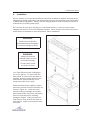
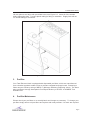
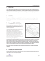
Installation and Operation Manual
Total Exhaust Hood
45 Iber Road, Ottawa Ontario, K2S 1E7
Tel: (613) 836-6065, 1-888-636-8609 / Fax: (613) 836-9724, www.designfiltration.com
Total Exhaust Hood
Table of Contents
1.
Shipping and Un-Crating . . . . . . . . . . . . . . . . . . . . . . . . . . . . . . . . . . . . . Pg. 2
2.
Installation . . . . . . . . . . . . . . . . . . . . . . . . . . . . . . . . . . . . . . . . . . . . . . . . Pg. 3
3.
Pre-filter . . . . . . . . . . . . . . . . . . . . . . . . . . . . . . . . . . . . . . . . . . . . . . . . . . Pg. 4
4.
Pre-filter Maintenance . . . . . . . . . . . . . . . . . . . . . . . . . . . . . . . . . . . . . . . Pg. 4
5.
HEPA Filter . . . . . . . . . . . . . . . . . . . . . . . . . . . . . . . . . . . . . . . . . . . . . . . . Pg. 5
6.
ULPA Filter . . . . . . . . . . . . . . . . . . . . . . . . . . . . . . . . . . . . . . . . . . . . . . . . Pg. 5
7.
Changing HEPA / ULPA Filters . . . . . . . . . . . . . . . . . . . . . . . . . . . . . . . . Pg. 5
8.
Changing the Fluorescent Light . . . . . . . . . . . . . . . . . . . . . . . . . . . . . . . . Pg. 5
9.
Speed Control . . . . . . . . . . . . . . . . . . . . . . . . . . . . . . . . . . . . . . . . . . . . . . Pg. 6
10. Exhaust System Safety Pressure Switch . . . . . . . . . . . . . . . . . . . . . . . . . Pg. 6
11. Model Number . . . . . . . . . . . . . . . . . . . . . . . . . . . . . . . . . . . . . . . . . . . . . Pg. 6
12. Motor / Electrical . . . . . . . . . . . . . . . . . . . . . . . . . . . . . . . . . . . . . . . . . . . . Pg. 6
13. Changing Sash Window Cables . . . . . . . . . . . . . . . . . . . . . . . . . . . . . . . . Pg. 6
14. Airflow Chart Specifications . . . . . . . . . . . . . . . . . . . . . . . . . . . . . . . . . . . Pg. 7
15. Airflow Direction . . . . . . . . . . . . . . . . . . . . . . . . . . . . . . . . . . . . . . . . . . . . Pg. 7
16. Dimensions . . . . . . . . . . . . . . . . . . . . . . . . . . . . . . . . . . . . . . . . . . . . . . . . Pg. 8
17. Replacement Parts . . . . . . . . . . . . . . . . . . . . . . . . . . . . . . . . . . . . . . . . . . Pg. 8
18. Warranty . . . . . . . . . . . . . . . . . . . . . . . . . . . . . . . . . . . . . . . . . . . . . . . . . . Pg. 9
Total Exhaust Hood
TOTAL EXHAUST HOOD
Thank you for purchasing our Total Exhaust Hood. W ith proper care and maintenance your
hood will provide you with many years of trouble free performance.
Please read instructions carefully before installing and
operating your Total Exhaust Hood.
W ARNING: To reduce risk of fire, electric shock, or injury to persons please
review the following precautions.
•
Do not expose your hood to rain or moisture.
•
Always disconnect the Total Exhaust Hood from power supply when servicing,
moving parts may cause serious injury.
•
Always disconnect while grasping the plug, not the cord.
•
Do not block airflow to top of unit (allow at least 5” above unit).
•
Do not expose your hood to gaseous or explosive vapors. Motors normally spark
and may ignite fumes.
•
Do not modify the plug of your hood if it will not fit in your duplex outlet. Have a
proper outlet installed by a qualified electrician.
1.
•
Use only specified replacement parts recommended by Design Filtration.
•
Use this equipment only in the manner intended by Design Filtration.
Shipping and Un-Crating
Your Total Exhaust Hood normally is shipped in two sections; smaller units may come fully
assembled. Units should be stored in heated conditions of between 4 /C (40 /F) and 32 /C
(90 /f) to avoid undue structural fatigue and damage.
Each unit is factory tested for airflows and filter leaks prior to shipping. On occasion damage
can occur during the transportation of your new Total Exhaust Hood. Carefully remove the
crating from your hood and inspect for damage that may have been caused and report it
immediately to your transportation company.
All shipments are F.O.B. Design Filtration Inc. You must file a claim directly with the freight
carrier. Design Filtration Inc. and its dealers are not responsible for shipping damages.
Pg.2
Total Exhaust Hood
2.
Installation
Once in location it is recommended that your hood be re-tested for airflows and leaks by an
independent testing organization with technicians trained in the evaluation and maintenance
of HEPA filtered equipment. Always use safe lifting guidelines when installing your hood on
a base frame or existing work bench.
Do not use a lift truck when moving your Total Exhaust Hood. Leave your hood on the
shipping skid until it is in its final installation location. Never lift from the centre of the hood.
Allow hood to acclimatize to room temperature, before installation.
WARNING:
Allow 24 Hrs for Hood to
Acclimatize Before Installation,
to Prevent Damage to Hood.
WARNING:
Always Lift from the
Outside Edges of Hood
to Prevent Damage.
Do Not Use Fork Lift
on Center of Hood.
Your Total Exhaust Hood is shipped to
you in four pieces. To start, locate the
base frame as close to the final area as
possible, allowing enough space for the
head section and personnel to move
freely around the front or back.
Place the wood blocks supplied, angled
across the corners of the work surface, as
shown in Figure 2.1. Raise the head
section keeping as straight as possible.
Move head section over base, and gently
lower on the wood pieces, avoiding
damage to fingers. Lifting one end at a
time remove wood spacers and lower to
base section, aligning connection screws
as shown.
Figure 2.1
Pg.3
Total Exhaust Hood
Lift rear plenum and align with pre-drilled holes, see Figure 2.2. Insert all of the screws
before tightening them. Connect plastic tubing to fitting on transition. Supply fans will not
run unless tubing is connected.
Figure 2.2
3.
Pre-filter
Your Total Exhaust Hood is equipped with disposable pre-filters, which are manufactured
from a bonded synthetic media set into a moisture resistant beverage board. Pleated prefilters carry an efficiency rating of MERV 7 (Minimum Efficiency Reporting Value). The filters
also provide an Average Atmospheric Dust Spot Efficiency of 25-30% to ASHRAE Test
Standard 52.1
4.
Pre-filter Maintenance
Please check your pre-filters on a monthly basis and change as necessary. To change your
pre-filter simply remove old pre-filters and replace with new pre-filters. No tools are required
Pg.4
Total Exhaust Hood
5.
HEPA Filter
Your Total Exhaust Hood features a 5.88” deep wood frame filter with a separatorless type
media to provide excellent even airflows. The wet laid glass media is set into the frame with
a urethane seal. Efficiency is 99.99% at 0.3-micron particle size and larger. HEPA filters
cannot be cleaned and must be replaced when necessary, consult factory for replacement
filters.
6.
ULPA Filter
The optional ULPA filter is rated 99.9995% at 0.12-micron particle size and larger. Other
features as per HEPA filter. ULPA filters cannot be cleaned and must be replaced when
necessary.
7.
Changing HEPA / ULPA Filters
Before beginning to change your HEPA Filter,
disconnect your hood from power source.
Carefully remove front access panel to reveal
interior compartment.
Loosen threaded rods at front and rear of fan
filter module. Unscrew and remove
polypropylene front locating bar. Remove
¼–20 nuts from rear clamping mechanism.
Unplug fan power cords from electrical outlet.
Carefully slide fan filter module from housing
(this may require two people.) Remove
aluminum foil tape and separate the filter from
motor housing. See Figure 7.1.
Figure 7.1
Carefully remove the new HEPA filter from crate. Using aluminum foil tape (do not use duct
tape) complete at least 3 layers of tape joining the fan housing to the filter. Apply a thin
layer of vacuum grease to gasket before re-installing the filter. Carefully lift and place filter
back into the hood making sure the HEPA filter is not damaged. W hen tightening threaded
rods, do not over tighten as these are only used to hold filter housing in place.
Once entire unit is re-assembled it must be tested and certified by a qualified certification
company.
8.
Changing the Fluorescent Light
Carefully remove the screws on the lense cover, remove the bulb and install new bulb with
same type and color as original supplied.
Pg.5
Total Exhaust Hood
9.
Speed Control
The speed control should only be adjusted by a qualified service technician. Adjusting the
airflow will affect the operation of your hood due to the critical balance required. Remove
front snap cap located on the front panel to access the speed control. Use a flat headed
screwdriver to adjust speed, turning clockwise to increase speed. After adjustment of the
speed control, airflows should be checked to ensure it is within the specified range as
outlined in chart. Refer to IES standard IES-RP-CC-002.2.
10. Exhaust System Safety Pressure Switch
This switch is located inside the head section and is connected to the exhaust collar via
tubing. In the case of total or partial exhaust failure, this switch will turn off the supply fans,
ensuring no air will be blown out of the containment work zone. Supply fans will not run
unless tubing is connected.
11. Model Number
The model number is located on the front panel in the lower right hand corner. The serial
number and electrical information is also included on this label. Refer to these numbers
when contacting the manufacturer.
12. Motor / Electrical
The Total Exhaust Hood uses 115-volt, 90-watt energy efficient motorized impellers to
provide excellent airflow distribution, quieter noise levels and low heat loads. Standard on
your Total Exhaust Hood is a FT2 type CSA approved 3-prong electrical cord. Always
unplug your hood when servicing.
13. Changing Sash Window Cables
Should the event of a sash cable replacement be required lift the window as high as
possible and support with two wooden studs cut to length. Remove the interior side panels
(LHS and RHS), remove the old cable and support the weight with a temporary 2” high
stand (this will compensate for stretching of the cable later). Attach new c’’ dia.
polypropylene rope, with a rating of at least 45lbs, to window end first. Thread through
pulleys and secure around weight eyelet with cable as tight as possible.
Always change both ropes at the same time. Consult factory for full rope specifications.
Pg.6
Total Exhaust Hood
14. Airflow Chart Specifications
Model #
Supply (CFM)
(60-70 FPM)
Exhaust (CFM)
(100-110 FPM)
Base Vent
(CFM)
Hand Intake (CFM)
TXH-4
535
846
271
40
TXH-5
673
1054
341
40
TXH-6
811
1262
411
40
TXH-8
1088
1679
551
40
Calculations are based on an average of: 105 FPM for Hand Intake, and 65 FPM for down flow
velocity m easured at 6” below diffuser screen.
15. Airflow Direction
W hen the Total Exhaust Hood is
operating, the fans draw lab air into the
hood from the top through the pre-filter
and the HEPA/ULPA filter, and then
pushes the cleaned air down to the work
surface. Figure15.1 shows the direction
of airflow in the hood.
Figure 15.1
Pg.7
Total Exhaust Hood
16. Dimensions
Model
Exterior Dimensions*
(W x D x H)
Collar Size / Qty.
Electrical**
TXH-4
52” x 37¼” x 93”
10” / 1
115V, 1.88A, 60Hz
TXH-5
64” x 37¼” x 93”
10” / 1
115V, 2.55A, 60Hz
TXH-6
76” x 37¼” x 93”
10” / 1
115V, 2.55A, 60Hz
TXH-8
100” x 37¼” x 93”
10” / 2
115V, 4.84A, 60Hz
* Height does not include base fram e. ** Includes m otors and lights only. Duplex Outlets run on a
separate circuit.
For size and weight of shipping crates, contact manufacturer.
17. Replacement Parts
Part
Order Number
Pre-filters nominal 12’’ x 24 x 2’’
12-12242-113
EBM 220 motor
17MOTR2E220AA4423
Motor capacitor
17CAP10MF
Speed Control
17SW SC1150L
TXH-4 HEPA Filter Bead pleat
10-24486-14
TXH-5 HEPA Filter Bead pleat
10-24606-14
TXH-6 HEPA Filter Bead pleat
10-24726-14
TXH-8 HEPA Filter Bead pleat, (quantity 2)
10-24486-14
TXH-4 ULPA Filter Bead pleat
10-24486-16
TXH-5 ULPA Filter Bead pleat
10-24606-16
TXH-6 ULPA Filter Bead pleat
10-24726-16
TXH-8 ULPA Filter Bead pleat, (quantity 2)
10-24486-16
For polypropylene rope replacement consult factory
For all plumbing components consult factory for full listings
Pg.8
Total Exhaust Hood
18. Warranty
Design Filtration Inc. warrants the equipment to be free of defects in materials and
workmanship from the date of invoice. The Total Exhaust Hood shall be warranted against
defects for a period of three years. Any units or parts found to be defective during this
period will be replaced or repaired at our discretion. The buyer agrees to assume all
transportation charges prepaid for return of unit to factory for repair. Design Filtration Inc
will not accept charges for removal or re-installation. Design Filtration will not accept any
returned items without prior written consent. Design Filtration Inc is not responsible for
repair or replacement by misuse or abuse by incorrect operating procedures of its
equipment. Pre-filters carry no warranty against loading. Any modifications or changes
made to equipment by customer without written consent of Design Filtration will void the
warranty.
Model number and serial number located on the head section of your Total Exhaust Hood
must be provided to verify invoice date. Failure to provide will void warranty.
F OR F URTHER INFORMATION , P LEASE C ONTACT U S D IRECTLY .
Design Filtration Inc., 45 Iber Road, Ottawa, ON. K2S 1E7
T: 1-888-636-8609 (Canada & USA), T: 1-613-836-6065, F: 1-613-836-9724
[email protected]
Pg.9