1
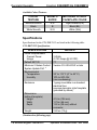
Crestron C2N-DBF12 & C2N-DBN12 Decorator Keypads Operations & Installation Guide This document was prepared and written by the Technical Documentation department at: Regulatory Compliance As of the date of manufacture, the C2N-DBF12 and C2N-DBN12 have been tested and found to comply with specifications for CE marking and standards per EMC and Radiocommunications Compliance Labelling. Federal Communications Commission (FCC) Compliance Statement This device complies with part 15 of the FCC Rules. Operation is subject to the following conditions: (1) This device may not cause harmful interference and (2) this device must accept any interference received, including interference that may cause undesired operation. CAUTION: Changes or modifications not expressly approved by the manufacturer responsible for compliance could void the user’s authority to operate the equipment. NOTE: This equipment has been tested and found to comply with the limits for a Class B digital device, pursuant to part 15 of the FCC Rules. These limits are designed to provide reasonable protection against harmful interference in a residential installation. This equipment generates, uses and can radiate radio frequency energy and, if not installed and used in accordance with the instructions, may cause harmful interference to radio communications. However, there is no guarantee that interference will not occur in a particular installation. If this equipment does cause harmful interference to radio or television reception, which can be determined by turning the equipment off and on, the user is encouraged to try to correct the interference by one or more of the following measures: • Reorient or relocate the receiving antenna • Increase the separation between the equipment and receiver • Connect the equipment into an outlet on a circuit different from that to which the receiver is connected • Consult the dealer or an experienced radio/TV technician for help Industry Canada (IC) Compliance Statement CAN ICES-3(B)/NMB-3(B) The specific patents that cover Crestron products are listed at patents.crestron.com. Crestron, the Crestron logo, Adagio, Cresnet, Crestron Toolbox, SIMPL+, and SystemBuilder are either trademarks or registered trademarks of Crestron Electronics, Inc. in the United States and/or other countries. Lutron is either a trademark or registered trademark of Lutron Electronics, Inc. in the United States and/or other countries. Windows is either a trademark or registered trademark of Microsoft Corporation in the United States and/or other countries. Other trademarks, registered trademarks, and trade names may be used in this document to refer to either the entities claiming the marks and names or their products. Crestron disclaims any proprietary interest in the marks and names of others. ©2012 Crestron Electronics, Inc. Crestron C2N-DBF12 & C2N-DBN12 Decorator Keypads Contents Decorator Keypads: C2N-DBF12 & C2N-DBN12 1 Introduction ............................................................................................................................... 1 Features and Functions ................................................................................................ 1 Specifications .............................................................................................................. 2 Physical Description .................................................................................................... 4 Setup .......................................................................................................................................... 8 Network Wiring ........................................................................................................... 8 Identity Code ............................................................................................................... 8 Assembly and Installation ........................................................................................... 8 Hardware Hookup ..................................................................................................... 11 Button Replacement .................................................................................................. 12 Programming Software ............................................................................................................ 13 Software Requirements for the PC ............................................................................ 13 Programming with Crestron SystemBuilder .............................................................. 14 Programming with SIMPL Windows ........................................................................ 14 Uploading and Upgrading ........................................................................................................ 17 Establishing Communication ..................................................................................... 17 Programs and Firmware ............................................................................................ 18 Program Checks ........................................................................................................ 18 Operation ................................................................................................................................. 19 Problem Solving ...................................................................................................................... 20 Troubleshooting......................................................................................................... 20 Check Network Wiring.............................................................................................. 22 Reference Documents ................................................................................................ 23 Further Inquiries ........................................................................................................ 23 Future Updates .......................................................................................................... 24 Return and Warranty Policies .................................................................................................. 25 Merchandise Returns / Repair Service ...................................................................... 25 Crestron Limited Warranty........................................................................................ 25 Operations & Installation Guide – DOC. 6200C Contents • i Crestron C2N-DBF12 & C2N-DBN12 Decorator Keypads Decorator Keypads: C2N-DBF12 & C2N-DBN12 Introduction Decorator Keypads provide a cost-effective room control solution for Adagio® and other Crestron® AV distribution systems. The C2N-DBF12 includes a set of 30 assorted button caps labeled for AV source selection and control functions. The C2N-DBN12 complements the C2N-DBF12, adding a set of numeric buttons for direct entry of channels, titles and tracks. For simplicity within this guide, the term “C2N-DBF/N12” is used except where noted. Features and Functions • • • • • • • • Simple design with 12 buttons and feedback LEDs New color-matched “smooth” finishes Includes pre-labeled button caps for numeric entry1 Includes 30 pre-labeled button caps — provides six source select and six AV control buttons2 Optional numeric entry keypad2 Fits standard electrical gang boxes and decorator style faceplates Available in smooth almond, black and white finishes Easy Cresnet® wiring NOTE: Keypads can also be mounted in multigang electrical boxes. 1. C2N-DBN12 only. 2. C2N-DBF12 only. Operations & Installation Guide – DOC. 6200C Decorator Keypads: C2N-DBF/N12 • 1 Decorator Keypads Crestron C2N-DBF12 & C2N-DBN12 Available Colors/Textures COLOR/ TEXTURE MODEL # SUFFIX MATCHING LUTRON® FACEPLATE COLOR Almond Smooth Black White Smooth A-S B W-S Light Almond (LA) Black (BL) White (WH) Specifications Specifications for the C2N-DBF/N12 are listed in the following table. C2N-DBF/N12 Specifications SPECIFICATION DETAILS Power Requirements Cresnet Power Usage Default NET ID Minimum 2-Series Control System Update File1, 2 Environmental Temperature Humidity 3 Watts (0.125 Amps @ 24 VDC) 71 Version C2-2.004.CUZ or later 32° to 113° F (0° to 45° C) 10% to 90% RH (non-condensing) 1-gang mountable in a standard electrical box; requires decorator style faceplate (provided by others) Enclosure Dimensions (without faceplate) Height Width Depth 4.16 in (106 mm) 1.79 in (46 mm) 1.53 in (39 mm) without connector 2.60 oz (75 g) Weight (Continued on following page) 2 • Decorator Keypads: C2N-DBF/N12 Operations & Installation Guide – DOC. 6200C Crestron C2N-DBF12 & C2N-DBN12 Decorator Keypads C2N-DBF/N12 Specifications (Continued) SPECIFICATION Available Models C2N-DBF/N12-A-S C2N-DBF/N12-W-S C2N-DBF/N12B Included Accessories DB12-BTN-A-S3 DB12-BTN-W-S3 DB12-BTNB3 Available Accessories CCR-L-1 CRESNET-HP-NP-TL CRESNET-NP[TL,BK,OR,YL] CRESNET-P[TL,BK,OR,YL] DB12-BTN-A-S DB12-BTN-W-S DB12-BTNB DETAILS 12-Button Decorator Numeric/Function Keypad Almond Smooth White Smooth Black Engravable Button Caps with Default Engraving, Almond, Smooth Engravable Button Caps with Default Engraving, White, Smooth Engravable Button Caps with Default Engraving, Black Crestron Color Ring Cresnet “High-Power” Control Cable, non-plenum, teal Cresnet Control Cable, non-plenum Cresnet Control Cable, plenum Engravable Button Cap, Almond, Smooth Engravable Button Cap, White, Smooth Engravable Button Cap, Black, Smooth 1. The latest software versions can be obtained from the Crestron Web site. Refer to the NOTE following these footnotes. 2. Crestron 2-Series Control Systems include the AV2 and PRO2. Consult the latest Crestron Product Catalog for a complete list of 2-Series Control Systems. 3. C2N-DBF12 comes with 30 button caps. C2N-DBN12 comes with 12 button caps. Operations & Installation Guide – DOC. 6200C Decorator Keypads: C2N-DBF/N12 • 3 Decorator Keypads Crestron C2N-DBF12 & C2N-DBN12 NOTE: Crestron software and any files on the Web site are for authorized Crestron dealers and Crestron Authorized Independent Programmers (CAIP) only. New users may be required to register to obtain access to certain areas of the site (including the FTP site). Physical Description This section provides information on the connections, controls and indicators available on the C2N-DBF/N12. C2N-DBN12 & C2N-DBF12 Physical Views C2N-DBN12 (Black Color) C2N-DBF12 (White Color) NOTE: Faceplates, as shown in the above illustration, are not supplied with the keypads. 4 • Decorator Keypads: C2N-DBF/N12 Operations & Installation Guide – DOC. 6200C Crestron C2N-DBF12 & C2N-DBN12 Decorator Keypads C2N-DBF12 & C2N-DBN12 Overall Dimensions Side View with Buttons Installed 1.53 in (39 mm) 1.07 in (28 mm) Front View with Divider and Buttons Removed 1.79 in (46 mm) Back View 1.70 in (44 mm) 4.16 in (106 mm) 1 Rubber Membrane Operations & Installation Guide – DOC. 6200C 2.70 in (69 mm) 2 3 Decorator Keypads: C2N-DBF/N12 • 5 Crestron C2N-DBF12 & C2N-DBN12 Decorator Keypads Connectors, Controls & Indicators * # CONNECTORS*, CONTROLS & INDICATORS DESCRIPTION 1 Buttons 2 LED Indicators 3 NET* (12) Replaceable pre-labeled buttons, programmable (1 per button) Red LED, programmable and dimmable (1) 4-pin 3.5 mm detachable terminal block; Cresnet slave port, connects to Cresnet control network; 24: Power (24 VDC) Y: Data Z: Data G: Ground Interface connector for NET is provided with the unit. Button Arrangements C2N-DBN12 C2N-DBF12 Standard Button Set C2N-DBF12 Extra Button Set CLEAR ENTER CD FM ADAGIO AM DSS 1 2 JUKE SAT DSS 2 DVD FM 2 3 4 IPOD AUX IPOD 2 JUKE 2 MUSIC 5 6 ON-OFF MUTE SAT 2 SERVER SIRIUS 7 8 VOL SIRIUS TUNER TV 9 0 VOL VCR XM XM 6 • Decorator Keypads: C2N-DBF/N12 Operations & Installation Guide – DOC. 6200C Crestron C2N-DBF12 & C2N-DBN12 Decorator Keypads The keypads come fully assembled and each has 12 buttons with LED windows (refer to illustration on page 4). The C2N-DBF12 has six source selector buttons, an ON-OFF button, a MUTE button, and device transport control and volume control buttons. A kit with additional source buttons for the C2N-DBF12 is also provided (refer to illustration on page 6). The C2N-DBN12 has a CLEAR button, an ENTER button, and numeric digit buttons 0 through 9. Operations & Installation Guide – DOC. 6200C Decorator Keypads: C2N-DBF/N12 • 7 Decorator Keypads Crestron C2N-DBF12 & C2N-DBN12 Setup Network Wiring When wiring the network, consider the following: • Use Crestron Certified Wire. • Use Crestron power supplies for Crestron equipment. • Provide sufficient power to the system. CAUTION: Insufficient power can lead to unpredictable results or damage to the equipment. Please use the Crestron Power Calculator to help calculate how much power is needed for the system (www.crestron.com/calculators). For networks with 20 or more devices, use a Cresnet® Hub/Repeater (CNXHUB) to maintain signal quality. For more details, refer to “Check Network Wiring” on page 22. Identity Code The Net ID of the C2NDBF/N12 has been factory set to 71. The Net IDs of multiple C2NDBF/N12 devices in the same system must be unique. Net IDs are changed from a personal computer (PC) via the Crestron Toolbox™ (refer to “Establishing Communication” on page 17). When setting the Net ID, consider the following: • The Net ID of each unit must match an ID code specified in the SIMPL Windows program. • Each network device must have a unique Net ID. For more details, refer to the Crestron Toolbox help file. Assembly and Installation The following tools/hardware are required for installation. • Cresnet network cable (sold separately) • Phillips screwdriver (not supplied) • Two 1 inch pan head Phillips screws (supplied) 8 • Decorator Keypads: C2N-DBF/N12 Operations & Installation Guide – DOC. 6200C Crestron C2N-DBF12 & C2N-DBN12 Decorator Keypads Assemble the keypad as described in the following steps. Refer to the accompanying illustration. 1. Place the removable buttons on the keypad assembly, making sure they are properly oriented with the LED windows facing up. 2. Carefully position the divider over the button caps on the keypad assembly. 3. Install and tighten the four supplied 2-28 x 3/16” screws. 4. Press each button and release to ensure that the button caps move freely. Assembly View Keypad Removable buttons (Refer to CAUTION on page 12.) Divider LED window 2-28 x 3/16 in. pan head screws After the Cresnet network wiring has been installed and verified, use the following procedure to install the keypad in a standard, 1-gang electrical box. Refer to the accompanying illustration. 1. Turn Cresnet system power OFF. 2. Connect the Cresnet cable to the keypad’s NET port, using the supplied mating connector. Connect the other end to the control system. Operations & Installation Guide – DOC. 6200C Decorator Keypads: C2N-DBF/N12 • 9 Crestron C2N-DBF12 & C2N-DBN12 Decorator Keypads 3. Make sure the keypad is oriented properly (note the arrow labeled “TOP” on the keypad assembly), place it in the electrical box, and attach it using the included 6-32 x 1" pan head screws. CAUTION: Excess wire pinched between the keypad and electrical box could cause a short circuit. Make sure all excess wire is completely inside the electrical box and not between the box and the keypad. 4. Attach faceplate (not shown). Installation View 1-gang electrical box shown; (2.5 in. depth recommended) Can also mount in multigang boxes (electrical boxes not supplied) 6-32 x1in. pan head screw 5. Turn on Cresnet system power. 10 • Decorator Keypads: C2N-DBF/N12 Operations & Installation Guide – DOC. 6200C Crestron C2N-DBF12 & C2N-DBN12 Decorator Keypads Hardware Hookup Make the necessary connections as called out in the illustration below. Refer to “Network Wiring” on page 8 before attaching the 4-position terminal block connector. Apply power after all connections have been made. When making connections to the C2N-DBF/N12, use Crestron power supplies for Crestron equipment. Hardware Connections for the C2N-DBF/N12 (Back view) NET - 24 Y Z G: Connect to the Cresnet Control Network Operations & Installation Guide – DOC. 6200C Decorator Keypads: C2N-DBF/N12 • 11 Decorator Keypads Crestron C2N-DBF12 & C2N-DBN12 Button Replacement Replacing/changing the removable buttons in a keypad is a simple process. 1. If the keypad is installed in an electrical box, remove the faceplate and two 1 inch securing screws and carefully pull the keypad from the electrical box. 2. Disconnect the Cresnet cable. 3. Remove the four screws that attach the divider, and remove the divider. Refer to the illustration on page 9 for details. CAUTION: The removable buttons fit snugly on the rubber membrane and must be removed carefully to avoid pulling the membrane from the unit. Once the membrane is detached, it may not be possible to reattach it. 4. While holding adjacent buttons in place, carefully pull the button(s) to be replaced from the rubber membrane. 5. Carefully press the replacement button(s) in place and make sure LED window(s) orientation is correct. Refer to the illustration on page 9 for correct orientation. 6. Attach the divider using the four screws removed in step 3. 7. Reinstall the keypad in the electrical box. For details refer to “Assembly and Installation” which starts on page 8. 12 • Decorator Keypads: C2N-DBF/N12 Operations & Installation Guide – DOC. 6200C Crestron C2N-DBF12 & C2N-DBN12 Decorator Keypads Programming Software Have a question or comment about Crestron software? Answers to frequently asked questions (FAQs) can be viewed in the Online Help section of the Crestron Web site. To post a question or to view questions submitted to Crestron’s True Blue Support, log in at www.crestron.com/onlinehelp. First-time users must establish a user account to fully benefit from all available features. Software Requirements for the PC NOTE: The latest software can be downloaded from the Crestron Web site (www.crestron.com/software). Crestron provides an assortment of Windows-based software tools to develop a customized system. Use SystemBuilder™ or SIMPL Windows to create a program to control the C2N-DBF/N12. Software TASK REQUIRED SOFTWARE VERSION Program control system to operate C2N-DBF/N12. SIMPL Windows version 2.04.11 or later with SIMPL+ Cross Compiler version 1.1 or later and Library update 227 or later; Also requires Crestron Database version 15.9.8 or later. Crestron Toolbox 1.01.06 or later. Upload program and firmware. Program with simple wizards for systems using a C2N-DBF/N12 (optional but recommended). Operations & Installation Guide – DOC. 6200C Crestron SystemBuilder version 2.0 or later with SystemBuilder Templates version 2.0 or later. Refer to software release notes or Crestron Web site for other required Crestron software packages. Decorator Keypads: C2N-DBF/N12 • 13 Decorator Keypads Crestron C2N-DBF12 & C2N-DBN12 Programming with Crestron SystemBuilder SystemBuilder is a comprehensive programming environment. Appropriate for most systems, it can quickly and easily generate a complete working program including both control processor logic and touch screen graphics. Programming with SIMPL Windows NOTE: While SIMPL Windows can be used to program the C2N-DBF/N12, it is recommended to use SystemBuilder for configuring a system. SIMPL Windows is Crestron’s premier software for programming Crestron control systems. It is organized into two separate, but equally important “Managers”: Configuration and Program. Configuration Configuration Manager is the view where programmers “build” a Manager Crestron control system by selecting hardware from the Device Library. 1. To incorporate the C2N-DBF/N12 into the system, drag the C2N-DBF/N12 from the Wired Keypad folder of the Device Library and drop it in the System Views. Locating the C2N-DBF12 & C2N-DBN12 in the Device Library The system tree of the control system displays the device in the appropriate slot with a default Net ID as shown in the illustration on the following page. 14 • Decorator Keypads: C2N-DBF/N12 Operations & Installation Guide – DOC. 6200C Crestron C2N-DBF12 & C2N-DBN12 Decorator Keypads C2Net-Device, Slot 1 (C2N-DBF12 shown) 2. If additional C2N-DBF12 or C2N-DBN12 devices are to be added, repeat step 1 for each device. Each C2N-DBF/N12 is assigned a different Net ID number as it is added. 3. If necessary, double click a device to open the “Device Settings” window and change the Net ID, as shown in the following illustration. “Device Settings: Crestron C2N-DBF12” Window (C2N-DBN12 not shown) Operations & Installation Guide – DOC. 6200C Decorator Keypads: C2N-DBF/N12 • 15 Decorator Keypads Crestron C2N-DBF12 & C2N-DBN12 NOTE: The ID code specified in the SIMPL Windows program must match the Net ID of each unit. Refer to “Identity Code” on page 8. Program Manager Program Manager is the view where programmers “program” a Crestron control system by assigning signals to symbols. The symbol can be viewed by double clicking on the icon or dragging it into Detail View. Each signal in the symbol is described in the SIMPL Windows help file (F1). 16 • Decorator Keypads: C2N-DBF/N12 Operations & Installation Guide – DOC. 6200C Crestron C2N-DBF12 & C2N-DBN12 Decorator Keypads Uploading and Upgrading Crestron recommends using the latest programming software and that each device contains the latest firmware to take advantage of the most recently released features. However, before attempting to upload or upgrade it is necessary to establish communication. Once communication has been established, files (for example, programs or firmware) can be transferred to the control system (or device). Program checks can be performed (such as changing the device ID or creating an IP table) to ensure proper functioning. Establishing Communication Use Crestron Toolbox for communicating with the C2N-DBF/N12; refer to the Crestron Toolbox help file for details. There is a single method of communication: indirect serial communication. Indirect Serial Communication Serial, LA N Control System Cresnet C2N-DBF/N12 or USB PC Running Crestron Toolbox C2N-DBF/N12 connects to control system via Cresnet: 1. Establish communication between the PC and the control system as described in the latest version of the 2-Series Control Systems Reference Guide (Doc. 6256), which is available from the Crestron Web site (www.crestron.com/manuals). 2. Use the Address Book in Crestron Toolbox to create an entry for the C2N-DBF/N12 using the expected communication protocol (indirect). Select the Cresnet ID of the C2N-DBF/N12 and the address book entry of the control system that is connected to the C2N-DBF/N12. Operations & Installation Guide – DOC. 6200C Decorator Keypads: C2N-DBF/N12 • 17 Decorator Keypads Crestron C2N-DBF12 & C2N-DBN12 3. Display the C2N-DBF/N12’s “System Info” window (click the icon); communications are confirmed when the device information is displayed. Programs and Firmware Program or firmware files may be distributed from programmers to installers or from Crestron to dealers. Firmware upgrades are available from the Crestron Web site as new features are developed after product releases. One has the option to upload programs via the programming software or to upload and upgrade via the Crestron Toolbox. For details on uploading and upgrading, refer to the SIMPL Windows help file or the Crestron Toolbox help file. SIMPL Windows If a SIMPL Windows program is provided, it can be uploaded to the control system using SIMPL Windows or Crestron Toolbox. Firmware Check the Crestron Web site to find the latest firmware. (New users may be required to register to obtain access to certain areas of the site, including the FTP site.) NOTE: During firmware loads, all LEDs blink at a slow rate. Upgrade C2N-DBF/N12 firmware via Crestron Toolbox. 1. Establish communication with the C2N-DBF/N12 and display the “System Info” window. 2. Select Functions | Firmware… to upgrade the C2N-DBF/N12 firmware. Program Checks For Cresnet connections, using Crestron Toolbox, display the network device tree (Tools | Network Device Tree View) to show all network devices connected to the control system. Right-click on the C2N-DBF/N12 to display actions that can be performed on the C2N-DBF/N12. 18 • Decorator Keypads: C2N-DBF/N12 Operations & Installation Guide – DOC. 6200C Crestron C2N-DBF12 & C2N-DBN12 Decorator Keypads Operation The C2N-DBF12 serves as a source keypad, providing a cost-effective room control solution for Adagio and other Crestron AV distribution systems. It includes a set of 30 assorted button caps labeled for AV source selection and control functions. The C2N-DBN12 can be used to expand the capabilities of the source keypad and is ideal for audio device functions such as selecting a particular CD track number or a certain CD from a CD changer. All buttons on the keypad are functionally identical and have light emitting diodes (LEDs) that serve as user feedback indicators. Each LED’s illumination (on/off) is independently addressable and is programmable using SIMPL Windows. In the program, the intensity level for all of the button LEDs can be set from 0 to 100%. Operations & Installation Guide – DOC. 6200C Decorator Keypads: C2N-DBF/N12 • 19 Crestron C2N-DBF12 & C2N-DBN12 Decorator Keypads Problem Solving Troubleshooting The table below provides corrective action for possible trouble situations. If further assistance is required, please contact a Crestron customer service representative. C2N-DBF/N12 Troubleshooting TROUBLE POSSIBLE CAUSE(S) CORRECTIVE ACTION Keypad does not function. Keypad is not communicating with the network. Use Crestron Toolbox to poll the network. Verify network connection to the device. Use Crestron power source. Verify connections. Keypad is not receiving power from a Crestron power source. Keypad is not receiving sufficient power. Keypad Net ID is not correct. Keypad Net ID is not set to match the Net ID set in the SIMPL Windows program. Use the Crestron Power Calculator to help calculate how much power is needed for the system. In Toolbox, poll the network (F4) to verify Net ID. Verify Net ID setting in SIMPL Windows program. (Continued on following page) 20 • Decorator Keypads: C2N-DBF/N12 Operations & Installation Guide – DOC. 6200C Crestron C2N-DBF12 & C2N-DBN12 Decorator Keypads C2N-DBF/N12 Troubleshooting (Continued) TROUBLE POSSIBLE CAUSE(S) CORRECTIVE ACTION Keypad does not function (Continued). Keypad Net ID is the same as another device’s Net ID. Button LED does not illuminate. Feedback signal names incorrect in SIMPL Windows program. LED intensity set to 0 (zero). Firmware is loading. Assign a different Net ID in SIMPL Windows and reset unit using Toolbox. Verify SIMPL Windows program for feedback signal names. Set intensity to desired level. Wait until firmware load is complete. Reload firmware. All LEDs are blinking at a slow rate. All LEDs are blinking at a fast rate. Pressing button yields wrong result. The keypad has reverted to its bootloader firmware. The keypad is in TSID mode. Keypad is mounted upside down. Keypad programmed incorrectly. Operations & Installation Guide – DOC. 6200C Press any button to complete the TSID action. Check keypad orientation. Check programming in SIMPL Windows. Decorator Keypads: C2N-DBF/N12 • 21 Crestron C2N-DBF12 & C2N-DBN12 Decorator Keypads Check Network Wiring Use the Right Wire To ensure optimum performance over the full range of the installation topology, use Crestron Certified Wire only. Failure to do so may incur additional charges if support is required to identify performance deficiencies because of using improper wire. Calculate Power CAUTION: Use only Crestron power supplies for Crestron equipment. Failure to do so could cause equipment damage or void the Crestron warranty. CAUTION: Provide sufficient power to the system. Insufficient power can lead to unpredictable results or damage to the equipment. Use the Crestron Power Calculator to help calculate how much power is needed for the system (www.crestron.com/calculators). When calculating the length of wire for a particular Cresnet run, the wire gauge and the Cresnet power usage of each network unit to be connected must be taken into consideration. Use Crestron Certified Wire only. If Cresnet units are to be daisy chained on the run, the Cresnet power usage of each network unit to be daisy chained must be added together to determine the Cresnet power usage of the entire chain. If the unit is run from a Crestron system power supply network port, the Cresnet power usage of that unit is the Cresnet power usage of the entire run. The wire gauge and the Cresnet power usage of the run should be used in the following equation to calculate the cable length value on the equation’s left side. Cable Length Equation 40,000 L< RxP Where: L = Length of run (or chain) in feet R = 6 Ohms (Crestron Certified Wire: 18 AWG (0.75 mm 2 )) or 1.6 Ohms (Cresnet HP: 12 AWG (4 mm 2 )) P = Cresnet power usage of entire run (or chain) Make sure the cable length value is less than the value calculated on the right side of the equation. For example, a Cresnet run using 18 AWG Crestron Certified Wire and drawing 20 watts should not have a length of run more than 333 feet (101 meters). If Cresnet HP is used for the same run, its length could extend to 1250 feet (381 meters). 22 • Decorator Keypads: C2N-DBF/N12 Operations & Installation Guide – DOC. 6200C Crestron C2N-DBF12 & C2N-DBN12 Decorator Keypads NOTE: All Crestron certified Cresnet wiring must consist of two twisted pairs. One twisted pair is the +24V conductor and the GND conductor and the other twisted pair is the Y conductor and the Z conductor. Strip and Tin Wire When daisy chaining Cresnet units, strip the ends of the wires carefully to avoid nicking the conductors. Twist together the ends of the wires that share a pin on the network connector and tin the twisted connection. Apply solder only to the ends of the twisted wires. Avoid tinning too far up the wires or the end becomes brittle. Insert the tinned connection into the Cresnet connector and tighten the retaining screw. Repeat the procedure for the other three conductors. Add Hubs Use of a Cresnet Hub/Repeater (CNXHUB) is advised whenever the number of Cresnet devices on a network exceeds 20 or when the combined total length of Cresnet cable exceeds 3000 feet (914 meters). Reference Documents The latest version of all documents mentioned within the guide can be obtained from the Crestron Web site (www.crestron.com/manuals). List of Related Reference Documents DOCUMENT TITLE 2-Series Control Systems Reference Guide Further Inquiries To locate specific information or to resolve questions after reviewing this guide, contact Crestron's True Blue Support at 1-888-CRESTRON [1-888-273-7876] or refer to the listing of Crestron worldwide offices on the Crestron Web site (www.crestron.com/offices) for assistance within a particular geographic region. To post a question about Crestron products, log onto the Online Help section of the Crestron Web site (www.crestron.com/onlinehelp). Firsttime users must establish a user account to fully benefit from all available features. Operations & Installation Guide – DOC. 6200C Decorator Keypads: C2N-DBF/N12 • 23 Decorator Keypads Crestron C2N-DBF12 & C2N-DBN12 Future Updates As Crestron improves functions, adds new features, and extends the capabilities of the C2N-DBF/N12, additional information may be made available as manual updates. These updates are solely electronic and serve as intermediary supplements prior to the release of a complete technical documentation revision. Check the Crestron Web site periodically for manual update availability and its relevance. Updates are identified as an “Addendum” in the Download column. 24 • Decorator Keypads: C2N-DBF/N12 Operations & Installation Guide – DOC. 6200C Crestron C2N-DBF12 & C2N-DBN12 Decorator Keypads Return and Warranty Policies Merchandise Returns / Repair Service 1. No merchandise may be returned for credit, exchange or service without prior authorization from Crestron. To obtain warranty service for Crestron products, contact an authorized Crestron dealer. Only authorized Crestron dealers may contact the factory and request an RMA (Return Merchandise Authorization) number. Enclose a note specifying the nature of the problem, name and phone number of contact person, RMA number and return address. 2. Products may be returned for credit, exchange or service with a Crestron Return Merchandise Authorization (RMA) number. Authorized returns must be shipped freight prepaid to Crestron, 6 Volvo Drive, Rockleigh, N.J. or its authorized subsidiaries with RMA number clearly marked on the outside of all cartons. Shipments arriving freight collect or without an RMA number shall be subject to refusal. Crestron reserves the right in its sole and absolute discretion to charge a 15% restocking fee plus shipping costs on any products returned with an RMA. 3. Return freight charges following repair of items under warranty shall be paid by Crestron, shipping by standard ground carrier. In the event repairs are found to be non-warranty, return freight costs shall be paid by the purchaser. Crestron Limited Warranty Crestron Electronics, Inc. warrants its products to be free from manufacturing defects in materials and workmanship under normal use for a period of three (3) years from the date of purchase from Crestron, with the following exceptions: disk drives and any other moving or rotating mechanical parts, pan/tilt heads and power supplies are covered for a period of one (1) year; touchscreen display and overlay components are covered for 90 days; batteries and incandescent lamps are not covered. This warranty extends to products purchased directly from Crestron or an authorized Crestron dealer. Purchasers should inquire of the dealer regarding the nature and extent of the dealer's warranty, if any. Crestron shall not be liable to honor the terms of this warranty if the product has been used in any application other than that for which it was intended or if it has been subjected to misuse, accidental damage, modification or improper installation procedures. Furthermore, this warranty does not cover any product that has had the serial number altered, defaced or removed. This warranty shall be the sole and exclusive remedy to the original purchaser. In no event shall Crestron be liable for incidental or consequential damages of any kind (property or economic damages inclusive) arising from the sale or use of this equipment. Crestron is not liable for any claim made by a third party or made by the purchaser for a third party. Crestron shall, at its option, repair or replace any product found defective without charge for parts or labor. Repaired or replaced equipment and parts supplied under this warranty shall be covered only by the unexpired portion of the warranty. Except as expressly set forth in this warranty, Crestron makes no other warranties expressed or implied nor authorizes any other party to offer any warranty, including any implied warranties of merchantability or fitness for a particular purpose. Any implied warranties that may be imposed by law are limited to the terms of this limited warranty. This warranty statement supersedes all previous warranties. Operations & Installation Guide – DOC. 6200C Decorator Keypads: C2N-DBF/N12 • 25 Crestron C2N-DBF12 & C2N-DBN12 Decorator Keypads This page is intentionally left blank. 26 • Decorator Keypads: C2N-DBF/N12 Operations & Installation Guide – DOC. 6200C Crestron C2N-DBF12 & C2N-DBN12 Decorator Keypads This page is intentionally left blank. Operations & Installation Guide – DOC. 6200C Decorator Keypads: C2N-DBF/N12 • 27 Crestron Electronics, Inc. 15 Volvo Drive Rockleigh, NJ 07647 Tel: 888.CRESTRON Fax: 201.767.7576 www.crestron.com Operations & Installation Guide – DOC. 6200C (2009208) 11.12 Specifications subject to change without notice.